Article

Cross-Path Planning of UAV Cluster Low-Altitude Flight Based on Inertial Navigation Combined with GPS Localization

1
School of Microelectronics, Hubei University, Wuhan 430062, China
2
Wuhan University Student Engineering Training and Innovation Practice Center, Wuhan University, Wuhan 430079, China
3
GNSS Research Center, Wuhan University, Wuhan 430079, China
4
School of Automation Science and Electrical Engineering, University of Science and Technology Beijing, Beijing 100083, China
5
School of Science, STEM College, RMIT University, Melbourne 3000, Australia
*
Author to whom correspondence should be addressed.
Electronics 2025, 14(14), 2877; https://doi.org/10.3390/electronics14142877
Submission received: 22 April 2025 / Revised: 9 July 2025 / Accepted: 15 July 2025 / Published: 18 July 2025

Abstract

To address the challenges of complex low-altitude flight environments for UAVs, where numerous obstacles often lead to GPS signal obstruction and multipath effects, this study proposes an integrated inertial navigation and GPS positioning approach for coordinated cross-path planning in drone swarms. The methodology involves the following: (1) discretizing continuous 3D airspace into grid cells using occupancy grid mapping to construct an environmental model; (2) analyzing dynamic flight characteristics through attitude angle variations in a 3D Cartesian coordinate system; and (3) implementing collaborative state updates and global positioning through fused inertial–GPS navigation. By incorporating Cramér–Rao lower bound optimization, the system achieves effective cross-path planning for drone formations. Experimental results demonstrate a 98.35% mission success rate with inter-drone navigation time differences maintained below 0.5 s, confirming the method’s effectiveness in enabling synchronized swarm operations while maintaining safe distances during cooperative monitoring and low-altitude flight missions. This approach demonstrates significant advantages in coordinated cross-path planning for UAV clusters.

1. Introduction

Low-altitude airspace is an important component of the national airspace system and the main flight area for various general aircraft, with enormous economic and social value [1,2]. Low-altitude airspace usually refers to the space area from the ground to a certain altitude, which is usually regulated by various countries. Generally, 300 m to 3000 m is considered as the space for civil aviation activities [3,4,5]. With the rapid development of drone technology, drone clusters have been widely used in logistics distribution, agricultural crop protection, urban inspection, emergency rescue, and other fields [6,7]. Especially in the low-altitude domain below 120 m, drone activities are becoming increasingly frequent. Traditional isolated airspace management methods may encounter efficiency bottlenecks when drone density is too high, leading to increasingly scarce airspace resources [8,9,10]. Therefore, effective planning and management of drone swarm flight paths in low-altitude airspace has gradually become an important research direction in the aviation field.
The low-altitude cross-path planning of unmanned aerial vehicle swarms is a complex and challenging problem [11,12]. Currently, several mature methods are widely adopted. Model predictive control (MPC) effectively solves the problem of multi-UAV cooperative planning in dynamic environments through online rolling optimization and feedback correction, and is particularly suitable for real-time obstacle avoidance and trajectory optimization. The Bézier curve method achieves smooth trajectory planning through parametric path generation, improving flight efficiency while meeting motion constraints. It is highly suitable for scenarios that require continuous differentiable paths. For example, reference [13] proposed an improved A* autonomous parking path planning algorithm, which adopted the third-order Bézier curve to optimize the path smoothness. The MPC path tracking control method based on the first-order Holder was designed, achieving high-precision automatic parking path planning control. The MPC method predicts the state of the unmanned aerial vehicle (UAV) within a certain period of time in the future and adjusts the control input to enable the UAV to track the planned path as much as possible. However, the distance relationship between the unmanned aerial vehicle (UAV) and other UAVs during the path tracking process was not considered, and it was unable to adjust its own flight trajectory in real time according to the positions and flight states of other UAVs.
Due to the complexity of the unmanned aerial vehicle (UAV) path planning scenarios, using a single MPC and Bézier curve method makes it difficult to comprehensively cope with them. Researchers explored from different perspectives, highlighting the performance of various methods in the path planning of unmanned aerial vehicles. Deep reinforcement learning, heuristic algorithms, and machine learning control are the current mainstream technical directions, which can systematically reflect the commonalities and deficiencies of multi-UAV collaborative safety constraints. Among them, deep reinforcement learning, as shown in reference [14], proposes a deep deterministic policy gradient algorithm in combination with aircraft dynamics. However, it is mainly based on final reward learning and lacks real-time feedback on the distance from other unmanned aerial vehicles during flight. It does not set a reward or punishment mechanism for the minimum safe distance, which may lead to the neglect of distance. Heuristic algorithm improvements, such as the two-layer intelligent dynamic path planning proposed in reference [15], although effective in obstacle avoidance, focus on single-machine offline optimization and lack multi-machine coordination, making it difficult to ensure the minimum safety distance. Although the improved Grey Wolf algorithm in reference [16] accelerates convergence and finds the global optimum, it ignores the distance constraint between unmanned aerial vehicles and makes it difficult to meet the minimum safety distance requirement. Reference [17] proposes an improved multi-strategy fusion particle swarm optimization algorithm for unmanned aerial vehicle (UAV) path planning, optimizing the path through strategies such as constructing adaptive functions and introducing S-shaped inertia weights. However, this algorithm mainly updates based on the speed and position of the particles themselves, lacking the perception of the status of surrounding unmanned aerial vehicles and making it difficult to ensure the minimum safe distance. In reference [18], based on the improved SSA algorithm, the global search and convergence speed are balanced through strategies such as quantifying the uniformity of population distribution and optimizing the diversity of the initial population. However, this algorithm focuses more on quickly finding the optimal path and ignores the safety distance constraints between unmanned aerial vehicles, making it difficult to meet the rigid requirements in actual flight. Reference [19] and other machine learning controls employ fuzzy logic systems to handle environmental uncertainties. However, algorithms similar to DDQN are difficult to adapt quickly to dynamic changes and may not fully learn strategies to ensure the minimum safety distance during training. Although the Q-learning method proposed in reference [20] can achieve adaptive path planning in a dynamic environment, it mainly focuses on a single unmanned aerial vehicle (UAV) and this makes it difficult to ensure the minimum safe distance among multiple UAVs.
In response to the above issues, the article proposes a low-altitude flight cross-path planning method for unmanned aerial vehicle clusters based on inertial navigation combined with GPS positioning. The main contributions of this study are as follows:
(1)
A cooperative positioning framework combining inertial navigation and GPS positioning is proposed, which effectively overcomes the problems of GPS signal obstruction and multipath effect in low-altitude environments and improves positioning reliability.
(2)
Based on the theory of spatial discretization, the occupation grid method is adopted to discretize the continuous flight space and construct a three-dimensional environmental representation model suitable for unmanned aerial vehicle (UAV) swarms.
(3)
Through the analysis of the dynamic changes of attitude angles in the three-dimensional Cartesian coordinate system, a flight state description system for the unmanned aerial vehicle swarm is established to provide a dynamic basis for path planning.
(4)
Combined with the Cramér–Rao lower limit theory, a cross-path optimization method for unmanned aerial vehicle (UAV) swarms is proposed to achieve efficient path planning in the cooperative flight state.
(5)
Design a status update mechanism that supports the collaboration of multiple unmanned aerial vehicles (UAVs) to provide a systematic solution for cluster flights in complex low-altitude environments.

2. Materials and Methods

2.1. Modeling of Low-Altitude Flight Environment for Drone Clusters

Low-altitude environments typically include dynamic and static obstacles such as buildings, vegetation, and power lines, as well as complex constraints such as airspace control and meteorological conditions. Through modeling, the three-dimensional spatial structure, obstacle distribution, and risk areas can be digitally presented, providing accurate environmental data support for path planning, avoiding collision conflicts, and meeting safety interval requirements. At the same time, the environmental model can integrate real-time dynamic information to assist cluster drones in achieving collaborative collision avoidance and spatiotemporal decoupling at cross-path nodes, ultimately improving the safety and efficiency of multi-aircraft flight in complex environments. Therefore, this section first completes the modeling of the low-altitude flight environment of the drone cluster. In the low-altitude area below 120 m, drone activities are becoming increasingly frequent. When the distribution density of drones is too high, efficiency bottlenecks will occur, leading to increasingly tight airspace resources. At the same time, the low-altitude flight environment has the characteristics of multiple obstacles, multiple interference sources, and strict airspace restrictions. The coexistence of static obstacles such as buildings and cables, as well as dynamic obstacles such as flying birds and temporary facilities, can affect the effectiveness of spatial isolation strategies, further leading to problems such as cluster coordinated explosions and low efficiency of one-on-one collision avoidance strategies when multiple drones perform tasks in the same airspace. To achieve this, it is necessary to plan cross-paths that meet the requirements of low-altitude flight and support drone swarms to achieve group collaboration. The low-altitude flight cross-path planning of drone clusters essentially transforms the three-dimensional spatial problem into a four-dimensional spatiotemporal problem, and achieves cross-path planning through the scheduling of time and spatial dimensions, that is, decoupling time and space, allowing paths to cross in space, and ensuring that drones pass through the intersection at different times. Finally, by optimizing the flight path, it ensures that no two drones will appear simultaneously in the safety alert zone around the intersection.
In the low-altitude flight cross-path planning of drone clusters, due to the presence of obstacles such as buildings and cables in the low-altitude environment, their spatial distribution forms a non-convex set. Therefore, in order to ensure the feasibility of cross-path planning trajectories and meet the real-time avoidance requirements of dynamic and static obstacles in low-altitude environments, this article is based on the theory of spatial discretization. Using occupied grids, the continuous three-dimensional low-altitude flight space is discretized into multiple grid units to construct a low-altitude flight environment model for drone clusters. The spatial grid structure of the low-altitude flight environment for drone clusters is shown in Figure 1:
As shown in Figure 1, the article represents spatial information by dividing the low-altitude flight environment space of the drone cluster into regular grids, with each grid initially representing a small area in the low-altitude flight environment. For the presence of obstacles that threaten the low-altitude flight of drones in the flight environment space, each grid can be marked as 0 or 1, where 0 indicates that there are no obstacles in the grid and 1 indicates that there are obstacles in the grid. Furthermore, in order to distinguish the differences between dynamic and static obstacles, the grid cell attributes were refined using color labeling method. In the space of Figure 1, the entire environmental space is regarded as a huge cube and a three-dimensional Cartesian coordinate system is established on this basis. Among them, the B1–B2 direction is the x-axis of space, B1–B3 is the y-axis, and B1–A1 is the z-axis, representing the longitude, latitude, and altitude of the low-altitude flight environment space of the drone cluster, respectively. Then, the space is divided equally along the three-axis direction, and the space is divided into multiple grids along the B1–B2, B1–B3, and B1–A1 directions, ultimately forming a low-altitude flight environment spatial grid model for the drone cluster.
Based on the above environmental spatial grid structure, the special terrain environment and possible obstacle distribution for low-altitude flight of drone clusters can be described, and, during this process, the feasible nodes for drone swarm flight can be described as:
Z 1 = x , y , z , ϑ υ 0
In Equation (1), Z1 denotes the feasible nodes of UAV cluster low-altitude flight; x, y, and z denote the three-dimensional spatial right-angle coordinate axes, which represent the longitude, dimension, and altitude of the UAV cluster low-altitude flight environment space, respectively; ϑ denotes the comprehensive cost information of the low-altitude flight environment; and υ0 denotes the spatial morphology range of the distribution of the environmental obstacles.

2.2. Analysis of UAV Cluster Flight State Dynamics

As can be seen from Section 2.1, the low-altitude flight environment contains not only flyable space, but also dynamic and static obstacle distribution. The flight state of UAVs in the low-altitude flight environment directly affects the efficient synergy effect of airframes in the environment, which is an important basis for the initial trajectory planning of UAV clusters. However, considering that the initial path generated by Z1 planning in the raster may contain sharp turns and sudden acceleration situations beyond the UAV’s dynamics capability, therefore, based on the spatial structure model in Figure 1, the overall direction and inclination changes during UAV flight are revealed through the dynamics changes in attitude angles of different axes on the 3D spatial rectangular coordinate system, and are used as a way of describing the UAV’s flight state under Z1 as:
x = 2 S 0 sin θ 0 cos θ 1 + cos θ 0 sin θ 1
y = 2 S 0 1 cos θ 1 sin θ 0
z = S 0 csc θ 1 cos θ 1 cot θ 0 sin θ 0
θ 0 = S 0 × α 0 1 csc θ 1 + cot θ 2 N 0 θ 1 = S 0 sin θ 2 N 0 cos θ 2 1 1 S 0 = Z 1 M f 1 + f 2 f 3
In Equations (2)–(5), S0 denotes the speed of a single UAV in a UAV cluster; θ1, θ2, and θ3 denote the UAV flight path angle, azimuth angle, and deflection angle; θ0 denotes the rate of change in the azimuth angle; θ1 denotes the rate of change in the flight path angle; α0 denotes the acceleration of gravity; N0 denotes the load factor of the UAV itself; S0 denotes the rate of change in the speed of the UAV; M denotes the total mass of the UAV; and f1, f2, and f3 denote the thrust, lift, and drag force generated by the UAV in low-altitude flight.
In the above equation, Equations (2)–(4) describe the Z1 -detail position, while Equation (5) reveals the state information such as the direction and tilt of the UAV during flight through the dynamics of the attitude angle.

2.3. UAV Cluster Low-Altitude Flight Cross-Path Planning

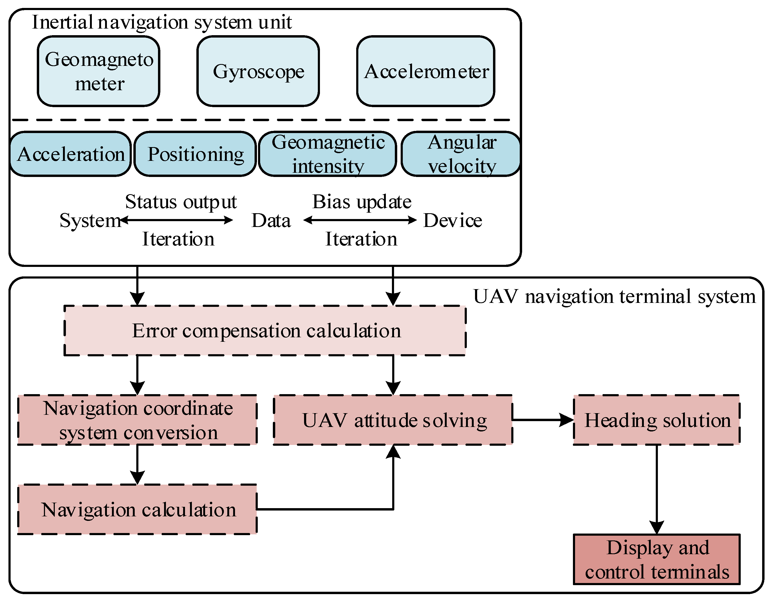
2.3.1. UAV Cluster Cooperative Flight State Update Based on Inertial Navigation

In the complex low-altitude flight environment of urban building obstructions, tunnels, and mountains, global navigation satellite system (GNSS) signals can be rejected, so the acquisition of UAV Z1 may be lost due to signal rejection, and the corresponding θ1, θ2, θ3 information cannot reflect the real-time state of the UAV. In this regard, in order to reduce the impact of GNSS signal rejection on clusters, this paper focuses on updating the flight state of UAVs to achieve accurate and robust inter-cluster flight state estimation.
Inertial navigation systems (INS) do not rely on external GPS signals and can provide continuous, real-time position, velocity, and attitude information in complex low-altitude environments, ensuring high-precision autonomous positioning even when GPS is denied or interfered with. By updating the status of inertial navigation, cluster drones can synchronize their respective motion states, reducing the impact of accumulated errors on collaborative flight. However, due to the advantages of stable sensing data and immunity to external interference in inertial navigation systems, and the fact that accelerometers in inertial navigation devices can measure the acceleration information of unmanned aerial vehicles, gyroscopes can output angular velocity information, and magnetometers can sense geomagnetic intensity, these data are derived from sensing data during the flight of unmanned aerial vehicle clusters, and can be used as a basis for updating the flight status of unmanned aerial vehicle clusters without GNSS signals as an auxiliary navigation. To clarify the source of sensing data, the working principle of the unmanned aerial vehicle’s strapdown inertial navigation system is described in Figure 2.
As shown in Figure 2, the working process of the unmanned aerial vehicle (UAV) strapdown inertial navigation system is as follows: firstly, the accelerometer, gyroscope, and magnetometer of the UAV collect information such as acceleration, angular velocity, pose, and geomagnetic intensity, and then enter the error compensation calculation module. Due to the fact that the data output by the accelerometer and gyroscope are both based on the carrier coordinate system, it is necessary to perform coordinate conversion on the data output by the accelerometer and gyroscope, convert them to the navigation coordinate system, and perform attitude and heading calculations [21,22]. Finally, the navigation information, such as the drone’s position, speed, and attitude angle sensed by the final sensors, is sent to the control and display module of the navigation system for updating and recalling historical status data. However, without GNSS as an auxiliary navigation system, due to the instability and noise characteristics of the inertial navigation unit, the calculated velocity and position errors will diverge over time [23]. By expanding the Taylor expansion of the system dynamics model and ignoring higher-order terms, the attitude quaternion, velocity, and position state update equations of the unmanned aerial vehicle can be obtained by discretizing it:
κ 1 t + 1 = Φ 1 + 1 2 t 0 θ 0 Y 1 t κ 2 t + 1 = θ 1 t + t 0 α 0 t N 0 t κ 3 t + 1 = 1 2 S 0 t t 0 S 0 f 1 t + f 3 t
In Equation (6), κ1, κ2, and κ3 denote the attitude quaternion, UAV velocity, and UAV positional state of the body coordinate system relative to the inertial coordinate system at the next moment; Φ1 denotes the fourth-order unit matrix; t0 denotes the update time step; Y1 denotes the UAV body rotation matrix; and t denotes the current moment of UAV flight-as-a-state data collection.
The zero bias of gyroscopes, accelerometers, and magnetometers is non-static, and for the study of UAV sensors it is generally regarded as a first-order Markov process, which is taken into account in the attitude quaternion, velocity, and position updating together. Combining the updating process of Equation (5), the gyroscope, accelerometer, and magnetometer bias updating equation is described as:
b 1 t = S 0 κ 1 t + 1
b 2 t = κ 2 t + 1 α 0 1 + 1
b 3 t = M N 0 κ 3 t + 1
In Equations (7)–(9), b1, b2, and b3 denote the result of updating the gyroscope, accelerometer, and magnetometer bias in the inertial navigation system.
On the basis of obtaining the updated bias of the inertial navigation device, it is considered as the updated coefficients obeying the mean value of 0 and participating in the rotational projection from the airframe coordinate system to the navigation coordinate system. After completing the projection, the true angular velocity, acceleration, and positional state information of the airframe are solved:
S = b 1 t μ 0 + 1 κ 1
α = κ 2 b 2 t μ 1 + κ 3
P = S + α b 3 t + 1 1 t 0
In Equations (10)–(12), S denotes the true angular velocity value of the UAV as output by the gyroscope; μ0 denotes the three-axis measurement error obeying a mean value of 0; α denotes the true value of the acceleration of the UAV; μ1 denotes the measurement error of the accelerometer; and P denotes the value of the true positional state of the UAV at the next moment of the updated solution.

2.3.2. Global Target Point Localization for UAV Cluster Flights Combined with GPS Positioning

When a drone swarm is performing low-altitude flight missions, navigation and filtering processing are usually performed to accurately obtain its own position and attitude information. During this process, unmanned aerial vehicles (UAVs) perceive their environment by carrying various sensors. The collected data is transmitted to the information system for processing, and the information perception and execution agencies implement corresponding control and operations based on the instructions of the information system, such as adjusting flight attitude, changing flight path, etc. Through this hierarchical structure and interactive approach, drones can achieve accurate positioning and control, ensuring safe distance and global target point determination for drone swarm flight.
The position error of pure inertial navigation accumulates over time. Although it is possible to observe state variables with smaller errors by Taylor expansion of the system dynamics model and ignoring higher-order terms, it is still inevitable to perform correction. The Global Positioning System (GPS) uses the principle of satellite triangulation to achieve positioning, providing global position (longitude, latitude, altitude) in the WGS-84 coordinate system, and errors do not accumulate over time [24]. Therefore, by establishing a GPS drone positioning system through the drone’s own sensors and combining inertial navigation to update data for drone positioning and ranging, the absolute geographic coordinates of the drone’s position and target point can be obtained, and the accumulated error of inertial navigation can be periodically reset to accurately locate the global target point of drone swarm flight.
In the process of UAV cluster low-altitude flight, the core of GPS satellite navigation is the de-expansion and demodulation of navigation information, so as to determine the implementation of pseudo-range, carrier phase, and Doppler shift measurements of the navigation message, and to establish the pseudo-range positioning equation. Setting the satellite clock difference as μ2, tropospheric error as μ3, combining the real angular velocity S, acceleration and position state information α, the basic equation of pseudo-range positioning is established as:
d 0 + P d 1 μ 2 = 2 S α + μ 3 d 2 μ 4 + d 3
In Equation (13), d0 denotes the GPS satellite pseudo-distance; d1 denotes the bias equivalent distance; d2 denotes the GPS satellite clock difference equivalent distance; d3 denotes the actual distance between the receiver and the GPS satellite; and μ4 denotes the sum of the multi-path effect errors during UAV flight.
To further improve the error correction effect, the random error is equated to the clock error, and the error state equation is constructed based on d1 and the clock drift distance change rate to further correct the positioning system error value and locate the global target point of UAV cluster flight:
O = x , y , z = Φ 2 d 0 + P d 1 2 S α + μ 3 d 2 μ 4 d 3 λ 1 + λ 2
In Equation (14), O denotes the UAV cluster flight global target point; (x’, y’, z’) denote the 3D coordinates of the controlled output target point containing the GPS measurement state vector; Φ2 denotes the transfer function matrix vector; and λ1 and λ2 denote the finite energy of the jamming input signal and the UAV desired attitude vector.

2.3.3. CRLB-Based Cross-Path Planning for UAV Clusters Flying at Low Altitude

On the basis of obtaining the real-time state values of the UAV cluster and the flight target point localization, it is necessary to further refine the low-altitude flight environment of the UAV cluster, which is used to conduct the spatial background of cross-path planning [25]. Assuming that the cluster UAV mission scenario is a rectangular region of a certain spatial extent, with the help of Cartesian coordinate system theory, a target attraction potential field and obstacle repulsion potential field are arranged at O as:
h 0 O = e 1 × exp k 1 x x 1 + k 2 y y 1 e 0 z z 1
h 1 O = e φ T × exp k 1 x + x 2 k 2 y + y 2 + e 0 z z 2
In Equations (15)–(16), h0(O) denotes the target attraction potential field; e denotes the reference potential energy strength; κ1 and κ2 denote the potential field skewness between the target attraction potential field and the obstacle repulsion potential field; e0 denotes the basal potential energy strength; (x1, y1, z1) denote the UAV initial position coordinates; h1(O) denotes the obstacle repulsion potential field; (x2, y2, z2) denote the position coordinates of the obstacle distribution that exists within the low-altitude flight environment; φ denotes the initial paths of all the UAVs; and T denotes the time window of the path intersection point.
Regarding the presence of φ in the potential field, there may be a situation of low-altitude flight and cross collision of drone swarms. As a theoretical limit in statistics and signal processing, the Cramér–Rao lower bound (CRLB) represents the minimum variance that can be achieved for unbiased estimation of parameters under given observational data conditions [26]. In the field of drone positioning, CRLB is used to evaluate the theoretical optimal accuracy of positioning systems. Therefore, the minimum error that can be achieved in unbiased estimation under path-crossing collision can be represented by CRLB. Using CRLB as the cost function for φ optimization, the the optimization variables can be described as:
min Γ θ 2 = T q φ s 1 + s 2
In Equation (17), Γ(.) denotes the CRLB seeking trajectory; q denotes the conflict probability of multiple aircraft arriving at the intersection at the same time; s1 and s2 denote the distance between any UAV radiation sources and the time difference between the arrival of the radiation source signals at any UAV master station.
According to the operation logic based on Equation (17), CRLB is related to the estimated position of the current radiation source, the current position of the drone, and the distance between the drone and the radiation source. Therefore, considering the positioning of stationary targets, the current estimated position of the radiation source is correlated with the previous positioning value and affects the CRLB, achieving the optimal positioning accuracy of inertial navigation fused with GPS. At this time, there is no path-crossing conflict in the output of the yaw angle θ2. If the target position error exceeds a certain range, it indicates positioning failure, and the deviation angle θ2 output will still cause cross collision in the flight path. In this regard, taking the trajectory of CRLB as the cost function, the yaw angle of the drone that minimizes the cost function is obtained to calculate the position of the drone on the cross-path at the next moment. This process is repeated until the end flag of the path optimization algorithm is met, that is, q reaches its minimum. At this point, the obtained θ2 of the drone does not have any path-crossing conflicts, effectively achieving low-altitude flight crossing path planning for the drone cluster.

3. Results

3.1. Experimental Environment Description

The selected model for the experiment is DJI MINI4 PRO, with a quantity of 10 units, each equipped with 6 GB of memory. Other configuration parameters are shown in Table 1. In order to verify the practical application effect of the design method in low-altitude flight environment path planning, this experiment used simulation tools in Matlab to set up a three-dimensional grid model containing longitude, latitude, and altitude coordinate information. The grid model has a z-axis range of 0–150 m, an x-axis range of 116.30° E–116.42° E, and a y-axis range of 39.95° N–10.15° N. The number of threat sources (i.e., obstacles) is set to 56, and the obstacle path is adaptively generated in the model based on the overall line of obstacle distribution. The initial distribution path and final target point position of some unmanned aerial vehicles described in the 3D model are approximately (116.39° E, 40.00° N, 50 m), with a longitude resolution of approximately 11 m per 0.001° corresponding to ground spacing, a latitude resolution of ≤0.0003°, and an altitude resolution of 5 m, typically stratified by 5 m at low altitudes. Based on the above content, the initial planning environment for the low-altitude flight cross-path of the drone cluster is shown in Figure 3:
Based on the initial planning environment in Figure 3, the experimental simulation is further described with UAV performance parameters as shown in Table 1.

3.2. Multi-UAV Cooperative Flight Performance Test

The article is based on the fact that multiple drones can perform imaging of low-altitude environmental changes, therefore, the collaborative performance of drones has a certain impact on flight detection results. In order to analyze the collaborative flight performance of multiple drones, the method proposed in this paper was applied to perform low-altitude flight tasks under the same regional conditions at different navigation speeds. The differences in drone navigation time and distance between drones were described; the results are shown in Table 2.
According to Table 2, multiple drones are used in the article for imaging low-altitude environmental changes. During the collaborative flight of multiple drones, it is necessary to ensure consistent navigation time and safe distance between each drone. During the process of flight imaging in this article, with the change in navigation speed, the difference in navigation time of the drone is within 0.5 s. Moreover, the distance between the drones is greater than the set safe distance of 2.3 m. Therefore, the collaborative flight performance of the multiple unmanned aerial vehicles proposed in the article is good, which can jointly complete target monitoring imaging and low-altitude flight tasks at a safe distance and in almost the same time.

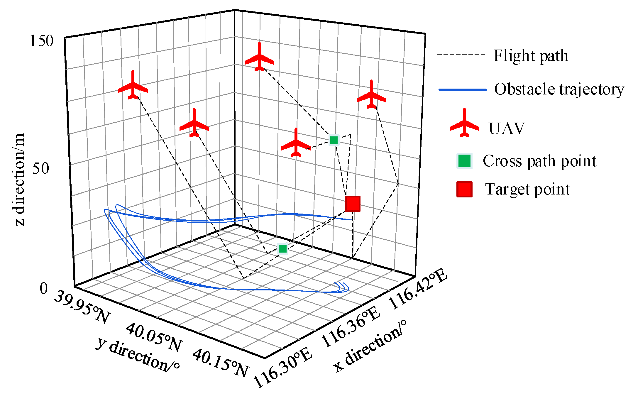
3.3. Testing the Effect of Low-Altitude Flight Cross-Path Planning

To further verify the effectiveness of the design method in low-altitude flight cross-path planning, based on the environment model in Figure 3, two unmanned aerial vehicles A and B with path intersection areas were selected. The initial position of unmanned aerial vehicle A (measured after ascending altitude) was (116.34° E), 40.10° N. The initial position of drone B is (116.36° E, 40.05° N, 75 m), at the given unmanned aerial vehicle cluster inspection target point of (116.39° E, 40.00° N. On the basis of 50 m, the distribution of random obstacles is normalized in the simulation scene to generate the trajectory of movement from Q1 to Q2 and then to Q3. The planning effect after visualizing the application design method using a 3D grid environment model is shown in Figure 4.
According to the results in Figure 4, it can be seen that the distance between the planned path of the drone inspection using the design method and the obstacle trajectory is relatively far, and effective transfer of the intersection space is achieved. In the intersection space after path planning, the distance between the drones in the cluster reaches the safety standard (2.3 m). From this, it can be seen that using the design method, the drone will not collide with obstacles during inspection, and has a certain static obstacle avoidance ability. At the same time, it effectively avoids collisions in the drone’s cross-path, and has good dynamic obstacle avoidance ability.

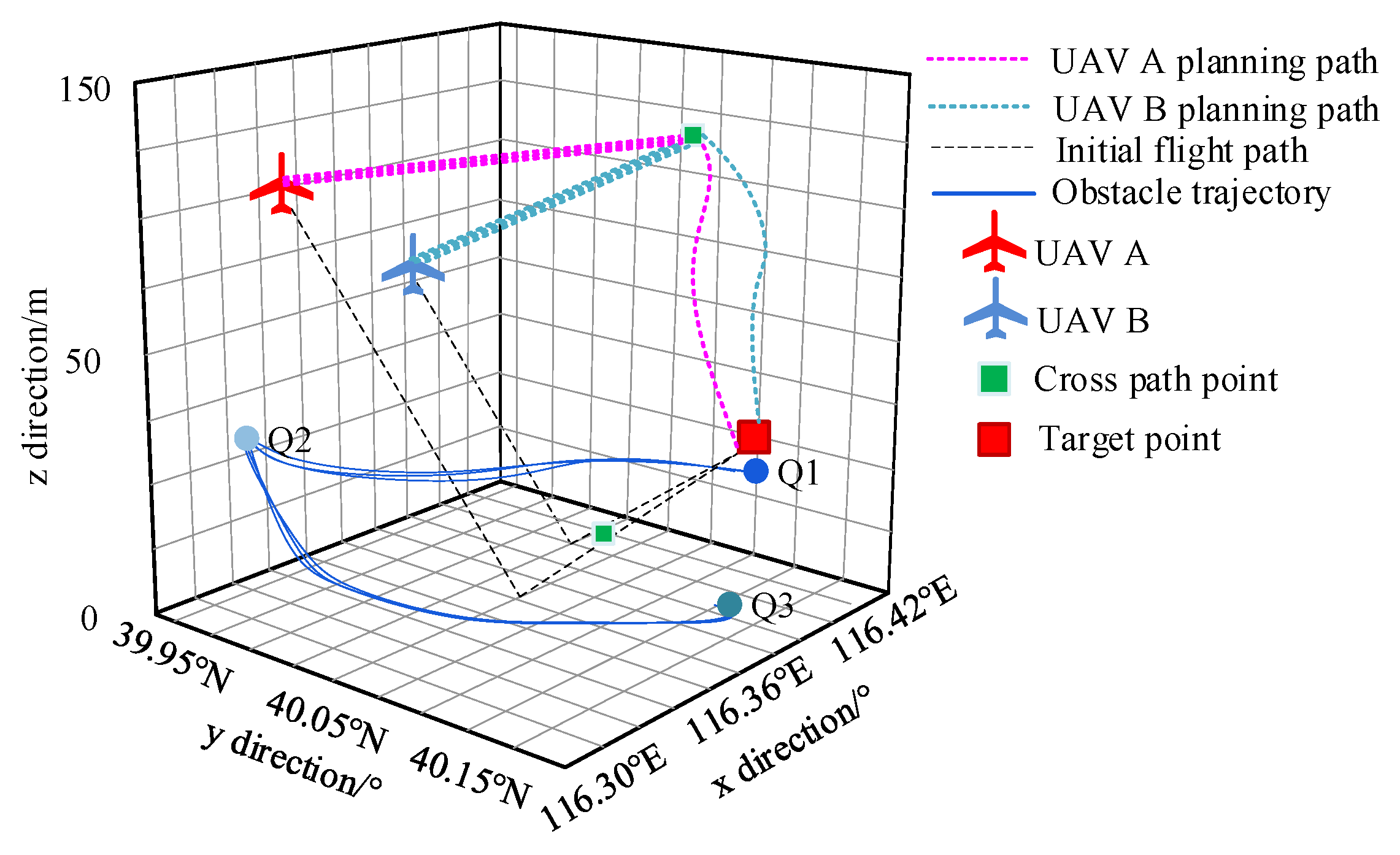
3.4. Comparative Test of UAV Low-Altitude Flight Cross-Path Planning Effect

In order to comprehensively verify the effectiveness of the design method for low-altitude flight cross-path planning of unmanned aerial vehicles, the methods of reference [16] and reference [17] were introduced as comparative methods. Both references [16] and [8] belong to the typical optimization algorithm improvement directions in the field of unmanned aerial vehicle (UAV) path planning in recent years. Reference [16] represents the improvement paradigm based on bio-inspired algorithms, while reference [17] reflects the research trend of multi-strategy fusion particle swarm optimization. The Cauchy perturbation factor and the K-means clustering idea it introduced have been widely applied in solving local optimal problems. Both are highly relevant to the research scenarios of this paper—both are aimed at the complex low-altitude environment, which can clearly highlight the efficiency and real-time performance of the method proposed in this paper in collaborative collision avoidance. The success rate and the number of fitness reductions during path planning iterations (the number of times the optimal solution was generated during the iteration process) were used as evaluation indicators for testing. The specific test results are shown in Table 3.
According to Table 3, in the low-altitude flight cross-path planning of unmanned aerial vehicles, the success rate of the method in reference [17] is the lowest, only 90.54%, indicating poor path optimization of this method and the possibility of cross collision in the planned path. In contrast, although the method proposed in reference [16] increased the success rate to 91.76%, the overall fitness value increased during the iteration process, resulting in a decrease in the number of fitness values and a corresponding decrease in convergence. The use of design methods for cross-path planning resulted in a planning time of 4.36 s and a successful arrival rate of 98.35%. In the process of obtaining the optimal solution for 100 iterations, the cluster collaborative collision avoidance efficiency was 95.39%. The application stability is strong and can effectively solve the problems of cluster collaborative explosion and low efficiency of one-on-one collision avoidance strategies. Moreover, the design method has significant improvements in various performance indicators compared to the other two algorithms, indicating the superiority of the design method in cluster unmanned flight cross-path planning.

4. Conclusions

The article proposes a low-altitude flight cross-path planning for drone clusters based on inertial navigation combined with GPS positioning, aiming to break through and solve three key contradictions in the large-scale application of drones: resolving the contradiction between limited airspace and infinite scheduling requirements in the spatial dimension; balancing the contradiction between planning time and collaborative response in the time dimension; and coordinating the contradiction between collaborative optimization and distributed execution at the system dimension. The experimental results show that using the design method, the drone will not collide with obstacles during inspection, and has a certain static obstacle avoidance ability. At the same time, it effectively avoids collisions in the drone’s cross-path, and has good dynamic obstacle avoidance ability. It has certain advantages in cluster unmanned flight cross-path planning.

Author Contributions

Conceptualization, X.Y. and M.Z.; methodology, X.Y., M.Z. and P.Y.; software, X.Y., M.Z. and P.Y.; validation, X.Y., M.Z. and P.Y.; formal analysis, X.Y., M.Z., P.Y., Q.W, and D.X.; investigation, X.Y. and M.Z.; resources, M.Z. and P.Y.; writing—original draft, X.Y., M.Z. and P.Y.; writing—review and editing, Q.W., D.X. and Y.B.B.; visualization, X.Y. and M.Z.; supervision, M.Z. and P.Y.; project administration, D.X.; funding acquisition, Q.W. All authors have read and agreed to the published version of the manuscript.

Funding

National Natural Science Foundation of China under grant 42401521, Henan Key Research and Development Program under grant 241111320700, Guangdong Basic and Applied Basic Research Foundation under grant 2024A1515011866, Central Guidance on Local Science and Technology Development Fund of Shanxi Province under grant YDZJSX20231D005.

Institutional Review Board Statement

Not applicable.

Informed Consent Statement

Not applicable.

Data Availability Statement

Data are contained within the article.

Acknowledgments

Thanks to Chen Dong of Laser Processing Laboratory of Wuhan University Student Engineering Training and Innovation Practice Center for providing equipment support for this paper.

Conflicts of Interest

The authors declare no conflicts of interest.

References

  1. Saadi, A.A.; Soukane, A.; Meraihi, Y.; Gabis, A.B.; Mirjalili, S.; Ramdane-Cherif, A. Uav path planning using optimization approaches: A survey. Arch. Comput. Methods Eng. 2022, 29, 4233–4284. [Google Scholar] [CrossRef]
  2. Shi, Z.; Zuo, Z.; Dong, R. Low-altitude scaled similarity analysis and flight tests of near space airships with pressure resistance mechanism. Adv. Space Res. 2023, 72, 2324–2335. [Google Scholar] [CrossRef]
  3. Winkenbach, M.; Spinier, S.; Pachon, J.; Konduri, K. Introduction to the special issue on machine learning methods and applications in large-scale route planning problems. Transp. Sci. 2024, 58, 1–7. [Google Scholar] [CrossRef]
  4. Zhan, H.; Zhang, Y.; Huang, J.; Song, Y.; Xing, L.; Wu, J.; Gao, Z. A reinforcement learning-based evolutionary algorithm for the unmanned aerial vehicles maritime search and rescue path planning problem considering multiple rescue centers. Memetic Comput. 2024, 16, 373–386. [Google Scholar] [CrossRef]
  5. Roncolini, F.; Galante, G.; Quaranta, G.; Masarati, P. Constrained path planning for manned–unmanned rotorcraft teaming in emergency medical service missions. CEAS Aeronaut. J. 2024, 15, 619–641. [Google Scholar] [CrossRef]
  6. Li, Y.; Zhang, L.; Cai, B.; Liang, Y. Unified path planning for composite UAVs via Fermat point-based grouping particle swarm optimization. Aerosp. Sci. Technol. 2024, 148, 109088. [Google Scholar] [CrossRef]
  7. Yaqoob, A.; Yuan, Z.; Muntean, G.-M. A UAV-Centric Improved Soft Actor-Critic Algorithm for QoE-Focused Aerial Video Streaming. IEEE Trans. Veh. Technol. 2024, 73, 13498–13512. [Google Scholar] [CrossRef]
  8. Sabuwala, N.A.; Daruwala, R.D. An approach to enhance the security of unmanned aerial vehicles (UAVs). J. Supercomput. 2024, 80, 9609–9639. [Google Scholar] [CrossRef]
  9. Yao, P.; Yang, G.; Peng, X.; Peng, J. An Initial Alignment Algorithm Based on RSKF Single-Axis Rotational Inertial Navigation System. IEEE Sens. J. 2024, 24, 30749–30757. [Google Scholar] [CrossRef]
  10. Jiang, Y.; Xu, X.-X.; Zheng, M.-Y.; Zhan, Z.-H. Evolutionary computation for unmanned aerial vehicle path planning: A survey. Artif. Intell. Rev. 2024, 57, 267. [Google Scholar] [CrossRef]
  11. Rhudy, M.B.; Fravolini, M.L.; Napolitano, M.R. GPS-free roll and pitch estimation through pressure altitude aided inertial navigation system for a jet aircraft. Aerosp. Sci. Technol. 2024, 146, 108975. [Google Scholar] [CrossRef]
  12. Kim, N.; Macciotta, R.; Jun, B. Time series analysis of slope displacements using uav photogrammetry and its relationship with rainfall intensity. Landslides 2024, 21, 1673–1689. [Google Scholar] [CrossRef]
  13. Meng, Q.; Qian, C.; Sun, Z.Y.; Zhao, S. Autonomous parking method based on improved A* algorithm and model predictive control: Autonomous parking method. Nonlinear Dyn. 2025, 113, 6839–6862. [Google Scholar] [CrossRef]
  14. Sabzekar, S.; Samadzad, M.; Mehditabrizi, A.; Tak, A.N. A Deep Reinforcement Learning Approach for UAV Path Planning Incorporating Vehicle Dynamics with Acceleration Control. Unmanned Syst. 2024, 12, 477–498. [Google Scholar] [CrossRef]
  15. Bo, L.; Wang, S.; Ge, C.; Fan, Q.; Temuer, C. Bi-level intelligent dynamic path planning for an UAV in low-altitude complex urban environment. Trans. Inst. Meas. Control 2024, 46, 39–57. [Google Scholar]
  16. Wang, S.; Zhu, D.; Zhou, C.; Sun, G. Improved grey wolf algorithm based on dynamic weight and logistic mapping for safe path planning of UAV low-altitude penetration. J. Supercomput. 2024, 80, 25818–25852. [Google Scholar] [CrossRef]
  17. Ye, Z.; Li, H.; Wei, W. Improved particle swarm optimization based on multi-strategy fusion for UAV path planning. Int. J. Intell. Comput. Cybern. 2024, 17, 213–235. [Google Scholar] [CrossRef]
  18. Cheng, L.; Ling, G.; Liu, F.; Ge, M.-F. Application of uniform experimental design theory to multi-strategy improved sparrow search algorithm for UAV path planning. Expert Syst. Appl. 2024, 255, 124849. [Google Scholar] [CrossRef]
  19. Cao, Q.; Kang, W.; Ma, R.; Liu, G.; Chang, L. DDQN path planning for unmanned aerial underwater vehicle (UAUV) in underwater acoustic sensor network. Wirel. Netw. 2024, 30, 5655–5667. [Google Scholar] [CrossRef]
  20. Beishenalieva, A.; Yoo, S.-J. UAV Path Planning for Data Gathering in Wireless Sensor Networks: Spatial and Temporal Substate-Based Q-Learning. IEEE Internet Things J. 2024, 11, 9572–9586. [Google Scholar] [CrossRef]
  21. He, Q.; He, G.; Yang, H.; Chen, S.; Wang, J.; Liu, S. In-Motion Rapid and Robust Heading Alignment of Low-Cost Inertial Measurement Units Using Position Loci for Indoor Navigation. IEEE Sens. J. 2024, 24, 19454–19465. [Google Scholar] [CrossRef]
  22. Hashim, H.A.; Eltoukhy, A.E.E.; Vamvoudakis, K.G. UWB Ranging and IMU Data Fusion: Overview and Nonlinear Stochastic Filter for Inertial Navigation. IEEE Trans. Intell. Transp. Syst. 2024, 25, 359–369. [Google Scholar] [CrossRef]
  23. Fornasier, A.; van Goor, P.; Allak, E.; Mahony, R.; Weiss, S. MSCEqF: A Multi State Constraint Equivariant Filter for Vision-Aided Inertial Navigation. IEEE Robot. Autom. Lett. 2024, 9, 731–738. [Google Scholar] [CrossRef]
  24. Ji, M.; Ren, G.; Zhang, H.; Ren, R. Collaborative positioning for emergency rescuers based on INS, GPS and ZigBee. Phys. Scr. 2024, 99, 065530. [Google Scholar] [CrossRef]
  25. Knight, J.; Burningham, H.; Griffiths, D.; Yao, Y. Coastal boulder movement on a rocky shoreline in northwest ireland from repeat uav surveys using structure from motion photogrammetry. Geomorphology 2023, 440, 108883. [Google Scholar] [CrossRef]
  26. Rahman, M.F.A.; Din, A.H.M.; Hamden, M.H.; Mahmud, M.R.; Rasib, A.W. Developing a near-seamless tidal datum by integrating tidal and satellite altimetry data with a Digital Elevation Model for maritime boundary delimitation. Int. J. Remote Sens. 2024, 45, 8827–8858. [Google Scholar] [CrossRef]
Figure 1. Spatial rasterization structure of low-altitude flight environment for UAV cluster.
Electronics 14 02877 g001
Figure 2. Working principle of unmanned aerial vehicle strapdown inertial navigation system.
Electronics 14 02877 g002
Figure 3. Initial planning environment for UAV cluster low-altitude flight cross-paths.
Electronics 14 02877 g003
Figure 4. Effect of UAV low-altitude flight cross-path planning.
Electronics 14 02877 g004
Table 1. UAV cluster low-altitude flight cross-path planning experimental parameters.
Parameter CategoryParameterNumerical Description
Simulation parametersStandard deviation of pseudo-range measurement error1.5 m
Doppler velocity measurement error0.14 m/s
Lower limit of CRLB position error1.2 m (horizontal), 2.0 m (vertical)
Zero bias of accelerometer0.012 m/s
Inertial error accumulation rate0.01 m/s
Conflict detection threshold3 s, conflict probability < 1%
Safe distance for cooperative flight of drones2.3 m
Performance parameters of unmanned aerial vehiclesmain camera48 million pixels
Maximum payload50 g
Battery capacity18.96/(W·h)
Max flight time45 min
Weight249 g
Table 2. Multi-UAV cooperative flight performance test results.
Sailing Speed m/sSailing Time Difference/sUAV Synergy Distance/m
150.311.62
180.282.45
210.033.61
240.492.04
270.052.51
300.191.92
330.011.08
350.001.75
Table 3. Comparison test results of UAV low-altitude flight cross-path planning effect.
Planning MethodsPlanned Runtime/sTarget Achievement Success Rate/%Number of Times the Fitness of the Planned Path Is Reduced/TimeCollaborative Collision Avoidance Efficiency/%
Design method4.3698.3510095.39
Literature [16] method7.5291.764689.68
Literature [17] method6.6890.547185.49
Disclaimer/Publisher’s Note: The statements, opinions and data contained in all publications are solely those of the individual author(s) and contributor(s) and not of MDPI and/or the editor(s). MDPI and/or the editor(s) disclaim responsibility for any injury to people or property resulting from any ideas, methods, instructions or products referred to in the content.

