Article

Research on Circulating-Current Suppression Strategy of MMC Based on Passivity-Based Integral Sliding Mode Control for Multiphase Wind Power Grid-Connected Systems

by
Wei Zhang
1,*,
Jianying Li
2,
Mai Zhang
1,
Xiuhai Yang
1 and
Dingai Zhong
1
1
School of Transportation and Electrical Engineering, Hunan University of Technology, Zhuzhou 412007, China
2
School of Computer and Electrical Engineering, Hunan University of Arts and Science, Changde 415000, China
*
Author to whom correspondence should be addressed.
Electronics 2025, 14(13), 2722; https://doi.org/10.3390/electronics14132722
Submission received: 14 June 2025 / Revised: 28 June 2025 / Accepted: 3 July 2025 / Published: 5 July 2025

Abstract

To deal with the interphase circulating-current problem of modular multilevel converters (MMCs) in multiphase wind power systems, a cooperative circulating-current suppression strategy based on a second-order generalized integrator (SOGI) and passivity-based control–integral sliding mode control (PBC-ISMC) is proposed in this paper. Firstly, a multiphase permanent magnet direct-drive wind power system topology without a step-up transformer is established. On this basis, SOGI is utilized to construct a circulating current extractor, which is utilized to accurately extract the double-frequency component in the circulating current, and, at the same time, effectively filter out the DC components and high-frequency noise. Secondly, passivity-based control (PBC), with its fast energy dissipation, and integral sliding mode control (ISMC), with its strong robustness, are combined to construct the PBC-ISMC circulating-current suppressor, which realizes the nonlinear decoupling and dynamic immunity of the circulating-current model. Finally, simulation results demonstrate that the proposed strategy significantly reduces the harmonic content of the circulating current, optimizes both the bridge-arm current and output current, and achieves superior suppression performance and dynamic response compared to traditional methods, thereby effectively enhancing system power quality and operational reliability.

1. Introduction

Wind energy, as a renewable energy source, has grown faster than all other renewable energy sources in recent years due to its cleanliness, abundant reserves, and relatively mature technology [1,2,3,4,5,6]. Driven by the need to meet increasing energy demands and environmental goals, the role of high-power multimegawatt full-power wind energy conversion systems (wind energy conversion systems, WECSs) is becoming increasingly significant [7,8,9]. Multiphase generators have a large number of windings, high fault tolerance, a small stator current for the same capacity, and are low-power-level devices which can be used with a low-voltage and offer high-power generation, and at the same time have a higher degree of freedom of control and design flexibility—many advantages that make them more and more popular in wind power generation [10,11,12]. Modular multilevel converters (MMCs) have a strong expandability compared with traditional grid-connected inverters by virtue of their modular design structure. Moreover, they can significantly improve the power quality [13], reduce the device switching frequency [14], and they have unique advantages in high-voltage and high-power energy-conversion situations [15]; thus, they have been increasingly researched and applied in the fields of flexible DC transmission [16], motor drives [17], and new energy grid connections [18].
In this paper, we study an MMC-based multiphase wind power system to construct a high-voltage permanent magnet direct-drive wind power converter system without a step-up transformer. Multiphase wind turbines capture large-scale wind energy after rectification—through a multimodule cascade to realize a boost and for grid connection—so as to improve grid voltage matching and at the same time optimize output harmonic characteristics, which effectively fits the development trend of large-scale wind power equipment exhibiting a high power density and high grid compatibility [19,20]. However, during the normal grid-connected operation of an MMC, the continuous charging and discharging of its internal capacitance can cause voltage imbalance and phase-to-phase circulating current, owing to the fact that a large number of its bridge-arm submodules are always in the process of casting and cutting [21,22]. The presence of a loop current not only exacerbates the losses in the switching components of the system, but also produces distortion in the bridge-arm current waveform and reduces the power quality. Determining how to efficiently suppress the interphase circulation of MMCs has also become a pertinent issue, widely studied by many scholars [23]. References [24,25] designed a proportional–integral (PI) controller to realize the circulating-current suppression effect from an energy-based perspective. The controller is simple to realize in principle, but the control parameters are susceptible to the external environment, and the system stability and control accuracy are limited. Reference [26] proposed a highly generalized universal circulating-current suppression (UCCS) strategy suitable for MMCs with any number of phases, which suppresses circulating currents by real-time detection and calculation of bridge-arm current differentials, but involves a high computational load and is susceptible to high-frequency noise. Reference [27] proposed a trap-based circulating-current extraction method combined with a PR controller that is simple, easy to implement, and effective in suppression, but has limited system stability. Reference [28] improved system stability and loop current suppression speed by adding proportional negative feedback of bridge-arm current to the PR suppressor, but increases computational complexity. Reference [29] introduced a PIR-based circulating-current suppressor that enhances steady-state suppression by adding an integral link to the PR structure but which has limited frequency adaptability and suboptimal dynamic performance. Reference [30] proposed a PI + repetitive control scheme that enhances harmonic suppression by combining the PI’s dynamic response with the repetitive controller’s steady-state performance, offering easy implementation for both single-phase and three-phase MMCs. Reference [31] incorporated loop current hysteresis control into MMC modulation using redundant levels to suppress the loop current, offering a simple approach but compromising output-voltage waveform quality. Reference [32] introduced additional submodules in the bridge arm controlled by differential-free beat control to suppress circulating harmonics and improve voltage quality, but this heavily depends on system parameter determinism. Reference [33] proposed a dual-mode circulating-current suppression method combining PWM and NLM, enabling two submodules per bridge arm to operate in PWM mode for the accurate tracking of the suppression voltage reference. Reference [34] proposed a sensor-less circulating current suppression method that reduces cost and complexity but cannot control submodule voltage averages or bridge-arm energy balance without a current reference. Reference [35] proposed a novel circulating-current suppression strategy (VI-SMC-CCS) based on virtual impedance and sliding mode control, which effectively suppresses the double-frequency component of the circulating current while offering good dynamic response and robustness. However, the method involves high computational complexity and requires precise parameter tuning. Reference [36] combined fuzzy control with PI control, where the PI parameters are self-tuned via fuzzy logic to enhance system robustness. However, the dynamic performance of the circulating-current control was not effectively verified.
Given the widening applications of MMCs, efficient suppression of their interphase circulating currents has become a critical research focus. This paper studies an MMC system within a multiphase wind power grid-connected context, briefly analyzing its working principle and circulating-current generation. It employs SOGI to separate the circulating current to extract the AC double-frequency component and proposes a passivity-based integral sliding mode control (PBC-ISMC) method for circulating-current suppression. This method combines the rapid response and disturbance immunity of passivity-based control [37,38] with the strong robustness and excellent dynamic performance of integral sliding mode control [39,40]. Finally, simulations validate the effectiveness and superiority of the proposed circulating-current suppression method.

2. Structure and Mathematical Model of MMC-Based Multiphase Wind Power Generation System

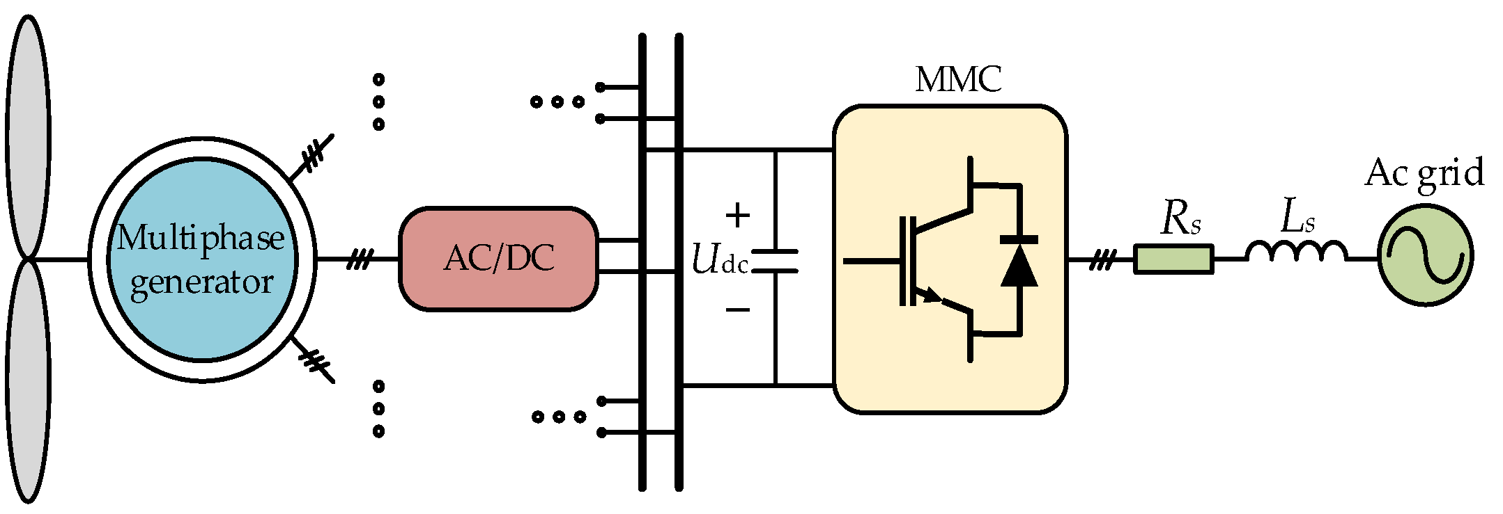
2.1. System Topology

The structure of the MMC-based multiphase wind power generation system is shown in Figure 1. It consists of a wind turbine, a multiphase permanent magnet synchronous generator, a machine-side converter, and a grid-side converter. The machine-side converter functions as an AC/DC rectifier, while the grid-side converter is implemented using an MMC.
The constructed system aligns with the development trend of large-scale wind power. The MMC, serving as the grid-side converter, enables stable grid connection at high voltage levels without requiring additional filters or step-up transformers. The number of phases in the multiphase motor is an integer multiple of three. The output of the machine-side rectifier is connected to the high-voltage DC bus, and its DC-side output voltage, Uo, along with the number of motor phases, nphase, jointly determines the high-voltage DC bus voltage, Udc, as expressed by the following relationship:
U dc = U o n phase 3
As the main focus of this paper is on the grid-connected side, the front-end circuit is replaced by a DC bus, and the grid-connected MMC is analyzed in detail below. The topology of the three-phase grid-connected MMC system is shown in Figure 2. Its main circuit consists of three phases and six bridge arms, with each arm composed of N submodules, a bridge-arm inductor L0, and an equivalent resistance R0 connected in series. This forms a typical three-phase system with an N + 1 level output. The AC output is taken between the upper and lower bridge arms and integrated into the grid. Udc represents the DC bus voltage, and o denotes the reference potential between the positive and negative poles of the common DC bus.
According to Figure 2, Udc is the DC-side bus voltage, defining j = a, b, c three-phase; upj and unj are expressed as the upper and lower bridge arm voltages of phase j, respectively; and ipj and inj are the upper and lower bridge arm currents of phase j, respectively. uvj is the j-phase output voltage of the MMC, and ivj is the j-phase output current; usj is the j-phase phase voltage of the power grid, and isj is the phase current of the power grid; LS and RS are the grid-side filter inductance and equivalent resistance, respectively.

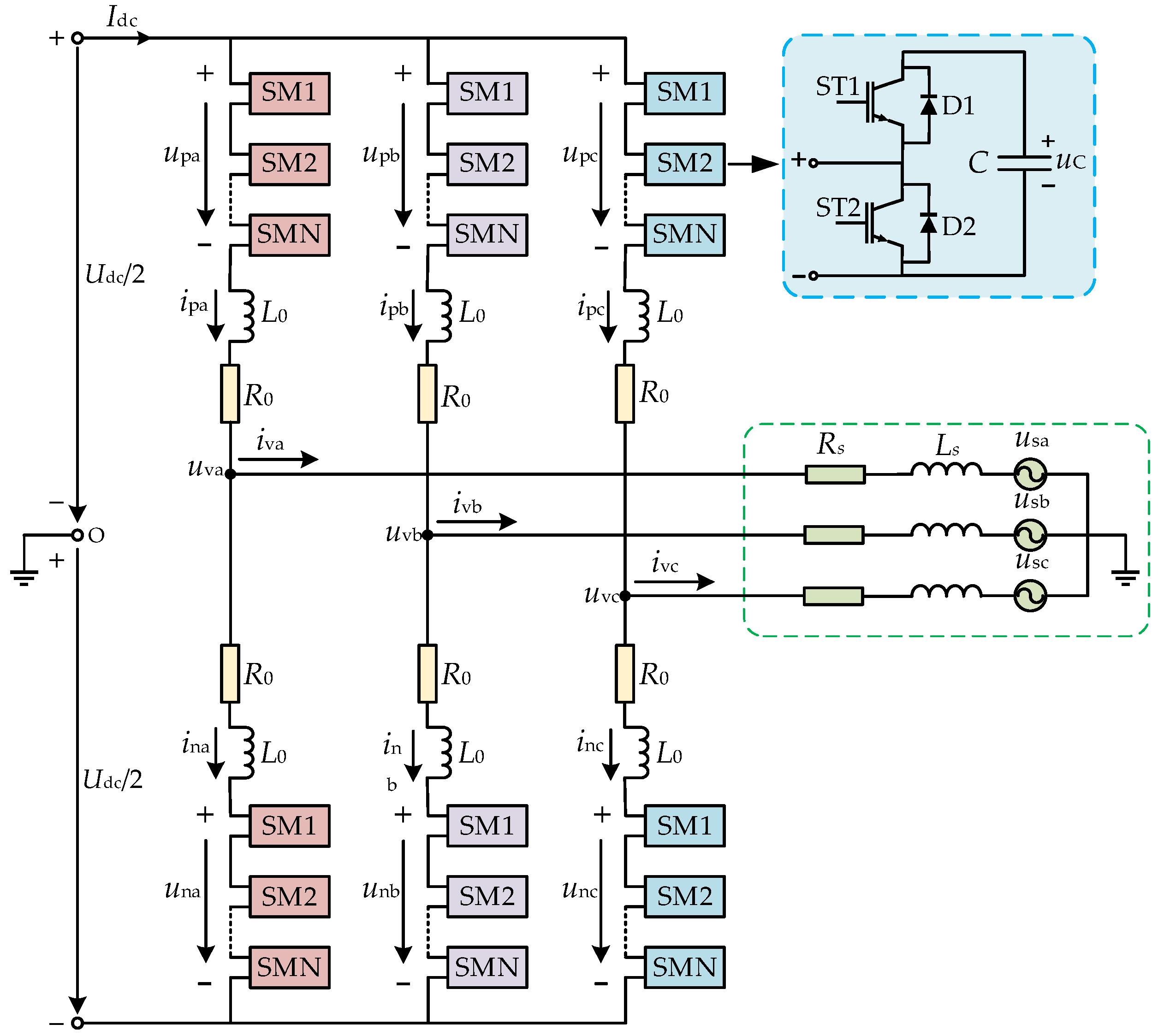
2.2. Mathematical Modeling of Grid-Connected MMC and Analysis of Internal Circulation Generation Mechanism

To establish the steady-state mathematical model and circulating current model of the three-phase grid-connected MMC, the following assumptions are made: the system operates under a three-phase symmetrical condition; switching losses are neglected; the AC currents on the grid side are symmetrically distributed between the upper and lower bridge arms; and the DC bus voltage Udc, is constant and unchanged. Based on these assumptions, the internal and external operating characteristics of the grid-connected MMC are analyzed. In the ideal case, the submodule’s rated voltage value is USM = Udc/N, and the phase-to-phase circulating-current icirj of the MMC is only the DC component Idc/3. However, in practice, due to the alternating switching of submodules, the internal capacitors charge and discharge unevenly, causing the actual capacitor voltage to deviate from the rated value, resulting in the actual output voltage of the three-phase unit not always being the same, which in turn generates an internal circulating current. Referring to Figure 2 and applying Kirchhoff’s laws (KVL and KCL), we obtain
U dc 2 u pj R 0 i pj L 0 d i pj d t L sj d i vj d t = u sj U dc 2 + u nj + R 0 i nj + L 0 d i nj d t L sj d i vj d t = u sj
i pj = i cirj + 1 2 i vj i nj = i cirj 1 2 i vj
where ivj = ipjinj, and the two terms in Equation (3) are added together to obtain the expression for the circulation as follows:
i cirj = i pj + i nj 2
The differential mode voltage between the upper and lower bridge arms is defined as udiffj and common-mode voltage as ucomj with the following expression:
u diffj = u nj u pj 2 u comj = u nj + u pj 2
From Equation (2), the two equations are summed, differed, and simplified to obtain the differential mode and common mode equations characterizing the dynamic characteristics of the AC and DC sides of the MMC as follows:
u sj = u diffj R 0 2 i vj L sj + L 0 2 d i vj d t U dc 2 = u comj + R 0 i cirj + L 0 d i cirj d t
where the differential mode equations are the characteristic equations characterizing the input and output of the MMC, and the common-mode equations are the circulation model of the MMC. The voltage drop across the bridge arm impedance induced by the circulating current is defined as ucirj, and one obtains
u cirj = R i cirj + L d i cirj d t = U dc 2 u comj
Combining Equations (6) and (7), the reference voltage expressions for the upper and lower bridge arms are derived as follows:
u pj _ ref = U dc 2 u diffj u cirj _ ref u nj _ ref = U dc 2 + u diffj u cirj _ ref
where upj_ref, unj_ref are the reference voltages of the upper and lower bridge arms, respectively, and ucirj_ref is the reference value of the unbalance voltage drop ucirj caused by the circulating current on the bridge arm impedance. From Equation (8), the voltage drop due to the circulating current can be eliminated by subtracting ucirj_ref from the reference voltage command of the upper and lower bridge arms, without affecting the output of the AC side of the MMC.
The existing literature shows that, based on instantaneous energy conservation in the bridge arm and the average switching function, the internal circulating current icirj in a normally operating three-phase MMC mainly comprises a DC component Idc/3 and a double-frequency AC component with negative phase sequence. Neglecting high-frequency harmonics, the three-phase circulating current of the MMC can be expressed as follows:
i cira = I dc 3 + I 2 f cos ( 2 ω t + θ 0 ) i cirb = I dc 3 + I 2 f cos ( 2 ω t + 2 π 3 + θ 0 ) i circ = I dc 3 + I 2 f cos ( 2 ω t 2 π 3 + θ 0 )
where I2f is the amplitude of the two-frequency circulating current and θ0 is the initial phase of the circulating current.

3. Study of Circulation Suppression Strategies

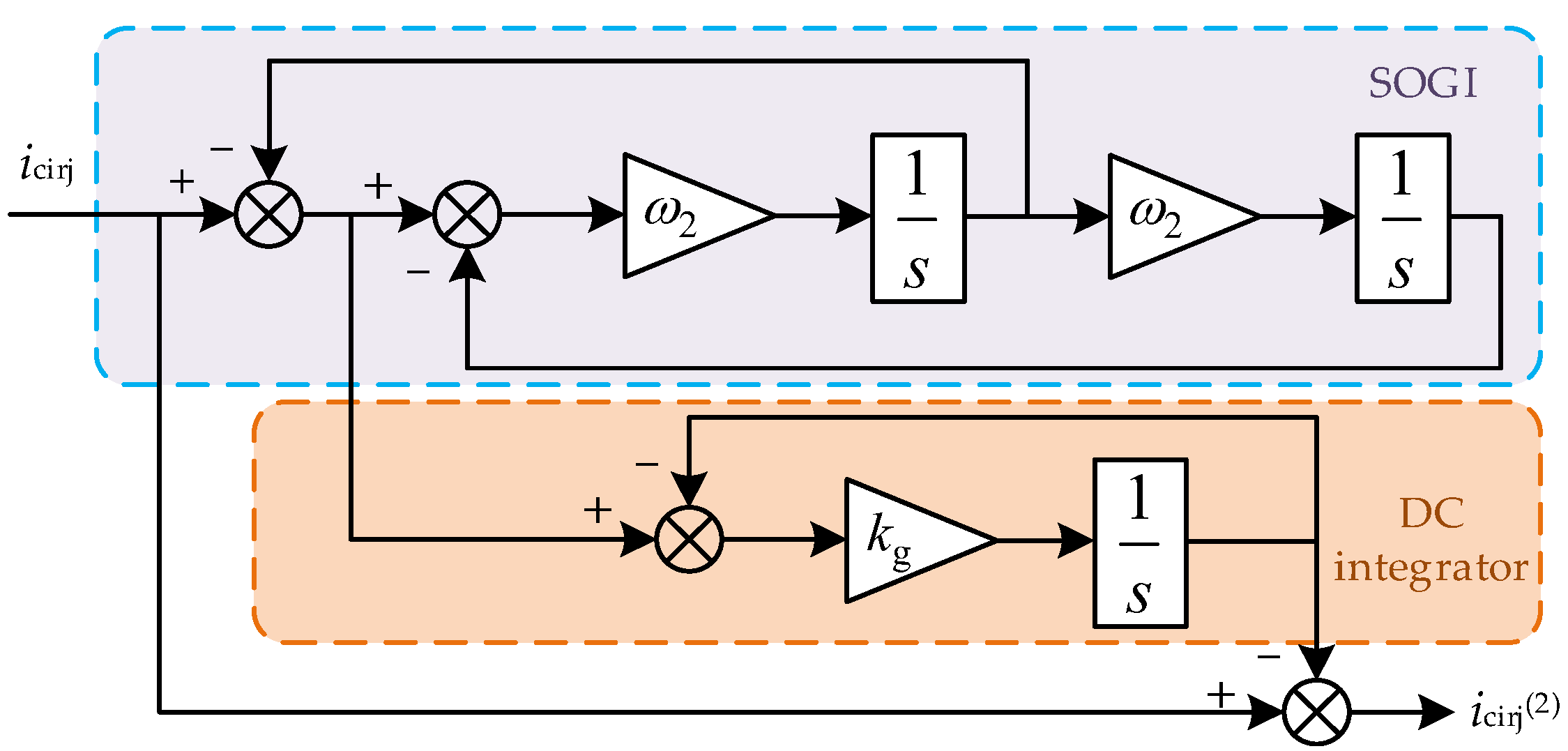
3.1. SOGI-Based Extraction of Twofold Frequency Circulating-Current Components

With reference to the analysis of the circulating current inside the MMC in the previous section, it can be seen that the circulating current contains both DC and AC components, and the DC component plays the role of balancing the three-phase power and transmitting the active power, so it does not need to be suppressed. On the other hand, the two-fold AC component increases the energy loss of the bridge arm, reduces the voltage quality, and causes the output current distortion, so it needs to be suppressed.
In order to more accurately and efficiently obtain the two-octave components in the circulating current, this paper constructs a circulating-current extractor based on the second-order generalized integrator (SOGI). The SOGI has superior dynamic performance and is able to effectively filter out the high-frequency components and suppress the noise. The block diagram of the SOGI-based harmonic separator is shown in Figure 3.
As shown in Figure 3, the circulating current separator is composed of the SOGI and the DC integrator, and the three-phase circulating current icirj obtains the two-frequency AC component after the SOGI. It is then differed from the initial circulating current to obtain the error output. The output value here includes the high-frequency even component and the DC component of the loop current. The error value is then passed through a DC integrator, which filters out the high-frequency component to obtain the DC component of the loop current. Finally, the original loop current is differenced from it to obtain the harmonic components of the two-octave loop current. The transfer function of this circulation extraction method is as follows:
G ( s ) = 1 k g s + k g + ω 2 s s 2 + ω 2 s + ω 2 2 · k g s + k g
where ω2 is the harmonic separation point of two times frequency, and ω2 = 2ω0 = 4πf0, f0 is the rated frequency of power grid. kg is the gain of the DC integrator. Its size determines the dynamic performance of the circulating harmonic separator, and kg is too small to reduce the low-frequency damping effect, while a too-large kg will make the low-frequency damping too large and also affect the separation accuracy. Figure 4 shows the Bode diagram of the transfer function when kg takes different values. Considering the system performance, combined with the Bode diagram, kg = 20 is taken in this paper.

3.2. Passivity Analysis of MMC Circulation Models

In the context of this study, the traditional PI controller was selected as the primary benchmark for comparative analysis. PI control is widely adopted in industrial MMC systems due to its simplicity and ease of implementation. However, it has inherent limitations, such as poor adaptability to parameter changes, limited robustness under multiphase conditions, and poor transient performance. These shortcomings provide a reasonable basis for developing advanced control strategies. Therefore, PI control serves as the representative and practical baseline for comparison in this study. Existing droop control and passive damping are also common techniques, but they typically target different objectives (such as power distribution or resonance suppression) and cannot be directly compared in the context of suppressing circulating currents in multiphase MMC systems. Future research will consider further evaluating such alternative approaches. The following sections detail the PBC-ISMC circulating current suppression method proposed in this paper.
Passivity-based control (PBC) is an energy-based control method that introduces nonlinear damping based on the system’s inherent structure. By reconfiguring system energy, it drives the system to a stable state. Theory and practice show that, under normal conditions, changes in physical quantities reflect energy variations. Therefore, with proper energy regulation, physical quantities can converge to the desired control effect.
As the voltage and current parameters in the circulating-current model of the MMC system are time-varying AC quantities, it is difficult to analyze and control them directly. The phase sequence of the circulating current is a negative sequence. First of all, the negative sequence abc-dq transformation is carried out on it. By combining Equations (6) and (7), the circulating current model of MMC in the dq rotating coordinate frame can be obtained as follows:
u cir d = L 0 d i cir d d t + R 0 i cir d + 2 ω L 0 i cir q u cir q = L 0 d i cir q d t + R 0 i cir q 2 ω L 0 i cir d
Based on Equation (11), the transfer function model of the MMC circulation model in the dq negative-order rotational coordinate system is derived. It is shown in Figure 5.
Figure 5 shows that there is coupling between ucird, ucirq, and icird, icirq. In the traditional circulating current suppression method, a PI regulator is used to decouple. However, its parameters are difficult to adjust and easily affected by external disturbances, which is unfavorable for the precise control of the system. In this paper, a passive control method is used to realize nonlinear decoupling and effectively suppress the circulating current. To simplify the analysis of the passive characteristics of the circulation model, Equation (11) is rewritten in the form of a matrix as follows:
u cir d u cir q = L 0 0 0 L 0 d i cir d d t d i cir q d t + R 0 0 0 R 0 i cir d i cir q + 0 2 ω L 0 2 ω L 0 0 i cir d i cir q
Then, Equation (12) is written in the form of the EL model:
M x ˙ + R x + J x = u
The values in Equation (13) are expressed as
M = L 0 0 0 L 0 ; R = R 0 0 0 R 0 ; x = i cir d i cir q J = 0 2 ω L 0 2 ω L 0 0 ; u = u cir d u cir q
where M is a positive definite diagonal energy storage matrix, R is a semi-positive definite dissipation matrix, x is a system state variable, J is a system interconnection matrix, and u is a system input vector.
In general, for a given input–output system:
x ˙ = f ( x , u ) y = h ( x ) , x ( 0 ) = x 0 R n
where x is the system state variable, u is the system input, y is the output, and f is the Lipschitz function. For this system, if any one of the following dissipation inequalities is satisfied when t > 0, then it can be shown to be passive.
H ( x ( t ) ) H ( x ( 0 ) ) 0 t y u T d τ 0 t Q ( x ) d τ
H ˙ ( x ) y u T Q ( x )
In Equations (16) and (17), H(x) is a continuous and differentiable semi-positive definite energy storage function and Q(x) is positive definite.
For the MMC circulation model, the energy storage function is chosen to be
V ( x ) = 1 2 x T M x
Taking the derivative of it gives
V ˙ ( x ) = x T M d x d t = x T ( u J x R x ) = x T u x T R x
Letting y = x and the positive definite function Q(x) = xTRx, Equation (17) can be obtained. That is, this circulation model satisfies the passivity condition and the circulation can be controlled by the passivity method.

3.3. Passive-Integral Sliding Mode Circulation Suppressor Design

When the MMC is in normal operation, the target equilibrium point of the dq-axis component of the interphase circulation is assumed to be
x ref = i cir d ref i cir d ref
where icirdref and icirdref are the desired equilibrium points of the d- and q-axis circulation, respectively, which are the circulation reference values. At this point, the error in the state variable of the system is
x e = x x ref = i cir d i cir d ref i cir q i cir q ref
By substituting Equation (21) into Equation (13), the following can be obtained:
M x ˙ e + R x e + J x e = u M x ˙ ref R x ref J x ref
At this point, we let the energy error function be
V e ( x ) = 1 2 x e T M x e
to achieve system converge quickly to the desired equilibrium point, even if Ve(x) converges quickly to 0. The energy dissipation process of this passive system is accelerated by means of injected damping in order to enhance the system response. We take the injected damping dissipation term as
R d x e = ( R + R a ) x e
where Ra is the positive definite matrix of the damping injected here, and Rd is the new positive definite matrix after the damping injection, denoted, respectively, as
R a = R a 1 0 0 R a 2 ; R d = R 0 + R a 1 0 0 R 0 + R a 2
Substituting this into Equation (22) gives
M x e + R d x e = u M x ref + R x ref R a x e + J ( x ref + x e )
This realizes passive damping accelerates energy dissipation to reach the system expectation quickly. The MMC circulation passive control law is derived as
u = M x ref + R x ref R a x e + J ( x ref + x e )
We translate this into physical quantity expressions, that is, passive controllers are designed as follows:
u cir d ref = R 0 i cir d ref R a 1 ( i cir d i cir d ref ) + 2 ω L 0 i cir q u cir q ref = R 0 i cir q ref R a 2 ( i cir q i cir q ref ) 2 ω L 0 i cir d
Equation (27) embodies the passive control method with nonlinear decoupling of the circulation model. The effectiveness of passive circulating current suppression is proved by the above theory. Its control block diagram is shown in Figure 6.
The passive control method enables the system to reach the desired equilibrium quickly by pre-distributing energy through added damping. However, it inherently depends heavily on system parameters. Under complex conditions, external disturbances increase significantly, and some parameters may shift. If passive control is used alone, dynamic performance may decline due to parameter variation and disturbances, leading to reduced control accuracy.
This paper applies integral sliding mode control (ISMC) based on passive control. Sliding mode control (SMC) offers strong performance when system parameters deviate and provides high immunity and robustness. ISMC adds a circulating error integral term to the conventional linear sliding surface. By selecting a suitable initial integral value, the system enters directly into the sliding phase, improving dynamic performance and ensuring robustness. The integral action also eliminates steady-state error. To further enhance circulating-current suppression, the deviation between the actual and reference circulating current amplitudes is introduced into the sliding surface, enabling multiobjective control. The designed integral sliding surface is
s 1 = k p 1 e 1 + k i 1 e 1 + e d s 2 = k p 2 e 2 + k i 2 e 2 + e q
where kp1, ki1 and kp2, ki2 are the proportional and integral term coefficients of the sliding mode surfaces s1 and s2, respectively. The e1, e2 are the systematic errors of the sliding mode surfaces s1 and s2, respectively, i.e., the error between the actual value of the dq-axis component of the circulation and its reference value. The ed, eq are the errors between the actual amplitudes imcird and imcird and their reference values imcirdref and imcirdref in the dq coordinate system, respectively. Equations e1, e2 and ed, eq are expressed, respectively, as
e 1 = i cir d i cir d ref e 2 = i cir q i cir q ref
e d = i cir d m i cir d ref m e q = i cir q m i cir q ref m
To reduce high-frequency chattering in integral sliding mode control, the conventional method uses the saturation function sat(s) instead of the sign function sgn(s) for the convergence law. However, sat(s) is still discontinuous, which hinders smooth switching of the sliding surface. Therefore, this paper adopts the smoother hyperbolic tangent function tanh(s) to replace it, further suppressing chattering. Figure 7 compares the two functions.
This leads to the design of an exponential convergence law, expressed as follows:
s ˙ 1 = λ 1 tanh ( s 1 ) k 1 s 1 s ˙ 2 = λ 2 tanh ( s 2 ) k 2 s 2
where λ1, λ2 and k1, k2 are the convergence law coefficients, and they are all normal numbers. The following is the theoretical analysis and design of the passive-slip mode circulating current suppressor, approximately taking imcird and imcird as a constant value, then ed and eq are also corresponding constant values. Accordingly, the derivation of Equation (28), and combined with Equations (29) and (31), can be obtained as follows:
e ˙ 1 = i ˙ cir d = k i 1 e 1 + λ 1 tanh ( s 1 ) + k 1 s 1 k p 1 e ˙ 2 = i ˙ cir q = k i 2 e 2 + λ 2 tanh ( s 2 ) + k 2 s 2 k p 2
Bringing Equation (32) into Equation (11), the control law of the sliding mode circulating current suppressor is obtained as follows:
u cir d ref = R 0 i cir d + 2 ω L 0 i cir q L 0 λ 1 tanh ( s 1 ) + k 1 s 1 + k i 1 ( i cir d i cir d ref ) k p 1 u cir q ref = R 0 i cir q 2 ω L 0 i cir d L 0 λ 2 tanh ( s 2 ) + k 2 s 2 + k i 2 ( i cir q i cir q ref ) k p 2
Associative Equations (33) and (27) give
i cir d i cir d ref = L 0 λ 1 tanh ( s 1 ) + k 1 s 1 k p 1 ( R 0 + R a 1 ) L 0 k i 1 i cir q i cir q ref = L 0 λ 2 tanh ( s 2 ) + k 2 s 2 k p 2 ( R 0 + R a 2 ) L 0 k i 2
Then, by substituting Equation (34) into Equation (27), the control model of the passive-integral sliding mode circulating current suppressor is obtained as shown in Equation (35):
u cir d ref = R 0 i cir d ref R a 1 L 0 λ 1 tanh ( s 1 ) + k 1 s 1 k p 1 ( R 0 + R a 1 ) L 0 k i 1 + 2 ω L 0 i cir q u cir q ref = R 0 i cir q ref R a 2 L 0 λ 2 tanh ( s 2 ) + k 2 s 2 k p 2 ( R 0 + R a 2 ) L 0 k i 2 2 ω L 0 i cir d
The control block diagram of this passive-integral sliding mode circulating current suppressor is shown in Figure 8. In Figure 8a, the three-phase circulating current of the MMC is first obtained, and its second-harmonic component is accurately extracted using the SOGI. The corresponding dq-axis components and circulating current amplitude are then calculated through coordinate transformation, and the systematic error is determined by comparing the result with the commanded value. In Figure 8b, this error is processed via the integral sliding mode surface designed in this paper, taking into account the advantages of the exponential convergence law. Finally, based on the principle of passive energy dissipation, the voltage command for circulating current suppression is generated.

3.4. MMC Output Current and Outer-Loop Power Control

To ensure stable operation of the MMC grid-connected system and reliable power injection into the grid, the control relationship between the MMC output current and its differential-mode voltage command must be established, along with the outer-loop reference current generation. This paper adopts a dual-loop structure: the inner loop uses a PI controller to make the MMC output current accurately track the command. The control expression is
u d ref = u sd + ( i vdref i vd ) K p 1 + K i 1 s ω L i vq u q ref = u sq + ( i vqref i vq ) K p 1 + K i 1 s + ω L i vd
where ivdref, ivqref is the reference value of the inner loop current, ivd, ivq is the actual output current value, and Kp1, Ki1 are the proportional and integral coefficients of the inner loop PI controller.
Together with that, to ensure the active power of MMC connected to the grid and maintain power balance, power balance control is used in the outer loop. Its control expression is
i vdref = ( P ref P act ) K p 2 + K i 2 s i vqref = ( Q ref Q act ) K p 2 + K i 2 s
where Pref, Qref is the active and reactive power set value, and Pact, Qact is the actual output value of MMC active and reactive power. Kp2, Ki2 are the proportional coefficients and integral coefficients of the outer-loop PI controller. Figure 9 shows the overall control block diagram of the MMC grid-connected system.

4. Simulation Analysis

To evaluate the suppression effect and performance of the proposed MMC circulating current suppression controller based on passive-integral sliding mode control, in this section, the system model is implemented in Matlab/Simulink 2021a software for simulation verification. The main parameters of the MMC grid-connected system in the simulation are shown in Table 1. Meanwhile, to verify the superiority of the circulating-current suppression strategy proposed in this paper compared with the traditional strategy, it is simulated and compared with PI control, PIR control, and passive control under the same model parameters. The main control parameters are shown in Table 2.

4.1. Output Comparison Before and After Activation of Circulation Suppression

To verify the effectiveness of the PBC-ISMC circulating-current suppression method, based on the parameters given in Table 1, the simulation step size is fixed at 50 μs, and the simulation time is 3 s. The system operates normally without committing the circulating current suppression in 0~1.5 s. The circulating-current suppressor is accessed when t = 1.5 s, and the system has achieved stability during the simulation. Figure 10, Figure 11 and Figure 12 show the output waveforms of voltage, current, and power of the MMC, respectively.
From Figure 10 and Figure 11, it can be seen that when the circulating-current suppressor is not applied to the MMC system, the MMC has excellent output harmonic characteristics without additional filtering device by virtue of the large number of submodules in its bridge arm. However, it still has a certain harmonic distortion rate, and its voltage and current THD values reach 3.47% and 1.38%, respectively. When the circulating-current suppressor is connected to the system, the THD values of MMC output voltage and current are reduced to 2.44% and 0.86%, respectively. It can be seen that the input of the circulating-current suppressor significantly improves the quality of the MMC output voltage and current waveforms.
At the same time, from the output power waveform shown in Figure 12, it can be seen that after the circulating-current suppression is turned on, the amplitude of MMC output power pulsation is significantly reduced, and the system is always in a stable active grid-connected state. This is also due to the improvement of voltage and current waveform quality.

4.2. Performance Comparison with the Traditional Suppression Strategy

Based on the system parameters and control parameters given in Table 1 and Table 2, in this section, the PBC-ISMC circulating-current suppression strategy is compared horizontally with the conventional PI, PIR, and passive control (PBC) suppression strategies. Simulation studies are carried out under the same operating conditions with the same simulation step and time as in the previous section. Figure 13 shows the MMC three-phase circulating-current output waveforms under different suppression methods.
Figure 13 shows that before the circulating-current suppressor is connected, the peak system circulating current reaches 150 A. This includes the single-phase DC component and the twofold frequency AC component, which is about 91 A. When the circulating-current suppressor is connected in different control modes, firstly, under PI control, the three-phase circulating-current enters the steady state after a short transition, and the peak circulating current drops to 105 A. Under PIR control, the circulating-current suppression effect in the steady state is better than that of PI control, and the peak circulating current is about 98 A. However, the transient transition time is longer and there is a small circulating-current overshoot at the opening moment. Under PBC control, due to the addition of a damping term that accelerates the energy dissipation and speeds up the circulating-current suppression process, the circulating-current amplitude in steady state is 100 A. Under the PBC-ISMC control strategy proposed in this paper, due to the combination of the rapidity of the PBC control and the superior dynamic and steady state control of the integral sliding mode, the circulating-current amplitude is reduced to 94 A. The PBC control is more effective than the PI control in steady state. The circulating-current amplitude is reduced to 94 A, and the twofold frequency circulating-current suppression effect is significantly better than the traditional suppression scheme.
Through in-depth analysis, it can be seen that the system exhibits rapid damping after the PBC-ISMC circulating-current suppressor is turned on, with minimal overshoot. This improvement is attributed to the passivity-based control (PBC) component, which shapes the system’s energy function to ensure natural damping and stability.
In order to further compare and analyze the MMC circulating-current suppression effect in detail, five cycles of waveforms were sampled for FFT analysis of the A-phase circulating current starting at t = 2.0 s. The observed results are shown in Table 3. When analyzing the data in Table 3, it can be seen that the total harmonic percentage of the A-phase circulating current decreases the most under PBC-ISMC circulating-current suppression. It is reduced by 44.62% compared to no circulating-current suppression. At the same time, its twofold frequency component is also suppressed to the greatest extent, and its percentage decreases by 37.51%. After comparative analysis, the effect of the PBC-ISMC circulating-current suppressor is better than the traditional suppression method.
In the following, the A-phase bridge arm current waveforms of MMC with different circulation suppression methods are further analyzed. The results are shown in Figure 14.
Figure 14 shows that the THD values of the A-phase bridge-arm current of the MMC are 4.64%, 3.01%, and 3.97% under traditional PI, PIR, and PBC circulating-current suppression, respectively. In contrast, under the proposed scheme, the THD value is reduced to 1.85%, further demonstrating that PBC-ISMC achieves better suppression performance. Moreover, Figure 14 illustrates a smooth waveform recovery, indicating the effect of the circulating-current suppressor on the bridge-arm current after being integrated into the main controller. The working mechanism is as follows: based on the three-phase modulation wave, the output of the PBC-ISMC circulating-current suppressor is used to counteract the voltage drop caused by bridge-arm impedance, thereby correcting the distortion of the bridge arm current.

4.3. Comparison of Circulation Suppression Effect When Active Power Changes Abruptly

This section verifies the dynamic performance of the PBC-ISMC circulating-current suppression strategy by applying a step change to the grid-connected active power command. The simulation parameters remain unchanged, and the simulation working conditions are set as follows: the active power command is set to Pref = 2 MW in 0~2 s, and the loop current suppressor is not placed into operation in 0~1.2 s. At t = 1.2 s the loop current suppressor is connected, at t = 2 s the active power command is increased to 3.5 MW, and the reactive power setting is always 0. The simulation results are shown in Figure 15.
When analyzing Figure 15, it can be seen that the four listed suppression methods can suppress the ring current when the ring current suppressor is placed into operation at t = 1.2 s. The active power command undergoes a sudden change at t = 2 s. PI, PIR, and PBC ring current suppression are less effective, the amplitude of the suppressed ring current is larger, and there exists a large transient current overshoot at the step instant. In contrast, the suppression effect of PBC-ISMC is superior, and the fluctuation amplitude of the circulating current in steady state is also smaller than the previous three suppression methods.

5. Discussion

The control design and circulating current model in this study are based on the assumption of a symmetrical three-phase system and ideal voltage conditions. In real-world applications, grid asymmetries and voltage imbalances may introduce additional harmonic components, including negative and zero-sequence elements, which can affect the accuracy of the harmonic extraction and influence control performance. While the proposed PBC-ISMC controller offers robustness to certain types of disturbances, further studies are required to adapt the control strategy under such nonideal conditions. Future work will focus on extending the proposed method to explicitly handle grid unbalances and evaluate its performance accordingly.
Moreover, the effectiveness of the proposed PBC-ISMC controller depends on several parameters, such as damping injection values Ra1, Ra2; sliding mode surface coefficients kp, ki; and convergence law parameters λ1, λ2; k1, k2. These were selected based on theoretical analysis and simulation-based tuning to ensure a balance between response speed and robustness. Although formal sensitivity analysis was not conducted, simulation tests under different disturbance scenarios confirm that the system maintains acceptable performance even with moderate variations in these parameters. A parameter sensitivity analysis and adaptive tuning mechanism will be explored in future work to further improve controller robustness and implementation feasibility.

6. Conclusions

In this paper, based on the multiphase wind power generation system using MMC, the mechanism of internal circulating-current generation on the grid-connected side was briefly analyzed, and a circulating-current suppression strategy based on SOGI and passive integral sliding mode control was proposed. The harmonic components of the circulating current were extracted and separated by SOGI, and the MMC circulating-current model was decoupled on the basis of passive theory. The sliding mode control was introduced into the circulating-current control model by designing the integral sliding mode surface. The interphase circulating current of MMC was effectively suppressed. Simulation results show the following:
(1)
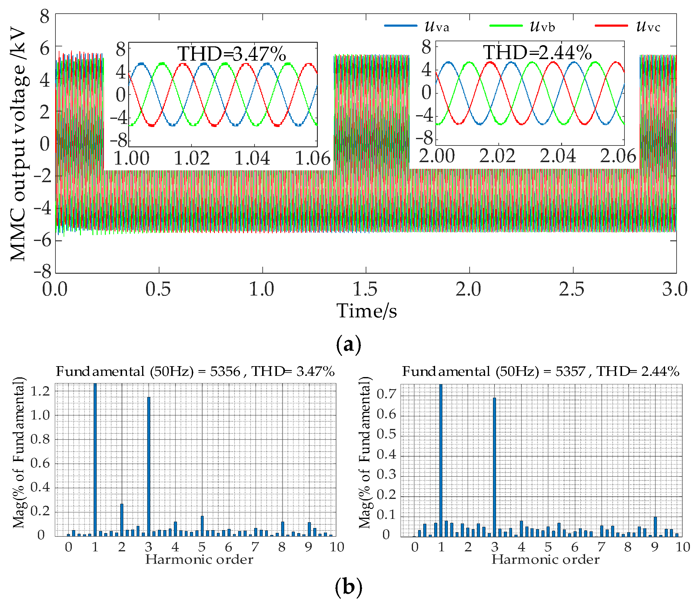
The proposed circulating-current suppression scheme effectively suppresses the circulating current inside the MMC. It optimizes the terminal voltage and current of the MMC, and the total harmonic distortion (THD) of the output voltage and current is reduced from 3.47% and 1.38% to 2.44% and 0.86%, respectively, after activating the circulating-current suppressor. Reducing its harmonic distortion rate also suppresses the power output pulsations and oscillations.
(2)
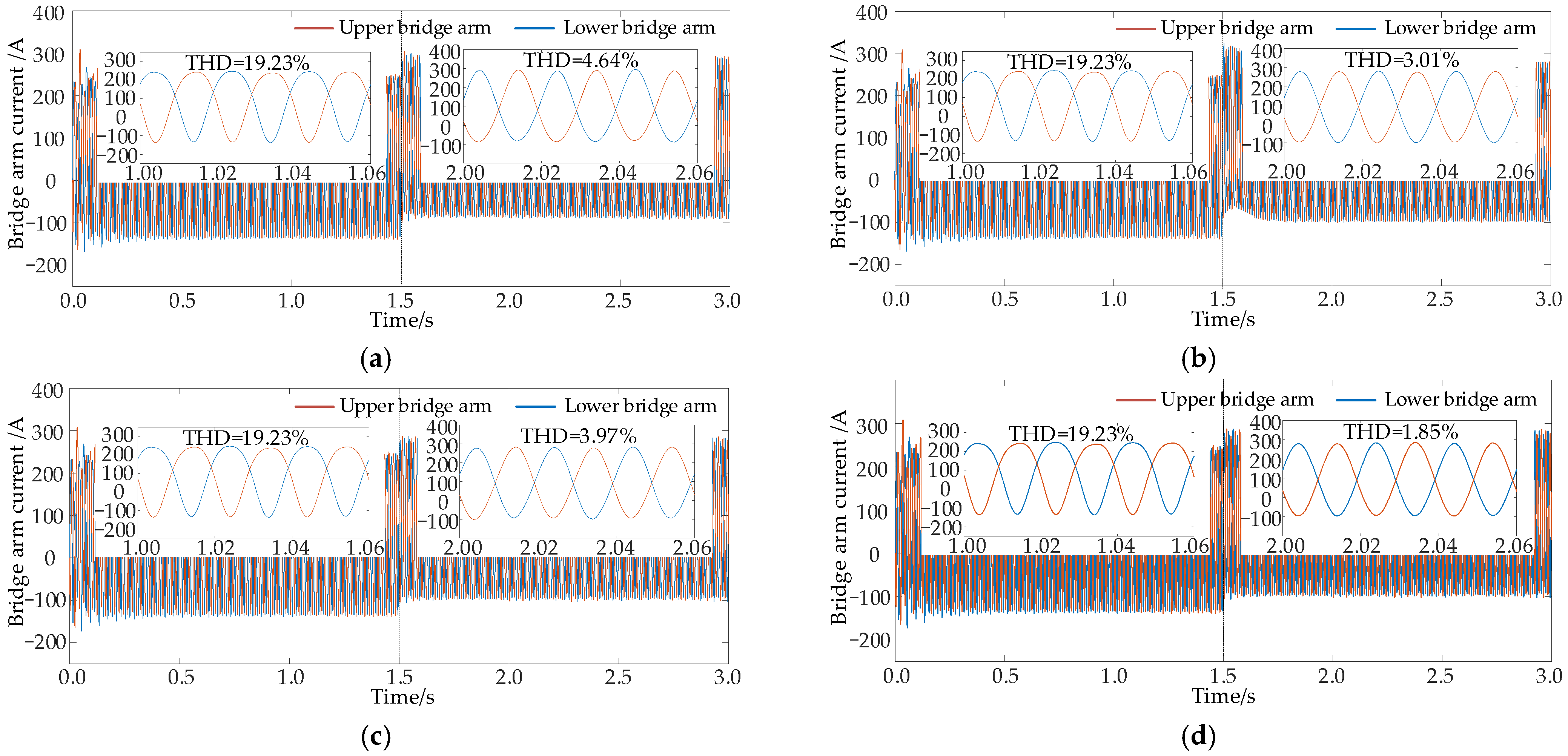
Compared with the traditional PI, PIR, and single passive control, the strategy proposed in this paper is more effective in suppressing the circulating current, and reduces the circulating-current THD to 3.43%, of which the twofold frequency component is reduced to 1.23%. Compared to the case without suppression, the proposed control strategy reduces the circulating-current THD by 44.62% and the twofold frequency component by 37.51%. Meanwhile, the bridge arm current waveform quality is also significantly improved, with its THD reduced from 19.23% to 1.85% after enabling circulating-current suppression, verifying its superiority in suppressing circulating current and enhancing power quality.
(3)
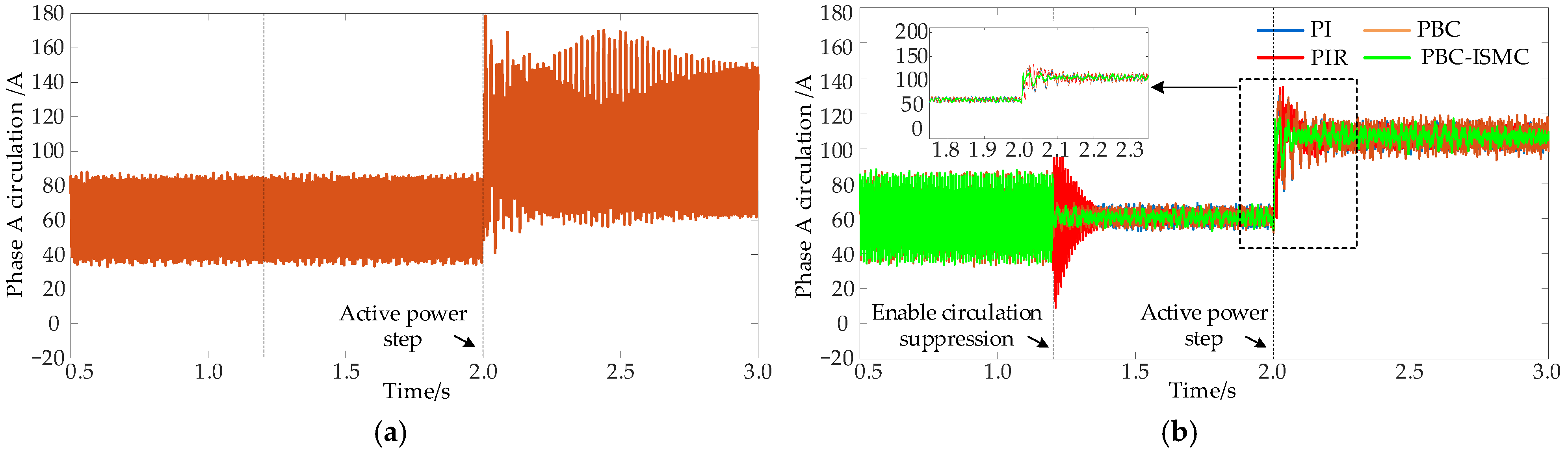
Under dynamic disturbances such as sudden changes in active power, the PBC-ISMC control strategy shows stronger robustness and dynamic adaptability, and the system output is more stable and reliable.

Author Contributions

Conceptualization, W.Z.; methodology, W.Z. and X.Y.; validation, M.Z.; formal analysis, X.Y. and D.Z.; writing—original draft preparation, W.Z.; writing—review and editing, W.Z. and J.L. All authors have read and agreed to the published version of the manuscript.

Funding

This research was partially funded by the National Natural Science Foundation of China (grant no. 62273142), and Hunan Provincial Department of Education Scientific Research Project (grant no. 23B1017).

Data Availability Statement

The data presented in this study are available in the text.

Conflicts of Interest

The authors declare no conflicts of interest.

References

  1. Fan, Q.; Wang, X.; Yuan, J.; Liu, X.; Hu, H.; Lin, P. A review of the development of key technologies for offshore wind power in China. J. Mar. Sci. Eng. 2022, 10, 929. [Google Scholar] [CrossRef]
  2. Liu, S.; Zhang, L.; Lu, J.; Zhang, X.; Wang, K.; Gan, Z.; Liu, X.; Jing, Z.; Cui, X.; Wang, H. Advances in urban wind resource development and wind energy harvesters. Renew. Sustain. Energy Rev. 2025, 207, 114943. [Google Scholar] [CrossRef]
  3. Chen, H.; Zuo, Y.; Chau, K.T.; Zhao, W.; Lee, C.H.T. Modern electric machines and drives for wind power generation: A review of opportunities and challenges. IET Renew. Power Gener. 2021, 15, 1864–1887. [Google Scholar] [CrossRef]
  4. Tiismus, H.; Maask, V.; Astapov, V.; Korõtko, T.; Rosin, A. State-of-the-Art Review of Emerging Trends in Renewable Energy Generation Technologies. IEEE Access 2025, 13, 10820–10843. [Google Scholar] [CrossRef]
  5. Qian, T.; Yao, L. Research on Power Quality Assessment of Wind Power Grid-Connected Systems Based on Game Theory Combination Weighting. Electronics 2025, 14, 1500. [Google Scholar] [CrossRef]
  6. Cavus, M. Advancing Power Systems with Renewable Energy and Intelligent Technologies: A Comprehensive Review on Grid Transformation and Integration. Electronics 2025, 14, 1159. [Google Scholar] [CrossRef]
  7. Catalán, P.; Wang, Y.; Arza, J.; Chen, Z. A comprehensive overview of power converter applied in high-power wind turbine: Key challenges and potential solutions. IEEE Trans. Power Electron. 2023, 38, 6169–6195. [Google Scholar] [CrossRef]
  8. Xue, T.; Lyu, J.; Wang, H.; Cai, X. A complete impedance model of a PMSG-based wind energy conversion system and its effect on the stability analysis of MMC-HVDC connected offshore wind farms. IEEE Trans. Energy Convers. 2021, 36, 3449–3461. [Google Scholar] [CrossRef]
  9. Mussetta, M.; Le, X.C.; Trinh, T.H.; Doan, A.T.; Duong, M.Q.; Tanasiev, G.N. An Overview of the Multilevel Control Scheme Utilized by Microgrids. Energies 2024, 17, 3947. [Google Scholar] [CrossRef]
  10. Peng, X.; Liu, Z.; Jiang, D. A review of multiphase energy conversion in wind power generation. Renew. Sustain. Energy Rev. 2021, 147, 111172. [Google Scholar] [CrossRef]
  11. Zhao, T.; Wu, S.; Cui, S. Multiphase PMSM with asymmetric windings for more electric aircraft. IEEE Trans. Transp. Electrif. 2020, 6, 1592–1602. [Google Scholar] [CrossRef]
  12. Rao, Z.; Zhang, Z.; Huang, S.; Long, Z.; Wu, G. Characteristics and current harmonic control of N* three-phase PMSG for HVDC transmission Based on MMC. Energies 2020, 13, 178. [Google Scholar] [CrossRef]
  13. Diab, A.A.Z.; Ebraheem, T.; Aljendy, R.; Sultan, H.M.; Ali, Z.M. Optimal design and control of MMC STATCOM for improving power quality indicators. Appl. Sci. 2020, 10, 2490. [Google Scholar] [CrossRef]
  14. Kok, C.L.; Tang, H.; Teo, T.H.; Koh, Y.Y. A DC-DC Converter with Switched-Capacitor Delay Deadtime Controller and Enhanced Unbalanced-Input Pair Zero-Current Detector to Boost Power Efficiency. Electronics 2024, 13, 1237. [Google Scholar] [CrossRef]
  15. Zhao, J.; Gao, C.; Cao, K.; Yang, X.; Mao, W.; Jiang, J. Research on high-voltage large-capacity modular multilevel converter (MMC) system. In Proceedings of the 2012 Second International Conference on Intelligent System Design and Engineering Application, Sanya, China, 6–7 January 2012; IEEE: New York, NY, USA, 2012; pp. 1470–1474. [Google Scholar]
  16. Gomis-Bellmunt, O.; Sau-Bassols, J.; Prieto-Araujo, E.; Cheah-Mane, M. Flexible converters for meshed HVDC grids: From flexible AC transmission systems (FACTS) to flexible DC grids. IEEE Trans. Power Deliv. 2019, 35, 2–15. [Google Scholar] [CrossRef]
  17. Zhang, Y.; Li, S.; Zhang, X.; Liu, C.; Liu, Z.; Luo, B. A Hybrid Low Capacitance Modular Multilevel Converter for Medium Voltage PMSM Drive and Its Control Method. IEEE Access 2023, 11, 92796–92806. [Google Scholar] [CrossRef]
  18. Zhang, Q.N.; Zhang, Z.R.; Jin, Y.Q.; Xu, Z. DC transmission system suitable for ultra-large-scale offshore wind power grid-connected system. Electr. Power Autom. Equip. 2025, 45, 106–114. (In Chinese) [Google Scholar]
  19. Zuo, T.; Zhang, Y.; Xie, X.; Meng, K.; Tong, Z.; Dong, Z.Y.; Jia, Y. A review of optimization technologies for large-scale wind farm planning with practical and prospective concerns. IEEE Trans. Ind. Inform. 2022, 19, 7862–7875. [Google Scholar] [CrossRef]
  20. Mastoi, M.S.; Zhuang, S.; Haris, M.; Hassan, M.; Ali, A. Large-scale wind power grid integration challenges and their solution: A detailed review. Environ. Sci. Pollut. Res. 2023, 30, 103424–103462. [Google Scholar] [CrossRef]
  21. Wickramasinghe, H.R.; Konstantinou, G.; Pou, J.; Agelidis, V.G. Interactions between indirect DC-voltage estimation and circulating current controllers of MMC-based HVDC transmission systems. IEEE Trans. Power Syst. 2017, 33, 829–838. [Google Scholar] [CrossRef]
  22. Hui, L.; Peng, Z.; Sijia, L. Transient analysis of MMC circulating current suppression strategy. Power Syst. Prot. Control. 2021, 49, 30–38. (In Chinese) [Google Scholar]
  23. Reddy, G.A.; Shukla, A. Circulating current optimization control of MMC. IEEE Trans. Ind. Electron. 2020, 68, 2798–2811. [Google Scholar] [CrossRef]
  24. Tu, Q.; Xu, Z.; Guan, M.; Zheng, X.; Zhang, J. Design of circulating current suppressing controllers for modular multi-level converter. Autom. Electr. Power Syst. 2010, 34, 57–61. (In Chinese) [Google Scholar]
  25. Tu, Q.; Xu, Z.; Xu, L. Reduced switching-frequency modulation and circulating current suppression for modular multilevel converters. IEEE Trans. Power Deliv. 2011, 26, 2009–2017. [Google Scholar]
  26. Yang, X.F.; Zheng, Q.L. A novel universal circulating current suppressing strategy based on the MMC circulating current model. Proc. CSEE 2012, 32, 59–65. (In Chinese) [Google Scholar]
  27. Ban, M.F.; Shen, K.; Wang, J.Z. A Novel Circulating Current Suppressor for Modular Multilevel Converters Based on Quasi-proportional-resonant Control. Autom. Electr. Power Syst. 2014, 38, 85–89. (In Chinese) [Google Scholar]
  28. Yuan, B.; Xu, J.; Zhao, C.; He, Z.P.; Pang, H.; Ma, W. Optimal design of pr circulating current suppressing controllers for modular multilevel converters. Proc. CSEE 2015, 35, 2567–2575. (In Chinese) [Google Scholar]
  29. Yan, F.Y.; Tang, G.F.; He, Z.Y. A novel circulating current controller for modular multilevel converter. Proc. CSEE 2014, 38, 104–109. (In Chinese) [Google Scholar]
  30. He, L.; Zhang, K.; Xiong, J.; Fan, S. A repetitive control scheme for harmonic suppression of circulating current in modular multilevel converters. IEEE Trans. Power Electron. 2014, 30, 471–481. [Google Scholar] [CrossRef]
  31. Konstantinou, G.; Pou, J.; Ceballos, S.; Picas, R.; Zaragoza, J.; Agelidis, V.G. Control of circulating currents in modular multilevel converters through redundant voltage levels. IEEE Trans. Power Electron. 2015, 31, 7761–7769. [Google Scholar] [CrossRef]
  32. Chen, X.; Liu, J.; Song, S.; Ouyang, S. Circulating harmonic currents suppression of level-increased NLM based modular multilevel converter with deadbeat control. IEEE Trans. Power Electron. 2020, 35, 11418–11429. [Google Scholar] [CrossRef]
  33. Ma, K.; Li, E.; He, B.; Cai, X. Mechanism and cancellation of DC current fluctuation in MMC excited by circulating current mitigation under nearest level control. IEEE J. Emerg. Sel. Top. Power Electron. 2022, 10, 6822–6831. [Google Scholar] [CrossRef]
  34. Reddy, G.A.; Shukla, A. Arm-current-sensorless circulating current control of MMC. IEEE Trans. Ind. Appl. 2021, 58, 444–456. [Google Scholar] [CrossRef]
  35. Yang, X.; Li, Z.; Zheng, T.Q.; You, X.; Kobrle, P. Virtual impedance sliding mode control-based MMC circulating current suppressing strategy. IEEE Access 2019, 7, 26229–26240. [Google Scholar] [CrossRef]
  36. Priya, M.; Ponnambalam, P. Circulating current control of phase-shifted carrier-based modular multilevel converter fed by fuel cell employing fuzzy logic control technique. Energies 2022, 15, 6008. [Google Scholar] [CrossRef]
  37. Bergna-Diaz, G.; Zonetti, D.; Sanchez, S.; Ortega, R.; Tedeschi, E. PI passivity-based control and performance analysis of MMC multiterminal HVDC systems. IEEE J. Emerg. Sel. Top. Power Electron. 2018, 7, 2453–2466. [Google Scholar] [CrossRef]
  38. Wang, X.G.; Wang, H.L.; Xue, X.; Li, X.Y. Grid-connected current control for MMC-MG adopting nonlinear passive theory. J. Control. Theory Appl. 2022, 39, 1541–1550. (In Chinese) [Google Scholar]
  39. Aghahadi, M.; Piegari, L.; Lekić, A.; Shetgaonkar, A. Sliding mode control of the mmc-based power system. In Proceedings of the IECON 2022—48th Annual Conference of the IEEE Industrial Electronics Society, Brussels, Belgium, 17–20 October 2022; IEEE: New York, NY, USA, 2022; pp. 1–6. [Google Scholar]
  40. Komurcugil, H.; Biricik, S.; Bayhan, S.; Zhang, Z. Sliding mode control: Overview of its applications in power converters. IEEE Ind. Electron. Mag. 2020, 15, 40–49. [Google Scholar] [CrossRef]
Figure 1. MMC-based multiphase wind power generation system.
Electronics 14 02722 g001
Figure 2. Grid-connected MMC three-phase topology.
Electronics 14 02722 g002
Figure 3. Dual-frequency AC component extraction method.
Electronics 14 02722 g003
Figure 4. Bode diagram of transfer function for different values of kg.
Electronics 14 02722 g004
Figure 5. Mathematical model of MMC circulation.
Electronics 14 02722 g005
Figure 6. Block diagram of MMC loop current passive decoupling control.
Electronics 14 02722 g006
Figure 7. Comparison of saturation function and hyperbolic tangent function images.
Electronics 14 02722 g007
Figure 8. Block diagram of the passive-integral sliding mode circulating current rejection controller. (a) Circulation extraction and controlled volume generation. (b) Circulation suppression controller.
Electronics 14 02722 g008
Figure 9. Overall control block diagram of MMC grid-connected system.
Electronics 14 02722 g009
Figure 10. MMC output voltage waveforms before and after PBC-ISMC loop current suppression. (a) Output voltage waveform. (b) FFT spectral analysis of voltage waveforms.
Electronics 14 02722 g010
Figure 11. MMC output current waveforms before and after PBC-ISMC loop current suppression. (a) Output current waveform. (b) FFT spectral analysis of current waveforms.
Electronics 14 02722 g011
Figure 12. MMC output power waveforms before and after PBC-ISMC loop current suppression.
Electronics 14 02722 g012
Figure 13. MMC three-phase ring current with different ring current suppression methods. (a) PI control. (b) PIR control. (c) PBC control. (d) PBC-ISMC control.
Electronics 14 02722 g013
Figure 14. A-phase bridge arm current of MMC with different circulating current suppression methods. (a) PI control. (b) PIR control. (c) PBC control. (d) PBC-ISMC control.
Electronics 14 02722 g014
Figure 15. MMC circulating current suppression effect at active power command step. (a) Phase A circulation without circulation suppression. (b) Phase A circulation under different circulation suppression modes.
Electronics 14 02722 g015
Table 1. Main parameters of the MMC grid-connected system.
ParametersValueParametersValue
Grid-connected active power3 MWSubmodule capacitance4.7 mF
DC voltage11 kVBridge arm resistance0.002 mΩ
Effective value of AC side line voltage6.6 kVBridge arm inductance15 mH
The number of bridge arm submodules22Rated grid frequency50 Hz
Table 2. Main control parameters in the simulation.
Control MethodParameter
PIKp = 58.5, Ki = 8.5
PIRKp = 12.4, Ki = 0.18, Kr = 32
PBCRa1 = Ra2 = 35
PBC-ISMCRa1 = Ra2 = 200, kp1 = kp2 = 2.8, ki1 = ki2 = 0.078, λ1 = λ2 = 9000, k1 = k2 = 480
Table 3. FFT analysis of the A-phase circulation.
Suppression MethodProportion of Total Harmonics in CirculationProportion of Double Frequency ComponentsDc Component in Circulation
Circulation-free suppression48.05%38.74%91.63 A
PI8.17%7.14%91.29 A
PIR5.40%4.75%90.95 A
PBC8.16%6.79%91.18 A
PBC-ISMC3.43%1.23%90.91 A
Disclaimer/Publisher’s Note: The statements, opinions and data contained in all publications are solely those of the individual author(s) and contributor(s) and not of MDPI and/or the editor(s). MDPI and/or the editor(s) disclaim responsibility for any injury to people or property resulting from any ideas, methods, instructions or products referred to in the content.

