Article

Resonance Circuit Design Eliminating RX-Side Series Capacitor in LCC-LCC WPT Systems Using an RX Shield Coil

1
Automotive Engineering, Department of Smart Mobility Engineering, Keimyung University, Daegu 42601, Republic of Korea
2
Cho Chun Shik Graduate School of Mobility, Korea Advanced Institute of Science and Technology, Daejeon 34051, Republic of Korea
*
Author to whom correspondence should be addressed.
Electronics 2025, 14(13), 2686; https://doi.org/10.3390/electronics14132686
Submission received: 23 May 2025 / Revised: 28 June 2025 / Accepted: 1 July 2025 / Published: 2 July 2025
(This article belongs to the Special Issue Wireless Power Transfer Systems and Applications)

Abstract

This paper presents a new resonance circuit design method for LCC-LCC wireless power transfer (WPT) systems that incorporate reactive shielding (SH) coils on the receiver (RX) side to suppress the electromagnetic field (EMF). While reactive SH coils are known to reduce leakage magnetic fields, they alter the equivalent inductance of the system, thereby disrupting resonance conditions. To address this, we derive the changes in the equivalent inductance caused by SH coils and propose a method to re-select the series capacitor on both the RX and TX sides. Furthermore, we investigate the adjustment of the required input voltage to maintain output power with the SH coils. The proposed methodology eliminates the need for a series capacitor on the RX side, simplifies the network, and reduces the magnetic leakage field by up to 55.6%, as verified by the simulation and measurement results. This study provides a new pathway toward compact, EMF-conscious and LCC-based WPT systems.

1. Introduction

Wireless power transfer (WPT) systems are increasingly being adopted across a wide range of applications, including consumer electronics, biomedical implants, industrial automation, and electric vehicles [1,2,3,4,5,6]. By eliminating the need for direct electrical contact, WPT systems enhance safety and usability in environments where cables may be cumbersome or vulnerable to wear.
However, as WPT systems are deployed in higher power applications, such as electric vehicles (EVs), concerns about human exposure to electromagnetic fields (EMFs) have become more critical [7]. The leakage of magnetic field from the transmitting (TX) or receiving (RX) coil can result in elevated EMF levels around the system, potentially raising safety concerns related to long-term exposure. To ensure human safety, regulatory bodies such as the International Commission on Non-Ionizing Radiation Protection (ICNIRP) have defined strict EMF limits [8,9].
To meet these standards, various shielding techniques have been proposed, including the use of reactive shield (SH) coils, which create opposing magnetic fields to cancel out leakage flux [10,11,12]. While effective in EMF suppression, the use of SH coils inevitably alters the magnetic coupling and resonant behavior of the system. These effects must be carefully considered to avoid impairing the overall system performance.
Among the diverse resonance topologies used in WPT systems—such as series–series (SS), parallel–parallel (PP), and hybrid configurations—the LCC-LCC topology is gaining significant attention, particularly in high-power EV charging scenarios. This topology is favorable due to its current-source characteristics at the TX side, making it suitable for constant current (CC) battery charging regardless of load variations. The LCC-LCC system can maintain a nearly constant current through the TX coil, thereby regulating the induced voltage at the RX side to facilitate efficient and stable charging in the CC mode.
This paper focuses on a generalized LCC-LCC WPT system that incorporates a reactive SH coil, not only for electric vehicle charging but also for potential applications across other domains. While the SH coil contributes to EMF reduction, it also impacts system parameters in ways that must be analytically understood and properly compensated for in the resonance design.
The proposed approach is distinct from conventional constant charging control strategies—such as mutual-inductance dynamic predicted control [13], self-oscillating charging schemes [14], and communication-free load identification methods [15]—which typically focus on control algorithms. In contrast, this work emphasizes circuit-level optimization under SH-induced inductance variation to eliminate the secondary series capacitor.
However, most prior studies using reactive SH coils have not considered the reduction in equivalent inductance caused by the opposing magnetic field generated by the SH coil. This paper not only addresses this effect through analytical modeling but also proposes a method to eliminate the RX-side series capacitor by appropriately selecting the resonance frequency of the SH coil.
In summary, the key contributions of this work are summarized as follows:
  • The analytical modeling of the equivalent inductance variation in the main coil caused by the shielding coil: The introduction of a reactive shielding (SH) coil near the receiving (RX) coil changes the magnetic field distribution, which in turn reduces the equivalent inductance of the RX-side resonant loop. This paper derives analytical expressions that describe how the SH coil parameters affect the RX coil’s inductance. This modeling provides essential insights for accurately designing the resonant circuit in shield-integrated WPT systems.
  • Resonant component redesign methodology: Using the derived expressions, we propose a capacitor selection method that eliminates the need for a series capacitor on the RX side and ensures zero-voltage switching (ZVS) or zero-phase-angle (ZPA) operation on the inverter of the TX side. This approach simplifies the circuit structure and improves the robustness of the design under EMF constraints.
  • The analytical modeling of input voltage adjustment for output power regulation with a SH coil on the RX side: The reduced coupling caused by SH coil insertion lowers the induced voltage on the RX coil, necessitating an increase in the TX input voltage to maintain constant output power. We present an analytical formulation to predict this voltage shift, aiding system-level power regulation design.
By integrating EMF mitigation with resonant circuit design, the proposed approach bridges the gap between electromagnetic compliance and efficient WPT. This integration not only ensures adherence to electromagnetic field exposure guidelines but also enables the elimination of bulky components, such as the RX-side series capacitor, resulting in a more compact and streamlined receiver-side resonant circuit. Furthermore, by reducing the number of passive components, the proposed method can lead to cost savings and improved system manufacturability, making it advantageous for practical implementation in size- and cost-constrained applications.
This advantage makes the approach particularly suitable for biomedical and industrial applications, where receiver module miniaturization and cost reduction are critical. In these cases, the use of SH coils on the RX side may also be considered, and our method helps lower the overall cost and size of the receiver unit by simplifying the resonance circuit.
The remainder of this paper is structured as follows: Section 2 discusses the changes in the equivalent inductance, the method for eliminating the resonance of the resonance capacitor, the design of the TX resonance capacitor considering zero-voltage switching (ZVS), and the input voltage design. Section 3 validates the proposed resonance circuit design through simulations and experiments. Section 4 summarizes the findings and significance of the paper.

2. Design of LCC-LCC WPT Systems with a Shielding Coil in the Receiver Side

This section discusses the LCC-LCC system design with an SH coil on the RX side. This design addresses the changes in the equivalent inductance of the RX coil when an SH coil is used. We also discuss a method for selecting the resonance frequency of the SH coil to eliminate the need for series capacitors in the RX, a design of series capacitors in the TX to satisfy the ZVS condition for the stable operation of the power circuit, and an approach for designing the input voltage when the SH coil is applied.

2.1. Analysis of RX Inductance Variation and Design of the SH Coil Resonance Frequency and Input Voltage

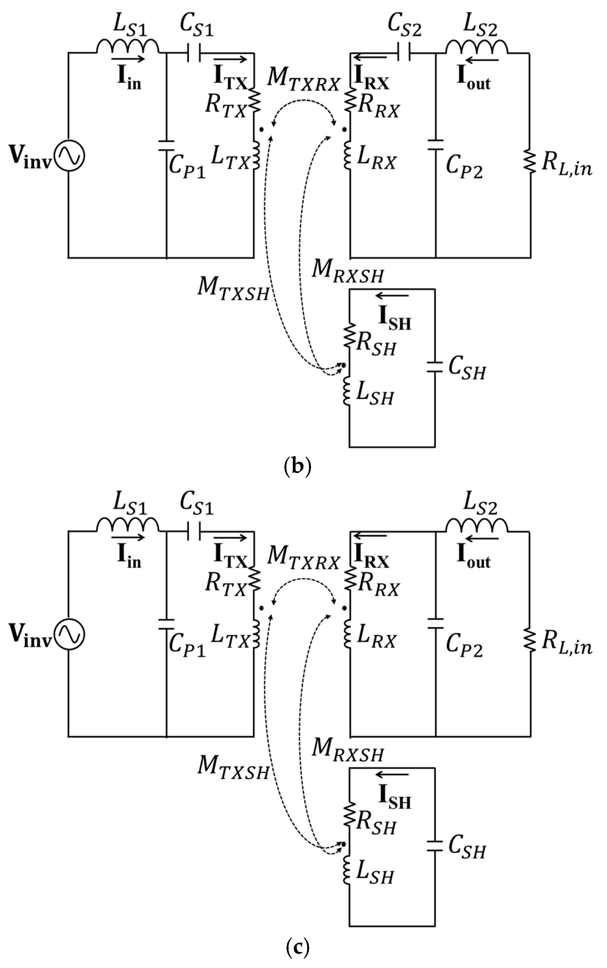
Figure 1 shows the application of a SH coil on the RX side of a WPT system. Figure 1a shows the conceptual configuration of the SH coil applied to the RX. Inductance is defined as the magnetic flux per unit current flowing through the coil. When an SH coil is applied, current flows in the opposite direction to the RX coil to reduce the leakage of magnetic fields. Thus, the total magnetic flux linked to the RX coil decreases, thereby reducing its equivalent RX coil inductance. Figure 1b shows the corresponding equivalent circuit diagram. In a conventional LCC-LCC system, the capacitance can be expressed as Equation (1) [16].
C P 1 = 1 ω o 2 L S 1 , C S 1 = 1 ω o 2 L T X L S 1 , C P 2 = 1 ω o 2 L S 2 , C S 2 = 1 ω o 2 ( L R X L S 2 )
As aforementioned, previous studies on reactive SH focused on reducing the leakage of magnetic fields without analyzing the characteristics of resonant circuits when SH coils are applied [10,11,12].
To derive the decrease in the equivalent inductance of the RX, the KVL equations related to I R X , I O U T , and I S H in Figure 1b are given by Equations (2a)–(2c), and the reactance X S H is defined in Equation (3).
0 = j ω o M T X R X I T X + j ω o L R X + 1 j ω o C P 2 + 1 j ω o C S 2 I R X 1 j ω o C P 2 I o u t + j ω o M R X S H I S H
0 = 1 j ω o C P 2 I R X + j ω o L S 2 + 1 j ω o C P 2 + R L , i n I o u t
0 = j ω o M T X S H I T X + j ω o M R X S H I R X + j X S H I S H
X S H = ω o L S H 1 ω o C S H
If Equation (2b) satisfies Equation (1), I o u t can be expressed as Equation (4).
I o u t = 1 j ω o C P 2 R L , i n I R X
Furthermore, by rearranging Equation (2c) with respect to I S H , Equation (5) can be obtained.
I S H = ω o M T X S H I T X ω o M R X S H I R X   X S H
Finally, by substituting Equations (4) and (5) into (2a), we obtain Equation (6).
0 = j ( ω o M T X R X ω o 2 M T X S H M R X S H X S H ) I T X + j ω o ( L R X L S 2 ω o ( M R X S H ) 2 X S H ) + 1 j ω o C S 2 + 1 ω o 2 C P 2 2 R L , i n I R X
By expressing the system as shown in Equation (6), it becomes possible to physically interpret each term related to the TX and RX coils. First, the negative term within the I T X expression indicates a reduction in the voltage induced in the RX coil due to the SH coil. In addition, the term multiplied by I R X , specifically the component following j ω o , reflects the reduction in the inductance of the RX coil.
The imaginary part of the term in parentheses preceding I R X in Equation (6) can be expressed as Equation (7).
j ω o L R X ω o M R X S H 2 X S H   L S 2 + 1 j ω o C S 2
In Equation (7), the equivalent inductance of the RX coil is expressed as Equation (8). Equation (8) indicates that the equivalent inductance of the RX coil decreases due to the opposing magnetic field generated by the SH coil.
L R X , E q = L R X ω o M R X S H 2 X S H
As expressed in Equation (8), the decrease in the equivalent inductance of the RX coil by the SH coil is determined by X S H ,   X R X S H , and ω o .
Here, C S 2 offsets the + reactance caused by the preceding inductance with -reactance. In Equation (7), the value of X S H that makes the +reactance term zero is given by Equation (9), and in this case, C S 2 becomes unnecessary.
X S H = ω o ( M R X S H ) 2 L R X L S 2
Based on Equations (3) and (9), C S H can be rearranged as Equation (10). By designing C S H based on the value derived in Equation (10), it can be reconfirmed that the RX-side capacitor C S 2 can be eliminated.
C S H = 1 ω o 2 ( L S H 1 ( M R X S H ) 2 L R X L S 2   )
Finally, the resonance frequency of the SH coil can be expressed as Equation (11).
ω S H = 1 L S H C S H = ω o 1 ( M R X S H ) 2 L S H ( L R X L S 2 )
It is important to note that Equations (10) and (11) are unaffected by coil misalignment between the TX and RX coils. This is because these equations do not include mutual inductance terms such as M T X R X or M T X S H . Therefore, once C S H is designed using the proposed method, the RX-side capacitor C S 2 can be eliminated regardless of misalignment. This indicates that the proposed system exhibits structural robustness against coil misalignment.
Figure 2 shows the modified LCC-LCC topology when the resonance frequency of the SH coil is selected based on Equation (11). As shown in Figure 2, C S 2 is eliminated from the RX-side resonant circuit, resulting in a short circuit. Using the proposed method, an efficient RX-side resonance circuit can be designed when an SH coil is used to reduce the leakage of magnetic fields.
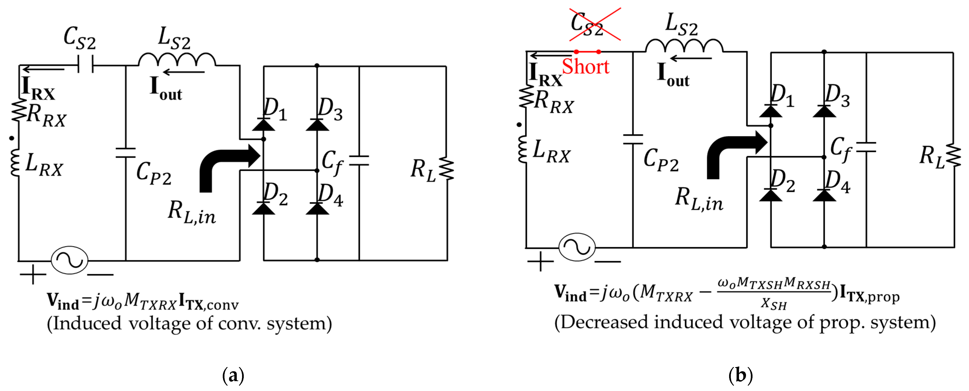
Furthermore, the addition of an SH coil alters the induced voltage in the RX coil. Despite this change, the same amount of power must be delivered to the load. Figure 3 shows the circuit on the RX side, considering the voltage induced by the TX and SH coils. Figure 3a shows a conventional WPT system. Applying KVL to the I R X loop, we obtain Equation (12).
0 = (   j ω o L T X + 1 ω o C P 1 + 1 ω o C S 2 ) I R X 1 j ω o C P 2 I o u t
By rearranging Equation (12) with respect to I o u t , we obtain Equation (13).
I o u t , c o n v = ω o 2 M T X R X C P 2 I T X , c o n v
In Equation (13), the root mean square (RMS) value of the TX current can be expressed as Equation (14) [11].
I T X , c o n v , R M S = ω o C P 1 4 π 2 V D C , c o n v
By substituting Equation (14) into Equation (13), we obtain Equation (15).
I o u t , c o n v , R M S = ω o 3 M T X R X C P 1 C P 2 4 π 2 V D C , c o n v
Figure 3b shows the proposed system. By eliminating the reactance component in the parentheses preceding I R X in Equation (6) and using Equation (4), the I O U T of the proposed system can be expressed as Equation (16).
I o u t , p r o p , R M S = ω o 3 ( M T X R X ω o M T X S H M R X S H X S H ) C P 1 C P 2 4 π 2 V D C , p r o p
The output current of the conventional system Equation (15) and the proposed system Equation (16) must be equal. The input voltage of the proposed system can be expressed as Equation (17).
V D C , p r o p = M T X R X M T X R X ω o M T X S H M R X S H X S H V D C , c o n v
In the conventional LCC-LCC system, the output current I o u t can be expressed as shown in Equation (18) [16].
I o u t = j C P 1 C P 2 M ω o 3 V i n v , ω o
where V i n v , ω o is the fundamental component of the inverter output.
The relationship between the output power and load resistance can be represented by Equation (19).
P o u t | I o u t | 2 R L
Depending on the load resistance R L , the output current I o u t may increase or decrease to maintain the rated output power. According to Equation (18), the input voltage also increases or decreases in the same direction. Consequently, V D C , c o n v in Equation (17) changes with R L , whereas V D C , p r o p is determined by factors such as the mutual inductance, operating frequency, and the reactance of the shielding coil. Once the system is fixed, the ratio between V D C , c o n v and V D C , p r o p becomes constant.
This section analyzes the changes in the equivalent inductance of the RX coil when an SH coil is used. In addition, it proposes a method for selecting the resonance frequency of the SH coil to eliminate the series capacitor C S 2 in the RX circuit. Finally, it addresses the changes in the voltage induced by the SH coil and discusses the design method for the input voltage required to ensure that the proposed system delivers the same power to the load as the conventional system.

2.2. Selection of the Series Capacitor of the TX Side for Stable Inverter Operation

This section discusses the method for selecting the series capacitor C S 1 on the TX side of a WPT system to ensure stable inverter operation. In the WPT system, AC can be generated using an inverter. As shown in Figure 1b, the inverter is connected to the TX resonant circuit. Depending on the resonant circuit parameters, the impedance from the inverter output can be inductive, resistive, or capacitive.
For the stable operation of the inverter in the WPT system, the impedance at the inverter output must be inductive [17,18,19,20]. This condition allows the switching elements of the inverter to achieve ZVS.
Before determining the ZVS condition, the zero-phase-angle (ZPA) condition must be defined. The ZPA condition refers to a state in which the impedance from the inverter output is purely resistive, causing the inverter’s output voltage and current to be in phase.
The impedance at the inverter output is denoted as Z i n and is derived in this section.
In resonant systems, the first harmonic approximation (FHA) method can be used. Using this approach, Equation (14) can be rewritten as Equation (20).
I T X = j ω o C P 1 V i n v , ω o
where V i n v , ω o is the fundamental component of the inverter output.
The KVL equation for I T X in Figure 2 is given by Equation (21).
0 = 1 j ω o C P 1 I i n + ( j ω o L T X + 1 j ω o C P 1 + 1 j ω o C S 1 ) I T X + j ω o M T X R X I R X + j ω o M T X S H I S H
When the reactance term in parentheses in Equation (6) for I R X is absent, I R X can be expressed as Equation (22).
I R X = j ω o 3 C P 2 2 R L , i n α I T X
where
α = ω o M T X S H M R X S H X S H M T X R X
By substituting Equations (5), (20) and (22) into Equation (21), and considering Equation (9), Z i n can be expressed as Equation (24).
Z i n = V i n v , ω o I i n = 1 ω o 2 C P 1 2 1 ( β + j ω o L T X L S 1 L R X L S 2 ( M T X S H M R X S H ) 2 1 ω o C s 1 )
where
β = ω o 4 C P 2 2 R L , i n α ( ( L R X L S 2 ) M T X S H M R X S H M T X R X )
The value of C S 1 that nullifies the imaginary part of Equation (24), thereby satisfying the ZPA condition, can be expressed as Equation (26).
C s 1 , Z P A = 1 ω o 2 ( L T X L S 1 L R X L S 2 ( M T X S H M R X S H ) 2 )
To satisfy the ZVS condition, V i n v , ω o must lead I i n , requiring the imaginary part of Z i n to be positive and condition Equation (27) to be met.
C S 1 , Z V S < C S 1 , Z P A
To summarize the design method for ensuring the ZVS of the inverter, the ZPA value, at which the voltage and current in Z i n are in phase, should first be determined using Equation (26). Subsequently, the condition in which the voltage leads the current, as described in Equation (27), must be satisfied.
Table 1 presents a comparison between previous studies and the proposed work. Although both the existing reactive shielding methods ([10,11,12]) and this study achieve EMF reduction, the prior works did not consider the variation in effective inductance caused by the SH coil, nor did they provide a quantitative design for the input voltage. In contrast, this study addresses both aspects. Furthermore, while previous methods were unable to eliminate the RX-side series capacitor, the proposed method successfully removes it. Whereas prior approaches adopted SS topology, the proposed design employs an LCC-LCC topology, which is expected to offer higher applicability in future electric vehicles and high-power AGV systems.

3. Validation of the Proposed Method

This section validates the proposed method through simulations and experiments. We considered three cases: 1. without applying an SH coil (w/o SH); 2. with an SH coil applied but without modifying the resonant capacitor in the RX resonant circuit and tuning the series capacitor in the TX resonant circuit representing the conventional reactive SH method (w/SH, conv.); 3. adjusting the resonance frequency of the SH coil, eliminating the series resonant capacitor in the RX resonant circuit, and tuning the series capacitor in the TX resonant circuit to ensure ZVS (w/SH, prop.). For each case, the efficiency, electromagnetic field (EMF), and waveforms of V i n v and I i n were evaluated.

3.1. Simulation

Figure 4 shows the proposed coil model. The diameter of both TX and RX coils is 150 mm, and that of the SH coil is 260 mm (Figure 4a). The TX and RX coils have 12 turns, whereas the SH coil has 6 turns. The air gap between the TX and RX coils was set to 50 mm. ANSYS MAXWELL 2025 was used to extract the inductance values. Table 2 lists the inductance and mutual inductance of the simulation model. Figure 4b shows the simulation setup for extracting the EMF. In all three cases, the EMF was extracted at a point 100 mm away from the end of the SH coil. Notably, case 1 represents the model without a SH coil; however, for a fair comparison, the measurements were taken at the same location as in cases 2 and 3. In addition, in case 1, the SH coil current was set to 0 A. Figure 5 shows the circuit models used in the circuit simulation, and Table 3 lists their parameters. Figure 5a shows the results for case 1, and Figure 5b shows those for case 2. Figure 5c shows the circuit model incorporating the proposed method. In this case, the RX-side series capacitor C S 2 is not required, and the TX-side series capacitor C S 1 is tuned to satisfy the ZVS condition.
The input voltage for the proposed method was calculated using Equation (17). By comparing the input voltages in cases 2 and 3, we found that the proposed method could transfer the same output power of 50 W even with an input voltage that is 10 V lower than that of the conventional method (Table 3).
These results demonstrate that the power transfer capacity of the proposed system is higher than that of the conventional method.
Figure 6 compares the efficiency and EMF for the three cases. The efficiency of the conventional resonance design with an SH coil was 8.4% lower than that of the system without an SH coil (Figure 6a), whereas the efficiency of the proposed resonance design with an SH coil decreased by 7%. These results show that, in addition to eliminating the RX-side series capacitor C S 2 , the proposed design outperforms the conventional design with an SH coil. Figure 6b shows the EMFs of the conventional and proposed methods with and without an SH coil. The proposed method exhibited the lowest EMF. Compared with the conventional method without an SH coil, the proposed method reduced the magnetic field by 36.7–55.6% (Figure 6b). Figure 7 shows the waveforms of the inverter output voltage ( V i n v ) and current ( I i n ).
The conventional resonance circuit design with an SH coil exhibited a phase difference of 31.2° between the zero crossings of the V i n v and I i n (Figure 7a), which is higher than that recorded by the proposed resonance circuit design with an SH coil (21.9°) (Figure 7b). These results demonstrate that the proposed method improves the ZVS condition.

3.2. Experiment

This section further validates the proposed method through experiments. Experiments were conducted for the three cases considered in the simulations. Herein, we determined and compared the efficiency and EMF of the three cases. In addition, the V i n v and I i n waveforms were analyzed for cases with an SH coil to determine the effect of the employed method on the ZVS condition.
Figure 8 shows the experimental setup. The efficiency was measured as the ratio of the input power from the DC power supply to the output power at the electronic load. For the WPT experiment, power electronics circuits, including inverters and rectifiers, were used. Along with the TX, RX, and RXSH coils, various waveforms were observed using an oscilloscope, and an EMF probe was used to measure the magnetic field. Figure 8b shows the setup for the EMF measurements. The EMF was measured at points 100–300 mm from the end of the RXSH coil at intervals of 50 mm. Table 4 presents the values of the circuit components and other parameters used in the experiments. Case 1 corresponds to the reference configuration without any SH coil. Case 2 applies a conventional reactive SH coil method. Case 3 represents the proposed approach, which applies a reactive SH coil while considering the reduction in equivalent inductance and tuning the resonance frequency of the SH coil to eliminate the need for the secondary series capacitor C S 2 . The operating frequency was set to 85 kHz, and a 50 W power transfer was performed. The input voltage for the proposed method was calculated using Equation (17). The RX-side series capacitor C S 2 was not used in the proposed method, and C S 1 was tuned based on Equation (26) to improve the ZVS condition.
Figure 9 shows the power transfer efficiency and EMF of the systems. The conventional resonance circuit design with an SH coil exhibited a power transfer efficiency 6.1% lower than that of the system without an SH coil (Figure 9a). In contrast, the efficiency of the proposed design was 4.7% lower than that of the system without an SH coil. These results imply several important insights. First, compared to the conventional reactive shielding method, the proposed method considers the reduction in equivalent inductance caused by the SH coil and accordingly tunes the resonance condition more precisely. Since power transfer efficiency is highly sensitive to accurate resonance, the proposed design, even without the RX-side capacitor C S 2 , achieves 1.4% higher efficiency than the conventional approach. Additionally, Case 3 operates with a lower input voltage than Case 2, resulting in reduced current through the TX coil. This lower current leads to weaker radiated magnetic fields, thereby improving the EMF performance as well. Since the TX coil current is further reduced in the proposed method, the thermal stress on the TX side is expected to be lower than that of the conventional reactive SH method. Moreover, regardless of the presence of the RX-side capacitor C S 2 , the currents I R X and I O U T must be the same under the target power condition according to Equation (4). This implies that the current flowing through the RX coil, L S 2 , and C P 2 remains unchanged compared to the conventional method. Therefore, the thermal characteristics are expected to be similar, or potentially more favorable in the proposed system due to the absence of C S 2 .
These results confirm that the proposed design not only eliminates the need for the RX-side series capacitor C S 2 but also exhibits higher power transfer efficiency than the conventional method. Figure 9b shows the EMF of the systems as a function of the distance from the end of the RXSH coil. The proposed design consistently exhibited lower EMF than the conventional method across all measurement points. Compared with the conventional design without an SH coil, the proposed design reduced the magnetic field by 41.9–58.1%.
Figure 10 shows the waveforms of V i n v and I i n for the two cases. The conventional resonance circuit design with an SH coil exhibited a 30.9° phase difference between the zero crossings of V i n v and I i n (Figure 10a).
For the proposed design with an SH coil, a 15.3° phase difference was recorded between the zero crossings of V i n v and I i n (Figure 10b). These results confirm that the proposed resonance circuit design enhances the ZVS condition.

4. Conclusions

Herein, we propose a resonance circuit design that eliminates the need for an RX-side series capacitor in an LCC-LCC WPT system when an RXSH coil is used. First, we evaluated the reduction in the equivalent inductance of the RX side and the corresponding change in the induced voltage across the RX. Based on the analyses, we developed an input voltage design. Furthermore, we propose a tuning method for the TX-side series capacitor to satisfy the ZVS condition. The proposed method was validated through simulations and experiments. The experimental results demonstrated that although the power transfer efficiency of the proposed resonance circuit design decreased by 4.7% compared with that of the conventional design without an SH coil, the proposed design effectively reduced the EMF of the system by 58.1%. In addition, the proposed design improves the ZVS condition, demonstrating its effectiveness in enhancing both system efficiency and reliability.
However, this study does have limitations. First, the analysis was conducted under conditions of perfect alignment and did not include materials such as ferrite and aluminum, which could influence the results in practical environments. Additionally, although the shielding performance clearly varies depending on its resonance frequency, the shielding performance was fixed to facilitate the elimination of the RX-side series capacitor, which limits the design flexibility. Despite these constraints, the significant contribution of this work is that it is the first to analytically consider the reduction in equivalent inductance caused by the SH coil, utilizing this insight to propose a novel approach for removing the RX-side series capacitor.

Author Contributions

Conceptualization, Y.S. and S.W.; methodology, Y.S. and S.W.; validation, Y.S., J.R. and S.W.; investigation, J.R.; data curation, J.R. and S.W.; writing—original draft preparation, Y.S.; writing—review and editing, J.R. and S.W.; visualization, Y.S. and J.R.; supervision, S.W.; All authors have read and agreed to the published version of the manuscript.

Funding

This research was supported by the Challengeable Future Defense Technology Research and Development Program through the Agency for Defense Development (ADD) funded by the Defense Acquisition Program Administration (DAPA) in 2025 (No. 915071101).

Data Availability Statement

The data presented in this study are available on request from the corresponding authors.

Acknowledgments

We would like to acknowledge the technical support from Ansys Korea.

Conflicts of Interest

The authors declare no conflicts of interest.

References

  1. Ahmad, A.; Alam, M.S.; Chabaan, R. A comprehensive review of wireless charging technologies for electric vehicles. IEEE Trans. Transp. Electrif. 2018, 4, 38–63. [Google Scholar] [CrossRef]
  2. Zhang, W.; Mi, C.C. Compensation topologies of high-power wireless power transfer systems. IEEE Trans. Veh. Technol. 2016, 65, 4768–4778. [Google Scholar] [CrossRef]
  3. Zhang, Z.; Pang, H.; Georgiadis, A.; Cecati, C. Wireless power transfer—An overview. IEEE Trans. Ind. Electron. 2019, 66, 1044–1058. [Google Scholar] [CrossRef]
  4. Kiani, M. Wireless power transfer and management for medical applications: Wireless power. IEEE Solid-State Circuits Mag. 2022, 14, 41–52. [Google Scholar] [CrossRef]
  5. Monti, G.; De Giovanni, G.R.; De Liso, M.; Pascali, M.; Tarricone, L. Wireless power transfer strategies for medical implants: Focus on robustness and EM compatibility. IEEE Microw. Mag. 2021, 22, 28–41. [Google Scholar] [CrossRef]
  6. Yoda, H. Development of WPT systems for railway vehicles and study for low-frequency application. In Proceedings of the 2024 IEEE Wireless Power Technology Conference and Expo (WPTCE), Kyoto, Japan, 8–11 May 2024; pp. 536–541. [Google Scholar]
  7. Ahn, J.; Woo, S.; Kim, H.; Song, K.; Huh, S.; Hong, S.E.; Kim, J.; Choi, H.D.; Ahn, S. An out-of-phase wireless power transfer system for implantable medical devices to reduce human exposure to electromagnetic field and increase power transfer efficiency. IEEE Trans. Biomed. Circuits Syst. 2022, 16, 1166–1180. [Google Scholar] [CrossRef]
  8. International Commission on Non-Ionizing Radiation Protection (ICNIRP). Guidelines for limiting exposure to time-varying electric, magnetic, and electromagnetic fields (up to 300 GHz). Health Phys. 1998, 74, 494–522. [Google Scholar]
  9. International Commission on Non-Ionizing Radiation Protection (ICNIRP). Guidelines for limiting exposure to time-varying electric and magnetic fields (1 Hz to 100 kHz). Health Phys. 2010, 99, 818–836. [Google Scholar] [CrossRef]
  10. Park, J.; Kim, D.; Hwang, K.; Park, H.H.; Kwak, S.I.; Kwon, J.H.; Ahn, S. A resonant reactive shielding for planar wireless power transfer system in smartphone application. IEEE Trans. Electromagn. Compat. 2017, 59, 695–703. [Google Scholar] [CrossRef]
  11. Elnait, K.E.I.; Huang, L.; Tan, L.; Wang, S.; Wu, X. Resonant reactive current shield design in WPT systems for charging EVs. In Proceedings of the 2018 IEEE PES Asia-Pacific Power and Energy Engineering Conference (APPEEC), Kota Kinabalu, Malaysia, 7–10 October 2018; pp. 56–59. [Google Scholar]
  12. Kim, J.; Ahn, S. Dual loop reactive shield application of wireless power transfer system for leakage magnetic field reduction and efficiency enhancement. IEEE Access 2021, 9, 118307–118323. [Google Scholar] [CrossRef]
  13. Gu, Y.; Wang, J.; Liang, Z.; Zhang, Z. Mutual-Inductance-Dynamic-Predicted Constant Current Control of LCC-P Compensation Network for Drone Wireless In-Flight Charging. IEEE Trans. Ind. Electron. 2022, 69, 12710–12719. [Google Scholar] [CrossRef]
  14. Tang, M.; Liu, W.; Zhang, W.; Zhao, C.; Hu, A.P. Robust Wireless Power Transfer for EVs by Self-Oscillating Controlled Inverters and Identical Single-Coil Transmitting and Receiving Pads. Energies 2023, 18, 211. [Google Scholar] [CrossRef]
  15. Li, X.; Yang, L.; Xu, Z.; Hu, J.; He, Z.; Mai, R. A Communication-Free WPT System Based on Transmitter-Side Hybrid Topology Switching for Battery Charging Applications. AIP Adv. 2020, 10, 045302. [Google Scholar] [CrossRef]
  16. Shin, Y.; Woo, S.; Lee, C.; Rhee, J.; Huh, S.; Ahn, S. Determination of current ratio to minimize power losses of coils in wireless power transfer system with double-sided LCC topology. In Proceedings of the 2022 Wireless Power Week (WPW), Bordeaux, France, 5–8 July 2022; pp. 95–98. [Google Scholar]
  17. Kim, H.; Kim, J.; Ahn, J.; Shin, Y.; Park, B.; Huh, S.; Choi, S.; Park, J.; Ahn, S. Determination of compensation capacitor considering the dead-time characteristics for ZVS in wireless power transfer system. IEEE J. Emerg. Sel. Top. Power Electron. 2023, 11, 2501–2513. [Google Scholar] [CrossRef]
  18. Fu, N.; Deng, J.; Wang, Z.; Wang, W.; Wang, S. A hybrid mode control strategy for LCC–LCC-compensated WPT system with wide ZVS operation. IEEE Trans. Power Electron. 2022, 37, 2449–2460. [Google Scholar] [CrossRef]
  19. Wang, X.; Xu, J.; Leng, M.; Ma, H.; He, S. A hybrid control strategy of LCC-S compensated WPT system for wide output voltage and ZVS range with minimized reactive current. IEEE Trans. Ind. Electron. 2021, 68, 7908–7920. [Google Scholar] [CrossRef]
  20. Wang, X.; Xu, J.; Mao, M.; Ma, H. An LCL-based SS compensated WPT converter with wide ZVS range and integrated coil structure. IEEE Trans. Ind. Electron. 2021, 68, 4882–4893. [Google Scholar] [CrossRef]
Figure 1. Application of a shielding (SH) coil in the receiver (RX) side of a wireless power transfer (WPT) system: (a) SH coil applied to the RX side; (b) equivalent circuit model when the SH coil is applied to the RX coil.
Electronics 14 02686 g001
Figure 2. Proposed LCC-LCC with RX SH: L S 1 C P 1 C S 1 L S 2 C P 2   None. This method demonstrates the elimination of C S 2 for the efficient design of an RX resonant circuit when the SH coil is applied.
Electronics 14 02686 g002
Figure 3. Application of a shielding (SH) coil in the receiver (RX) side of a wireless power transfer (WPT) system: (a) SH coil is not applied to the RX side (conv.); (b) equivalent circuit model when the SH coil is applied to the RX coil (prop.).
Electronics 14 02686 g003
Figure 4. 3D EM simulation setup: (a) extracting of inductance; (b) EMF measurement setup.
Electronics 14 02686 g004
Figure 5. Equivalent circuit: (a) w/o SH (case 1); (b) w/SH, conv. (case 2); (c) w/SH, prop. (case 3).
Electronics 14 02686 g005aElectronics 14 02686 g005b
Figure 6. Comparison between conventional and proposed methods: (a) power transfer efficiency; (b) EMF.
Electronics 14 02686 g006
Figure 7. Waveforms of the inverter output voltage and current: (a) w/SH, C S 1 was set according to case 2, whereas the remaining parameters followed those of case 3; (b) w/SH, prop. (case 3).
Electronics 14 02686 g007
Figure 8. Experimental setup: (a) Setup for measuring the efficiency and extracting waveforms of V i n v and I i n ; (b) EMF.
Electronics 14 02686 g008
Figure 9. Experiment results: (a) power transfer efficiency; (b) EMF.
Electronics 14 02686 g009
Figure 10. Waveforms of the inverter output voltage and current in the experiment: (a) w/SH, C S 1 was set according to case 2, whereas the remaining parameters followed those of case 3; (b) w/SH, prop. (case 3).
Electronics 14 02686 g010
Table 1. Comparison between existing reactive SH methods and proposed method.
Key Attributes[10][11][12]This
Work
EMF reductionOOOO
Considering of effective
inductance variation
XXXO
Quantitative input voltage designXXXO
Resonant topologySSSSSSLCC-LCC
Elimination of RX-side series capacitorXXXO
Table 2. Inductance extracted from the 3D EM simulation in Figure 4a.
ParametersValues (μH)
L T X 21.9
L R X 21.9
L S H 18.7
M T X R X 4.5
M T X S H 3.1
M R X S H 4.5
Table 3. Parameters of the circuit simulation in Figure 5.
ParametersValues
Case 1
(ref.)
Case 2
(Reactive SH w / C S 2 )
Case 3
(Reactive SH w / o   C S 2 )
f o (kHz)85
V D C (V)569484
L S 1 ( μ H)15
C P 1 (nF)233.7
C S 1 (nF)500560
C S 2 (nF)1752.9-
C P 2 (nF)176.2
L S 2 ( μ H)19.9
C S H (nF)-410
P o u t (W)50
R L (Ω)39
Table 4. Experimental circuit parameters and various other parameters.
ParametersValues
Case 1
(ref.)
Case 2
(Reactive SH w / C S 2 )
Case 3
(Reactive SH w / o   C S 2 )
f o 85 kHz
V D C 60.2 V99.9 V88 V
L T X / R L T X 20.8 μ H/39.6 mΩ
L R X / R L R X 20.1 μ H/38.6 mΩ
L S H / R L S H 18.8 μ H/41.9 mΩ
M T X R X 4.0 μ H
M T X S H 3.0 μ H
M R X S H 4.1 μ H
L S 1 / R L S 1 15.9 μ H/54.0 mΩ
C P 1 / R C P 1 237.3 nF/4.9 mΩ
C S 1 / R C S 1 569.3 nF/4.8 mΩ661.5 nF/
4.0 mΩ
C S 2 / R C S 2 2036.2 nF/3.0 mΩ-
C P 2 / R C P 2 188.8 nF/6.0 mΩ
L S 2 / R L S 2 19.0 μ H/65.2 mΩ
C S H / R C S H -399.7 nF/3.5 mΩ
P o u t 50 W
R L 44 Ω
Disclaimer/Publisher’s Note: The statements, opinions and data contained in all publications are solely those of the individual author(s) and contributor(s) and not of MDPI and/or the editor(s). MDPI and/or the editor(s) disclaim responsibility for any injury to people or property resulting from any ideas, methods, instructions or products referred to in the content.