Article

Broadband Directional Coupler Based on Deformed Circular Waveguide for High-Power Application

by
Minxing Wang
1,*,
Xiaoyi Liao
2,*,
Peng Liu
1,
Zhipeng Li
1 and
Wenjie Li
1
1
Institute of Electronic Engineering, China Academy of Engineering Physics, Mianyang 621900, China
2
School of Electronic and Information Engineering, Nanjing University of Information Science and Technology, Nanjing 210044, China
*
Authors to whom correspondence should be addressed.
Electronics 2025, 14(13), 2652; https://doi.org/10.3390/electronics14132652
Submission received: 26 April 2025 / Revised: 29 May 2025 / Accepted: 11 June 2025 / Published: 30 June 2025
(This article belongs to the Special Issue Broadband High-Power Millimeter-Wave and Terahertz Devices)

Abstract

A broadband oversized circular waveguide directional coupler for high-power applications is proposed in this paper. The coupler is composed of a group of crossed waveguides, including an oversized quasi-circular main waveguide and a rectangular branch waveguide. Angular deformation is introduced into the main waveguide to realize the compact cross-guide structure, which also contributes to an appropriate coupling degree and high directivity in a broad bandwidth. Moreover, the deformation increases the polarization discrimination ability of the coupler as well, making it feasible in a circularly polarized transmission system. The coupler is designed in the Ku band, of which simulation results indicate a directivity over 23.5 dB in the wide frequency range of 10 GHz to 16 GHz, corresponding to a fractional bandwidth of 46.2%. The impact of parasitic modes on the directional coupler is analyzed to comprehensively survey its performance in oversized waveguide transmission lines. For verification purposes, a prototype of the coupler is fabricated and measured. The experimental results show that a directivity over 22 dB is achieved within the bandwidth, and the coupling degree is around −46.7 dB with fluctuation under 0.9 dB. This paper provides an efficient design and analysis method to develop compact and broadband high-power directional couplers.

1. Introduction

In recent years, gyrotron travelling-wave tube (gyro-TWT) has attracted much attention as a kind of supreme high-power source in microwave and millimeter wave utilization. It is widely used in engineering applications such as space communication and high-resolution radar [1,2,3,4]. In high-power applications of gyro-TWT, a directional coupler with a suitable coupling degree is required to measure or monitor the power in real time. For power capacity improvement, oversized circular waveguides are generally used to construct the transmission line of gyro-TWT, so the directional coupler with an oversized circular main waveguide is preferred. Waveguide directional couplers can be classified into two categories by coupling type, including magnetic coupling and electric coupling. Magnetic coupling couplers are the most classic type in high-power applications, as it is easy to set a sequence of coupling hole groups in line on the surface of oversized circular waveguides [5]. Magnetic coupling couplers have high performance in directivity and bandwidth, yet they are large in dimension, generally several wavelengths long [5,6,7]. In the case of electric coupling, apertures are equivalent to an electric dipole, and electric coupling couplers are cross-guided in structure, making the structure more compact. Generally, couplers in electric coupling can achieve good directivity in a compact construction, and they are simple to manufacture. In recent years, many approaches have been proposed to improve the performance of rectangular waveguide directional couplers based on electric coupling [8,9,10,11,12,13]. However, for the circular waveguide transmission line, the electric coupling couplers, which have a branch waveguide crossing over the main one, are hard to implement in engineering applications. This is because the outline of the cylinder makes it difficult to create slots along the azimuthal direction of the main waveguide. G. G. Gentili et al. report a circular electric coupler in which the main circular waveguide is bent around by split rectangular branches [12], yet the bandwidth of the coupler is relatively narrow (20 dB directivity is obtained from 21.5 GHz to 25 GHz). J. Ma et al. proposed a directional coupler based on Gentili’s principle, and the working bandwidth is improved to the range of 18 GHz to 26.5 GHz. However, the directivity threshold is decreased to 10 dB [13].
In this paper, an oversized directional coupler composed of a deformed circular waveguide (DCW) component is presented. Transformed from a circular waveguide, the DCW enables azimuthal slotting in the circular waveguide to implement electric coupling, which makes the coupler compact. With the coupling structure based on the DCW section, in which the size and location of the azimuthal slots are optimized by the particle swarm algorithm (PSO), the directional coupler can realize an appropriate coupling degree and high directivity in a wide frequency range. In addition, high mode discrimination is also realized by the DCW, enabling the coupler to work in a circularly polarized system. Due to the use of oversized main waveguides, it is suitable for use in high-power systems such as gyro-TWT. Considering the peak power of the gyro-TWT we used is up to 400 kW [14], the target coupling degree is set around −46 dB, so 10 W of power can be acquired in the coupling port, which provides an appropriate power level for the following device such as power meter.

2. Design and Analysis

The overview of the proposed directional coupler configuration is shown in 
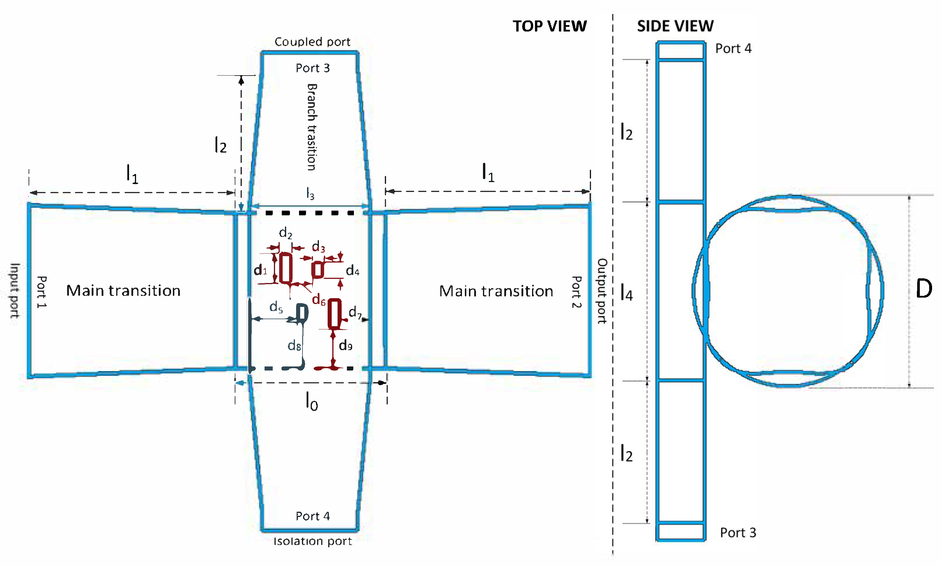
Figure 1. The coupler consists of a circular main waveguide and a rectangular branch waveguide, which cross at 90-degree angles. The high-power microwave is transmitted in the main waveguide, input from port 1 and output through port 2. A small portion of the microwave energy passes through the coupling slot into the branch waveguide in a certain ratio and can then be obtained at port 3, namely the coupling port. The isolation port (port 4) has almost no microwave power in contrast to port 3, and their difference can thus create a high directivity. The input/output radii of the main waveguide are R = 16 mm for convenient connection with oversized circular waveguide transmission lines. The main waveguide contains a significantly oversized DCW, originating from a circular waveguide with four symmetrical perturbations in the radial direction. The outline of the DCW is defined by analytical equations as follows:
x ( t ) = ( a 0 + a 1 cos 4 t ) sin t y ( t ) = ( a 0 + a 1 cos 4 t ) cos t
where a0 is the average radius of DCW, which should be close to the radius of the circular waveguide, and a1 determines the perturbation degree dependently related to a0. The values of a0 and a1 ought to be selected appropriately to adjust the outline of DCW to guarantee power capacity. Moreover, they also need to be fine-tuned in conjunction with the optimization results of the coupled structure to increase the directivity and bandwidth. Additionally, in this design, a0 is chosen to be 15.5 mm, and a1 is 2.2 mm. The main waveguide and the branch waveguide are connected by a group of azimuthal slots whose length, width, and location are well optimized by PSO. A pair of linear transitions between DCW and circular waveguide is placed to realize the TE11 mode transition in high efficiency.
As shown in Figure 2, the introduction of the DCW changes the shape of the original circular main waveguide, allowing the main waveguide to be slotted along the azimuthal direction. In this case, electric coupling can be achieved in circular waveguide couplers. Additionally, with the help of the DCW, the coupler performs well in polarization discrimination. As indicated in Figure 2b, the electric field distribution of the circular TE11 mode in the DCW focuses only on the opposite sides (X side). The field focus brings two advantages. On the one hand, the focus strengthens the field at the waveguide’s wall, which increases the upper limit of the coupling degree. The adjustment range of the coupling degree is thus enlarged, which helps to obtain the desired coupling degree during the design. On the other hand, the field focus makes it applicable in circularly polarized transmission line. When the polarization direction of the TE11 mode is parallel to the slots’ sides (along the Y side), the mode field is weak, having little impact on the coupling degree. On the contrary, when the TE11 mode is vertical to the slots’ sides (along the X side), the field is much stronger, which is the most significant factor affecting the coupling. Therefore, the considerable difference of field on the waveguide wall makes the coupler suitable for circular polarization application, and the power measured through the coupler is half of the actual power. Moreover, since the DCW is highly similar to the circular waveguide, the transition between them is simple and efficient. Except for the intuitive electric field changes, the introduction of the DCW also contributes to performance advancement, which will be illustrated in the following part.
The branch waveguide consists of a nonstandard rectangular waveguide along with its linear transition to a standard waveguide. A nonstandard rectangular waveguide (20 mm × 7.9 mm), rather than the standard WR62 (15.8 mm × 7.9 mm), is used to match the DCW’s propagation constant β, thereby extending the frequency band for high directivity. In order to enable a convenient connection to the standard transmission line, transitions to WR62 are placed at both ends of the branch waveguide. Relevant configuration parameters are shown in Figure 1.
The main and branch waveguides are connected through four rectangular slots. As shown in Figure 1, the slots are arranged in a centrosymmetric manner at the center of the DCW to achieve high directivity. Through the slots, signals transmitted in the main waveguide excite equivalent electric dipoles, which allow the circular TE11 mode in the main waveguide to couple into the rectangular TE10 mode in a controlled proportion. By optimizing the slot geometry, these electric dipoles can contribute to high directivity and a stable coupling degree over a broad bandwidth. Here, the rectangular slots, rather than the commonly crossed apertures that are generally used in the Moreno coupler, are employed to improve polarization discrimination. Unlike the crossed apertures, the rectangular slots can suppress the TE11 mode, whose polarization aligns parallel to the slots, preventing excitation of the dipoles. Note that all slots are chamfered to reduce effects caused by structural irregularities, such as reflection, reducing machining requirements.
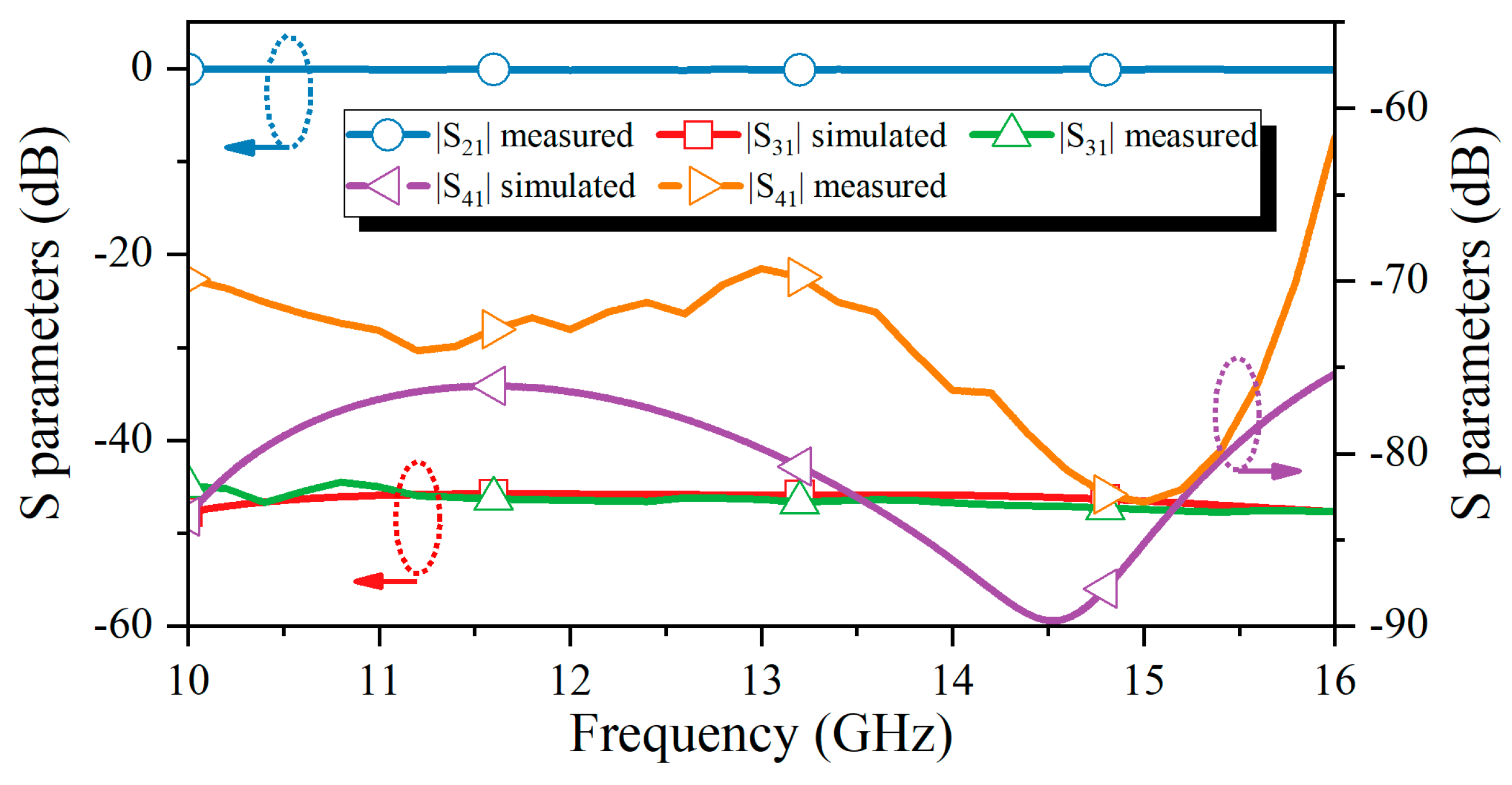
The simulation results of the directional coupler and its electric field distribution pattern at 13 GHz are depicted in Figure 3. The high directivity is observed, as the signal in the branch waveguide exits only through Port 3, while Port 4 shows minimal field distribution. The performance of the coupler is shown in Figure 3, where the transmission efficiency of the TE11 mode in the main waveguide is greater than −0.05 dB, and the port reflection is below −40 dB in the frequency range of 10 GHz to 16 GHz. The transmission and reflection results indicate that the high-power millimeter wave suffers little loss in the proposed directional coupler. Moreover, the coupling degree is stable around −46.5 dB, varying from −45.7 dB to −47.5 dB, while the isolation degree is less than −75 dB. In this case, high directivity greater than 28 dB is achieved from 10 GHz to 16 GHz.
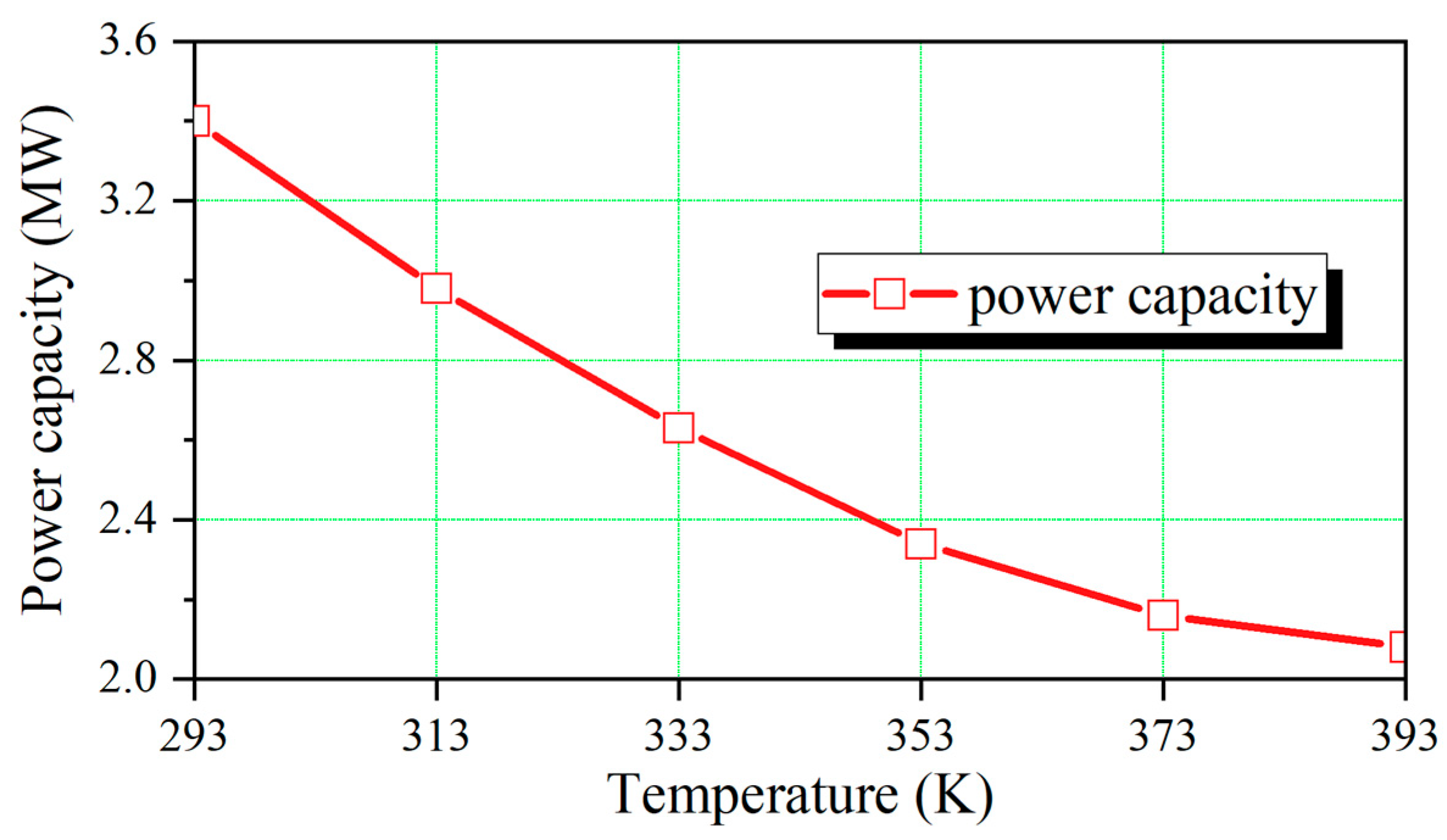
The power capacity of the waveguide directional coupler is investigated as well to guarantee its feasibility in high-power systems. Since passive devices in high-power systems usually have a temperature rise during operation, which also affects the breakdown threshold, the breakdown thresholds of devices in the temperature range of 293 K to 393 K are analyzed. Here, the background gas is set as dry air, and the air pressure is set to atmospheric pressure. The power capacity results are shown in Figure 4. It is clear that the power capacity of the directional coupler is over 2.03 MW in the temperature range of 293 K to 393 K. Considering that the output power of a gyro-TWT is only a few hundred kilowatts at most, the proposed directional coupler is able to work in the gyro-TWT system stably.
In order to explain the merit of the DCW, two extra directional couplers based on normal waveguide structures are designed, of which the DCW is replaced by a circular waveguide and a square waveguide, respectively, as shown in Figure 5. Other parameters of these directional couplers, including the branch waveguide and the size or distribution of coupling holes, are kept unchanged. The coupling degree, the isolation degree, and the directivity of these couplers are displayed in Figure 6, Figure 7, and Figure 8, respectively. Here, the transmission efficiency and the port reflection are not exhibited, as these couplers are all low in propagating losses due to their highly oversized main waveguides. As shown in Figure 6, the coupler based on a circular waveguide has an obviously small coupling degree, of which the highest value is only −52 dB. The peak coupling degree of the circular coupler is much smaller than that of the DCW or square waveguide coupler, which is around −46.5 dB, as the circular waveguide cannot focus the electric field into the coupling area. The low coupling degree requires a more sensitive power measurement device, increasing the realization difficulty of power monitoring. Therefore, the circular waveguide is not suitable for designing the cross-type directional coupler.
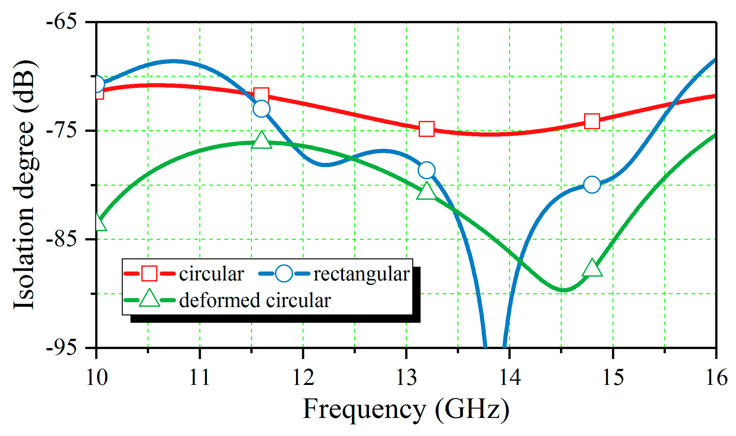
As for the square waveguide coupler, its coupling degree is highly similar to the DCW coupler, according to Figure 7. However, it can be concluded from 
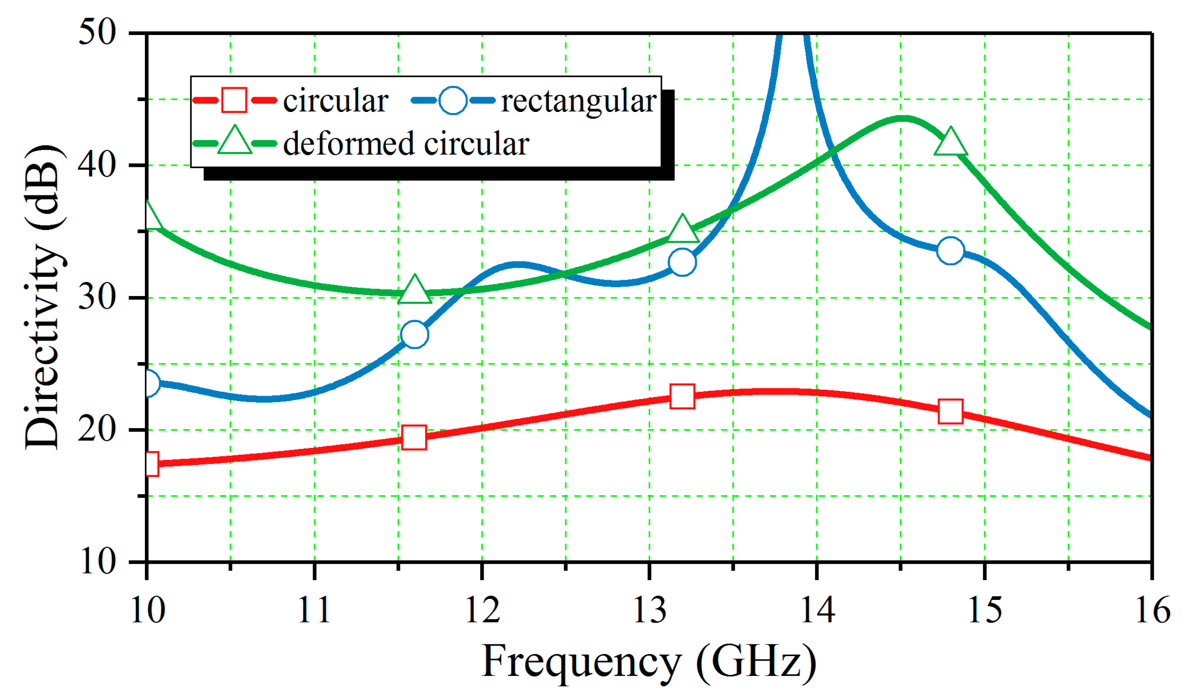
Figure 7 that the isolation degree stability of the square waveguide coupler is inferior to the DCW coupler. In the frequency range of 10 GHz to 16 GHz, the average isolation degree of the square waveguide coupler is −75.6 dB, which is more than 3 dB higher than the DCW coupler, whose average isolation degree is −78.8 dB. As a result, the DCW coupler has a better directivity than the square waveguide, as shown in Figure 8. The average directivity of the DCW is 32 dB, while that of the square waveguide is only 28.8 dB. Obviously, using the DCW can help increase the directivity of a directional coupler.
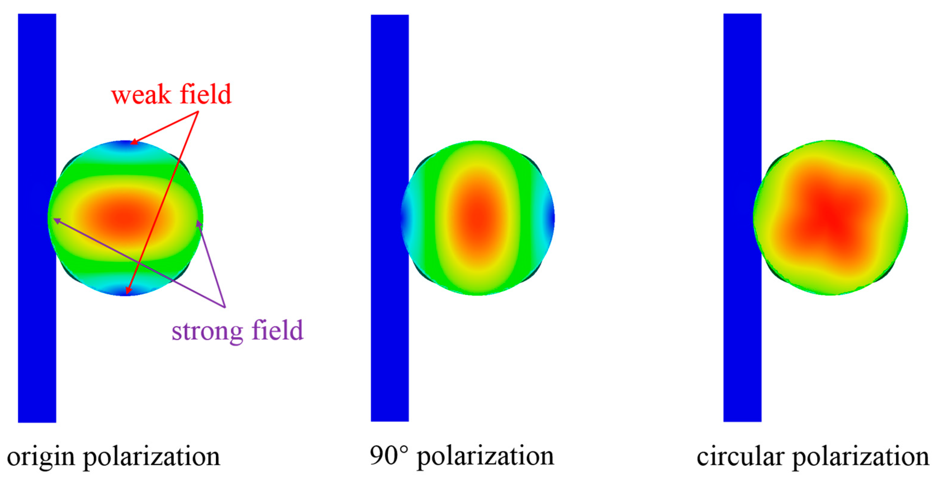
Due to the field focusing characteristic of the DCW, the side wall field of the working TE11 mode concentrates along the direction parallel to the coupling holes, while the side wall field in the transverse direction, which is perpendicular to the coupling holes, is weak, as shown in Figure 9. The selectivity characteristic of the field direction suggests that the coupler has a strong capability for polarization discrimination, which makes it potentially applicable in circularly polarized transmission systems. To demonstrate its polarization discrimination ability, the directional coupler is inputted by two different linear polarization TE11 modes, of which the polarization angular difference is π/2, and the result is shown in Figure 10. The original polarization is defined when the polarization direction of TE11 mode is perpendicular to the rectangular slots, distinguished from the other polarization mode, which is parallel to the slots (referred to as 90° polarization). It is apparently shown in 
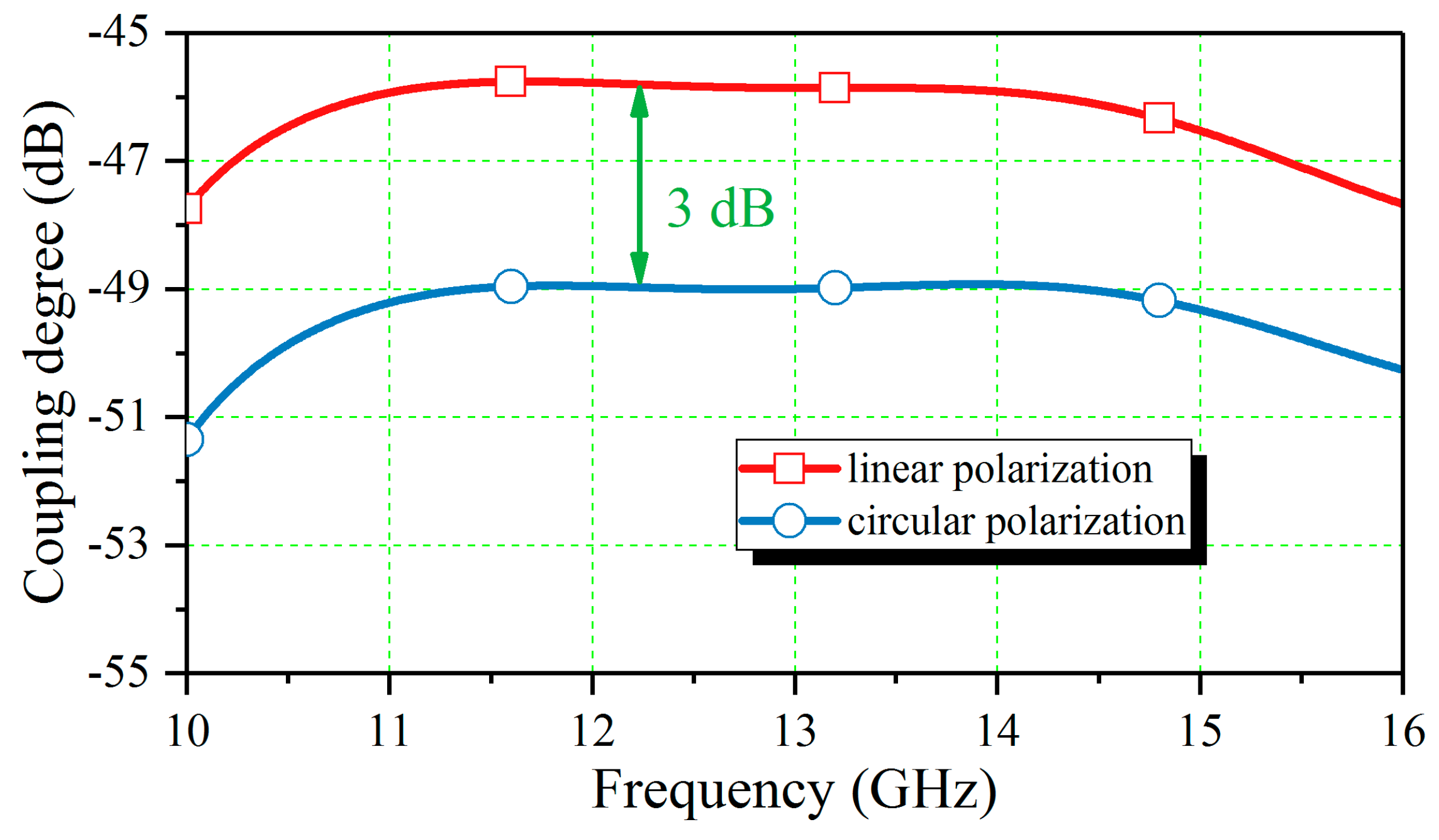
Figure 5 that polarization discrimination is achieved since the coupling degree of the origin polarization is at least 13 dB larger than the 90° polarization, whose coupling degree is around −61 dB. Due to the polarization discrimination ability, the proposed directional coupler is able to work in a circularly polarized system. As shown in Figure 11, the coupling degree results of the directional coupler, which is inputted by a linearly polarized TE11 mode and a circularly polarized TE11 mode, are exhibited. Clearly, the results lines are mostly parallel. The coupling degree of the linear polarization is around 3 dB higher than the circular polarization in the frequency range of 10 GHz to 16 GHz, and the maximum fluctuation is only 0.5 dB, which occurs at 16 GHz. Therefore, the capability of the coupler to work in a circular polarization system is verified, and power monitored through the coupler can be regarded as half of the real one.
For a component working in an oversized waveguide transmission line, the effect of parasitic modes on the directional coupler should be investigated. In a high-power transmission line, shape transformation or discontinuity, such as bends or connection flanges, can result in the generation of parasitic mode [15,16,17,
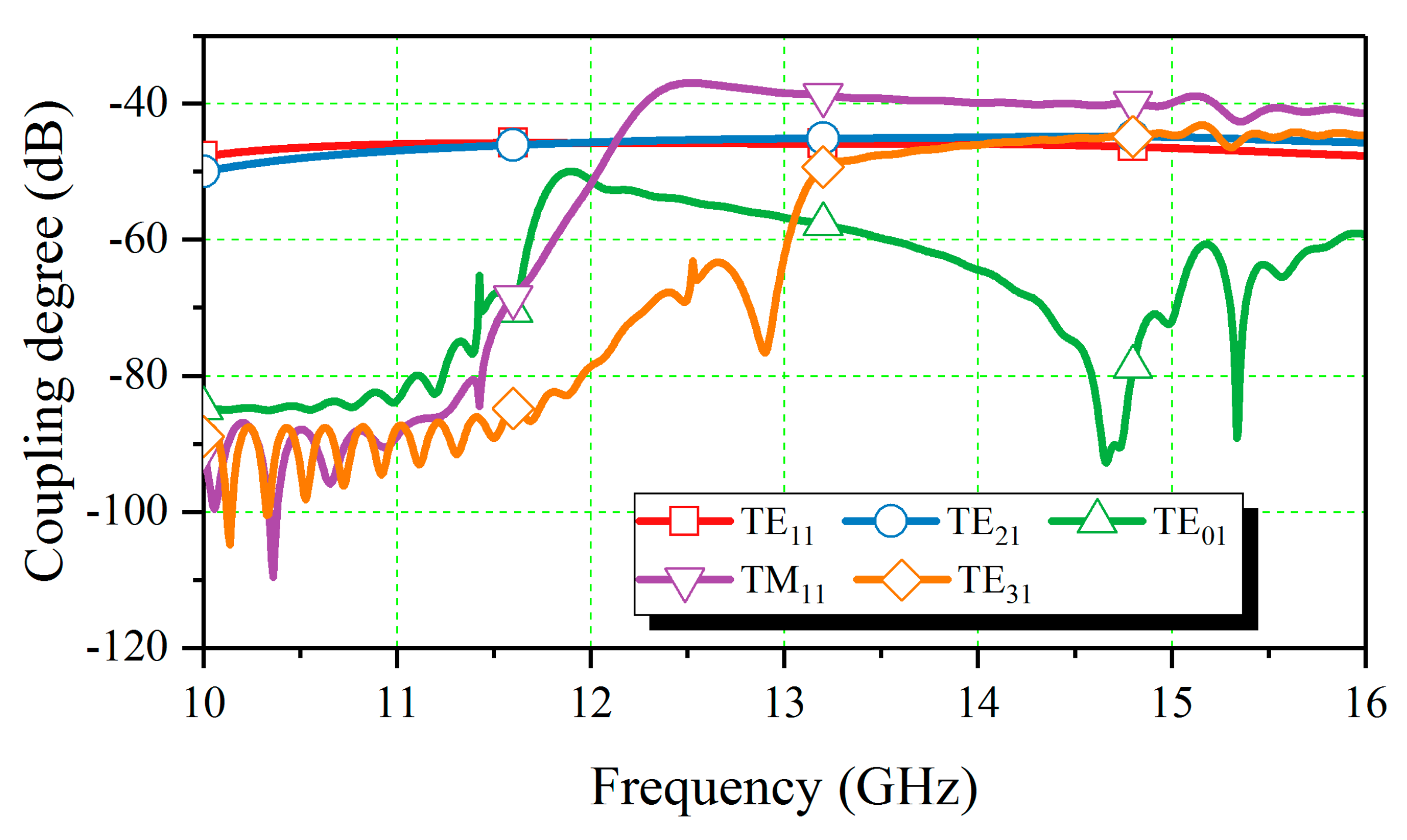
18]. Moreover, the output of the gyro-TWT itself may contain parasitic modes as well. Therefore, estimating the directional coupler’s performance under parasitic mode input conditions is necessary. In this part, several typical parasitic modes in the oversized circular waveguide transmission lines operating in TE11 mode, including the TE21, TE31, TM11, and TE01 modes, are selected for investigation. In Figure 12, the coupling degree of the proposed directional coupler with different input modes is displayed. It can be clearly seen that the results of TE21 mode are mostly identical to those of TE11 mode. The TM11 mode is cut-off under 12 GHz, yet the coupling degree of it increases rapidly around 12 GHz and exceeds that of the TE11 mode in the frequency range of 12.3 GHz to 16 GHz. The TE01 mode is also cut off under 12 GHz. However, its coupling degree only reaches a peak value of −50 dB at 11.9 GHz and then decreases rapidly. The TE31 becomes a propagating mode over 13 GHz, and its coupling degree between 13 GHz and 16 GHz is also similar to the TE11 mode. In addition to the coupling degree, the isolation degree of the coupler with parasitic mode inputs is also analyzed, as shown in Figure 13. Clearly, the isolation degree results of the parasitic modes are much more than that of the operating TE11 mode. For example, though similar in coupling degree, the TE21 mode’s isolation degree is around −60 dB, which is over 10 dB higher than the TE11 mode’s results, which is around −80 dB. The TM11 mode has the highest isolation degree, ranging from −50 dB to −40 dB, which is considerably close to its coupling value.
To illustrate the parasitic modes’ influence on the directional coupler further, the directivity of the coupler input by the operating mode and the parasitic modes is investigated, as shown in Figure 14. It can be concluded that the operating TE11 mode has the highest directivity. The directivity results of the parasitic modes are much lower than that of the TE11 mode, with values mostly under 20 dB. For an intuitive demonstration of the parasitic modes’ effects on the directivity, the electric fields in the branch waveguide when the coupler is inputted by these concerned modes are exhibited in Figure 15. It can be observed that only the TE11 mode can converge the power unidirectionally to the coupling port. The TE01 mode has no clear field direction, while the other parasitic modes all have negligible power flow toward the isolation port. Therefore, the parasitic modes have a strong impact on the directivity performance of the directional coupler. They are able to affect the coupling degree to different extents, thus interfering with the accuracy of power monitoring. Meanwhile, due to the deterioration of directivity, the power of parasitic modes can be transmitted to the isolation port, which poses a significant challenge to load stability in high-power applications. Hence, extra consideration should be taken to protect the isolation end. In conclusion, according to the above analysis, the proposed directional coupler is able to monitor the whole power of the transmission line even in the case of parasitic mode interference since its coupling degrees for both the operating mode and the parasitic ones are similar.
For comparison purposes, the proposed directional coupler is compared to other designs in terms of directivity, bandwidth, and size, as shown in Table 1. Note that since some of the designs are not designed for high-power applications and are not developed based on oversized waveguides, there is no need to compare their dimensions with this design. According to the comparison, the proposed directional coupler is high in directivity, and the corresponding bandwidth is also broader than most of the designs. Especially compared with the high-power directional coupler in [5], the size of the proposed directional coupler is reduced on a large scale, indicating the compact feature of this design.

3. Measurement and Result

In order to validate the design, a prototype of the proposed directional coupler is manufactured. The material of the prototype is aluminum, and the structure of it is processed by high-precise machining. Figure 16 shows the prototype and the measurement devices. Here, a frequency spectrograph, a signal source, TE11 mode exciters, and a matched load for WR62 are used. A pair of converters between the coaxial line and the rectangular waveguide is utilized as well to connect the device with the measurement instrument. To match the output port of the main waveguide and reduce port reflection, a termination is set at the end of the main waveguide.
Measured performances of the coupler, including coupling and isolation degree, are shown in Figure 17. For comparison purposes, the corresponding results of the simulation are also presented. In the frequency range of 10 GHz to 16 GHz, the transmission efficiency of the main waveguide (|S21|) is over −0.15 dB, which demonstrates the low loss. The measured |S31|, namely, the coupling degree, is in accordance with the same that is simulated, with a discrepancy maximum of 1 dB. However, the discrepancy in |S41| is much larger since the measured |S41| is over 5 dB greater than the simulation. This is because the termination we used here is not well performed, which has a strong impact on isolation degree. Still, it can be concluded that a directivity of about 22 dB in the broad frequency range of 10 GHz to 15.5 GHz (corresponding fractional bandwidth is 43.1%) has been acquired in this measurement, and the S31 is stable around −46.7 dB with a fluctuation under 0.9 dB, which makes the directional coupler suitable to work in high power transmission line.

4. Conclusions

This paper proposed the design of a broadband directional waveguide for high-power applications based on the oversized circular waveguide transmission line. The main waveguide of the coupler is composed of a deformed circular waveguide, by which the appropriate coupling and high isolation degree can be achieved in a broad bandwidth. Benefiting from the polarization isolation characteristics brought about by DCW, the designed couplers are also suitable for circularly polarized systems. Meanwhile, a compact size can be realized due to the cross-guide structure that is constructed with the help of the deformed circular waveguide. A prototype is designed, fabricated, and measured. Simulation results indicate that a high directivity over 28 dB can be achieved in the wide frequency range of 10 GHz to 16 GHz. Moreover, the applicability of couplers in transmission systems containing parasitic modes is also demonstrated. The performance of the coupler is eventually verified by measurement, of which the results are identical to the simulation. The proposed design provides a novel approach for achieving high-performance directional couplers with high efficiency and high directivity in high-power systems.

Author Contributions

Conceptualization, M.W. and X.L.; methodology, M.W. and X.L.; software, M.W.; validation, M.W. and X.L.; formal analysis, M.W.; investigation, M.W. and X.L.; resources, M.W. and X.L.; data curation, M.W.; writing—original draft preparation, M.W.; writing—review and editing, P.L. and Z.L.; visualization, M.W. and X.L.; supervision, W.L.; project administration, M.W.; funding acquisition, X.L. All authors have read and agreed to the published version of the manuscript.

Funding

This research was funded by National Nature Science Foundation of China under grant number 62201270.

Data Availability Statement

The original contributions presented in this study are included in the article. Further inquiries can be directed to the corresponding authors.

Conflicts of Interest

The authors declare no conflict of interest.

References

  1. Chu, K.R. The electron cyclotron maser. Rev. Mod. Phys. 2004, 76, 489–540. [Google Scholar] [CrossRef]
  2. Pershing, D.; Nguyen, K.; Calame, J.; Danly, B.; Levush, B.; Wood, F.; Garven, M. A TE11 Ka -band gyro-TWT amplifier with high-average power compatible distributed loss. IEEE Trans. Plasma Sci. 2004, 32, 947–956. [Google Scholar] [CrossRef]
  3. Xu, Y.; Mao, Y.; Wang, W.; Luo, Y.; Wang, J.X.; Yan, R.; Yao, Y.; Jiang, W.; Liu, G.; Li, H. Proof-of-principle experiment of a 20-kW-average-power Ka-band gyro-traveling wave tube with a cut-off waveguide section. IEEE Electron Device Lett. 2020, 41, 769–772. [Google Scholar] [CrossRef]
  4. Song, H.H.; McDermott, D.B.; Hirata, Y.; Barnett, L.R.; Domier, C.W.; Hsu, H.L.; Chang, T.H.; Tsai, W.C.; Chu, K.R.; Luhmann, N.C., Jr. Theory and experiment of a 94 GHz gyrotron traveling-wave amplifier. Phys. Plasmas 2004, 11, 2935–2941. [Google Scholar] [CrossRef]
  5. Liu, G.; Luo, Y.; Wang, J. Design of a composite multi-aperture array circular directional coupler for high power gyrotron. In Proceedings of the 2012 International Workshop on Microwave and Millimeter Wave Circuits and System Technology, Chengdu, China, 19–20 April 2012. [Google Scholar]
  6. Zhu, Z.; Zhao, G.; Xu, Y.; Fan, X. Design of compact double-ridge waveguide directional coupler. In Proceedings of the 2023 International Conference on Microwave and Millimeter Wave Technology (ICMMT 2023), Qingdao, China, 14–17 May 2023. [Google Scholar]
  7. Deng, X.; Wang, Z.; Xu, K.; Yan, B. Compact full Ka-band waveguide directional coupler based on large aperture array. Electron. Lett. 2016, 52, 936–937. [Google Scholar] [CrossRef]
  8. Aja, B.; Villa, E.; de la Fuente, L.; Artal, E. Double square waveguide directional coupler for polarimeter calibration. IEEE Trans. Microw. Theory Tech. 2019, 67, 1840–1849. [Google Scholar] [CrossRef]
  9. Zhang, Y.; Wang, Q.; Ding, J. A cross-guide waveguide directional coupler with high directivity and broad bandwidth. IEEE Microw. Wirel. Compon. Lett. 2013, 23, 581–583. [Google Scholar] [CrossRef]
  10. Tayebi; Zarifi, D.; Nasri, M. Design of X-band Moreno cross-guide coupler based on superformula curves. Int. J. RF Microw. Comput. Aided Eng. 2020, 30, 1–6. [Google Scholar] [CrossRef]
  11. Rectangular Waveguide Cross-Guide Couplers: Accurate Model for Full-Band Operation. IEEE Microw. Wirel. Compon. Lett. 2018, 28, 561–563. [CrossRef]
  12. Gentili, G.G.; Lucci, L.; Nesti, R.; Pelosi, G.; Selleri, S. A novel design for a circular waveguide directional coupler. IEEE Trans. Microw. Theory Tech. 2009, 57, 1840–1849. [Google Scholar] [CrossRef]
  13. Ma, J.; Zhong, W.; Zhang, H.; Zhang, C.; Xu, Z.; Sun, Z.; Chen, D.; Liu, Q.; Shen, Z. A highly directional eight-hole coupling circular waveguide coupler. Int. J. RF Microw. Comput. Aided Eng. 2022, 32, 1–9. [Google Scholar] [CrossRef]
  14. Wang, J.; Tian, Q.; Li, X.; Shu, G.; Xu, Y.; Luo, Y. Theory and experiment investigate of a 400-kW Ku-band gyro-TWT with mode selective loss loading structure. IEEE Trans. Electron Devices 2017, 64, 550–555. [Google Scholar] [CrossRef]
  15. Thumm, M.; Kasparek, W.; Wagner, D.; Wien, A. Reflection of TE0n modes at open-ended oversized circular waveguide. IEEE Trans. Antennas Propag. 2013, 61, 2449–2456. [Google Scholar] [CrossRef]
  16. Lawson, W.; Esteban, M.; Raghunathan, H.; Esteban, M. Bandwidth studies of TE0n-TE0 (n + 1) ripple-wall mode converters in circular waveguide. IEEE Trans. Microw. Theory Tech. 2005, 53, 372–379. [Google Scholar] [CrossRef]
  17. Ceccuzzi, S.; Ponti, C.; Ravera, G.L.; Schettini, G. Physical mechanisms and design principles in mode filters for oversized rectangular waveguides. IEEE Trans. Microw. Theory Tech. 2017, 65, 2726–2733. [Google Scholar] [CrossRef]
  18. Thumm, M.K.; Kasparek, W. Passive high-power microwave components. IEEE Trans. Plasma Sci. 2002, 30, 755–786. [Google Scholar] [CrossRef]
Figure 1. Overview of the proposed directional coupler with dimension. (Configurations parameters are expressed in mm: D = 32, l0 = 25, l1 = 40, l2 = 24, l3 = 20, l4 = 30, d1 = 5, d2 = 1.7, d3 = 2.6, d4 = 1.4, d5 = 8, d6 = 3.8, d7 = 5.1, d8 = 9.8, d9 = 8.4).
Electronics 14 02652 g001
Figure 2. Shape difference and field pattern of the TE11 mode in (a) circular waveguide; (b) deformed circular waveguide (DCW).
Electronics 14 02652 g002
Figure 3. S parameters and electric field distribution of the coupler.
Electronics 14 02652 g003
Figure 4. The power capacity of the coupler.
Electronics 14 02652 g004
Figure 5. Similar directional coupler with different main waveguide parts. (a) DCW; (b) circular waveguide; (c) square waveguide.
Electronics 14 02652 g005
Figure 6. Coupling degree of the couplers with different main waveguide parts.
Electronics 14 02652 g006
Figure 7. Isolation degree of the couplers with different main waveguide parts.
Electronics 14 02652 g007
Figure 8. Directivity of the couplers with different main waveguide parts.
Electronics 14 02652 g008
Figure 9. Schematic diagram of the proposed directional coupler with different polarized TE11 mode inputs.
Electronics 14 02652 g009
Figure 10. S parameters of couplers with different polarized TE11 mode inputs.
Electronics 14 02652 g010
Figure 11. Coupling degree of the directional coupler with linearly or circularly polarized inputs.
Electronics 14 02652 g011
Figure 12. Coupling degree of the directional coupler with parasitic modes inputs.
Electronics 14 02652 g012
Figure 13. Isolation degree of the directional coupler with parasitic modes inputs.
Electronics 14 02652 g013
Figure 14. Directivity of the directional coupler with parasitic modes inputs.
Electronics 14 02652 g014
Figure 15. Electric field distribution in the branch waveguide of the proposed DCW directional coupler.
Electronics 14 02652 g015
Figure 16. Measurement of the waveguide directional coupler.
Electronics 14 02652 g016
Figure 17. Measured results of the waveguide directional coupler.
Electronics 14 02652 g017
Table 1. Comparison of the proposed directional coupler with other studies.
ReferenceFractional BandwidthDirectivitySize (Length)Oversized Degree
[5]>11.8%>27 dB15λ × 4λ × 5λOversized
[6]75.8%>20 dB\Not oversized
[7]41.3%>10 dB\Not Oversized
This work46.1%>28 dB4 × λ × 2.6λ × 1.3λOversized
Disclaimer/Publisher’s Note: The statements, opinions and data contained in all publications are solely those of the individual author(s) and contributor(s) and not of MDPI and/or the editor(s). MDPI and/or the editor(s) disclaim responsibility for any injury to people or property resulting from any ideas, methods, instructions or products referred to in the content.

