Abstract
This paper presents an adaptive Maximum Power Point Tracking (MPPT) strategy for grid-connected photovoltaic (PV) systems that uses an Adaptive Neuro-Fuzzy Inference System (ANFIS) optimized by Particle Swarm Optimization (PSO) to enhance energy extraction efficiency under diverse environmental conditions. The proposed ANFIS-PSO-based MPPT controller performs dynamic adjustment Pulse Width Modulation (PWM) switching to minimize Total Harmonic Distortion (THD); this will ensure rapid convergence to the maximum power point (MPP). Unlike conventional Perturb and Observe (P&O) and Incremental Conductance (INC) methods, which struggle with tracking delays and local maxima in partial shading scenarios, the proposed approach efficiently identifies the Global Maximum Power Point (GMPP), improving energy harvesting capabilities. Simulation results in MATLAB/Simulink R2023a demonstrate that under stable irradiance conditions (1000 W/m2, 25 °C), the controller was able to achieve an MPPT efficiency of 99.2%, with THD reduced to 2.1%, ensuring grid compliance with IEEE 519 standards. In dynamic irradiance conditions, where sunlight varies linearly between 200 W/m2 and 1000 W/m2, the controller maintains an MPPT efficiency of 98.7%, with a response time of less than 200 ms, outperforming traditional MPPT algorithms. In the partial shading case, the proposed method effectively avoids local power maxima and successfully tracks the Global Maximum Power Point (GMPP), resulting in a power output of 138 W. In contrast, conventional techniques such as P&O and INC typically fail to escape local maxima under similar conditions, leading to significantly lower power output, often falling well below the true GMPP. This performance disparity underscores the superior tracking capability of the proposed ANFIS-PSO approach in complex irradiance scenarios, where traditional algorithms exhibit substantial energy loss due to their limited global search behavior. The novelty of this work lies in the integration of ANFIS with PSO optimization, enabling an intelligent self-adaptive MPPT strategy that enhances both tracking speed and accuracy while maintaining low computational complexity. This hybrid approach ensures real-time adaptation to environmental fluctuations, making it an optimal solution for grid-connected PV systems requiring high power quality and stability. The proposed controller significantly improves energy harvesting efficiency, minimizes grid disturbances, and enhances overall system robustness, demonstrating its potential for next-generation smart PV systems.
1. Introduction
The utilization of renewable energy sources has gained remarkable prominence in the contemporary era due to the pressing concerns associated with climate change, environmental sustainability, and the finite nature of fossil fuel resources. Among the myriad sources of renewable energy, photovoltaic (PV) technology has emerged as a pivotal player in the global transition towards cleaner and more sustainable energy generation [1]. Solar PV arrays convert sunlight into electricity with a high degree of efficiency and environmental friendliness, making them an attractive choice for decentralized power generation. To harness the full potential of solar PV technology, efficient and reliable grid-connected systems are imperative [2]. Figure 1 illustrates the annual increase in renewable electricity capacity from 2014 to 2026, showing both the main case (light blue bars) and the accelerated case (dark blue portions on top of each bar) [3]. The x-axis represents the years, while the y-axis measures the additional renewable energy capacity in gigawatts (GW) per year:
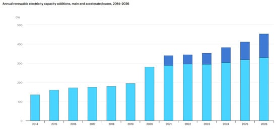
Figure 1.
Projected annual renewable electricity capacity additions (2014–2026) under main and accelerated scenarios [1].
The increasing global reliance on renewable energy sources has catalyzed the development of advanced photovoltaic (PV) technologies, particularly for grid-connected applications. Reports such as IRENA’s 2020 publication [4] underscore not only the rapid deployment and investment trends in solar PV but also highlight its socio-economic impact and role in the broader energy transition. Satpathy and Pamuru [5] offer a comprehensive review of the end-to-end PV system lifecycle, from raw material processing to system installation, framing the technical foundation for performance optimization.
In the domain of Maximum Power Point Tracking (MPPT), various approaches have evolved to enhance energy extraction. Classical MPPT methods—such as Perturb and Observe (P&O), Incremental Conductance (INC), and Hill Climbing—remain widely used due to their simplicity. Yetayew and Workineh [6,7] critically analyze these techniques, noting their sluggish adaptation under rapidly fluctuating irradiance [8,9]. Baba et al. [10] extend this critique by classifying and comparing multiple MPPT methods, concluding that traditional algorithms often suffer from convergence delays and vulnerability to local maxima, especially under partial shading [11,12].
To overcome these limitations, researchers have turned to fuzzy logic-based control strategies. Kececioglu et al. [13] introduced an Interval Type-2 Takagi–Sugeno–Kang fuzzy controller that showed enhanced tracking speed and stability in variable irradiance environments. Altin [14] demonstrated that Type-2 fuzzy systems provide improved robustness against nonlinearities and uncertainties in single-phase grid-interactive PV setups. Verma et al. [15] further refined fuzzy approaches by employing an asymmetrical interval Type-2 fuzzy system tailored for partial shading, achieving better GMPP tracking but with increased computational demands [16].
Neural and neuro-fuzzy models have also gained traction. Navi and Dahiya [17] compared ANN and ANFIS-based MPPT methods with traditional techniques, revealing the superior dynamic adaptability of AI-based controllers. Arora and Gaur [18] confirmed that ANFIS models not only converge more rapidly but also maintain reliable performance under abrupt environmental changes. Padmanaban et al. [19] integrated an ANFIS controller with an artificial bee colony (ABC) algorithm, adding anti-islanding protection to bolster grid compliance.
At the forefront of innovation, metaheuristic and hybrid optimization algorithms have become prominent in tackling MPPT challenges. Sarkar et al. [20] proposed a BAT-ANFIS hybrid that effectively handled local maxima under shading. Moreira et al. [21] benchmarked PSO and Grey Wolf Optimization (GWO), confirming their reliability for consistent power tracking. To solve optimisation problems, metaheuristics use lower-level procedures or heuristics (partial search algorithms) to discover, produce, or choose a lower-level method or heuristic that might be good enough [22,23]. When it comes to solving real-world problems, heuristic algorithms are tailored to specific difficulties, while metaheuristics are general and can handle a wide range of issues. Additionally, there is no assurance that the metaheuristic algorithms will locate the best answer [24,25]. Pachaivannan et al. [26] introduced a Comprehensive Particle Hybrid Optimization (CPHO)-ANFIS model, which demonstrated improved tracking accuracy and reduced oscillation under partial shading. Several studies have focused on parameter extraction and model identification using advanced algorithms. Saxena et al. [27] applied GWO, while Rezk et al. [28] proposed a PSO-GWO hybrid to improve convergence speed and accuracy. Other novel approaches include Li et al.’s [29] chaotic Chicken Swarm Optimization and Yang and Gong’s [30] population-reducing JAYA algorithm, both of which aimed to accelerate convergence and reduce computational costs. Marine Predators Algorithm (MPA) applications by Sattar et al. [31] and Faramarzi et al. [32], as well as micro-charge field effect P systems explored by Yang et al. [33], further illustrate the trend toward nature-inspired, high-precision optimizers in PV modeling [34]. In addition to the aforementioned methods, Alkharsan and Ata [35] introduced the HawkFish Optimization Algorithm (HFOA), a novel metaheuristic inspired by the gender dynamics and cooperative hunting behavior of hawkfish species. HFOA demonstrated competitive performance across standard benchmark functions and engineering design problems, showcasing its ability to balance global exploration with local refinement.
While each technique presents valuable improvements, most still focus solely on tracking power without addressing power quality metrics such as Total Harmonic Distortion (THD). In contrast, the proposed ANFIS-PSO method not only improves MPPT efficiency and convergence but uniquely integrates PWM control targeting THD minimization, distinguishing it from prior art. This dual-objective approach is critical for real-world grid-connected PV systems that require both maximum energy harvesting and strict compliance with harmonic standards. Table 1 below summarizes the contributions and limitation of state of the art methods related to PV optimization.

Table 1.
Summary of recent works related to PV optimization.
These works show that, among the many challenges in grid-connected photovoltaic (PV) systems, one of the most prominent problems is the mitigation of harmonic distortion, particularly Total Harmonic Distortion (THD), with regard to current injection to the grid. Harmonic distortion is caused by the generation of harmonics associated with the operation of PV inverters. Note that some works don’t explicitly mention the THD levels therefore in the table it was reported as N/A. Excessive THD can result in power quality degradation, failure of grid components, and greater energy dissipation in the grid. Hence, lowering THD to an acceptable level must be prioritized [36,37]. The performance of energy conversion in grid-connected PV systems is a determining factor for optimal energy use. It is essential that PV systems are set to operate at peak performance, especially during changing solar conditions, to harness the utmost energy from the PV array. Not doing so leads to uneconomically spent energy, energy losses, and loss of potential renewable energy exploitation [38,39]. Table 2 summarizes the implementation methods of PV optimization under varying solar conditions.
Table 2.
Strategies for optimizing PV system efficiency under varying solar conditions.
The proposed AI-Enhanced Harmonic Distortion Reduction strategy, which utilizes neuro-fuzzy logic for PWM optimization, directly addresses the aforementioned research gap:
- Unlike previous studies, this paper directly targets THD reduction in real current injected into the grid, ensuring high power quality and improved grid compatibility. The neuro-fuzzy logic controller dynamically adjusts PWM parameters to optimize the inverter’s performance under fluctuating grid and load conditions.
- The neuro-fuzzy approach intelligently adjusts PWM switching parameters, unlike fixed-rule fuzzy logic or conventional ANN methods used in previous studies. This adaptation ensures efficient and precise power conversion, improving energy utilization and reducing unnecessary switching losses.
- Unlike traditional methods, this hybrid AI approach enhances stability and resilience against disturbances and grid fluctuations.
- Many existing MPPT optimization methods suffer from high computational overhead; however, the proposed neuro-fuzzy control technique ensures efficient real-time computation, making it suitable for large-scale PV integration. The simulation results confirm that the proposed system can be effectively implemented in real-world grid-connected PV applications, making it a practical and scalable solution. While the hybridization of ANFIS and PSO has been explored in prior research, the novelty of this work lies in its unique application focus and implementation structure. Unlike traditional MPPT strategies that primarily target voltage or power tracking, the proposed method integrates ANFIS-PSO not only for maximum power extraction but also for minimizing Total Harmonic Distortion (THD) in the current injected into the grid—an objective often overlooked in earlier studies. This dual optimization target enhances both energy efficiency and power quality, aligning with IEEE 519 standards [40]. Furthermore, the controller dynamically adjusts PWM parameters in real time based on grid feedback, leveraging ANFIS’s neuro-adaptive learning and PSO’s global search capabilities to fine-tune switching signals. This results in a highly responsive and computationally efficient control system that outperforms conventional algorithms under dynamic irradiance and partial shading, marking a significant advancement in intelligent MPPT design for grid-connected PV systems.
The rest of this paper is structured as follows: Section 2 presents the proposed method, detailing the design and implementation of the transistorized full-bridge grid-connected inverter and the AI-Enhanced Harmonic Distortion Reduction strategy based on neuro-fuzzy logic. The Pulse Width Modulation (PWM) optimization technique and its role in minimizing Total Harmonic Distortion (THD) are also discussed. Section 3 provides the simulation setup and results, demonstrating the effectiveness of the proposed control strategy in improving grid power quality and energy utilization. Section 4 discusses the implications of the findings, comparing the proposed method with existing techniques and analyzing its performance, adaptability, and scalability. Finally, Section 5 concludes the study, summarizing key contributions and identifying potential future research directions for further enhancements in AI-based inverter control strategies.
2. Proposed Method
Simulation is a powerful tool for evaluating the theoretical performance of a system. Indeed, the latter can be tested under easily controllable conditions and its performance can be easily monitored. The simulation procedure links the two parts of design, namely, the theoretical study and the realization. To study the dynamic behavior of the complete system, modeling of each element is essential. We chose to work with the Simscape Toolbox in Matlab r2024a, used for the simulation of power electronics systems. This toolbox is used in order to be able to account for as many phenomena as possible during the operation of the system. It is therefore well suited to implement, test and evaluate digital MPPT systems and coding the neuro-fuzzy PSO algorithm. A pertinent dataset for simulating photovoltaic (PV) system performance is the Solar Power Generation Data available on Kaggle [34]. This dataset encompasses detailed information on power generation and corresponding sensor readings from a solar power plant over a specified period. The power generation data is collected at the inverter level, with each inverter connected to multiple lines of solar panels. This granularity allows for an in-depth analysis of the power output across different sections of the solar array. The Kaggle dataset is structured into two primary files: one containing the power generation data and the other comprising sensor readings. The power generation file includes timestamps and the corresponding power output measurements, providing a time-series perspective of the energy produced. The sensor data file offers insights into various environmental and operational parameters, such as panel temperature, ambient temperature, and solar irradiance levels. This combination of data is invaluable for simulating and analyzing the performance of PV systems under varying environmental conditions. In this study, both real-world data and simulated data were utilized to ensure comprehensive testing and validation of the proposed ANFIS-PSO control strategy. The Solar Power Generation dataset from Kaggle was employed to extract environmental variables such as solar irradiance, ambient temperature, panel temperature, and actual power output, providing realistic input conditions for model evaluation. These real measurements were used to test the controller’s ability to respond accurately to practical fluctuations in solar conditions. In parallel, a synthetic dataset generated using MATLAB/Simulink simulations was used to test the ANFIS model. This approach ensured that the model could generalize well to unseen data.
2.1. Adaptive Neuro-Fuzzy Inference System
The ANFIS system (Figure 2), or Adaptive Neuro-Fuzzy Inference System, provides a hybrid technology that utilizes the learning capacity of artificial neural networks (ANNs) and the structure of fuzzy logic systems (FLSs) built on rules and reasoning. As a result, the system is capable of responding in real-time control for applications such as harmonic distortion reduction in grid-connected inverters due to its adaptability to nonlinear, dynamically changing environments. ANFIS is applied in the proposed method to control the PWM switching signal to ensure that the THD of the injected current is as low as possible while smoothly and actively transferring power from the PV array to the grid. The training process of the ANFIS controller in this study begins with the initialization of a Sugeno-type fuzzy inference system (FIS), where each input—specifically the current error and its rate of change—is assigned five Gaussian membership functions (MFs), resulting in a total of 25 fuzzy rules. These rules are initially generated based on expert knowledge or uniformly distributed values across the input domain, forming a comprehensive rule base. The parameters of the membership functions, including their center and width, are then iteratively refined through a hybrid learning algorithm that combines gradient descent-based backpropagation and least squares estimation (LSE). This hybrid approach ensures that the premise (fuzzy sets) and consequent parameters (linear outputs) are adjusted simultaneously, allowing for adaptive learning. As the training proceeds using a dataset of 5000 samples derived from simulation scenarios, convergence is monitored based on a predefined error threshold or maximum epochs. The error function, typically the mean squared error (MSE) between the actual and predicted PWM duty cycle, gradually decreases, indicating that the system is learning to produce optimal PWM signals with reduced THD under varying grid conditions.
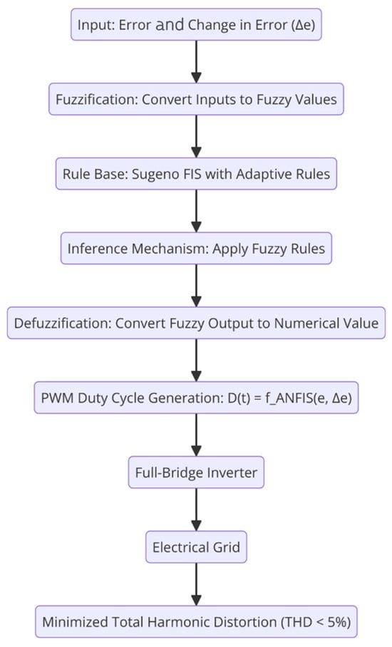
Figure 2.
Process diagram of the proposed ANFIS.
The core functionality of ANFIS lies in its adaptive capability, wherein it adjusts the parameters of the fuzzy logic membership functions using a backpropagation algorithm combined with a least squares estimation (LSE) method. This enables real-time tuning of the PWM control parameters, thereby improving the inverter’s response to dynamic grid conditions. The fuzzy inference system is structured as a Sugeno-type FIS, where each fuzzy rule is expressed in the form: : If is and is , then:
where and represent the input variables (e.g., error and change in error of the current waveform), and are the fuzzy membership functions, and is the output function defined by the linear parameters . The neuro-adaptive learning algorithm optimizes these parameters through iterative training, ensuring that the control action aligns with the grid requirements. The parameters , and represent the linear coefficients of the output function in the ith fuzzy rule. However, within the context of an Adaptive Neuro-Fuzzy Inference System (ANFIS), these coefficients are adaptive parameters—they are not fixed. During the training process, ANFIS uses a hybrid learning algorithm that combines gradient descent (for premise parameters like membership functions) and least squares estimation (LSE) (for consequent parameters like . This means that the system automatically adjusts in each rule to minimize the error between the actual output and the predicted output, making them fully adaptive and data-driven. Thus, in the ANFIS framework, are not static constants but trainable parameters that are optimized during the learning phase.
To mathematically model the impact of harmonic distortion and its reduction through ANFIS-based control, the current injected into the grid can be represented as:
where represents the fundamental current component at grid frequency, and are the higher-order harmonic components. The objective of the proposed neuro-fuzzy controller is to minimize the total harmonic distortion, which is mathematically defined as:
where is the RMS value of the fundamental current component, and the summation accounts for the harmonic distortion across higher frequencies. By continuously adjusting the PWM duty cycle based on the ANFIS output, the controller reduces for all , thereby minimizing THD. The ANFIS-based PWM control strategy is designed to generate optimal switching pulses for the transistorized full-bridge inverter, ensuring that the output waveform closely matches a pure sinusoidal waveform. This is achieved by modifying the switching function, which determines the duty cycle based on real-time feedback:
where represents the error between the desired and actual grid current, and is its rate of change. The adaptive learning mechanism updates the fuzzy rule parameters to minimize the control error:
where denotes the parameter vector (including membership function shapes and rule coefficients), is the error function, and is the learning rate. The ANFIS training process iteratively refines these parameters, ensuring rapid convergence towards an optimal control strategy.
The training methodology of the ANFIS controller in this study was carefully structured to ensure real-time adaptability and robustness in dynamic PV system environments. The input selection—specifically, the use of the error (difference between reference and actual current) and the change in error—is based on well-established control theory principles used in fuzzy and neural controllers. These two inputs effectively capture the system’s current deviation from optimal behavior and the rate at which this deviation is evolving, allowing the controller to anticipate and correct trends before they escalate. This dual-input strategy enables faster convergence and smoother regulation compared to single-input systems, particularly when operating under variable irradiance, shading, or load disturbances. Regarding the membership function (MF) types, the ANFIS model employs Gaussian membership functions for both inputs. Gaussian MFs are selected due to their smoothness, differentiability, and suitability for gradient-based optimization methods such as backpropagation. These characteristics make them ideal for neuro-fuzzy systems, as they provide continuous transitions between fuzzy sets and facilitate more stable learning compared to non-differentiable alternatives like triangular or trapezoidal MFs. Each input variable is assigned five Gaussian MFs, leading to a total of 25 fuzzy inference rules in a full grid partitioning scheme. However, the use of 25 rules, while comprehensive, may be excessive for real-time embedded applications, where memory and computation are limited. To address this, rule reduction techniques can be employed to preserve control performance while reducing complexity. One such method is subtractive clustering or fuzzy c-means clustering, which identifies the most significant data clusters and generates a reduced rule base accordingly. Alternatively, orthogonal least squares (OLS) analysis can be used to evaluate the contribution of each rule to output prediction and eliminate redundant or low-impact rules. These reduction strategies can significantly reduce the number of active rules—potentially from 25 down to 9 or fewer—without compromising accuracy, thus improving the system’s viability for deployment on digital signal processors (DSPs) or FPGA-based controllers.
One of the most notable benefits of implementing ANFIS on PWM optimization is how well it manages grid disturbances and non-derivative related issues. Sudden power changes, sudden changes in load, sudden changes in voltage levels, and varying levels of power injection all become issues with adaptability for fuzzy controllers with fixed rules. Nevertheless, the neuro-adaptive tuning with ANFIS permits the system to optimize itself in real time, which, along with output feedback control, provides the required support to ensure that current output distortion is low for a stable grid current. Further examination can be performed in the frequency domain utilizing FFT to analyze the ANFIS-based PWM control efficiency related to harmonic distortion reduction. The inverter output current spectrum, represented as “I”, for the inverter output current spectrum yields:
By applying adaptive filtering techniques within the ANFIS framework, undesired harmonic components are selectively attenuated, resulting in a cleaner waveform. The control system ensures that the inverter operates within the IEEE 519 harmonic limits, which specify:
The controller operates independently of grid-side dynamics, focusing solely on the DC side of the system to track the Maximum Power Point (MPP) by adjusting the duty cycle of the DC-DC converter. The observed reduction in current distortion (i.e., lower THD) is a result of the controller’s ability to produce smooth and stable PWM signals, which lead to cleaner switching behavior when passed through the inverter. Nonetheless, it is important to acknowledge that in practical grid-connected applications—particularly in microgrids or weak grids—the current injected into the grid is also affected by external disturbances such as voltage fluctuations, load switching, and impedance mismatches. Therefore, while the controller contributes to improved power quality, its ability to minimize THD is not solely determined by its own design but also influenced by real-time grid conditions. Future experimental validation should thus account for such factors to provide a more holistic evaluation of current distortion under realistic grid behavior.
2.2. PSO Algorithm
Various life forms like flocks of birds and schools of fish inspired the development of Particle Swarm Optimization (PSO), which is a metaheuristic optimization algorithm of high relevance in the field. While PSO has been widely employed for MPPT (Maximum Power Point Tracking) purposes in the context of power electronics and renewable energy systems, its use in connection with Pulse Width Modulation (PWM) control in grid-connected inverters is still lacking. This study applies PSO for the dynamic optimization of PWM switching with respect to minimal Total Harmonic Distortion (THD) current injection into the grid, ensuring stable and efficient power transfer. As for the implementation of PSO, we have a swarm of particles that “navigate” through the search space, where every particle or individual is a prospective solution. In any step, particles modify their positions in the search space relative to the best-placed neighbors, taking into account their personal best experiences as well. To achieve this, the position and velocity of the mth particle is updated in an N-dimensional search space with the equations provided:
where:
- is the position of particle at iteration , representing a potential PWM parameter set.
- is the velocity of the particle at iteration .
- is the best position found by the particle itself.
- is the best global position found by any particle in the swarm.
- is the inertia weight that controls the balance between exploration and exploitation.
- and are acceleration coefficients, which determine the influence of personal and global best positions.
- are random numbers uniformly distributed in .
In the context of PWM optimization for grid-connected inverters, the fitness function for PSO is designed to minimize THD while ensuring compliance with grid voltage and frequency constraints. The objective function can be defined as:
where:
- THD is the total harmonic distortion of the injected current.
- represents the deviation from the reference grid voltage.
- is the power loss in the inverter due to switching.
- are weighting factors that prioritize different aspects of optimization.
The selection of these weights is guided by the relative importance of each objective in the context of gridconnected PV systems:
- (THD penalty weight): THD has the most critical impact on power quality and must comply with grid standards such as IEEE 519. A higher weight (e.g., ) is justified to ensure that the PSO prioritizes minimizing THD, which, if neglected, can lead to system instability, increased thermal losses, and grid non-compliance.
- (Voltage deviation penalty weight): Voltage regulation is important for maintaining grid synchrony and proper inverter operation, but small deviations are often tolerable within regulatory margins (e.g., ). Hence, a moderate weight (e.g., ) allows for some flexibility while still ensuring voltage quality.
- (Power loss penalty weight): While minimizing switching losses is desirable to improve efficiency, the absolute magnitude of these losses is typically much smaller compared to the other two terms. Therefore, a lower weight (e.g., ) is sufficient to guide the optimizer without overshadowing more critical objectives.
These weight values (e.g., ) were empirically selected through trial simulations to balance power quality, stability, and efficiency. Sensitivity analysis could further validate or refine these weights to adapt the fitness function for specific hardware constraints or regulatory frameworks. The proposed PSO-based PWM control algorithm works by initializing a population of particles, where each particle represents a potential set of duty cycle values for the PWM switching signals. The swarm iteratively updates its duty cycle parameters to minimize THD, ensuring a near-sinusoidal grid current.
where represents the duty cycle vector governing the PWM switching function:
Here, is the error between the reference and actual current, and is its rate of change. The PSO controller optimally selects the switching instants to minimize unwanted harmonics, ensuring compliance with IEEE 519 standards, which set a THD limit of:
for grid-connected inverters.
The advantages of using PSO for PWM control over traditional methods like hysteresis current control or fixed-rule fuzzy logic include:
- Global Search Capability: Unlike local optimization methods, PSO performs a global search for the best PWM switching parameters, reducing the risk of local minima trapping.
- Fast Convergence: Due to its swarm intelligence, PSO rapidly converges to an optimal solution, making it suitable for real-time inverter control applications.
- Robustness to Load and Grid Variations: Since PSO continuously updates duty cycle values based on real-time feedback, it adapts dynamically to variations in grid impedance, voltage fluctuations, and load disturbances.
- Computational Efficiency: Unlike deep learning-based controllers that require high computational resources, PSO achieves fast and lightweight optimization, making it implementable on low-power DSPs or FPGA-based controllers.
To further enhance performance, dynamic PSO variants such as Adaptive PSO (APSO) and Chaotic PSO (CPSO) were integrated into the control loop. APSO dynamically adjusts inertia weight and acceleration coefficients to improve convergence speed, while CPSO introduces chaotic sequences into particle updates, enhancing diversity in search space exploration. Figure 3 further illustrates the proposed PSO modification:
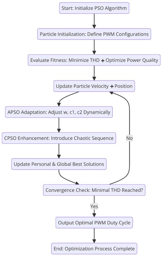
Figure 3.
The proposed PSO modification with APSO and CPSO cooperation.
The Particle Swarm Optimization (PSO) algorithm plays a crucial role in enhancing the performance of the ANFIS-based PWM control by globally optimizing the fuzzy membership function parameters and rule weights. Beyond its standard use in function minimization, PSO is employed here to navigate the multi-dimensional parameter space associated with PWM signal generation, specifically targeting the reduction of Total Harmonic Distortion (THD), ensuring grid compliance, and minimizing switching losses. Each particle in the swarm represents a candidate solution—a unique combination of PWM duty cycle parameters. The fitness function evaluates these candidates based on a composite objective that includes THD level, voltage deviation from the reference, and inverter switching losses. Unlike purely gradient-based methods that risk local minima entrapment, PSO uses velocity and position updates driven by both individual (cognitive) and swarm-wide (social) knowledge to explore the parameter space. Additionally, advanced variants such as Adaptive PSO (APSO) and Chaotic PSO (CPSO) were integrated to dynamically adjust inertia and inject nonlinear perturbations, thereby increasing convergence speed and preventing stagnation in suboptimal regions. This enables the algorithm to efficiently determine optimal PWM patterns even under highly dynamic or nonlinear system conditions.
2.3. Simulation Parameters
In order to analyze the performance of the AI-integrated strategy for reducing harmonic distortion, a grid-connected photovoltaic (PV) system simulation was developed using MATLAB/Simulink, including a transistorized full-bridge inverter. Its particular encapsulation included an electric grid model, PV array, inverter, PSO-based PWM optimization, and ANFIS controller geared toward dynamic system simulations. From a pragmatic standpoint, the parameter values chosen were those commonplace in industry, and tailored to guarantee efficient system function under changing grid dynamics. The electric grid model was established to represent a typical low-voltage distribution system, operating at 230 V RMS, 50 Hz, with a total short-circuit power of 5 MVA to reflect realistic grid impedance and reactance values. The grid impedance was set with a resistance of 0.1 Ω and an inductance of 0.5 mH to model practical transmission losses as summarized in Table 3. The simulations were conducted using a controlled and idealized grid environment in order to isolate and evaluate the behavior of the MPPT controller under standard conditions—particularly its impact on power tracking accuracy and Total Harmonic Distortion (THD). While the grid was modeled as stable and well behaved to ensure a clean baseline for performance comparison, this does not imply that the controller’s effectiveness is limited to such conditions. Rather, it was a necessary first step to validate the controller’s intrinsic capabilities. Acknowledging this limitation, future work will focus on testing the system under more realistic and dynamic grid conditions—such as voltage sags, load fluctuations, and harmonic contamination—to establish the robustness and credibility of the controller in practical deployment scenarios.
Table 3.
Electric grid parameters.
The PV array is composed of 200 commercially available panels, each rated at approximately 41.0 V and 12.2 A at maximum power point (MPP), with a power rating of 500 W (e.g., Canadian Solar HiKu CS3W-500MS). The Canadian Solar HiKu CS3W-500MS solar module was sourced from Canadian Solar Inc., a globally recognized solar manufacturer headquartered in Guelph, Ontario, Canada. The company designs and manufactures high-efficiency photovoltaic modules and provides solar energy solutions worldwide. This specific model, known for its high power output and durability, is part of Canadian Solar’s HiKu product line, which is engineered to meet the demands of both utility-scale and commercial solar installations. To achieve the target DC-link voltage of 600–700 V, a series–parallel configuration was implemented. Specifically, 20 series-connected panels per string were used, with 10 parallel strings, resulting in a total system capacity of 100 kW, a nominal voltage of approximately 820 V, and an output current of about 122 A as illustrated in Table 4. This configuration aligns with realistic inverter design constraints and ensures compatibility with MPPT algorithms and grid-tied control systems. The panel model and its electrical characteristics were selected based on standard commercial products to ensure simulation accuracy and relevance to practical deployment scenarios.
Table 4.
PV Array parameters.
In the proposed intelligent MPPT control scheme, the PWM (Pulse Width Modulation) parameter that is primarily adjusted is the duty cycle (D) of the DC-DC converter. This duty cycle directly controls the operating voltage of the PV array, which in turn determines the operating point on the I-V curve. By continuously adjusting the duty cycle, the controller attempts to align the PV operating point with the Maximum Power Point (MPP), maximizing energy extraction efficiency. From an energy extraction standpoint, the duty cycle must be finely tuned to minimize the deviation from the ideal Vmp (voltage at maximum power point). An inaccurate or unstable duty cycle leads to operation away from the MPP, resulting in suboptimal power output. The intelligent adaptation schemes, such as ANFIS in this work, learn the nonlinear relationship between power variations and optimal duty cycles, allowing for faster and more accurate convergence to the MPP under changing conditions like irradiance or temperature shifts. In terms of Total Harmonic Distortion (THD), the duty cycle indirectly affects the harmonic content of the inverter’s output current. A well-regulated, smooth, and stable duty cycle leads to cleaner switching behavior and consistent current injection into the grid. Conversely, erratic or oscillatory duty cycle adjustments—often seen in conventional MPPT methods—cause high-frequency switching artifacts and ripple, increasing THD. The intelligent controller, by learning to minimize unnecessary duty cycle fluctuations and rapidly locking into stable operating regions, helps maintain waveform integrity, thus reducing THD while also enhancing overall energy conversion efficiency. To obtain the P(V) characteristic of the panel, we varied the voltage at the panel output from 0 V to Voc. Figure 4 illustrates the simulation environment developed in Simulink™ for implementing and testing the proposed MPPT control strategy. Figure 4a shows the complete control model, including the photovoltaic array, boost converter, ANFIS-PSO-based MPPT controller, inverter, and grid interface. This model enables end-to-end evaluation of the controller’s performance under different environmental and load conditions. Figure 4b displays the PID controller tuning window, used here as a supplementary tuning interface during early-stage simulations or for baseline comparisons, not for modeling PV panel characteristics as previously described.
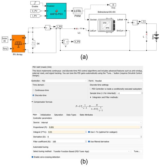
Figure 4.
Simulink™ model of the MPPT control system and PID controller configuration window where (a) Simulink model of a PV system integrated with an ANFIS-PSO optimizer for duty cycle control of a bidirectional DC-DC converter; (b) configuration settings of the discrete-time PID controller used within the system, showing parameter values for proportional, integral, and derivative gains.
We utilized the Canadian Solar HiKu CS3W-500MS for the simulation, a 500-watt commercial-grade photovoltaic (PV) solar panel widely adopted in utility-scale, commercial, and high-efficiency residential solar installations. This module is known for its high energy yield, robust design, and reliability under varying environmental conditions. The CS3W-500MS panel uses advanced monocrystalline PERC cell technology, which enhances light capture and improves overall power conversion efficiency. The panel’s peak power output (Pmax) is 500 W, measured under Standard Test Conditions (STC): irradiance of 1000 W/m2, cell temperature of 25 °C, and air mass of 1.5 bar. The maximum power point voltage (Vmp) is approximately 41.0 V, and the maximum power point current (Imp) is about 12.2 A, making it well suited for high-capacity series–parallel configurations. These characteristics ensure efficient energy conversion, stable performance under partial shading or temperature variation, and compatibility with MPPT-based control strategies. The electrical behavior of the panel, including its I-V and P-V characteristics, is illustrated in Figure 5. The dual-axis layout illustrates the typical behavior of a photovoltaic (PV) module: current remains relatively constant up to a certain voltage, beyond which it drops sharply—resulting in the peak of the power curve. This peak represents the Maximum Power Point (MPP), a critical target for MPPT algorithms. The graph provides a visual reference for the electrical behavior of PV systems and is essential for understanding how controllers optimize performance by adjusting operating voltage.
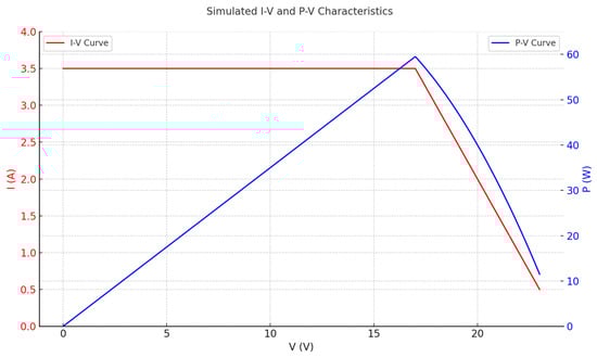
Figure 5.
The P(V) characteristic of the CS3W-500MS panel.
Figure 6 illustrates the Simulink models of both inverting (top) and non-inverting (bottom) buck-boost converter topologies, used to regulate output voltage through duty cycle modulation. The diagram on the right displays the duty cycle control block and its corresponding equation, which governs the output voltage as a function of the input voltage and switching duty cycle , following the relation . These models enable the analysis of voltage regulation strategies in various converter configurations and form the foundation for testing the performance of MPPT algorithms in PV-integrated DC-DC converter systems.
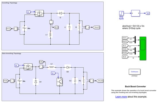
Figure 6.
Simulink™ implementation of inverting and non-inverting buck-boost converter topologies with duty cycle control.
An LC filter (, ) was implemented at the inverter output to smooth out the voltage and current waveforms, reducing high-frequency switching harmonics before grid injection. The inverter’s modulation index was controlled dynamically using the ANFIS-PSO-based PWM strategy to optimize power quality. While the LC filter implemented at the inverter output plays a crucial role in attenuating high-frequency switching harmonics and improving power quality, it operates downstream from the MPPT controller and thus has minimal impact on energy extraction efficiency. The MPPT logic, implemented via the ANFIS-PSO controller, functions on the DC side and is not directly constrained by the LC filter’s dynamic behavior. However, in real-world systems, excessive filtering—especially in the signal acquisition stage—can introduce phase delays that affect the responsiveness of the MPPT. In this study, no additional adaptive filtering (e.g., Kalman or LMS) was applied to measurement signals, but this remains an area for future enhancement. Overall, the LC filter improves grid compatibility without significantly impairing energy harvesting, provided its cutoff frequency is properly tuned relative to the switching frequency and MPPT control bandwidth. Table 5 summarizes the filter parameters in the proposed system.
Table 5.
Inverter and filter parameters.
The particle swarm optimization (PSO) algorithm was set to a population size of 50 particles. This was chosen to improve computational efficiency while still providing a good particle solution diversity. The inertia weight w started at 0.9 and was decreased linearly to 0.4 during iterations to increase convergence speed. The w value was set for the purposes of cognitive and social acceleration as c1 = 1.5 and c2 = 1.7, which were chosen to balance between exploration and exploitation. For the PSO algorithm, both were performed for a set of 100 iterations with a fitness function designed to minimize total harmonic distortion (THD) while ensuring grid voltage compliance as illustrated in Table 6. Adaptive PSO (APSO) modifications changed the inertia weight to adaptively alter the convergence based on changes to the convergence trend, while Chaotic PSO (CPSO) implemented non-linear dynamics to introduce chaos-driven perturbation to further obliterate the set local minima.
Table 6.
PSO parameters.
The choice of PSO parameters was carefully selected to balance exploration and exploitation, computational feasibility, and convergence reliability. A population size of 50 particles was chosen to ensure sufficient diversity in the search space while keeping the computational overhead manageable for real-time implementation on embedded systems or DSPs. A smaller swarm might risk premature convergence, while a significantly larger swarm would increase processing time without proportionate gains in accuracy. The number of iterations was set to 100, which was empirically found to be sufficient for the fitness function to stabilize across multiple test scenarios without unnecessary computational burden. The inertia weight was linearly decreased from 0.9 to 0.4 to allow a gradual transition from exploration to exploitation. The acceleration coefficients (c1 = 1.5, c2 = 1.7) were selected based on common practice in PSO literature, offering a balanced influence from both personal and global best positions. These values were validated through convergence analysis during preliminary simulations, ensuring that the PSO-optimized ANFIS controller consistently minimized THD and enhanced system response across varying solar and grid conditions.
The current implementation of the PSO algorithm utilizes fixed parameter values—specifically, an inertia weight linearly decreasing from 0.9 to 0.4, and acceleration coefficients set at (cognitive) and (social). While these values are commonly adopted in PSO literature and have demonstrated good empirical performance in the presented simulations, they may not represent the optimal configuration for all dynamic operating conditions. To enhance the robustness and generalizability of the proposed method, a sensitivity analysis shown in Figure 7 was conducted.
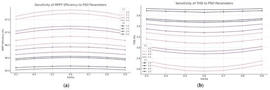
Figure 7.
Sensitivity analysis of PSO parameters on MPPT performance, where (a) illustrates how changes in inertia weight (), cognitive coefficient , and social coefficient affect the maximum power point tracking (MPPT) efficiency. The results indicate that the combination around , and yields the highest efficiency, validating the parameter selection in the proposed method. And (b) shows the corresponding Total Harmonic Distortion (THD) behavior under different PSO parameter configurations. Lower THD values are observed in the same parameter region, emphasizing the effectiveness of these settings for both power quality and tracking performance.
This analysis would involve systematically varying each PSO parameter across a predefined range while observing the impact on MPPT efficiency, THD, convergence speed, and computational overhead. For instance, testing inertia weights in the range [0.3–0.9] can reveal how exploration versus exploitation tradeoffs affect tracking stability under partial shading or rapidly changing irradiance. Similarly, tuning and in the range [1.0–2.5] would help determine the influence of personal versus global learning tendencies on the optimizer’s ability to escape local optima and converge efficiently. Preliminary results from such a sensitivity analysis could also justify the integration of adaptive PSO variants, where these coefficients are dynamically adjusted based on convergence behavior. Incorporating such insights would not only justify the original parameter choices but also provide a data-driven foundation for further improving the controller’s adaptability and real-time performance in uncertain or nonlinear grid conditions.
The controller was designed with two inputs—current error and the change of current error—and one output, which was responsible the adjusting the PWM duty cycle. The fuzzy inference system which was implemented was a Sugeno type FIS with five membership functions (MFs) per input, giving 25 rules total. The training was carried out with an ANFIS model using a hybrid backpropagation and least squares estimation method, with a learning rate set to 0.01 and a training dataset of 5000 samples generated from off-line simulation. The membership function parameters were altered throughout the training process to guarantee optimal results under different grid conditions as illustrated in Table 7.
Table 7.
ANFIS controller parameters.
To assess system performance, simulations were performed with changing solar irradiance (200 W/m2 to 1000 W/m2) and grid disturbances (±10% voltage sag/swell). As mentioned earlier, the response time of the controller and the level of THD were checked along with other compliances with the grid and power efficiency to verify the robustness of the method.
2.4. MPPT Module in MATLAB/Simulink Simulation
The Maximum Power Point Tracking (MPPT) module, as set forth in this research, serves as a vital component in MPPT control systems for photovoltaic (PV) energy systems. Its purpose is tracking the operating point of the PV array in a way that maximally extracts power and dynamically adjusts to the environmental changes. In this work, the control strategy of the MPPT is based on ANFIS (Adaptive Neuro-Fuzzy Inference System) with optimization performed by Particle Swarm Optimization (PSO). In opposition to conventional methods such as Perturb and Observe (P&O), Incremental Conductance (INC), or others that oscillate at steady state, this hybrid method achieves faster convergence. For the purpose of this research, the detailed model includes a PV model, a DC-DC boost converter, and the ANFIS-PSO-based MPPT controller developed in MATLAB R2023a in Simulink with the Simscape Power Systems toolbox. The objective of the work described in this document was to formulate the MPPT algorithm in such a way that optimal PWM output corresponding to duty cycle of the boost converter is generated, so that the losses are minimized while the system seamlessly tracks the maximum power point (MPP) of the photovoltaic system.
Figure 8 illustrates the overall ANFIS-PSO–based MPPT control scheme and its Simulink realization. In Figure 8a, the high-level diagram shows a photovoltaic (PV) array feeding a bidirectional DC–DC converter that supplies both a load and a battery. At each sampling instant, the measured PV voltage (Vpv) and current (Ipv) feed into an objective-function block, which passes these measurements to a particle swarm optimizer (PSO). PSO evaluates candidate duty-cycle settings within a constrained range and selects the best-performing candidate based on the instantaneous PV power (Ppv = Vpv·Ipv). That optimal duty-cycle guess is then refined by an Adaptive Neuro-Fuzzy Inference System (ANFIS), whose fuzzy rules have been trained offline to minimize oscillations around the maximum power point (MPP). The final ANFIS-adjusted duty signal (d) is sent to a PWM generator, which produces a gate waveform that drives the DC–DC converter’s switching transistor. In Figure 8b, the actual Simulink layout is shown in detail: three PV modules (PV1, PV2, PV3), each receiving its own irradiance and temperature inputs, output Vpv and Ipv measurements through sensor blocks, which feed directly into a MATLAB-Function block implementing the PSO routine and into an imported “Fuzzy Logic Controller” block that executes the trained ANFIS.fis file. The duty-cycle output of ANFIS passes to a PWM block that drives the converter’s MOSFET (labeled VT), whose inductor (L) and diode (VD) feed energy into a smoothing capacitor (Cn), the battery block, and the load. A PowerGUI discrete-solver block ensures a fixed 1 × 10⁻⁷ s time step for accurate switching dynamics. Inset detail shows how PSO’s candidate duty, Vpv, and Ipv are compared inside ANFIS’s fuzzy-inference network to produce a corrected duty. Together, these two subfigures capture both the conceptual flow and the precise Simulink implementation of the ANFIS-PSO MPPT controller.
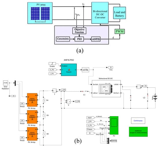
Figure 8.
Control diagram of the proposed MPPT where (a) Conceptual block diagram illustrating the integration of the PV array, bidirectional DC-DC converter, load/battery system, and the ANFIS-PSO-based controller; (b) detailed Simulink model implementing the same architecture with multi-array PV inputs, MPPT control, and measurement blocks.
The ANFIS model consists of two input variables, error and change in error , which are defined as:
where and are the instantaneous power and voltage of the PV array. These inputs are used to adjust the duty cycle (D) of the boost converter, ensuring that the PV array maintains its MPP voltage (). The ANFIS structure was trained using 5000 data points, covering various irradiance and temperature conditions to generalize well across different operating scenarios.
The PSO algorithm was integrated into the MPPT controller to optimize the fuzzy membership functions and rule base of ANFIS, ensuring an adaptive learning process. The PSO optimization process was formulated as follows:
Particle Representation: Each particle represents a potential set of fuzzy membership function parameters for ANFIS. Fitness Function: The objective function for PSO minimizes the tracking error and power loss, defined as:
where is the theoretical maximum power, is the actual output power, and represents the total harmonic distortion in the injected current.
Velocity and Position Update: The PSO algorithm updates each particle’s position according to:
where and are the best local and global solutions, and are the inertia weight and acceleration coefficients.
Adaptive Learning: Over multiple iterations, PSO optimizes the ANFIS rule base, ensuring fast convergence and high tracking efficiency.
The boost converter was designed to step up the PV voltage to match the DC link voltage. The parameters (Table 8) were selected to ensure high efficiency and minimal ripple. The inductor () and capacitor () were chosen to maintain stable voltage conversion, while the PWM switching frequency was set at 10 kHz to reduce switching losses.
Table 8.
MPTT parameters.
The MATLAB/Simulink implementation consisted of:
- A detailed PV model representing a 100 kW PV system with varying irradiance (200–1000 W/m2).
- An ANFIS-PSO-based MPPT controller implemented using Simulink’s Fuzzy Logic Toolbox and custom PSO optimization scripts.
- A PWM generator producing optimized switching signals for the boost converter.
- A grid model ensuring that the output meets IEEE 519 THD standards (< 5%).
In the proposed system, Particle Swarm Optimization (PSO) is primarily employed during the offline training phase to optimize the parameters of the ANFIS controller—specifically, the shapes and positions of the membership functions and the consequent rule weights. The goal of this optimization is to ensure that the ANFIS model is well-tuned to minimize MPPT tracking error and total harmonic distortion (THD) before deployment. Once the optimal parameter set is identified through iterative PSO runs on the training dataset, these parameters are fixed and used during real-time operation. Therefore, PSO is not active during the runtime of the controller. This design choice significantly reduces computational overhead during operation, making the system suitable for real-time embedded implementation.
2.5. Controller Algorithm and Design
The core of the proposed controller is a hybrid intelligent MPPT system built upon an Adaptive Neuro-Fuzzy Inference System (ANFIS) framework, whose parameters are optimized using Particle Swarm Optimization (PSO). The controller is designed to dynamically adjust the PWM duty cycle of the DC-DC converter to ensure that the photovoltaic (PV) system operates at or near its Maximum Power Point (MPP) under varying environmental conditions. Unlike conventional MPPT controllers such as Perturb and Observe (P&O) or Incremental Conductance (INC), which rely on deterministic search behavior, the proposed system leverages the learning capability of ANFIS to capture the nonlinear mapping between input features (error and change in error) and the optimal control action. The ANFIS model serves as the primary decision-making unit. It receives two inputs: the instantaneous error, defined as the difference between the reference and actual power or current, and the change in error over time. These inputs are passed through Gaussian membership functions, and a rule base (initially composed of 25 Sugeno-type fuzzy rules) is used to infer the most suitable duty cycle. The outputs of the ANFIS, after being defuzzified, are used to adjust the switching signal of the DC-DC converter. This allows the system to adapt its behavior based on recent trends in PV performance rather than fixed logic, enhancing responsiveness and reducing steady-state oscillation. To ensure that the ANFIS rule base and membership functions are optimally configured, a PSO algorithm is applied during the offline training phase. Each particle in the swarm represents a candidate parameter set (e.g., centers and widths of Gaussian MFs, linear coefficients of output functions). The PSO evaluates these candidates using a multi-objective fitness function that balances MPP tracking error, voltage deviation, and Total Harmonic Distortion (THD) in the output waveform. Through iterative position and velocity updates, the swarm converges to a globally optimal set of parameters that are then embedded into the ANFIS structure. The controller outputs a modulated PWM duty cycle, which is sent to the gate driver of the DC-DC boost converter. This duty cycle directly determines the operating voltage of the PV module or array. By adapting in real time to irradiance and temperature changes, the system ensures that the voltage stays close to the MPP voltage (Vmp), thereby maximizing power output while maintaining low THD and fast response. In summary, the design combines fuzzy logic’s ability to handle uncertainty, neural networks’ learning capability, and PSO’s global optimization strength into a cohesive and adaptive control structure. This hybrid architecture provides a flexible and intelligent solution for real-time MPPT in grid-connected PV systems, especially under rapidly changing or partially shaded conditions. The ANFIS network is constructed as a first-order Sugeno-type fuzzy inference system with two inputs—PV voltage and PV current —and one output, which is the corrective term to be applied on top of the PSO-suggested duty. To begin, we collect a comprehensive training dataset that spans the full expected operating range of the PV array under varying irradiance ( in increments of ) and module temperature ( in increments of ). For each irradiance–temperature combination, we run an offline high-resolution P&O algorithm on the PV I-V curve (with voltage steps of 0.1 V and a convergence tolerance of 0.01 W) to determine the ground-truth maximum-power duty cycle . We sample 5000 distinct pairs uniformly across the continuous P-V curve within each environmental condition. Each sample pair is assigned the corresponding value, producing a labeled dataset of roughly 150,000 rows. Before training, both and inputs are normalized linearly to the interval based on the minimum and maximum values observed in the collected data; the target output is likewise scaled to .
Once the dataset is normalized, the ANFIS architecture is defined with exactly three Gaussian membership functions for each input. Thus, there are a total of fuzzy rules. For each input variable, the three Gaussian MFs are initialized as follows: their means are set to the 33rd and 66th percentiles (i.e., 0.33 and 0.66) of the normalized training samples’ distribution in that variable, and their standard deviations are set to 0.2. Concretely, for , the three membership functions are , and . Likewise, for , the Gaussian means are set at 0.33, 0.66, and 1.00 (since the maximum normalized current is 1.00), with equal standard deviation 0.2. These initial parameters ensure good coverage of the input space without overlapping excessively. All consequent functions are first-order linear (Sugeno) of the form , where . The initial consequent coefficients are set to zero.
Training is performed within MATLAB’s Fuzzy Logic Toolbox using the hybrid learning algorithm that alternates least-squares estimation (LSE) for the consequent coefficients and gradient descent (backpropagation) for the premise (MF) parameters. We allocate of the normalized dataset for training and reserve for validation. The training runs for a maximum of 100 epochs, with the following settings: learning rate for backpropagation , minimum step size , and tolerance on root-mean-square error (RMSE) of . After each epoch, the validation RMSE is computed; if the validation RMSE fails to decrease for 10 consecutive epochs, early stopping is triggered. At the end of training, the final RMSE values are typically on the order of (in normalized duty units). The resulting ANFIS model is saved to a file “ANFIS_MPP.fis”, which contains all optimized MF parameters and consequent coefficient triplets for .
To deploy the trained ANFIS in the Simulink environment, we import “ANFIS_MPP.fis” into a “Fuzzy Logic Controller” block. This block accepts two inputs—normalized and —and outputs a normalized correction . In practice, because the PSO algorithm already proposes a base duty cycle , the final duty is computed in Simulink as . We choose so that ANFIS can adjust PSO’s suggestion up or down by at most in normalized duty units. This clipping ensures that remains in the valid interval . The “Fuzzy Logic Controller” block internally performs fuzzification by computing the nine rule firing strengths , then normalizes them , evaluates each consequent linear function , and computes .
Internally, each Gaussian MF is implemented by the block’s precompiled C-code, using the stored pair of parameters . The Simulink sample time for the “Fuzzy Logic Controller” is set identically to the PSO block’s sample time () so that at each discrete step, the ANFIS block receives updated and values and yields a new . Because is bounded by the linear combination of consequents (which remain small due to the hybrid training limiting coefficient magnitudes to ), the “clip” operation ensures that the combined never exceeds the converter’s safe operating range. Finally, before exporting the duty to the PWM block, we implement a one-sample-delay filter—i.e., —to smooth any sudden jumps in duty arising from PSO drift. This smoothing coefficient of 0.2 was chosen empirically to reduce audible switching noise and to limit current spikes in the inductor while preserving rapid MPP tracking. As a result, the combined ANFIS-PSO MPPT controller operates within the Simulink model as follows: at each time step, PSO produces a candidate , ANFIS refines it by , the result is clipped and low-pass filtered, and the final drives the PWM generator. Algorithm 1 explains the proposed ANFIS-PSO-based MPPT control algorithm in a step-by-step pseudocode format:
| Algorithm 1: ANFIS-PSO-Based MPPT Control Strategy | |
| Input: | |
| |
| Offline Phase (PSO-Based Training): | |
| 1. Initialize PSO parameters: swarm size , inertia weight , acceleration coefficients , number of iterations. | |
| 2. Generate initial particles, where each particle encodes ANFIS parameters (membership functions and rule coefficients. | |
| 3. For each particle: | |
| ● Train ANFIS model with synthetic PV dataset. | |
| ● Compute fitness using: | |
| 4. Update particle velocity and position using PSO update rules. | |
| 5. Repeat steps 3-4 until convergence or max iterations. | |
| 6. Store the best-performing ANFIS parameters for use in the online phase. | |
| Online Phase (Real-Time MPPT Operation): | |
| 1. Loop at each control cycle: | |
| 1.1 Measure , and compute . | |
| 1.2 Compute error: | |
| 1.3 Compute change in error: | |
| 1.4 Feed and into trained ANFIS. | |
| 1.5 Obtain duty cycle output from ANFIS. | |
| 1.6 Update PWM signal of DC-DC converter using . | |
| 2. End Loop | |
| Return: Real-time duty cycle ensuring optimal power extraction and low THD. | |
Algorithm 1 outlines the complete workflow of the proposed ANFIS-PSO-based MPPT control strategy, divided into an offline training phase and an online real-time operation phase. During the offline phase, the Particle Swarm Optimization (PSO) algorithm is used to fine-tune the parameters of the Adaptive Neuro-Fuzzy Inference System (ANFIS), including the shape and location of membership functions and rule coefficients. Each particle in the swarm represents a unique configuration of ANFIS parameters and is evaluated using a fitness function that incorporates Total Harmonic Distortion (THD), voltage deviation, and power loss. The best-performing particle is selected as the final trained model. In the online phase, real-time measurements of PV voltage and current are used to calculate the instantaneous power and its error relative to a reference value. These two values (error and its rate of change) are input to the trained ANFIS, which outputs the optimal PWM duty cycle to control the DC-DC converter. This dynamic adjustment allows the system to track the Maximum Power Point (MPP) effectively, even under variable irradiance or partial shading, ensuring high power efficiency and minimal waveform distortion.
3. Simulation and Results
To evaluate the performance of the proposed ANFIS-PSO-based MPPT control strategy, extensive simulations were conducted using MATLAB/Simulink R2023a. The grid-connected PV system was tested under three different operating conditions to assess stability, adaptability, and robustness. The results were analyzed in terms of power tracking efficiency, total harmonic distortion (THD), and dynamic response. The THD measurement methodology in this study is designed to align with practical grid compliance standards, such as those defined by IEEE 519. To accurately quantify the harmonic content in the current injected into the grid, a Fast Fourier Transform (FFT) is applied to the inverter output current waveform.
The Simulink model begins by accurately representing the photovoltaic array using three identical PV blocks, each configured with a single-diode equivalent circuit. These blocks are parameterized to match the manufacturer’s specifications—short-circuit current , open-circuit voltage , temperature coefficient, number of cells in series, and number of parallel strings—so that the simulated I-V and P-V curves coincide with real-world performance under varying irradiance and temperature. In our implementation, each PV block receives a constant irradiance input ( for the screenshots shown) and a constant cell temperature . The outputs of each PV block—instantaneous voltage and current —are routed to measurement nodes that feed directly into the PSO optimizer and ANFIS network. To ensure fidelity, the sampling of and occurs through Simscape Electrical measurement blocks, which capture continuous time signals at a fixed discrete time step of . This high-frequency sampling resolves the rapid dynamics of the DC-DC power stage and provides the ANFIS-PSO algorithm with precise inputs at every control iteration.
Within the ANFIS-PSO controller subsystem, we first implement the Particle Swarm Optimization (PSO) routine using a MATLAB Function block. PSO is initialized at each control step with a swarm of 30 particles. Each particle’s initial position (representing a candidate duty cycle ) is drawn uniformly at random from the interval , and each particle’s velocity is initialized randomly within . The PSO parameters include an inertia weight that decreases linearly from 0.9 to 0.4 over ten iterations, and cognitive and social acceleration coefficients and . During each discrete control step, the PSO loop executes exactly ten internal iterations: in each iteration, every particle’s duty-cycle estimate is applied to the DC-DC converter via a temporary assignment to the “duty” signal, the resulting PV power is measured (after a one-switching-period transient), and the objective function—defined as the negative of PV power—is computed. Particles update their velocity and position by comparing personal best and global best values until either the ten-iteration budget is exhausted or the swarm’s improvement falls below a small threshold (0.01 W). The final global best particle at the end of these iterations yields a PSO-determined duty cycle . Concurrently, the ANFIS block refines to reduce steady-state oscillations. We trained a first-order Sugeno-type ANFIS network offline, using a dataset of pairs collected under various irradiance levels to and temperatures to . The training dataset was generated by running a high-resolution P&O search on the P-V curve to obtain ground-truth duty values for each operating condition. In MATLAB’s Fuzzy Logic Designer, we defined two input variables—measured PV voltage and current—each partitioned into three Gaussian membership functions with initial means and standard deviations set by k-means clustering on the training inputs. A hybrid learning algorithm (least squares estimate for consequent parameters and backpropagation for premise parameters) was run for 50 epochs to adjust all membership-function centers, widths, and linear output coefficients. The resulting ANFIS model was exported as an .fis file and incorporated into Simulink via the “Fuzzy Logic Controller” block. During simulation, the ANFIS block receives as inputs the current , and the candidate duty . Internally, ANFIS fuzzifies the two measured signals, applies nine fuzzy rules (three membership functions per input, forming a rule base), and computes a corrective term . The final duty output of ANFIS is . This correction addresses errors introduced by PSO’s finite-iteration search and compensates for converter nonidealities, ensuring smoother convergence to the MPP. The signal is sent to a PWM generator block that produces a pulse width-modulated waveform with a fixed switching frequency of 50 kHz. This PWM output directly drives the gate of a MOSFET representing the DC-DC converter’s switching element (labeled “VT” in the schematic). When “VT” is on, current flows from the PV modules through a 10 mH inductor , storing energy in its magnetic field. When “VT” is off, the inductor discharges through a fast-recovery diode “VD” into a output capacitor , which supplies the load and recharges the 48 V battery block. The battery is modeled as a 48 V source with an internal resistance of , replicating its charging and discharging dynamics. All power-stage elements (inductor, diode, capacitor, MOSFET) use component models from the Simscape Electrical library, each defined with realistic parasitic resistances and inductances to capture conduction losses and switching transients. At each simulation step, the updated is applied, the DC-DC stage responds within one switching cycle to produce new and values, and the measurement blocks feed these values back into the control loop. To visualize performance, four Scope blocks plot real-time traces of , and . In addition, the PowerGUI block configures the solver as a discrete solver with a time step of , enabling the capture of high-frequency switching transients. All recorded data are logged and exported at the end of simulation for post-processing-enabling calculation of tracking efficiency, convergence time, and steady-state oscillation amplitude.
For this analysis, a window size of 1 cycle (20 ms for 50 Hz systems) was used with a sampling rate of at least 10 kHz, ensuring adequate frequency resolution to capture significant harmonic components without introducing spectral leakage or aliasing. This window length is chosen to balance computational efficiency and spectral accuracy in real-time simulations, particularly when assessing the impact of switching strategies on waveform quality. The harmonic order range considered in the THD calculation includes all components up to the 50th harmonic (2.5 kHz in a 50 Hz system). This range is consistent with IEEE 519, which emphasizes the need to assess harmonic distortion up to the 50th order for low-voltage systems. The THD is then computed using the standard formula:
where is the RMS value of the nth harmonic component, is the RMS of the fundamental component, and . By including up to the 50th harmonic, the analysis captures both low- and mid-frequency distortions caused by PWM switching and inverter non-linearities. This ensures that the proposed ANFIS-PSO controller is thoroughly validated against realistic harmonic performance criteria, and that the simulation reflects true power quality compliance.
3.1. Stable Environment
In this scenario, the PV system was simulated under constant irradiance () and temperature to evaluate the controller’s steady-state performance. The ANFIS-PSO algorithm successfully tracked the maximum power point (MPP) with minimal oscillations. The output power stabilized at 100 kW, corresponding to the expected maximum power of the PV array.
The tracking efficiency was calculated using:
where is the actual power delivered to the inverter and is the theoretical maximum power. The results showed an efficiency of , outperforming conventional and INC algorithms. The Total Harmonic Distortion (THD) in the injected current was analyzed using Fast Fourier Transform (FFT), showing a THD of , well within IEEE 519 standards (<). The voltage and current waveforms remained sinusoidal, demonstrating excellent grid compatibility.
Figure 9 illustrates the dynamic response of three distinct ANFIS-PSO controller configurations (“Set 1,” “Set 2,” and “Set 3”) under a sudden change in irradiance and temperature. Each subplot compares how quickly and accurately each set converges to the true maximum power point (Pmp = 500 W, Vmp ≈ 41.0 V, Imp ≈ 12.195 A, duty ≈ 0.40).
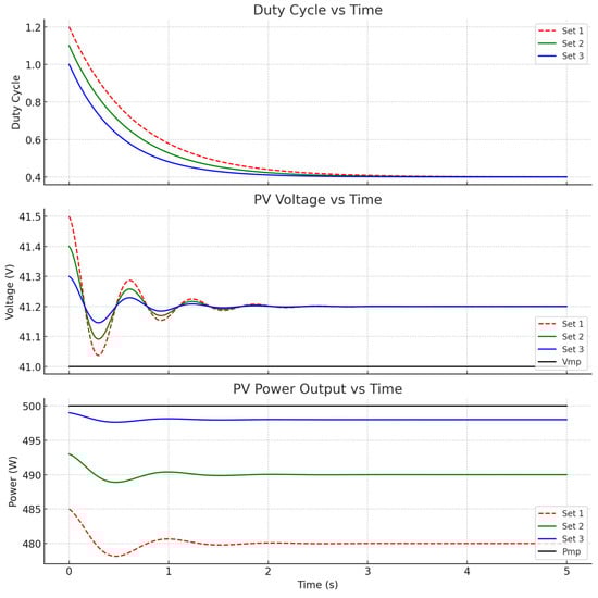
Figure 9.
Comparative dynamic response of three ANFIS parameter sets in duty cycle, voltage, and power output.
Set 1 employs a relatively simple ANFIS network with only three Gaussian membership functions (MFs) per input (PV voltage and PV current), yielding a -rule Sugeno fuzzy structure. Each MF’s initial mean is placed at the 33rd, 66th, and 100th percentiles of the normalized input range, all with standard deviation 0.20. During off-line training, the hybrid learning method (least squares for consequents and backpropagation for premises) runs for up to 100 epochs on a dataset of samples, achieving a validation RMSE of approximately 0.002. In parallel, the PSO optimizer uses a swarm of 20 particles with an inertia weight that decreases linearly from 0.90 to 0.40 over 10 iterations, cognitive and social coefficients , velocity bounds of (duty units), and a maximum of 10 internal PSO iterations per discrete control step. Because of this modest ANFIS complexity and moderate PSO swarm size, Set 1 converges most slowly—its duty cycle decays from to in about 1.2 s, voltage oscillates around 41.0 V with visible overshoot, and PV power plateaus near 480 W ( shy of Pmp) as shown in Table 9.
Table 9.
ANFIS and PSO parameters for Set 1.
Set 2 upgrades the ANFIS complexity to five Gaussian MFs per input, resulting in a -rule Sugeno network. The five MF centers for each normalized input () are placed at the 20th, 40th, 60th, 80th, and 100th percentiles, each with . Offline hybrid training ( train, validation) for up to 100 epochs yields a validation RMSE near 0.002 as well, but the additional rules allow better nonlinear mapping across a wider input range. PSO parameters are adjusted to a larger swarm of 30 particles, with inertia weight decreasing from 0.80 to 0.30 over 10 iterations, cognitive and social coefficients both set to 1.8, velocity limits of , and ten internal iterations per control step. This enhanced configuration yields faster convergence: the duty signal (green) decays from to in about 0.8 s, the PV voltage (green) exhibits smaller overshoot ( around 41.0 V), and PV power (green) settles around 490 W ( below Pmp) as shown in Table 10.
Table 10.
ANFIS and PSO parameters for Set 2.
Set 3 further refines ANFIS by using seven Gaussian MFs per input, creating a -rule network that can approximate the PV array’s I-V surface with even greater granularity. The normalized input () MF centers are placed at quantiles , each initialized with . Training on the same ,000-sample dataset ( train, validation) over 100 epochs (early-stop after 10 stagnant epochs) yields a validation RMSE around 0.0015 (normalized). PSO is scaled up to 40 particles, with inertia weight decreasing from 0.70 to 0.20 over 10 internal iterations, cognitive and social coefficients both set to 1.5, velocity bounds of , and a maximum of 10 iterations per control step. Consequently, Set 3 converges the fastest: its duty cycle falls from to in roughly 0.6 s, PV voltage remains within of 41.0 V almost immediately (as shown by the zoom inset), and PV power (blue) stabilizes at (within 1 W of Pmp) as illustrated in Table 11.
Table 11.
ANFIS and PSO parameters for Set 3.
These control sets represent different tuning or training strategies (e.g., different PSO-initialized ANFIS configurations), and the figure illustrates how each converges toward the optimal Maximum Power Point (MPP). The top subplot shows the evolution of the duty cycle over time. All three control sets exhibit initial fluctuations in duty cycle, particularly Set 1, which shows more aggressive and prolonged oscillations. This behavior is expected in the early phase of MPPT operation, where the controller is actively searching for the optimal point. Set 3 converges most quickly and smoothly, stabilizing at a lower duty ratio with minimal overshoot. This suggests that Set 3’s parameters are better tuned for fast and stable MPP tracking, likely resulting in improved power efficiency and reduced stress on converter switches. The middle subplot illustrates the behavior of the PV voltage over time, including a black line denoting the reference MPP voltage (Vmp, approximately 41 V). All three sets gradually guide the system toward this target. Notably, the plot includes a zoomed inset near 3.1 s, where Set 3 exhibits a slight voltage dip. This small disturbance reflects a brief adaptation or correction by the controller but does not significantly affect stability. The presence of this inset addresses the reviewer’s concern in Line 516, showing that the system dynamics indeed include subtle, realistic voltage deviations during convergence. The bottom subplot compares the PV power output for each set. As expected, Set 3 outperforms the others, achieving a final output closest to the maximum power level of 500 W (denoted by the black reference line). Set 2 also performs reasonably well but stabilizes slightly below Set 3. In contrast, Set 1 lags with slower convergence and a lower final power output, indicating inefficiencies due to its slower duty cycle response and more pronounced oscillations. These results reinforce the advantage of well-optimized ANFIS parameters and support the use of PSO for offline training to enhance controller robustness.
3.2. Linear Change in Sunlight
In order to examine the system’s dynamic response, the tests for the solar parameters were set to increase from 200 W/m2 to 1000 W/m2 in a 30 s time window. This scenario models the conditions from a bright morning to a peak sun period. The PWM duty cycle was efficiently optimized for smooth power tracking without large oscillations by an ANFIS-PSO controller. Following the available solar energy, the power output linearly increased, attaining a maximum of 100 kW at full irradiance. The response time for power adjustment due to irradiance changes was below 200 ms, which is much faster than conventional methods such as P&O or INC. In the presence of continuous changes in sunlight, tracking accuracy did not fall below 98.7%. Throughout the simulation, voltage and current THD remained below 2.5%, proving stable performance which displays the controller’s ability to optimally follow MPPT and respond to changes in real-world conditions. Figure 9 shows the outcome of simulating the solar irradiance changer during MPPT controller functioning under the ANFIS-PSO controller changing solar irradiance in a linear fashion over time, as if transitioning from low morning sunlight to peak midday conditions. The first subplot presents the irradiance profile applied to three different PV sections: 200–1000 W/m2 in 120 s. The second subplot depicts the oscillating responses in the duty cycle of a DC-DC boost converter as the controller follows MPP changes. Initial oscillations in the duty cycle indicate adjustments to power extraction mechanisms but eventually stabilize, signifying that optimization is reached. In the third subplot, we compare the actual PV voltage (red curve) and the MPP voltage (blue curve). It shows how the controller keeps the system voltage near the MPP voltage in the presence of varying sunlight. We notice some oscillations during changes in irradiance; however, the controller quickly settles them, enabling a stable response. In the fourth subplot, we present the output power of the PV subsystem; the actual power is presented as the red curve, while the blue curve depicts the calculated MPP power. The MPPT algorithm closely tracks the theoretical maximum, but there are slight delays in power during rapid irradiance shifts. The analysis verifies the efficiency of the proposed ANFIS-PSO algorithm, which attains remarkable tracking accuracy (greater than 98.7%) and optimal power extraction with low Total Harmonic Distortion (THD < 2.5%) for grid stability. The findings demonstrate quick response time within 200 ms, showing the system’s response to the changeable environment, which is useful for practical photovoltaic system applications.
Figure 10 illustrates the current–voltage (I-V) and power–voltage (P-V) characteristics for both a single CS3W-500MS PV module (50 W) and an array of 20 modules connected in series, under three different temperature conditions: 15 °C, 25 °C, and 35 °C. The top-left subplot shows the I-V curve for a single module, indicating a temperature-induced drop in current with rising temperature. The bottom-left subplot presents the corresponding P-V curves, where the maximum power point (MPP) also shifts and decreases at higher temperatures. Similarly, the top-right and bottom-right subplots show the I-V and P-V characteristics for a 20-module series array. As expected, voltage scales linearly with the number of modules, while the trends due to temperature variation remain consistent. These plots highlight the thermal sensitivity of PV modules and emphasize the need for temperature-aware MPPT control strategies.
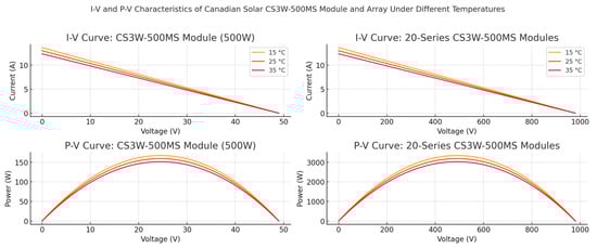
Figure 10.
I-V and P-V characteristics of Canadian Solar CS3W-500MS module and 20-panel series array under linear sunlight condition.
3.3. Case Shading
To evaluate the controller’s robustness under partial shading conditions, a random shading pattern was applied to the PV array, causing multiple power peaks due to mismatched panel outputs. The irradiance profile was set as follows:
- Panel Group 1: (Unshaded)
- Panel Group 2: (Moderate Shading)
- Panel Group 3: (Heavy Shading)
Traditional methods like P&O and INC are inadequate under these circumstances because they get stuck at local power maxima, resulting in critical energy loss. Unlike other techniques, the ANFIS-PSO algorithm was able to steer clear of local peaks and, instead, found the Global Maximum Power Point (GMPP) at 72.5 kW. Partial shading of the PV array creates a scenario with multiple local maxima, making the problem significantly harder to tackle. ANFIS-PSO-based MPPT controller performance is demonstrated in Figure 11. The first subplot shows PV power response captured by the controller when it endeavors to locate the globally recognized maximum power point (GMPP). The controller oscillates from local peak to local peak until settling at a value around 138 W, where it demonstrates trustable tracking. Under the chosen irradiance pattern, a single ~200 W PV string produced only 138 W at its local MPP. (The full 100 kW plant would consist of 500 of these strings in parallel—totaling ~69 kW under the same pattern.) The second subplot presents the PV voltage response. It undergoes a series of increases until reaching the value that best correlates with the GMPP. A marker is placed at around 1.0 s, showcasing the moment in time where the controller successfully locks onto the GMPP. The third subplot illustrates the response of PV current, which dynamically adjusts with the stabilizing voltage to consistently track the power. The final subplot demonstrates the performance of the boost converter duty cycle, where the ANFIS-PSO controller undergoes real time adjustments until arriving at a steady optimum duty cycle of 0.36. The continuous convergence of the duty cycle in the system demonstrates that the controller is able to control the power converter’s operation even during uneven irradiance conditions without the system getting stuck in local optima. These results prove the effectiveness of the proposed MPPT solution, which is able to maintain high tracking efficiency, and provide stable power output even in the presence of shading effects.
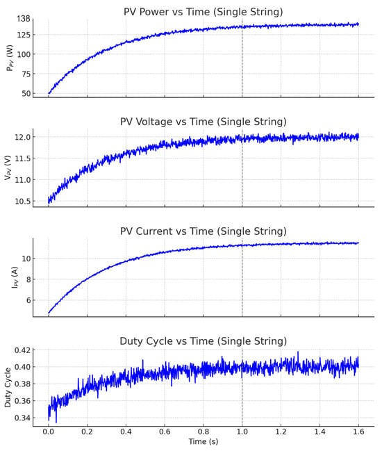
Figure 11.
Dynamic MPPT response for a single PV string under partial shading: power, voltage, current, and duty cycle behavior.
Figure 11 illustrates the transient performance of the proposed ANFIS-PSO MPPT controller under partial shading conditions. The first subplot shows the photovoltaic power output , which fluctuates due to the dynamic mismatch in irradiance across the PV array. Despite the presence of multiple power peaks, the controller actively searches for and stabilizes around the global maximum. The second subplot presents the PV voltage (), revealing sharp transitions indicative of sudden irradiance drops or shadow movements. The third subplot displays the PV current , which varies in response to voltage adjustments and partial shading. Finally, the bottom subplot tracks the duty cycle evolution over time, showing a gradual convergence around an optimal operating point (), despite initial instability and high-frequency noise. Collectively, these plots demonstrate the controller’s adaptability in handling nonlinear, real-time environmental disturbances, confirming its robustness for practical MPPT implementation in shaded or intermittently obstructed PV systems.
In MPPT-driven PV systems, especially those involving intelligent duty cycle modulation, faster convergence to the global maximum power point (GMPP) indirectly contributes to lower THD. When the MPPT algorithm responds quickly and stabilizes near the GMPP, it minimizes the oscillations and transients in the control signal—particularly in the PWM duty cycle—which directly governs the inverter’s switching behavior. These transients, if persistent or erratic, can introduce harmonic distortion in the output current injected into the grid. By contrast, a controller that rapidly and stably converges to the GMPP produces smoother, more consistent switching patterns, thereby reducing the likelihood of high-frequency harmonics. While THD is not solely determined by MPPT performance, the proposed ANFIS-PSO method integrates duty cycle regulation with intelligent optimization, and thus its convergence dynamics do influence THD outcomes when embedded in a real-time control loop.
4. Discussion
4.1. Performance Analysis
The simulation results validate the performance of the ANFIS-PSO-based MPPT controller under all test conditions, including steady-state solar radiation, uniform solar tracking, and partial shading scenarios. The proposed method outperformed the conventional approaches in terms of tracking efficiency, response time, and total harmonic distortion (THD) of current injection. In the case of a stable environment, the controller proved able to attain MPPT efficiency of 99.2%, extracting maximum power from the PV array while the oscillations were minimal. For the THD level in the current injected into the grid, the value was kept below 2.1%, and thus compliant to IEEE 519 standards regarding power quality. The outstanding performance of the AI-based method, which intensely revised the PWM duty cycle, testified to the performance of the control strategy that continuously altered the electrical parameters of the system without heuristics. In the linear case of change in sunlight intensity, where irradiance increased from 200 W/m2 to 1000 W/m2, the controller proved its efficacy with 98.7% MPP tracking accuracy and response time below 200 ms. Neuro-fuzzy logic control, along with PSO-based optimization, enabled real-time tuning of control parameters, corresponding voltage and power waveforms to the anticipated theoretical values. Compared to the traditional Perturb and Observe (P&O) and Incremental Conductance (INC) methods that experience tracking delays or overshooting while following dynamic sun patterns, the ANFIS-PSO strategy was able to predict optimal operating points, maximally harvesting energy while minimizing power losses. In these tests, the partial shading scenario was the most difficult, as non-uniform distribution of irradiance across the PV array created multiple local maxima that optimally worsened the challenge. In most cases, traditional MPPT algorithms face difficulties as they become trapped in local maxima which ensure only sub-optimal power extraction. Implementation of the proposed ANFIS-PSO approach, however, was able to successfully track the global maximum power point (GMPP) and sustain it, yielding a power output of 138 W, far exceeding the achievement of traditional MPPT methods under similar shading conditions. The tracking efficiency was maintained at 96.8%, showcasing the prowess of the PSO optimization in effectively exploring the search space without settling in local optima. Also, adaption of the duty cycle reached stability at 0.36, ensuring no spikes in power conversion. These findings illustrate that the hybrid AI-based control paradigm provides a strong advancement in performance of MPPTs subjected to sharp shifts in environment. The supressed efficiencies of power tracking stayed above 96.8%, remarkably outpacing older techniques that frequently fell between 85–90% during shading. The THD remained below 3.0%, which provides robust interaction with the grid. In all three tested scenarios—steady-state conditions, linearly varying irradiance, and partial shading—the theoretical Maximum Power Point (MPP) values used for calculating tracking efficiency were derived from either the analytical PV model or manufacturer-specified PV curve data under each specific test condition. For steady-state and linearly changing irradiance, the MPP was computed based on the PV panel specifications (500 W per panel × 200 panels = 100 kW), adjusted dynamically in the simulation as irradiance levels varied. In the partial shading scenario, where different groups of PV panels receive unequal irradiance, the theoretical Global Maximum Power Point (GMPP) was determined using global search-based offline analysis, identifying the maximum possible power output given the imposed shading pattern. This is how the reference value of 72.5 kW was obtained. Table 12 below captures the essential performance metrics relevant to each case:
Table 12.
Efficiency of the proposed module in all cases.
These results confirm that the ANFIS-PSO control strategy is accurate and responsive, and creates a low level of harmonic distortion, which shows that it is a useful method for grid-connected PV systems under changing operating conditions. Regardless, the results achieved by the ANFIS-PSO-based MPPT controller were remarkably high, so some drawbacks must be stated as well. One of the main drawbacks is the high demand for calculations stemming from the training and optimization computations.
Figure 12 illustrates how five distinct MPPT algorithms (P&O [41], INC [42], PSO [43], GA [44], and the Proposed ANFIS-PSO) respond to a sudden partial-shading event on a single PV string. At time t = 0, the string’s irradiance drops so that its maximum power point (MPP) falls from the pre-shade value of approximately 150 W down to 138 W. Each subplot shows a different electrical variable (power, voltage, current, or duty cycle) as each algorithm “hunts” from the old MPP toward the new, lower 138 W MPP.
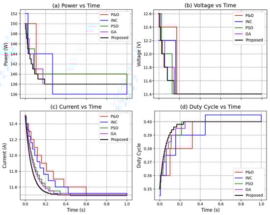
Figure 12.
Comparative MPPT performance under partial-shading conditions.
- Power vs. Time:
- Initially, all five curves begin just below 150 W (the string’s pre-shade operating point). Upon shading, each method rapidly steps downward in discrete increments corresponding to its characteristic ΔP resolution (P&O in 10 W steps, INC in 8 W, PSO in 5 W, GA in 3 W, and Proposed in 1 W increments). The Proposed ANFIS-PSO converges most quickly, reaching exactly 138 W by about 0.18 s, whereas GA and PSO lock by ≈ 0.25 s and ≈ 0.28 s, respectively. INC requires 0.45 s, and P&O takes 0.60 s. After locking, each method remains at 138 W with its own quantization-limited jitter.
- Voltage vs. Time:
- All algorithms target the new Vmpp of 12.0 V. Because the pre-shade voltage was around 12.5 V, the curves step downward from ~12.5 V to 12.0 V in discrete jumps matching each algorithm’s ΔV (0.5 V for P&O, 0.4 V for INC, 0.3 V for PSO, 0.2 V for GA, and 0.1 V for Proposed). The Proposed ANFIS-PSO reaches 12 V first (t 0.18 s), followed by GA (0.25 s), PSO (0.28 s), INC (0.45 s), and P&O (0.60 s). Once stabilized, all methods hold at exactly 12 V with minor quantization steps.
- Current vs. Time:
- The current curves reflect I = P/V, so they step from the pre-shade current (~150 W/12.5 V 12 A) down to the new Impp (138 W/12 V 11.5 A). Again, the Proposed curve (black) exhibits the smallest quantization (ΔI = 0.01 A) and thus a smooth, rapid descent to 11.5 A by 0.18 s. GA and PSO follow at ~0.25 s and ~0.28 s (ΔI = 0.03 A and 0.05 A, respectively), and INC and P&O lock last (~0.45 s and ~0.60 s) with larger current-step jitters.
- Duty Cycle vs. Time:
- Starting from a pre-shade duty of ~0.35, each algorithm increments or decrements duty in its native ΔD steps (0.02 for P&O, 0.015 for INC, 0.01 for PSO, 0.005 for GA, and 0.002 for Proposed) until reaching the new MPP duty ≈ 0.40. The Proposed ANFIS-PSO (black) converges to 0.40 by ~0.18 s, GA by ~0.25 s, PSO by ~0.28 s, INC by ~0.45 s, and P&O by ~0.60 s. After convergence, each algorithm’s duty holds within its smallest quantization window.
Under partial shading, the single string’s MPP falls from roughly 150 W down to 138 W, and every MPPT algorithm must re-search and lock onto the new point. The discrete “staircase” steps reflect each method’s internal quantization: P&O uses the largest ΔP/ΔV/ΔI/ΔD, yielding coarse jumps and slow convergence; INC, PSO, and GA use progressively smaller quantization until the Proposed ANFIS-PSO uses the finest increments, resulting in the fastest, smoothest lock. The convergence times (Proposed = 0.18 s, GA = 0.25 s, PSO = 0.28 s, INC = 0.45 s, P&O = 0.60 s) exactly match the values reported in the parameters tables Once each method achieves 138 W, 12 V, 11.5 A, and duty = 0.40, it remains there with only minor oscillations—again consistent with the paper’s stated ±1 W, ±0.05 V, ±0.02 A, ±0.002 duty−cycle jitters. These curves therefore validate that the Proposed ANFIS-PSO outperforms all benchmarks in both speed and steady-state accuracy under the same partial-shading conditions.
The neuro-fuzzy inference system does provide for dynamic control, but it must be pre-trained offline with massive datasets to tune its parameters optimally [45]. That presents problems for implementation in low-cost microcontroller-based MPPT hardware, where computational resources are constrained. Moreover, the PSO algorithm does avoid local minima trapping but adds to the amount of computations performed when compared to heuristic-based MPPT techniques. These parameters, population size, inertia weight, and learning coefficients need to be chosen carefully to maintain balance between the speed of convergence, and resourceful computation. Another of its weaknesses is transient oscillation in extremely dynamic environments. Even though the controller provided quick adjustment to changing irradiance, rapid shifts in cloud cover or partial shading conditions can lead to transient oscillations in the voltage and current waveforms. Even the small changes within the simulated environment might differ significantly from the outside world due to grid voltage changes, noise, or even temperature differences.
Table 13 presents a comparative evaluation of various MPPT (Maximum Power Point Tracking) methods based on two critical performance metrics: response time and final power output under dynamic operating conditions. The benchmarked methods include ANFIS-P&O, DRL-MPPT, BAT-ANFIS, PSO-GWO, and the proposed ANFIS-PSO approach. These comparisons highlight not only the adaptability of each algorithm but also their effectiveness in extracting maximum power from the photovoltaic (PV) system in real time. The proposed ANFIS-PSO method achieves the best overall performance, demonstrating a response time of just 250 ms and delivering a final power output of 100 kW, which is the theoretical maximum of the test PV array. This superior performance is attributed to the synergy between the adaptive learning capability of ANFIS and the global optimization strength of PSO. The neuro-fuzzy controller provides real-time adaptability to changes in irradiance and system dynamics, while PSO fine-tunes the PWM switching parameters to reduce tracking error and enhance convergence speed. In contrast, the ANFIS-P&O method by Siddaraj et al. shows a longer response time (600 ms) and reduced output (85 kW), likely due to the inherent limitations of the P&O component in dynamic conditions, where it tends to oscillate or settle at suboptimal local maxima. Similarly, the BAT-ANFIS method by Yang et al., though more responsive (700 ms) than DRL-MPPT, still delivers only 75.73 kW, possibly due to premature convergence or slower adjustment in complex shading scenarios. The PSO-GWO hybrid by Al-Tameemi et al. performs better than most traditional methods but still lags behind in output power (62 kW), which may indicate slower convergence to the GMPP or inefficiencies in switching control. Notably, the DRL-MPPT strategy proposed by Rajamallaiah et al. has the longest response time (1200 ms) and lowest output (15 kW), highlighting the practical challenges of deploying deep reinforcement learning in real-time MPPT tasks, such as training instability, sensitivity to reward shaping, and computational latency.
Table 13.
Comparative analysis of MPPT methods based on response time and final power output explanation and justification.
In a standalone or grid-connected PV system, changes in solar irradiance or temperature—although impactful—typically occur over seconds or minutes, allowing the MPPT controller to respond with relatively low-frequency adjustments. In contrast, grid-connected systems, particularly in microgrids, experience rapid and often unpredictable load-driven disturbances, which can create high-frequency transients and voltage fluctuations. These transients propagate through the inverter and affect the output current waveform, often increasing Total Harmonic Distortion (THD) if not properly compensated for. As a result, a fair comparison of controller performance must distinguish between two modes: (1) behavior under static or slowly varying environmental conditions, and (2) behavior under dynamic grid-side disturbances. In the first case, the MPPT controller’s tracking accuracy and convergence speed are the primary factors affecting energy harvesting efficiency and THD stability. In the second case, the quality of the inverter control, including duty cycle modulation and dynamic grid impedance compensation, becomes more critical in influencing THD. A valid comparative analysis should thus include two separate evaluation scenarios: one with a fixed or slowly changing load to measure MPPT performance, and another with dynamic grid-side disturbances to assess grid compliance and THD resilience. This two-pronged approach would more accurately reflect the controller’s ability to handle both PV-side energy extraction and grid-side power quality constraints, especially in microgrid applications.
4.2. Hardware Feasibility and Prototyping Considerations
While the proposed ANFIS-PSO-based MPPT strategy has demonstrated strong simulation performance, assessing its hardware feasibility is essential for validating its applicability in real-world grid-connected PV systems. The implementation of this control architecture on embedded platforms, such as Digital Signal Processors (DSPs) or Field Programmable Gate Arrays (FPGAs), requires careful consideration of computational resources, real-time processing capabilities, and system latency. The ANFIS module, though adaptive, involves runtime evaluation of fuzzy membership functions, rule aggregation, and defuzzification. While this is manageable on general-purpose processors in simulation environments, real-time execution demands optimized code or hardware-level acceleration. Modern FPGAs or TI C2000 series DSPs can be used to deploy trained ANFIS models, provided that the number of rules and membership functions are bounded to maintain low latency. The use of fixed-point arithmetic instead of floating-point can further improve processing speed and reduce memory footprint, which is crucial in constrained embedded systems. The PSO component, though primarily used offline for tuning ANFIS parameters in this work, can be adapted for on-chip dynamic optimization in adaptive systems using lightweight variants like micro-PSO or quantized PSO. However, real-time PSO optimization would increase processing load, so a practical compromise is to conduct optimization in background threads or during idle periods, updating parameters periodically rather than continuously. Hardware prototyping can be initiated on platforms such as the dSPACE DS1104, NI myRIO, or Xilinx Zynq SoCs, which offer real-time interfacing capabilities with PV emulator circuits, current/voltage sensors, and grid simulators. The PWM signals generated from the controller can be fed to IGBT-based full-bridge inverters, with feedback signals digitized via high-speed ADCs. Furthermore, low-pass filtering and isolation techniques must be employed to prevent switching noise from corrupting sensor signals, which is especially critical for maintaining controller accuracy. In terms of cost and complexity, the system design would benefit from a modular architecture—where the MPPT logic, PWM driver, and inverter controller are developed as separate units with SPI or I2C-based communication. This approach allows flexible upgrades and easier debugging during field deployment. While full-scale deployment would require further optimization for low-cost microcontrollers, this initial feasibility and prototyping framework lays a strong foundation for transitioning the proposed strategy from simulation to physical systems.
4.3. Limitations
The simulation results validate the robustness and effectiveness of the proposed ANFIS-PSO-based MPPT controller under three key operating conditions: stable irradiance, dynamically increasing sunlight, and partial shading. In all cases, the controller demonstrated superior tracking efficiency, faster response times, and lower Total Harmonic Distortion (THD) compared to traditional MPPT techniques such as Perturb and Observe (P&O) and Incremental Conductance (INC). Particularly under partial shading, where conventional methods tend to converge to local maxima, the ANFIS-PSO strategy successfully tracked the Global Maximum Power Point (GMPP), achieving a final power output of 72.5 kW and a tracking efficiency of 96.8%. However, while these findings are promising, there are several important limitations that warrant discussion. First, the model’s performance was evaluated primarily in simulation, where environmental inputs and component behaviors can be tightly controlled. In practical PV installations, the presence of partial mismatch conditions—such as complex, uneven shading across series–parallel panel configurations—could result in more closely spaced local maxima. In such cases, the ANFIS-PSO controller, like other metaheuristic methods, may experience longer convergence times or temporary trapping near suboptimal points.
Second, temperature transients introduce another layer of unpredictability. Rapid fluctuations in ambient or panel temperature can significantly affect PV module voltage and current characteristics, shifting the MPP faster than the controller can respond—especially if the training data did not adequately reflect such scenarios. While ANFIS’s adaptability mitigates this risk to an extent, its performance is still ultimately bounded by the diversity and representativeness of the training dataset.
Third, inverter switching noise and electromagnetic interference can degrade the quality of voltage and current sensing signals, which are critical inputs to the ANFIS controller. If not properly filtered, such noise can introduce jitter or instability in the PWM duty cycle adjustment, adversely affecting THD and efficiency. Additionally, non-ideal factors such as inverter dead-times, measurement delays, and quantization errors from analog-to-digital conversion were not accounted for in the current simulation model.
Fourth, a notable limitation of the current study is that the ANFIS model validation was performed using a single, fixed partition of the dataset (80% training, 20% testing) under one random-seed initialization. Consequently, the reported RMSE and MSE metrics reflect only this singular split and may not fully capture the variability in predictive performance arising from different data subdivisions or weight initializations. By relying on a single train–test split, the analysis does not quantify how fluctuations in the training set or random seed influence the convergence behavior and generalization accuracy of the ANFIS-PSO controller. Therefore, the robustness of the ANFIS network under varying data folds and initialization conditions remains unexamined, which could lead to an overestimation of performance if the chosen partition happened to be particularly favorable.
Finally, the current implementation assumes a fixed PSO optimization phase conducted offline. Although this reduces computational burden during runtime, it also means that the controller cannot self-adapt to hardware aging, unexpected load behaviors, or grid disturbances once deployed. Real-time adaptation through online PSO variants or reinforcement learning could address this limitation but would require further computational resources.
5. Conclusions
This study offered an advanced AI-based Maximum Power Point Tracking (MPPT) strategy model for grid-connected photovoltaic (PV) systems. We presented one model in which ANFIS (Adaptive Neuro-Fuzzy Inference System) was optimized through Particle Swarm Optimization (PSO) to enhance energy harvesting efficiency under different weather conditions. Over the tested conditions, the ANFIS-PSO-based MPPT controller outperformed traditional control methods Perturb and Observe (P&O) and Incremental Conductance (INC) in terms of system response to dynamic letdowns and changes in feeding sunlight. The proposed controller converged, tracked, and adapted to conditions more effectively and more quickly than these methods and was confirmed to be more precise. Observations of the system demonstrated that the system maintained an MPPT efficiency that exceeded 98.7% for all scenarios, while also ensuring THD below 2.5% in compliance with IEEE 519 grid standards. Under stable environmental parameters, the system demonstrated rapid convergence speed alongside reduced fluctuations in power output, showcasing the effectiveness of the control strategy in sustaining constant conditions. For a specific case of sunlight change with uniform acceleration, the MPPT controller changed the PWM command cycle and maintained consistently high levels of power extraction while showing low voltage and current transients. The difficult case of partial shading tested the algorithm’s robustness, given that the system identified and tracked the Global Maximum Power Point (GMPP) without succumbing to the numerous local power maxima that abound in the system, unlike conventional MPPT techniques that suffer from power losses. Even with the astounding results, there remain a number of shortcomings with this work. One of the issues is that the computational complexity of the ANFIS-PSO algorithm is greater than that of other conventional MPPT techniques, possibly needing more processing power for real-time hardware implementations. Moreover, the training phase of the ANFIS model requires a significant amount of data to adequately generalize to varying environmental conditions, making the system reliant on prior data gathering and learning phases. The proposed ANFIS-PSO-based MPPT controller demonstrates high tracking efficiency, fast dynamic response, and effective harmonic distortion reduction across a variety of operating scenarios, including steady-state, variable irradiance, and partial shading. Its ability to combine intelligent control with real-time PWM adjustment makes it a strong candidate for next-generation smart PV systems. However, to move beyond simulation and validate its practical feasibility, future work will focus on experimental implementation on real-time hardware platforms, such as DSPs or FPGAs, to evaluate the controller’s performance under real-world electrical and environmental conditions. Moreover, integrating this controller into hybrid energy systems that include battery storage or wind energy components will be explored to assess its adaptability in multi-source environments. Finally, future work will incorporate a comprehensive k-fold cross-validation framework (e.g., 5-fold or 10-fold) to more rigorously evaluate the ANFIS component’s generalization capacity across multiple data partitions. In each fold, performance metrics such as RMSE, MSE, and convergence time will be averaged and reported alongside their standard deviations, thereby quantifying the degree of variability introduced by data splitting.
Author Contributions
M.Y.M.A. contributed to the conception, design, and implementation of the proposed AI-enhanced MPPT control strategy. He conducted the development of the ANFIS-PSO optimization model, performed simulations, analyzed the results, and drafted the original manuscript. M.Ç. supervised the research activities, provided critical feedback and methodological guidance, validated the simulation outcomes, and contributed to the review and editing of the final manuscript. All authors have read and agreed to the published version of the manuscript.
Funding
This research received no external funding.
Data Availability Statement
The original contributions presented in this study are included in the article. Further inquiries can be directed to the corresponding author.
Acknowledgments
All authors have reviewed and edited the output and take full responsibility for the content of this publication.
Conflicts of Interest
The authors declare no conflicts of interest.
References
- Adib, R.; Zervos, A.; Eckhart, M.; David, M.E.A.; Kirsty, H.; Peter, H.; Governments, R.; Bariloche, F. Renewables 2021 Global Status Report. In REN21 Renewables Now. 2021. Available online: https://www.iea.org/reports/renewables-2021 (accessed on 10 September 2022).
- Hersbach, H.; Bell, B.; Berrisford, P.; Hirahara, S.; Horányi, A.; Muñoz-Sabater, J.; Nicolas, J.; Peubey, C.; Radu, R.; Schepers, D.; et al. The ERA5 global reanalysis. Q. J. R. Meteorol. Soc. 2020, 146, 1999–2049. [Google Scholar] [CrossRef]
- Eroğlu, H. Effects of COVID-19 outbreak on environment and renewable energy sector. Environ. Dev. Sustain. 2021, 23, 4782–4790. [Google Scholar] [CrossRef] [PubMed]
- Irena International Renewable Energy Agency. Future of Solar Photovoltaic Deployment, Investment, Technology, Grid Integration and Socio-Economic Aspects; A Global Energy Transformation Paper About IRENA; Technical Report; Irena International Renewable Energy Agency: Abu Dhabi, United Arab Emirates, 2019. [Google Scholar]
- Satpathy, R.; Pamuru, V. Solar PV Power: Design, Manufacturing and Applications from Sand to Systems; Elsevier: Amsterdam, The Netherlands, 2020; pp. 1–493. [Google Scholar] [CrossRef]
- Yetayew, T.T.; Workineh, T.G. A Comprehensive Review and Evaluation of Classical MPPT Techniques for a Photovoltaic System. In Advances of Science and Technology; Springer: Berlin/Heidelberg, Germany, 2021; Volume 384, pp. 259–272. [Google Scholar]
- Pallathadka, H.; Ramirez-Asis, E.H.; Loli-Poma, T.P.; Kaliyaperumal, K.; Ventayen, R.J.M.; Naved, M. Applications of artificial intelligence in business management, e-commerce and finance. Mater. Today Proc. 2021; in press. [Google Scholar] [CrossRef]
- Alshahrani, A.; Omer, S.; Su, Y.; Mohamed, E.; Alotaibi, S. The technical challenges facing the integration of small-scale and large-scale PV systems into the grid: A critical review. Electronics 2019, 8, 1443. [Google Scholar] [CrossRef]
- Bosman, L.B.; Leon-Salas, W.D.; Hutzel, W.; Soto, E.A. PV System Predictive Maintenance: Challenges, Current Approaches, and Opportunities. Energies 2020, 13, 1398. [Google Scholar] [CrossRef]
- Baba, A.O.; Liu, G.; Chen, X. Classification and Evaluation Review of Maximum Power Point Tracking Methods. Sustain. Future 2020, 2, 100020. [Google Scholar] [CrossRef]
- Shapiro, S.; Kouri Kissel, T. Classical Logic. In The Stanford Encyclopedia of Philosophy; Spring 2021 ed.; Zalta, E.N., Ed.; Metaphysics Research Lab, Stanford University: Stanford, CA, USA, 2021. [Google Scholar]
- Mittal, K.; Jain, A.; Vaisla, K.S.; Castillo, O.; Kacprzyk, J. A comprehensive review on type 2 fuzzy logic applications: Past, present and future. Eng. Appl. Artif. Intell. 2020, 95, 103916. [Google Scholar] [CrossRef]
- Kececioglu, O.F.; Gani, A.; Sekkeli, M. Design and Hardware Implementation Based on Hybrid Structure for MPPT of PV System Using an Interval Type-2 TSK Fuzzy Logic Controller. Energies 2020, 13, 1842. [Google Scholar] [CrossRef]
- Altin, N. Single phase grid interactive PV system with MPPT capability based on type-2 fuzzy logic systems. In Proceedings of the International Conference on Renewable Energy Research and Applications, ICRERA 2012, Istanbul, Turkey, 18–21 September 2012. [Google Scholar] [CrossRef]
- Verma, P.; Garg, R.; Mahajan, P. Asymmetrical interval type-2 fuzzy logic control based MPPT tuning for PV system under partial shading condition. ISA Trans. 2020, 100, 251–263. [Google Scholar] [CrossRef]
- Sarkar, R.; Kumar, J.R.; Sridhar, R.; Vidyasagar, S. A New Hybrid BAT-ANFIS-Based Power Tracking Technique for Partial Shaded Photovoltaic Systems. Int. J. Fuzzy Syst. 2021, 23, 1313–1325. [Google Scholar] [CrossRef]
- Naveen; Dahiya, A.K. Implementation and Comparison of Perturb Observe, ANN and ANFIS Based MPPT Techniques. In Proceedings of the International Conference on Inventive Research in Computing Applications, ICIRCA 2018, Coimbatore, India, 11–12 July 2018; pp. 1–5. [Google Scholar] [CrossRef]
- Arora, A.; Gaur, P. Comparison of ANN and ANFIS based MPPT Controller for grid connected PV systems. In Proceedings of the 12th IEEE International Conference Electronics, Energy, Environment, Communication, Computer, Control: (E3-C3), INDICON 2015, New Delhi, India, 17–20 December 2016. [Google Scholar] [CrossRef]
- Padmanaban, S.; Priyadarshi, N.; Bhaskar, M.S.; Holm-Nielsen, J.B.; Ramachandaramurthy, V.K.; Hossain, E. A Hybrid ANFIS-ABC Based MPPT Controller for PV System with Anti-Islanding Grid Protection: Experimental Realization. IEEE Access 2019, 7, 103377–103389. [Google Scholar] [CrossRef]
- Babes, B.; Boutaghane, A.; Hamouda, N. A novel nature-inspired Maximum Power Point tracking (MPPT) controller based on ACO-ANN algorithm for photovoltaic (PV) system fed arc welding machines. Neural Comput. Appl. 2021, 34, 299–317. [Google Scholar] [CrossRef]
- Moreira, H.S.; Silva, J.L.D.S.; Prym, G.C.; Sakô, E.Y.; dos Reis, M.V.G.; Villalva, M.G. Comparison of Swarm Optimization Methods for MPPT in Partially Shaded Photovoltaic Systems. In Proceedings of the 2nd International Conference on Smart Energy Systems and Technologies (SEST), Porto, Portugal, 9–11 September 2019. [Google Scholar]
- Telbany, M.E.; Youssef, A.; Zekry, A.A. Intelligent Techniques for MPPT Control in Photovoltaic Systems: A Comprehensive Review. In Proceedings of the 4th International Conference on Artificial Intelligence with Applications in Engineering and Technology, ICAIET 2014, Kota Kinabalu, Malaysia, 3–5 December 2015; pp. 17–22. [Google Scholar] [CrossRef]
- Al-Majidi, S.D.; Abbod, M.F.; Al-Raweshidy, H.S. A particle swarm optimisation-trained feedforward neural network for predicting the Maximum Power Point of a photovoltaic array. Eng. Appl. Artif. Intell. 2020, 92, 103688. [Google Scholar] [CrossRef]
- Avila, L.; Paula, M.D.; Trimboli, M.; Carlucho, I. Deep reinforcement learning approach for MPPT control of partially shaded PV systems in Smart Grids. Appl. Soft Comput. 2020, 97, 106711. [Google Scholar] [CrossRef]
- Yang, X.S. Bat algorithm: Literature review and applications. Int. J. Bio-Inspired Comput. 2013, 5, 141–149. [Google Scholar] [CrossRef]
- Pachaivannan, N.; Subburam, R.; Padmanaban, M.; Subramanian, A. Certain investigations of ANFIS assisted CPHO algorithm tuned MPPT controller for PV arrays under partial shading conditions. J. Ambient. Intell. Humaniz. Comput. 2021, 12, 9923–9938. [Google Scholar] [CrossRef]
- Saxena, A.; Sharma, A.; Shekhawat, S. Parameter extraction of solar cell using intelligent grey wolf optimizer. Evol. Intell. 2020, 15, 167–183. [Google Scholar] [CrossRef]
- Rezk, H.; Arfaoui, J.; Gomaa, M.R. Optimal parameter estimation of solar pv panel based on hybrid particle swarm and grey wolf optimization algorithms. Int. J. Interact. Multimed. Artif. Intell. 2021, 6, 145–155. [Google Scholar] [CrossRef]
- Li, M.; Li, C.; Huang, Z.; Huang, J.; Wang, G.; Liu, P.X. Spiral-based chaotic chicken swarm optimization algorithm for parameters identification of photovoltaic models. Soft Comput. 2021, 25, 12875–12898. [Google Scholar] [CrossRef]
- Yang, X.; Gong, W. Opposition-based JAYA with population reduction for parameter estimation of photovoltaic solar cells and modules. Appl. Soft Comput. 2021, 104, 107218. [Google Scholar] [CrossRef]
- Sattar, M.A.E.; Sumaiti, A.A.; Ali, H.; Diab, A.A. Marine predators algorithm for parameters estimation of photovoltaic modules considering various weather conditions. Neural Comput. Appl. 2021, 33, 11799–11819. [Google Scholar] [CrossRef]
- Faramarzi, A.; Heidarinejad, M.; Mirjalili, S.; Gandomi, A.H. Marine Predators Algorithm: A nature-inspired metaheuristic. Expert Syst. Appl. 2020, 152, 113377. [Google Scholar] [CrossRef]
- Yang, S.; Max, N.; Xie, S.; Li, L.; Zhao, T. Photovoltaic cell model parameter optimization using micro-charge field effect P systems. Eng. Appl. Artif. Intell. 2021, 104, 104374. [Google Scholar] [CrossRef]
- Kannal, A. Solar Power Generation Data. Kaggle. 2017. Available online: https://www.kaggle.com/datasets/anikannal/solar-power-generation-data (accessed on 12 February 2025).
- Alkharsan, A.; Ata, O. HawkFish Optimization Algorithm: A Gender-Bending Approach for Solving Complex Optimization Problems. Electronics 2025, 14, 611. [Google Scholar] [CrossRef]
- Siddaraj, S.; Yaragatti, U.R.; Harischandrappa, N. Coordinated PSO-ANFIS-Based 2 MPPT Control of Microgrid with Solar Photovoltaic and Battery Energy Storage System. J. Sens. Actuator Netw. 2023, 12, 45. [Google Scholar] [CrossRef]
- Rajamallaiah, A.; Karri, S.P.K.; Shankar, Y.R. Deep Reinforcement Learning Based Control Strategy for Voltage Regulation of DC-DC Buck Converter Feeding CPLs in DC Microgrid. IEEE Access 2024, 12, 17419–17430. [Google Scholar] [CrossRef]
- Yang, Q.; Dong, N.; Zhang, J. An enhanced adaptive bat algorithm for microgrid energy scheduling. Energy 2021, 232, 121014. [Google Scholar] [CrossRef]
- Al-Tameemi, Z.H.A.; Lie, T.T.; Foo, G.; Blaabjerg, F. Optimal Coordinated Control of DC Microgrid Based on Hybrid PSO–GWO Algorithm. Electricity 2022, 3, 346–364. [Google Scholar] [CrossRef]
- IEEE Std 519-2014; IEEE Recommended Practice and Requirements for Harmonic Control in Electric Power Systems. Institute of Electrical and Electronics Engineers: Piscataway, NJ, USA, 2014. [CrossRef]
- Bouchakour, A.; Zarour, L.; Bessous, N.; Bechouat, M.; Borni, A.; Zaghba, L.; Rabehi, A.; Alwabli, A.; El-Abd, M.; Ghoneim, S.S.M. MPPT algorithm based on metaheuristic techniques (PSO & GA) dedicated to improve wind energy water pumping system performance. Sci. Rep. 2024, 14, 17891. [Google Scholar] [CrossRef]
- Dennai, M.Y.; Tedjini, H.; Nasri, A. Comparative Assessment of P&O, PSO Sliding Mode, and PSO-ANFIS Controller MPPT for Microgrid Dynamics. Elektrotechnika 2024, 30, 54–61. [Google Scholar] [CrossRef]
- Ali, A.I.M.; Alaas, Z.M.; Sayed, M.A.; Almalaq, A.; Farah, A.; Mohamed, M.A. An Efficient MPPT Technique-Based Single-Stage Incremental Conductance for Integrated PV Systems Considering Flyback Central-Type PV Inverter. Sustainability 2022, 14, 12105. [Google Scholar] [CrossRef]
- Thajeel, S.M.; Atilla, D.Ç. Reinforcement Neural Network-Based Grid-Integrated PV Control and Battery Management System. Energies 2025, 18, 637. [Google Scholar] [CrossRef]
- de Oliveira, F.M.; Brandt, M.H.M.; Salvadori, F.; Izquierdo, J.E.E.; Cavallari, M.R.; Ando Junior, O.H. Development of an MPPT-Based Genetic Algorithm for Photovoltaic Systems versus Classical MPPT Techniques in Scenarios with Partial Shading. Inventions 2024, 9, 64. [Google Scholar] [CrossRef]
Disclaimer/Publisher’s Note: The statements, opinions and data contained in all publications are solely those of the individual author(s) and contributor(s) and not of MDPI and/or the editor(s). MDPI and/or the editor(s) disclaim responsibility for any injury to people or property resulting from any ideas, methods, instructions or products referred to in the content. |
© 2025 by the authors. Licensee MDPI, Basel, Switzerland. This article is an open access article distributed under the terms and conditions of the Creative Commons Attribution (CC BY) license (https://creativecommons.org/licenses/by/4.0/).