1. Introduction
The line-commutated converter (LCC)-based high-voltage direct current (HVDC) transmission system employs semi-controlled power electronic devices as commutation valves. This technology has the advantages of rapid active power control, low losses and a low cost [
1]. Thus, it is well-suited for long-distance and high-capacity power transmission applications. However, the thyristors in the LCC lack a self-turn-off capability, so the LCC needs to be connected to a strong AC system with a sufficient short-circuit capacity [
2]. Also, the LCC-based HVDC (LCC-HVDC) system requires approximately 50–60% of the rated DC power during operation and has an inherent limitation of commutation failure (CF) [
3].
Due to the above limitations of the LCC, researchers focused their efforts on developing next-generation HVDC transmission technologies. In the 1990s, the voltage source converter (VSC)-based HVDC (VSC-HVDC) technology [
4] and the capacitor-commutated converter (CCC)-based HVDC (CCC-HVDC) technology [
5,
6] emerged and evolved concurrently. Both technologies aim to address the inability of the LCC to operate reliably when connecting to the extremely weak AC system.
The CCC technology was proposed by Buseman in 1954 [
7]. The CCC topology is formed as a conventional LCC modified with a series capacitor between the converter transformer and the thyristor valves in each phase. The series-connected capacitor, which is called the commutation capacitor, can generate an additional commutation voltage to assist the commutation process. ABB started researching CCC technology in 1995 [
8], recognizing that it could be extended to practical HVDC transmission engineering applications [
9]. There are three CCC-HVDC projects in the world, including the Garabi Project in Brazil in 2000 [
10], the Rapid City Project in the U.S. in 2003 [
11] and the Rio Madeira Project in Brazil in 2013 [
12].
The measures to mitigate the possibility of the CF in an LCC-HVDC system primarily involve three technical routes [
13,
14,
15]: the employment of the additional auxiliary equipment, the optimization of the control systems and the modification of the converter topologies. The three technical routes for the CF mitigation are compared in
Table 1.
In terms of employing the additional auxiliary equipment, the reactive power compensation devices can be installed to support the AC voltage and thereby suppress the CF [
16]. These devices typically include AC filters, a static var compensator (SVC), a static synchronous compensator (STATCOM), a synchronous compensator, etc. Additionally, ref. [
17] has demonstrated that the unified power flow controller (UPFC) and the dynamic voltage regulators (DVR) can reduce the risk of the CF through the DC power flow control. The UPFC requires a smaller capacity than the STATCOM to achieve the equivalent CF suppression effect under the same condition of the short-circuit ratio and the fault severity.
In terms of mitigating the CF based on the control system, optimization can be categorized into the advanced firing angle control and the voltage-dependent current order limiter (VDCOL) control. The advanced firing angle control [
18] is implemented when the detection of an AC fault indicates a potential risk of the CF. In such cases, the firing angle of the inverter is advanced to ensure a larger commutation margin. The literature [
19,
20] has investigated techniques for detecting the AC faults and optimizing the control parameters for CF prevention. However, the advanced firing approach increases the reactive power consumption of the inverter, which is detrimental to the recovery of the AC voltage after the fault. The widely adopted VDCOL control [
21] in industrial applications involves reducing the DC current reference value to reduce the commutation fault current after detecting a decrease in the AC voltage, thereby mitigating the risk of CF.
In terms of modifying the converter topologies [
22], the most notable technical route is the use of the CCC. Compared to the conventional LCC, the CCC technology can reduce the reactive power compensation capacity. Also, it can reduce the probability of the initial CF due to the insertion of commutation capacitors. However, it may experience continuous CF because of the uncontrolled charging process of the commutation capacitors after the initial CF.
To enhance the controllability of the commutation capacitors in the CCC, ref. [
23] introduced an approach utilizing the active capacitors by connecting a three-phase voltage source PWM converter in series to emulate the effect of the commutation capacitors. In [
24], the authors proposed a hybrid active and passive CCC, where a low-power three-phase VSC is connected between the commutation capacitors and the thyristor valves. The series-connected VSC acts as an auxiliary commutation capacitor, actively increasing the equivalent capacitance value of the circuit to mitigate the continuous CF in the CCC. To effectively reduce the losses associated with frequently switching insulated gate bipolar transistors (IGBTs) in the HVDC system, ref. [
25] proposed a method utilizing thyristor-based controlled capacitors combined with a system-coordinated control strategy to mitigate the probability of the CF. Based on this, ref. [
26] demonstrated the feasibility of controlling the reactive power and the AC voltage of the inverter by employing series-connected controlled capacitors, thereby replacing the AC filter configuration [
27,
28]. In [
29], the authors introduced a novel topology named the enhanced capacitor-commutated converter (ECCC) with anti-parallel thyristors-based full-bridge submodules. By embedding these submodules into the CCC and using reasonable switching control strategies, the risk of CF can be effectively reduced. In [
30], the authors proposed an improved coordinated control strategy for the ECCC. It can ignore the effect of fault detection delays and accelerate the commutation process to reduce the possibility of CF. In [
31], the IGBT-based full-bridge submodules are series-connected to the valve side of the converter transformer. By controlling the connection and disconnection of the commutation capacitors, this topology aims to eliminate CFs under severe conditions. In [
32], the authors presented a hybrid HVDC system topology, where each converter station comprises a series-connected CCC and a two-level VSC, and a nonlinear state-space averaging model analysis was proposed to study the system characteristics. In [
33], the authors introduced a novel controllable line-commutated converter (CLCC) topology with a controlled shut-off capability, which can effectively resolve the issue of CF and provide short-term power support to the AC system. This topology was experimentally validated in the Ge’nan Project. In [
34], the authors proposed a multi-source adaptive LCC named SLCC, in which a three-phase VSC was connected to the valve side of the converter transformer. The SLCC is capable of supporting the commutation voltage during the transient process and reducing the risk of CFs. Since the commutation capacitor in the CCC is uncontrollable, the charging and discharging states depend on the current flowing through the commutation capacitor. After the first CF, the AC bus voltage drop at the inverter side may increase the probability of another CF during the recovery process. In severe cases, it may lead to the CCC losing its self-recovery capability. However, the solutions for the continuous CF in the CCC are not systematically described in the existing literature. Thus, it is necessary to propose a novel solution to improve the continuous CF in the CCC.
To address this issue, this paper proposes a novel topology named the submodule-cascaded STATCOM-based CCC (SCCC). The SCCC is formed by paralleling a submodule-cascaded STATCOM (SC-STATCOM) on the valve side of the converter transformer in the CCC. Compared to the CCC, the SCCC can replace the AC filters and the reactive power compensation devices. It can also improve the AC fault transient performance by enhancing the reactive power support during the transient process, thereby reducing the risk of CFs.
The CF study for the SCCC has two main aspects. Firstly, it investigates whether the SCCC has a better immunity to the initial CF and the better fault recovery characteristics compared to the CCC. Secondly, it explores whether the SCCC can mitigate the technical defect of the continuous CF in the CCC.
The organization of this paper is as follows. In
Section 2, the topology structure, the mathematical model and the control strategy for the reactive power compensation and the active filtering of the SC-STATCOM are introduced. In
Section 3, the mechanisms through which the continuous CFs can occur in the CCC are explained. By comparing the power transmission curves of the LCC, the CCC and the SCCC during the steady-state operation, the maximum power curves of the SCCC topology under the different SCR and the capacities are presented. By analyzing the reactive power at different apparent extinction angles, the feasibility of the SCCC fully replacing the reactive power compensation devices by connecting to SC-STATCOM is demonstrated. In
Section 4, a two-terminal HVDC transmission model is built in PSCAD/EMTDC, where three converters are adopted at the inverter side, respectively. The transient characteristics of the three cases under the non-severe three-phase grounding faults and the severe single-phase grounding faults in the AC system are analyzed. The commutation failure immunity index (CFII) and the commutation failure probability index (CFPI) are compared among the three cases. Finally, conclusions are drawn in
Section 5.
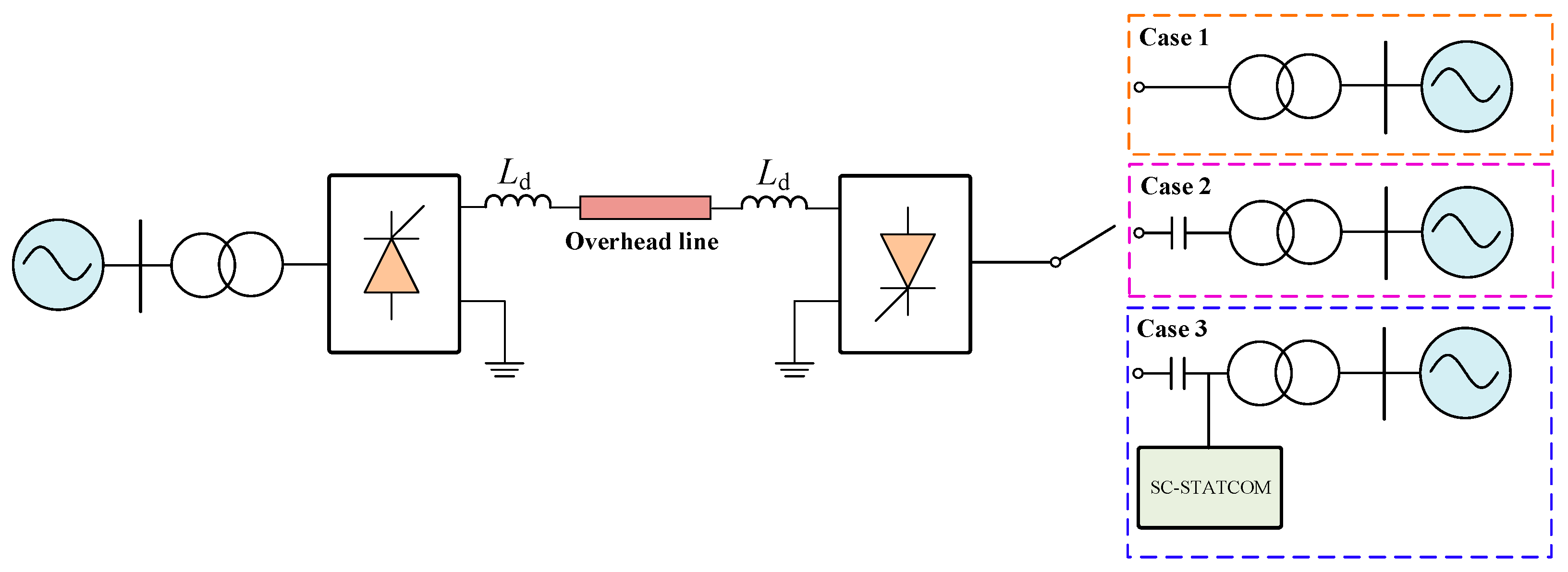
3. The Novel SCCC Technology
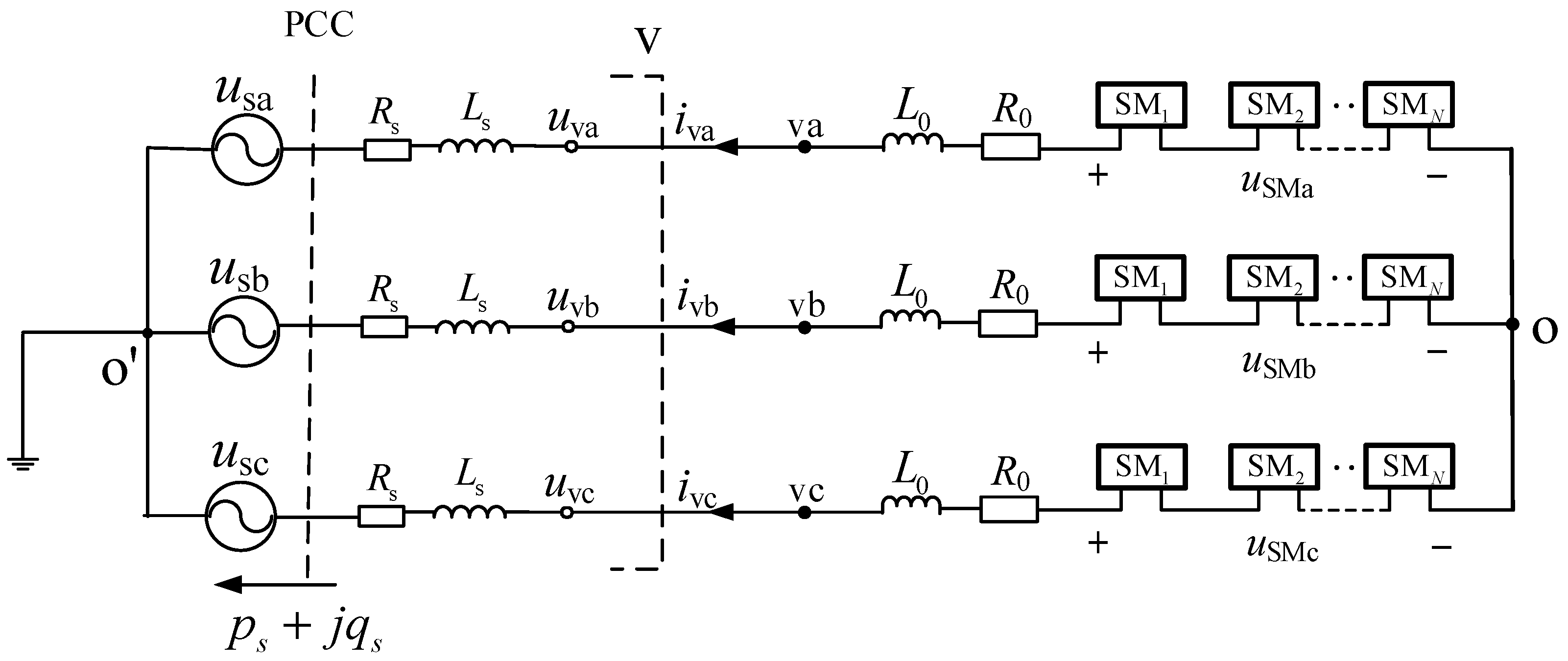
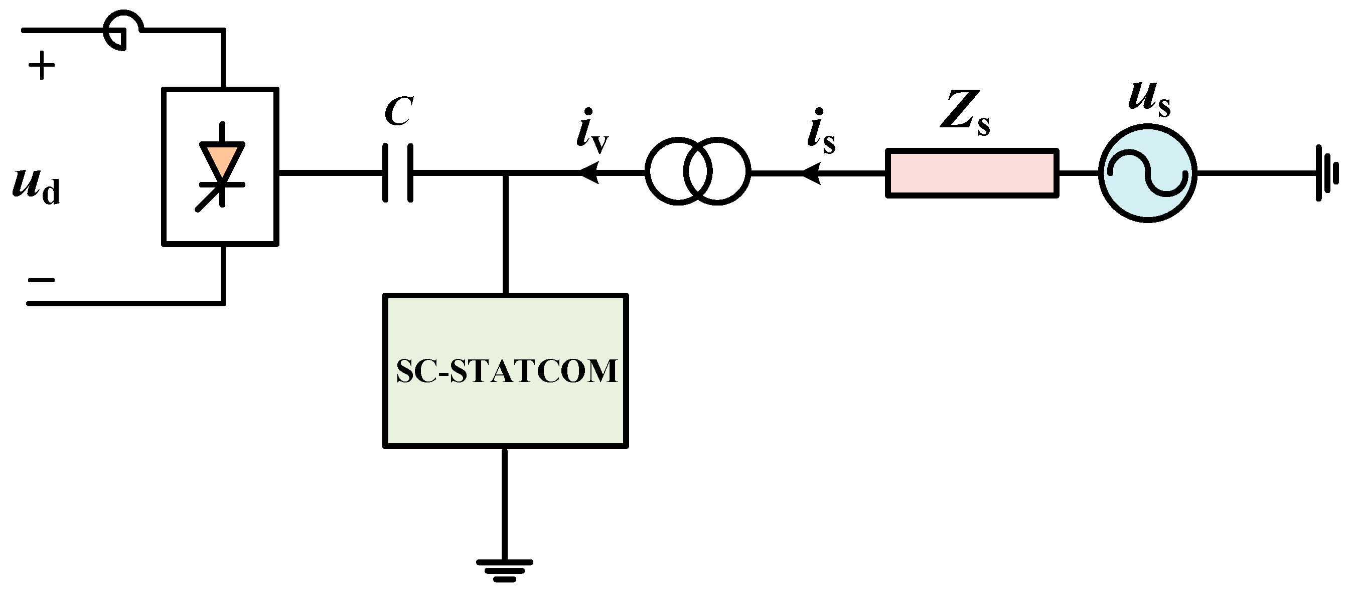
This section proposes a novel converter technology that integrates a SC-STATCOM into the valve side of the converter transformer in the CCC, forming the SCCC topology. The structure is shown in
Figure 5.
us is the voltage of the AC grid.
Zs is the equivalent impedance of the AC grid.
is is the current of the AC grid.
iv is the valve side current of the converter transformer.
The traditional LCC topology acts as a current source, relying on the AC system for commutation at the inverter side. Thus, its dynamic characteristics are poor and its disturbance rejection capability is weak. While the CCC topology reduces the reactive power compensation requirements and mitigates the probability of the initial CF, the subsequent CF may still occur due to the uncontrollable charging of the commutation capacitors after the initial CF. The proposed SCCC topology, formed by connecting the SC-STATCOM in parallel with the CCC at the valve side of the converter transformer, represents a novel hybrid topology combining the current-source and voltage-source characteristics.
The SCCC can not only replace the AC filters and the reactive power compensation devices, but also enhance the system immunity to commutation failures. There are two factors that influence the cost of the SCCC technology compared to the CCC. On the one hand, the equipment cost of the AC filters and the reactive power compensation devices can be saved. On the other hand, the insertion of the SC-STATCOM will increase the cost. In engineering application, the adoption of the SC-STATCOM will increase the complexity of the SCCC. However, due to the maturity of the recent modular multi-level technology, the modularization and the control strategy of the SC-STATCOM can be easily achieved in engineering.
The main features of the SCCC are as follows:
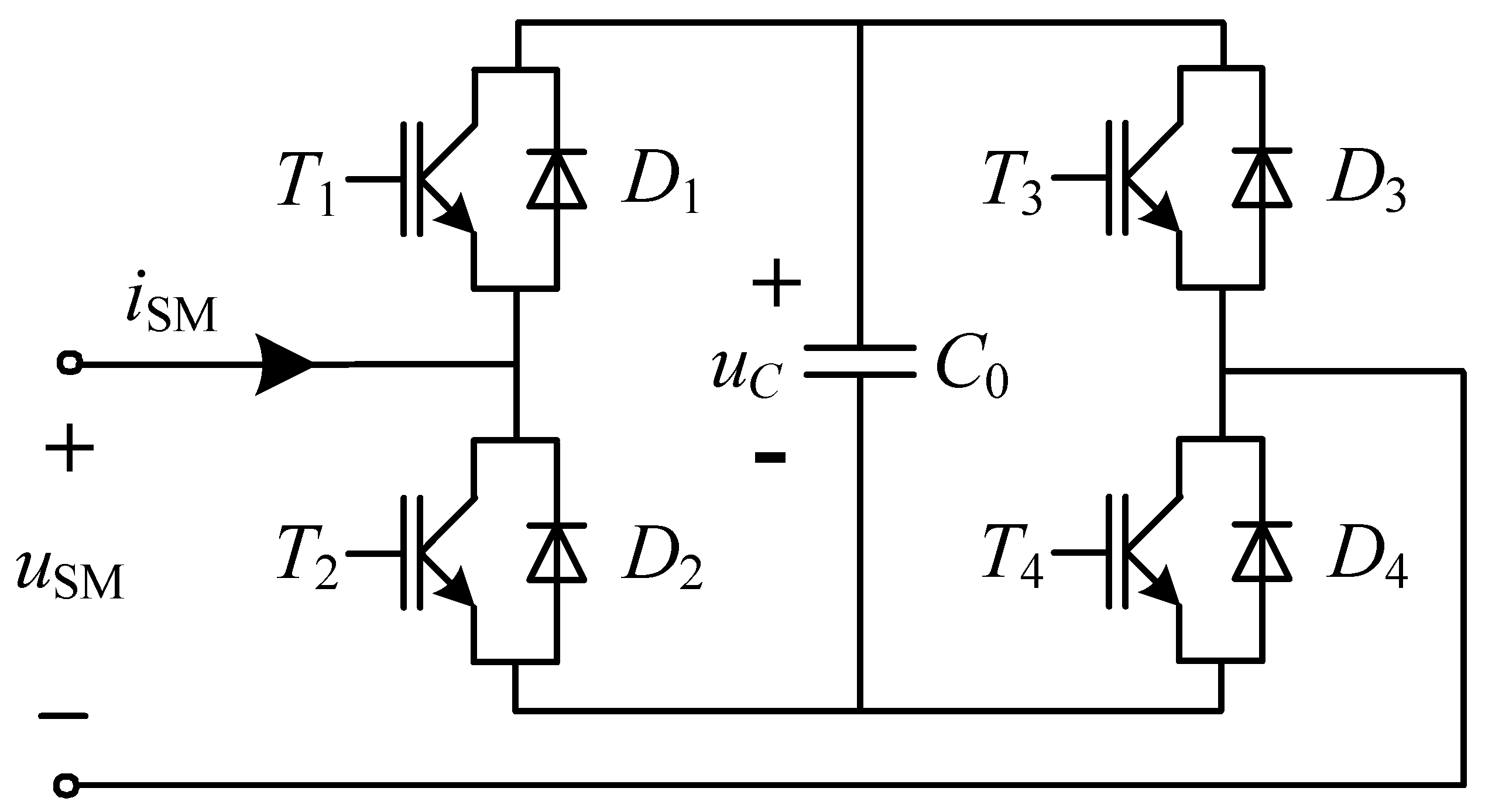
(1) Modular Multilevel Technology: The flexible scalability of submodule cascading enables adaptation to the capacity requirements of the HVDC transmission systems, offering high reliability and low losses.
(2) Active Filtering Function: It replaces conventional AC filters, significantly reducing the building area of the converter station.
(3) Dynamic Reactive Power Compensation: It provides flexible dynamic reactive power regulation.
(4) Enhanced Commutation Failure Immunity: It reduces the probability of the CFs during the AC faults, thus supporting the AC voltage and improving the waveform during the fault recovery process.
3.1. Technical Defect of CCC
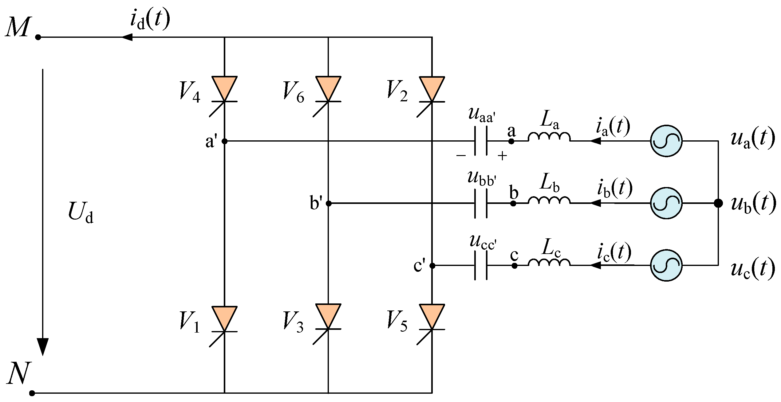
The schematic diagram of the CCC at the inverter side is shown in
Figure 6.
V1~
V6 represent the thyristor valves.
ua,
ub and
uc are the valve side voltages of the converter transformer.
uaa′,
ubb′ and
ucc′ are the terminal voltages of the commutation capacitors connected in series between the converter transformer and the thyristor valves, with their positive polarity directions shown in
Figure 6.
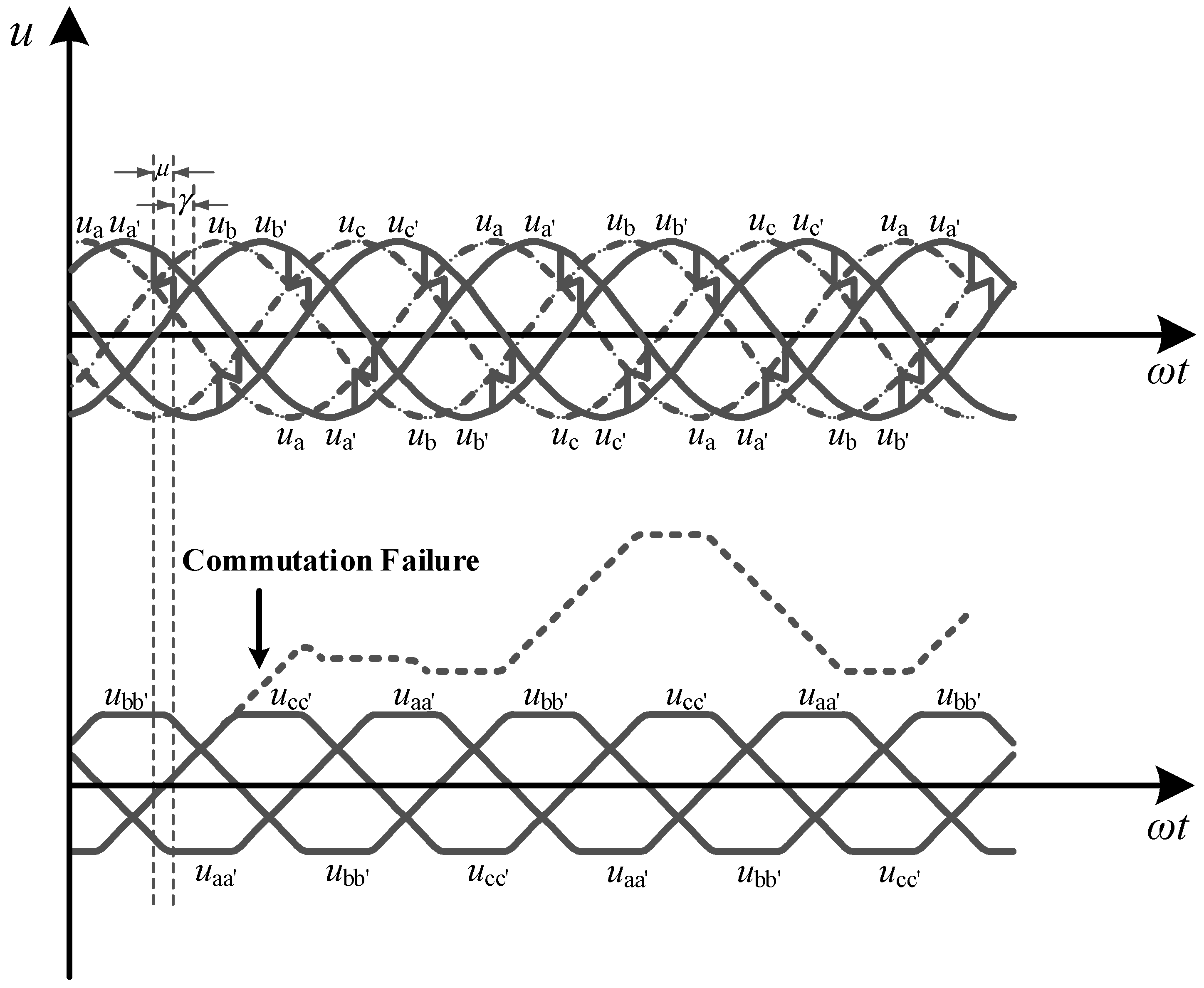
Figure 7 illustrates the waveforms of the AC voltages and commutation capacitor terminal voltages. The dashed lines represent the phase voltage waveforms on the valve side of the converter transformer, while the solid lines represent the actual commutation voltage waveforms across the thyristor valves. As observed from the AC phase voltage waveforms, the commutation capacitors introduce an additional voltage, causing the commutation voltage to lag behind the valve side voltage of the converter transformer by an angle. Consequently, the zero-crossing point of the actual commutation voltage across the thyristor valves lags behind that of the AC line voltage by the same angle. Even if the apparent extinction angle
γapp is smaller than the critical extinction angle
γmin, the actual extinction angle
γreal is still sufficient to ensure the successful commutation process. The phase lag and amplitude increase of the actual commutation voltage due to the additional capacitor voltage enable a significant reduction for the apparent extinction angle
γapp, thereby reducing the probability of the initial CF at the inverter side and reducing the reactive power absorption by the converter.
After a CF occurs in the CCC due to an AC fault at the inverter side, several thyristor valves are not turned off properly. The commutation capacitor connected to those thyristor valves continues to charge, leading to overvoltage and potentially triggering the subsequent CF during the fault recovery process. The process of the continuous CF is analyzed in detail below using the c-phase as an example, where dashed lines represent the waveform of the c-phase commutation capacitor voltage ucc′ after the initial CF.
Assume the initial CF occurs during the commutation process from valve V5 to V1, where V5 fails to turn off and remains conducting. Consequently, the c-phase commutation capacitor voltage ucc′ charges continuously to the overvoltage state. During the commutation process from V6 to V2, the c-phase commutation capacitor discharges, reducing ucc′. However, due to the limited discharge time, the polarity of the c-phase commutation capacitor remains positive without reversal. During the commutation process from V2 to V4, the positive voltage of the c-phase commutation capacitor lowers the potential at point c′, impeding the turn-off of V2. Subsequently, during the commutation process from V3 to V5, the c-phase commutation capacitor continues to charge, increasing ucc′ and impeding the turn-on of V5. From the above analysis, after the initial CF causes abnormal overvoltage charging in the commutation capacitor, the unipolar overvoltage will impede the turn-off and turn-on process of the upper and lower valves connected to the commutation capacitor during the next commutation process. Thus, the duration of the commutation process will be longer and the commutation margin will be reduced. The abnormal operating state of the thyristor valves may lead to the subsequent CF during the fault recovery process, even resulting in multiple CFs and ultimately damaging the self-recovery capability of the converter.
As the commutation capacitance decreases, its capacitive effect becomes more noteworthy. However, the disturbances during the fault recovery process and the asymmetric charging effect on the commutation capacitors become significant, leading to the greater possibility of continuous CF. It is the technical defect of the CCC technology.
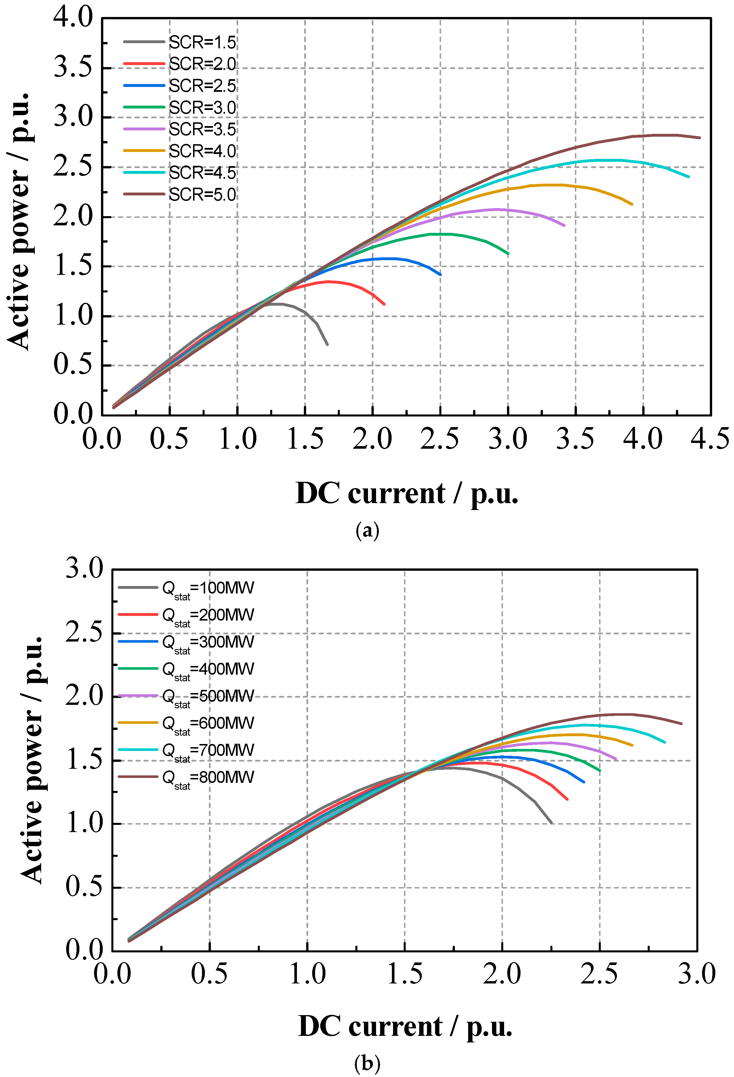
3.2. Analysis of Power Transmission Characteristics
Firstly, several fundamental concepts are introduced. The maximum power curve (MPC) represents the curve describing the relationship between the active power transmitted by the converter and the DC current without employing special AC voltage control strategies. The maximum available power (MAP) represents the maximum transmissible power of the converter station, corresponding to the peak value of the MPC curve, which characterizes the static stability limit of the AC system. The short-circuit ratio (SCR) represents the strength of the AC system, defined as follows:
where
Sac is the short circuit capacity of the AC bus.
PdN is the rated DC power.
UN is the rated AC voltage.
Z is the equivalent impedance of the AC system.
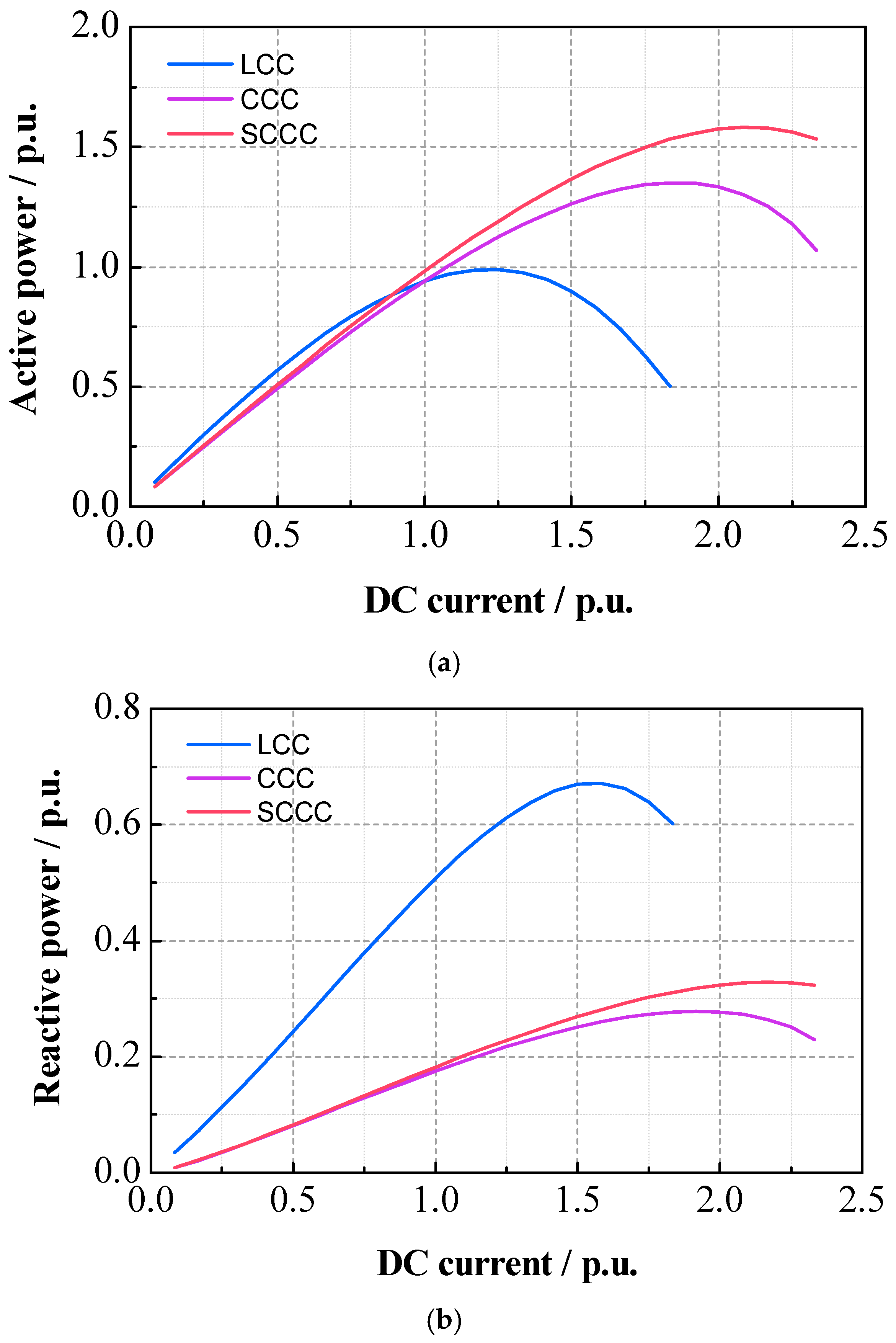
A ±500 kV/3000 MW HVDC transmission system with a SC-STATCOM is given. The SCR of the AC system is 2.5. The reactive power injected by the SC-STATCOM to the AC system
Qstat is 400 MW. The steady-state operating characteristics of the three converter topologies (LCC, CCC and SCCC) are compared in
Figure 8.
From
Figure 8, under the identical SCR condition, the active power decline of the CCC with the increasing DC current is smaller than that of the LCC, indicating the improved MAP characteristics. The SCCC technology further enhances the MAP characteristics by increasing the DC current stability limit at the MAP point, thereby enhancing the static stability limit. At the rated DC current, the reactive power requirement of the LCC is approximately 50% of the rated power. Meanwhile, the reactive power requirement of the CCC and the SCCC is approximately 18% due to the higher power factors.
For the SCCC topology, two MPC curve investigations are conducted: (1) Fixed
Qstat = 400 MW, the SCR increased from 1.5 p.u. to 5.0 p.u. with the step of 0.5 p.u. (2) Fixed SCR = 2.5, the
Qstat increased from 100 MW to 800 MW with the step of 100 MW. The results are shown in
Figure 9.
As can be seen from the figure, increasing the SCR or increasing the capacity of the SC-STATCOM can shift the MPC curve upward and to the right, and the corresponding MAP also increases. This implies an enhanced active power transmission capability and improved static stability limits at higher DC currents.
In summary, for the CCC and the SCCC operating at the same MAP value, the SCCC requires a smaller SCR. This indicates that the SC-STATCOM significantly strengthens the AC system by increasing the apparent SCR at the inverter side. Moreover, the apparent SCR increases with higher Qstat.
3.3. Reactive Power Compensation Capacity Analysis
Since the SC-STATCOM can replace the conventional reactive power compensation devices, its capacity selection needs to be investigated. The ±500 kV/3000 MW HVDC transmission system model is built in the simulation software, with an SCR of 2.5 and a commutation capacitance of 129.75 μF. Simulations are conducted under different apparent extinction angles
γapp to determine the SC-STATCOM output reactive power
Qstat, the reactive power absorbed by the converter
QCCC, the reactive power provided by commutation capacitors
QC and the reactive power provided by the AC system
Qac. The results are summarized in
Table 2.
It can be seen that QC remains constant due to the fixed capacitance and the terminal voltage magnitude. The CCC initially exports the reactive power and then absorbs it, with the absorbed reactive power increasing as γapp rises. Consequently, Qstat also increases as γapp rises.
The CCC requires 227 MVar of the reactive power at the rated operating condition (γapp = 1.57°). It consumes approximately 15% of the rated DC power (1500 MW for single pole), which is significantly lower than the 50–60% reactive demand of the LCC under equivalent conditions. Considering the additional reactive power requirement during the AC fault transient process, the practical SC-STATCOM capacity should be set to 1.5–2 times the steady-state reactive power demand, i.e., 23–30% of the rated DC power.
Notably, the LCC typically uses the extinction angle of 17° to ensure the thyristor turn-off margin. In the CCC or the SCCC systems, the commutation margin is related to the actual extinction angle γreal, whereas the reactive power is related to the apparent extinction angle γapp. A smaller γapp still satisfies the thyristor safety requirements. Thus, the SCCC-based HVDC system can operate with a reduced γapp and a smaller SC-STATCOM capacity.
In summary, the SCCC topology can fully replace conventional reactive compensation devices by the SC-STATCOM, with its capacity determined by the CCC’s reactive power demand.
4. Simulation Analysis
Three two-terminal HVDC transmission systems with different converter configurations are developed in PSCAD/EMTDC. Case 1 is a conventional ±500 kV/3000 MW HVDC transmission system with an LCC at the inverter side. Case 2 is a modified system based on case 1 with a CCC at the inverter side. Case 3 is modified system based on case 1 with a SC-STATCOM at the inverter side.
The monopolar topology schematics of the three cases are shown in
Figure 10.
4.1. System Parameters
Based on the main circuit parameter calculation of the CCC in [
1], the system parameters for case 1 and case 2 are listed in
Table 3.
Case 3 shares the same rectifier and inverter parameter design as case 2 but integrates the SC-STATCOM at the valve side of the converter transformer, replacing the reactive compensation devices and AC filters. The parameters of the SC-STATCOM are listed in
Table 4. To ensure the transient performance is comparable, the extinction angles for both the CCC and the SCCC are set to 17° and the SC-STATCOM rated capacity is set as 1000 MVA.
4.2. Transient Characteristic Analysis
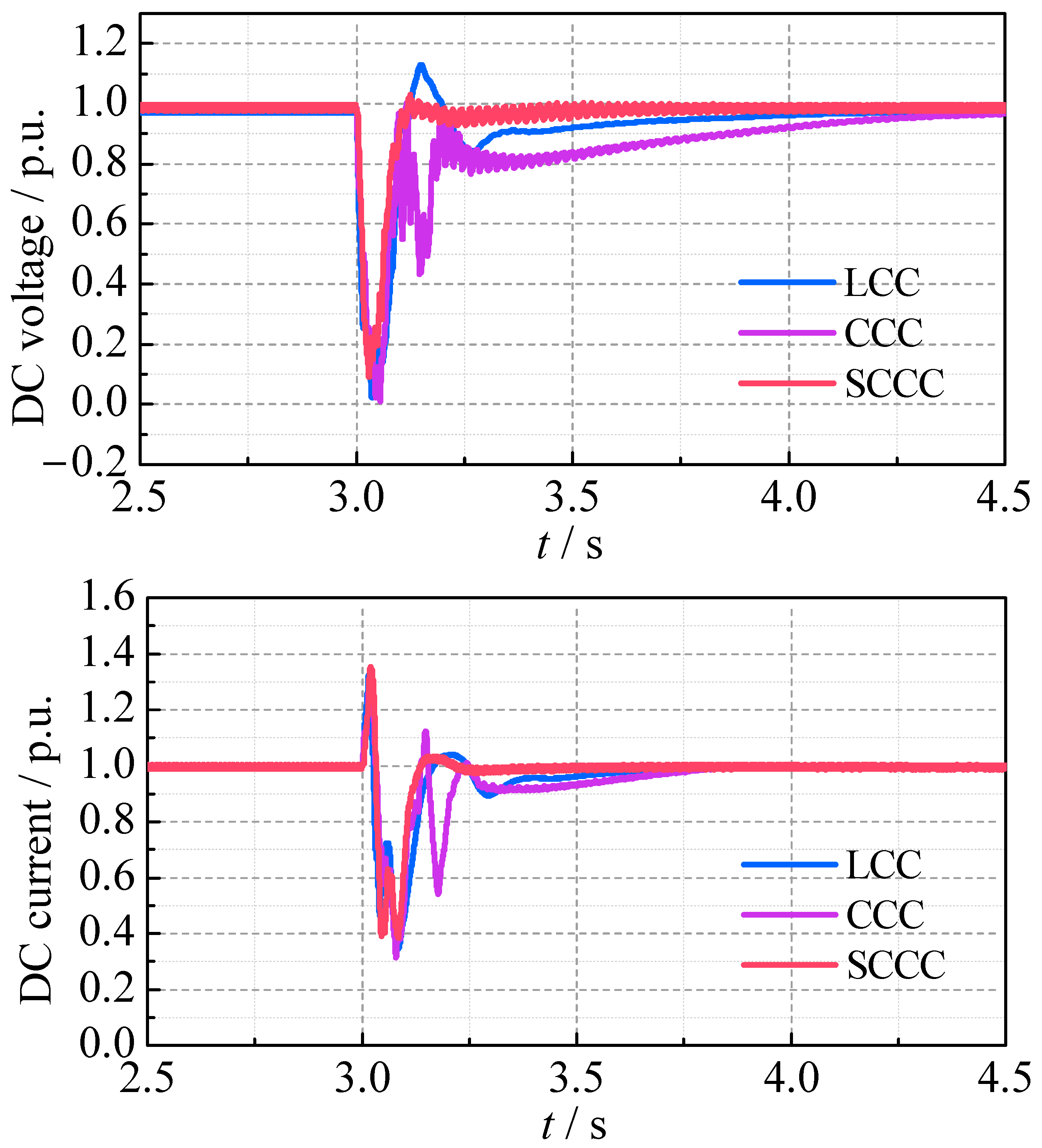
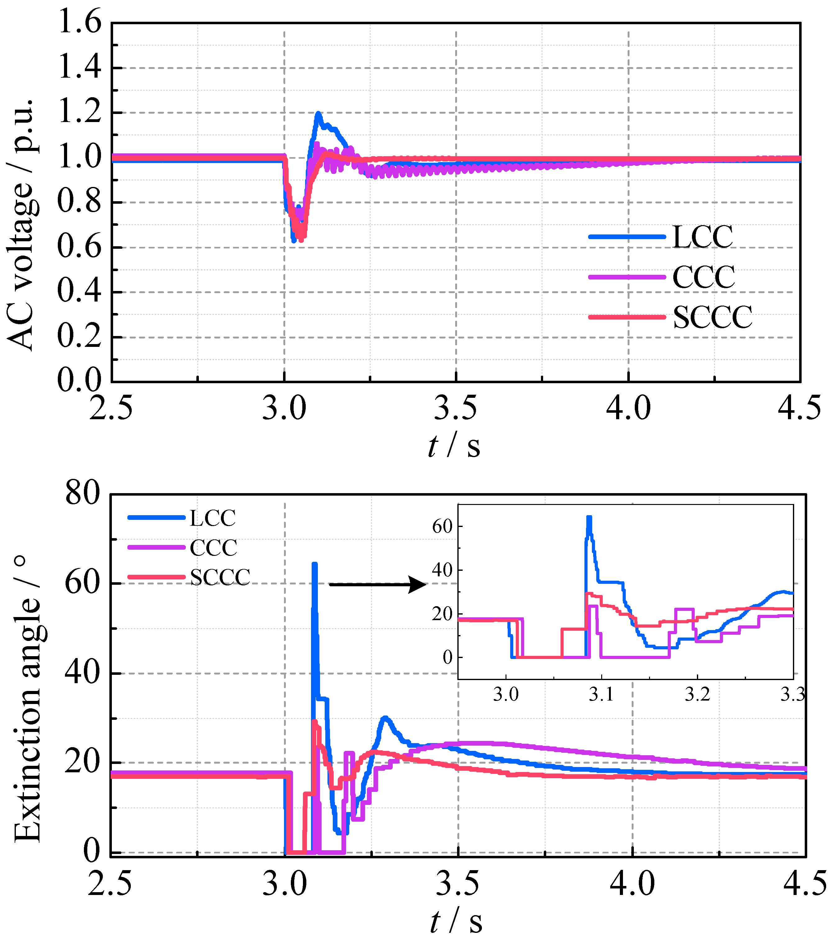
The SCCC incorporates an additional parallel path by the SC-STATCOM, which provides auxiliary commutation voltage and reactive power support during the AC faults. This enhances the commutation margin and accelerates post-fault voltage recovery. To evaluate the CF immunity and the fault recovery capability of the SCCC, typical AC system grounding faults at the inverter side are simulated. The transient characteristics are compared among the LCC, the CCC and SCCC.
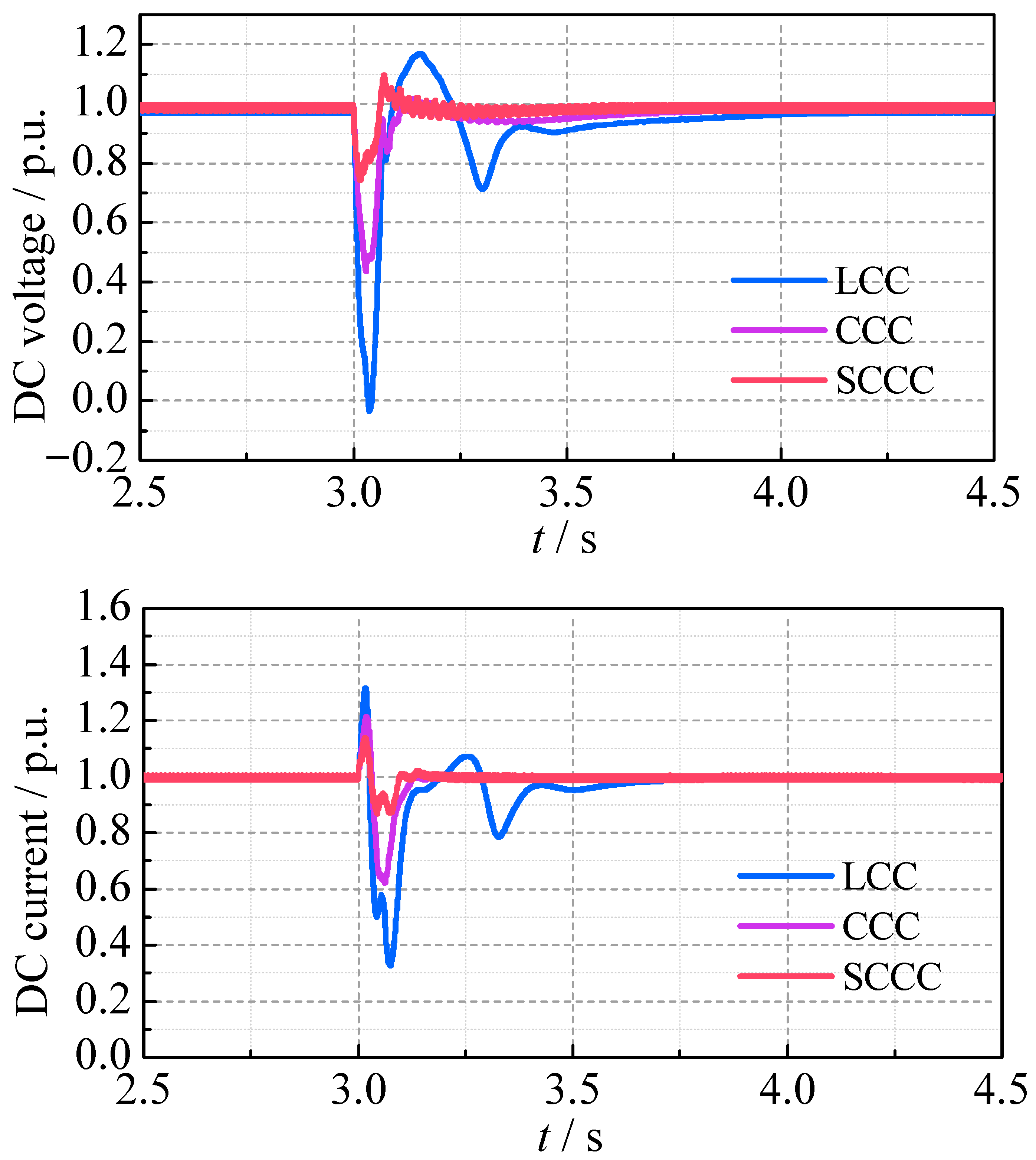
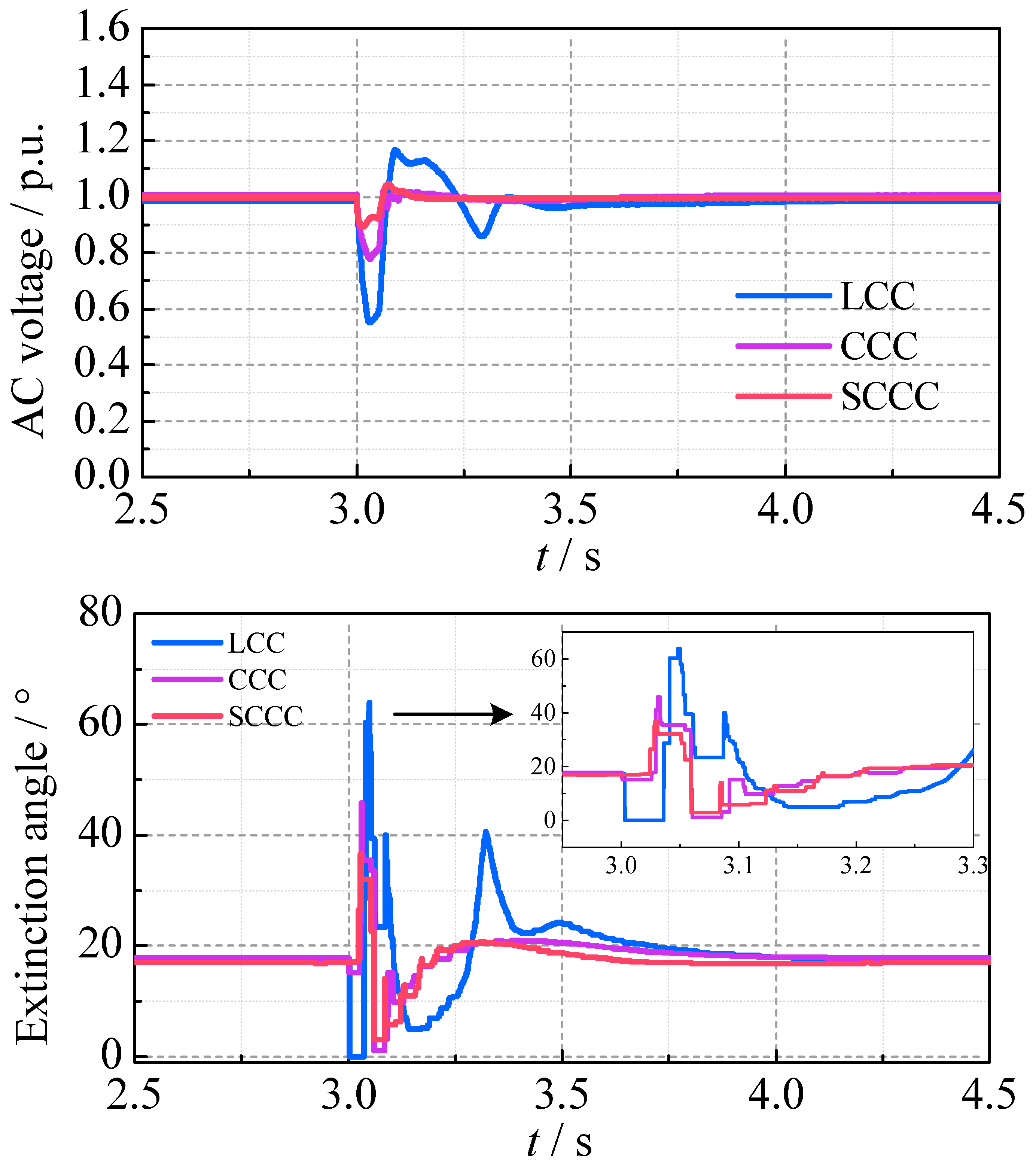
4.2.1. Non-Severe Three-Phase Grounding Fault
A three-phase grounding fault with a 100 Ω grounding resistance is applied to the inverter-side AC bus at 3.0 s, lasting 0.05 s. The transient waveforms of the three cases are compared in
Figure 11, and the SC-STATCOM reactive power output is shown in
Figure 12.
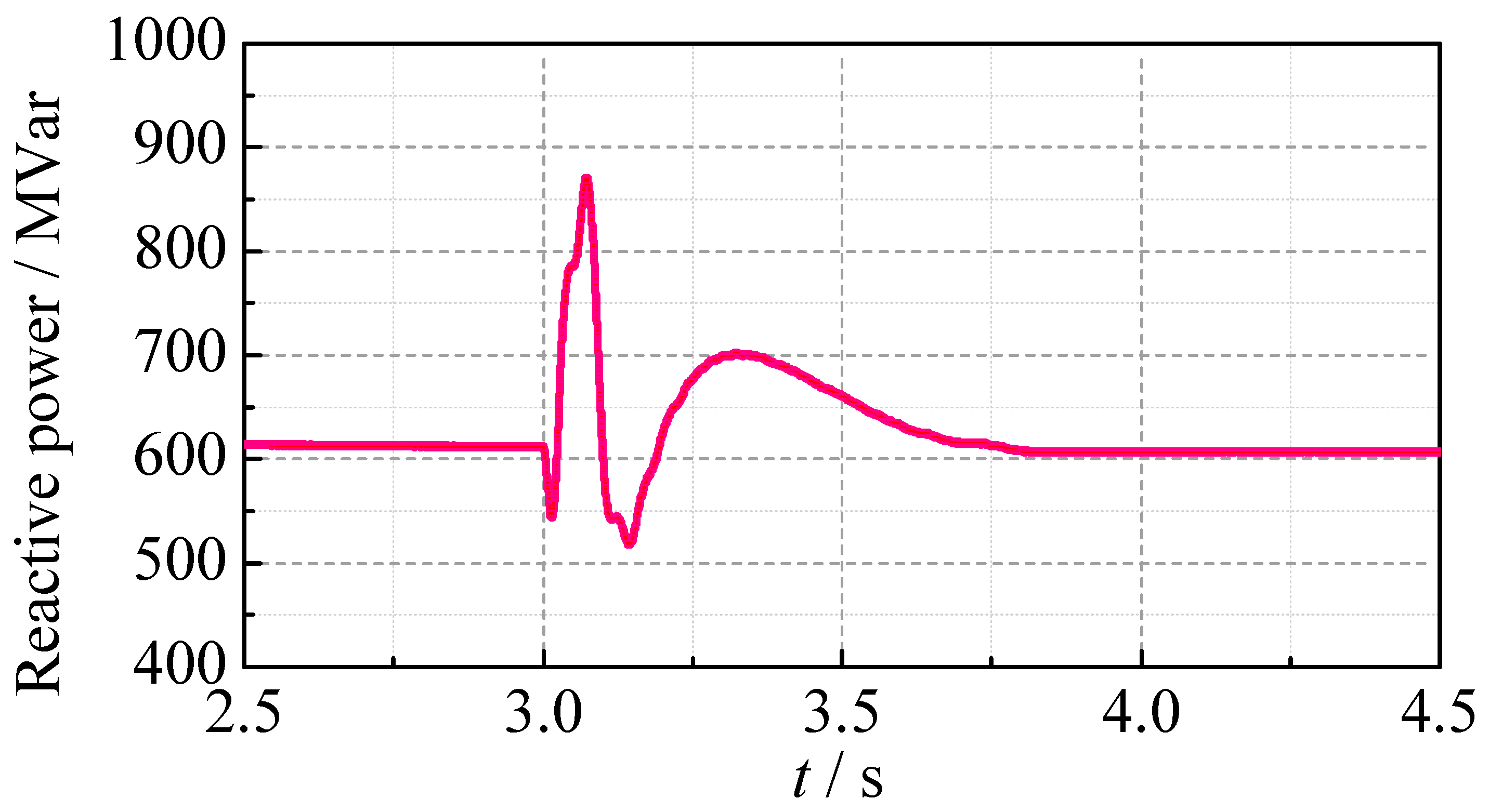
It can be seen that only the LCC experiences the CF, with its extinction angle rapidly dropping to zero, DC voltage reducing to zero, and DC current peaking at 1.32 p.u. The AC bus voltage at the inverter side drops to 0.55 p.u. In contrast, the CCC and SCCC can avoid the CF, with the maximum DC currents of 1.21 p.u. and 1.14 p.u., the minimum DC voltages of 0.43 p.u. and 0.71 p.u., and the minimum AC bus voltages of 0.77 p.u. and 0.89 p.u., respectively. During the AC fault, the SCCC shows the smallest DC overcurrent and provides enhanced reactive power support by the SC-STATCOM. The SCCC significantly improves the AC bus voltage stability compared to the LCC and CCC. After the AC fault is cleared, the LCC shows a large extinction angle impulse and minor oscillations in the DC voltage and the DC current. Meanwhile, the CCC and the SCCC achieve a smoother and faster recovery, with the SCCC demonstrating the fastest waveform recovery process. The SC-STATCOM provides 612 MVar of the reactive power during the steady-state operation process and 870 MVar during the transient process. The main transient parameters for the three converters are summarized in
Table 5.
4.2.2. Severe Single-Phase Grounding Fault
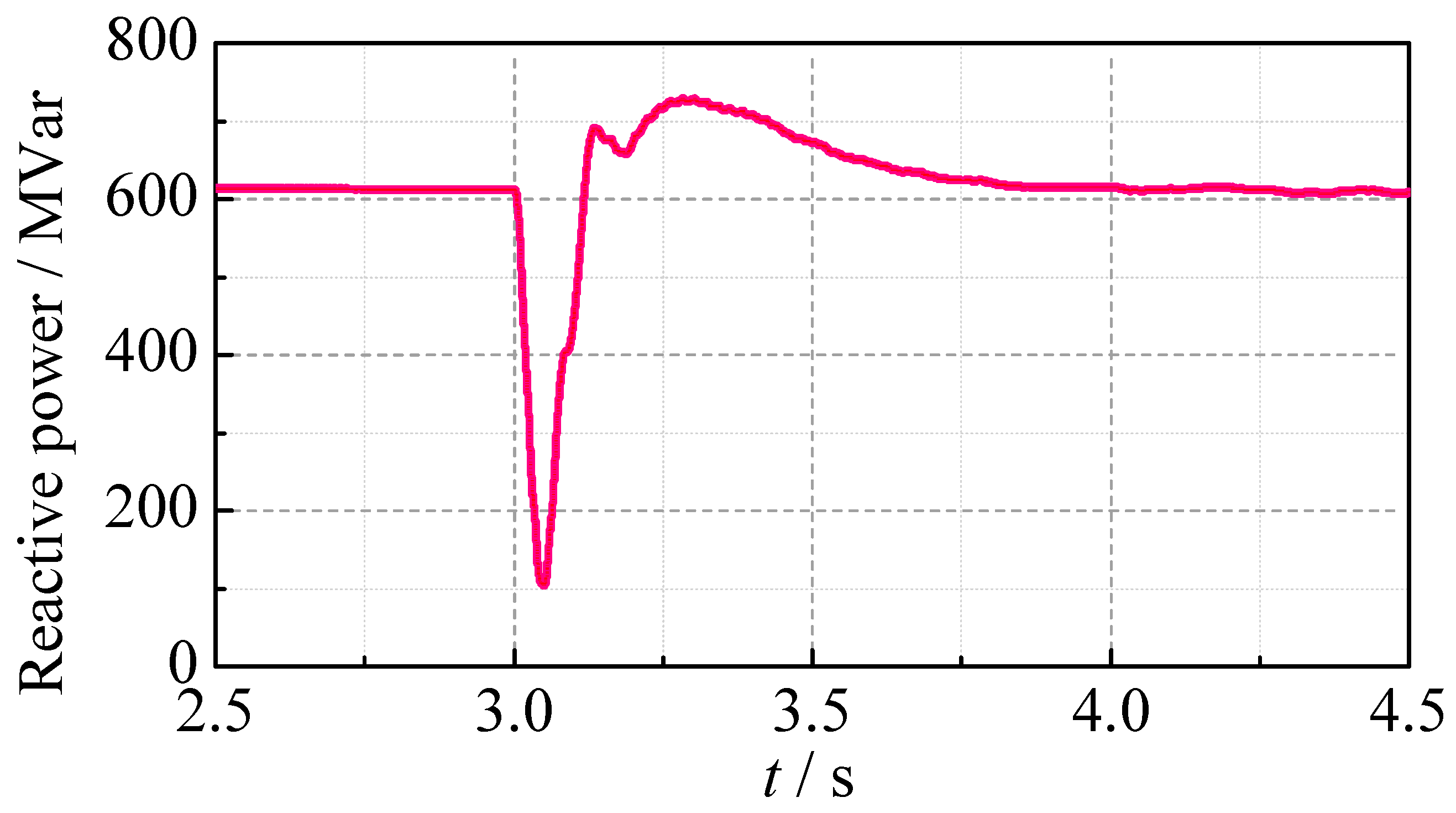
A c-phase grounding fault with a 0.01 Ω grounding resistance is applied to the inverter-side AC bus at 3.0 s, lasting 0.05 s. The transient waveforms of the three cases are compared in
Figure 13, and the SC-STATCOM reactive power output is shown in
Figure 14.
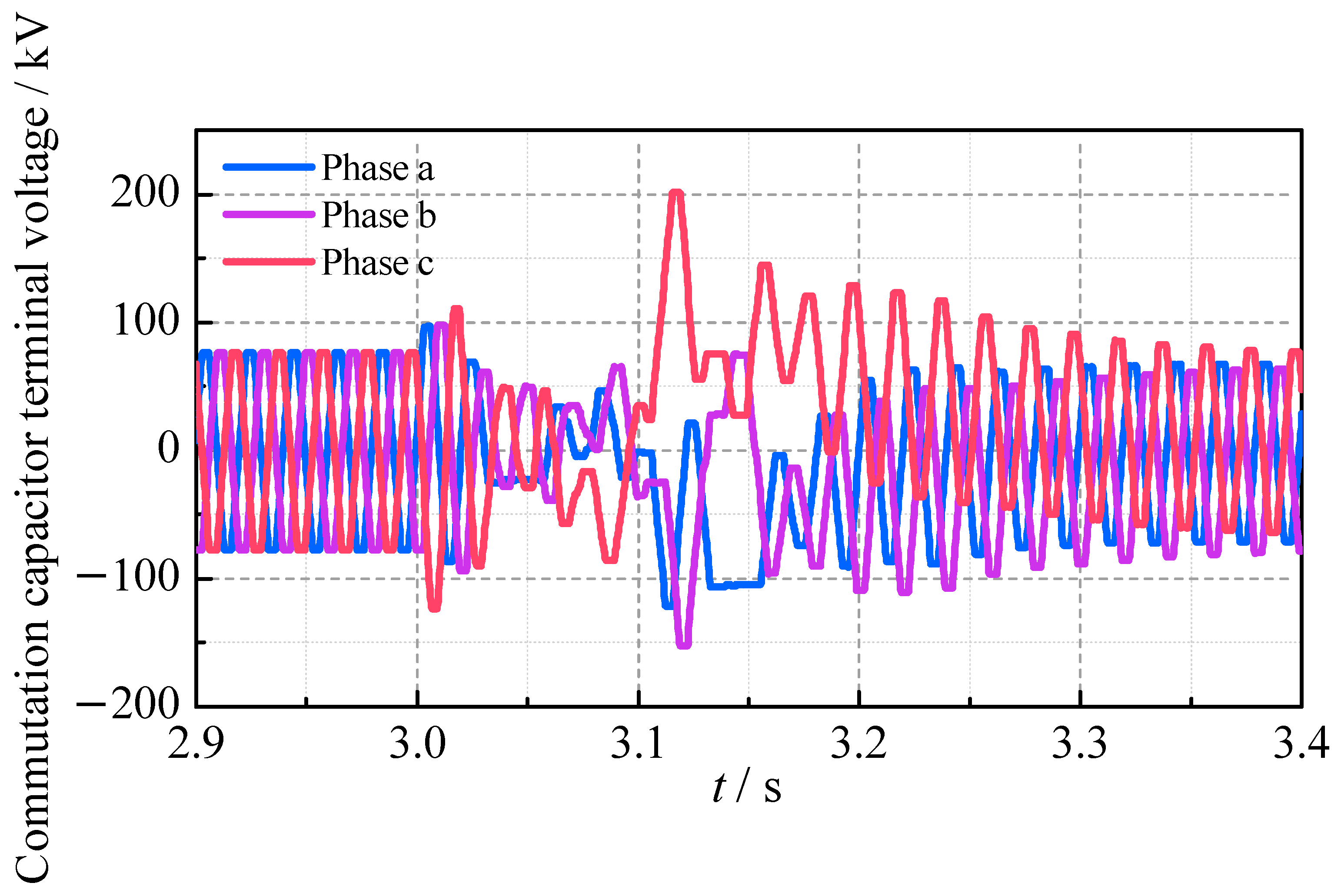
It can be seen that all three cases experience CF after the fault, with the extinction angles and DC voltages dropping to zero. The maximum DC currents reach 1.33 p.u. for the LCC, 1.27 p.u. for the CCC and 1.35 p.u. for the SCCC, while the minimum AC bus voltages at the inverter side drop to 0.61 p.u., 0.70 p.u. and 0.64 p.u., respectively. During the fault, both the CCC and the SCCC provide better AC voltage supporting capacity than the LCC. After the AC fault is cleared, the LCC and the SCCC recover smoothly, with the SCCC achieving the fastest voltage and current waveform recovery. However, the CCC shows a slow extinction angle recovery and continuous CF, resulting in a longer DC voltage recovery time of 1215 ms. The terminal voltage of the commutation capacitor during the AC fault is shown in
Figure 15.
It can be seen that the c-phase commutation capacitor charges continuously to an overvoltage state after the initial CF. This results in the unipolar terminal voltage of the commutation capacitor in the following several power–frequency cycles after 3.1 s, causing the excessive or insufficient actual commutation voltage. Then the normal turn-off/turn-on process of the c-phase thyristor valves is disrupted and the trigger sequence is disordered, leading to the continuous CF. Additionally, the characteristic of the commutation capacitors charging to overvoltage during the fault also requires the commutation capacitors to have greater overvoltage tolerance than their steady-state values.
In contrast, the SCCC mitigates these issues through the SC-STATCOM. On the one hand, the SC-STATCOM can regulate the charging rate of the commutation capacitors connected to the abnormal turn-off valves. On the other hand, the SC-STATCOM can adjust the commutation voltage by the reactive power compensation, reducing the impact of the abnormal capacitor charging on the commutation voltage.
The SCCC cannot prevent the initial CF after the severe single-phase grounding fault. However, it improves the fault recovery characteristics by providing the reactive power to support the AC voltage, thereby avoiding the continuous CF. The main transient parameters for the three converters are summarized in
Table 6.
4.3. Commutation Failure Immunity Index Analysis
The commutation failure immunity index (CFII) quantifies the ability of an inverter to resist CFs [
38], defined as follows:
where
Uac is the rated AC bus voltage at the inverter side. ω is the angular frequency.
Pd is the rated DC power.
Lmin is the minimum grounding inductance under which no CF occurs for any AC fault type.
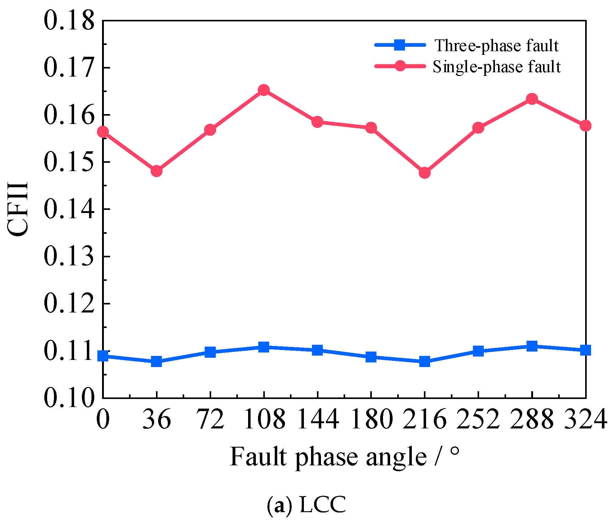
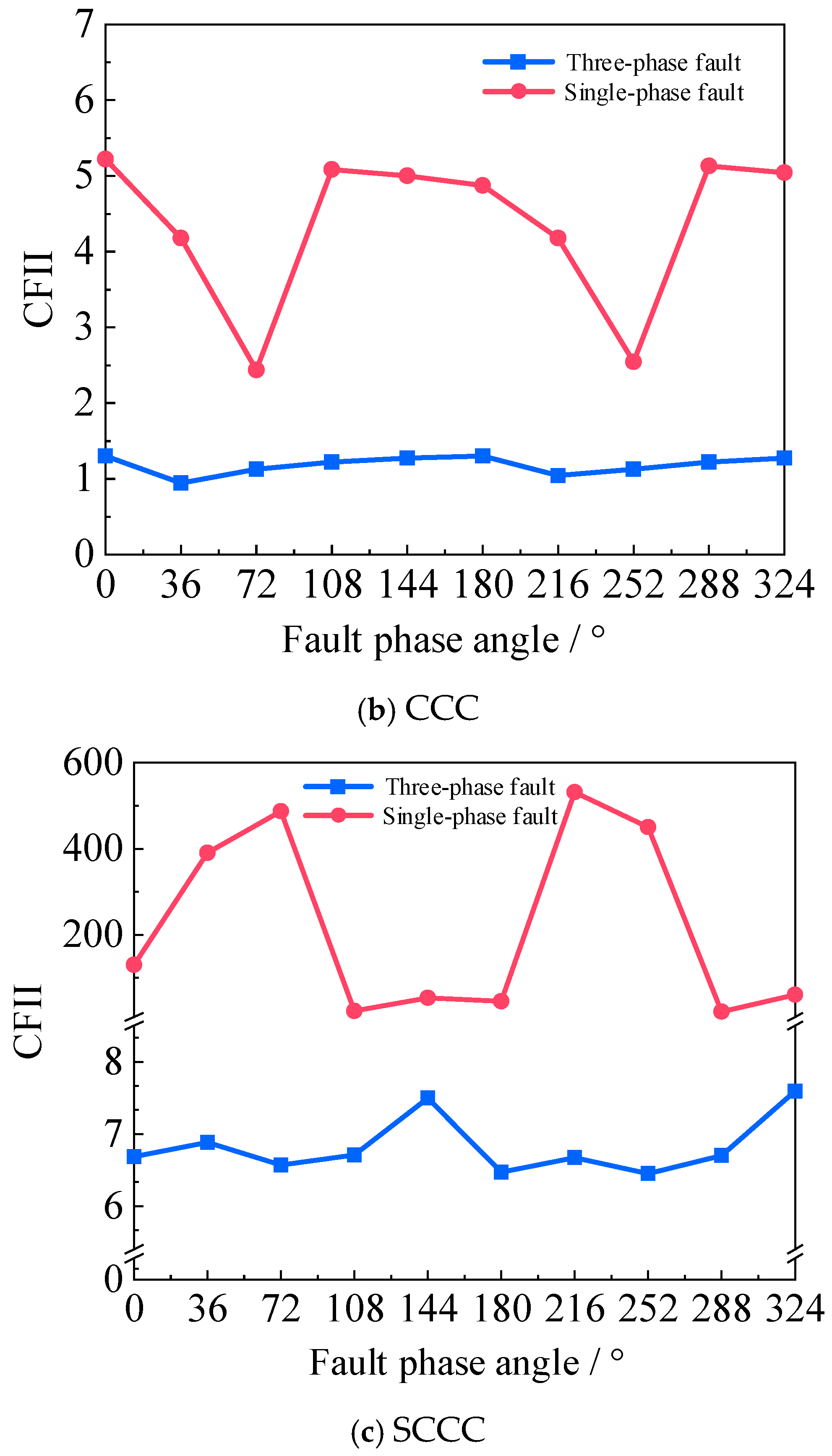
To evaluate the CF immunity of the SCCC, critical fault conditions are simulated via electromagnetic transient analysis. The AC system strength and the converter control are considered to calculate the CFII.
Different moments of the AC fault within a power–frequency cycle can cause different AC line voltage phase angles, then causing different transient fault responses of the commutation capacitor terminal voltages especially for the CCC and the SCCC. Therefore, when analyzing the CFII of the three converters, the occurrence time of the AC fault needs to be considered. Taking the zero-crossing point of the AC line voltage
uca from positive to negative half-wave as the reference (0°), a full cycle (0~360°) is divided into 10 intervals with a step of 36°. The electrical angle between the fault occurrence time and the reference (0°) is defined as the fault phase angle. For each fault phase angle, three-phase and single-phase faults with the fault duration of 0.05 s are simulated in PSCAD/EMTDC to determine
Lmin and then calculate the CFII. The CFII curves for the three converters under three-phase and single-phase faults are shown in
Figure 16.
The CFII curves demonstrate that the LCC exhibits the lowest CF immunity, followed by the CCC, while the SCCC achieves the highest CFII. It confirms that integrating commutation capacitors improves the CF resistance, and further adding the SC-STATCOM reduces Lmin, thus mitigating the CF probability. Additionally, single-phase faults result in higher CFII values than three-phase faults for the same converter, indicating that the converters show a better CF immunity under single-phase conditions.
Notably, the CCC and the SCCC exhibit a deeper CFII curve drop at specific single-phase fault angles. This is because the insertion of the commutation capacitor will increase the additional commutation voltage, and different fault phase angles can lead to different residual terminal voltages of the commutation capacitor at the moment of the fault occurrence, resulting in different initial voltages for the subsequent abnormal charge and discharge process of the commutation capacitor. Under the specific fault phase angle, it may be easier to cause the CF.
Simulations are conducted under the fault conditions corresponding to the lowest points of the CFII curves for the three converters. The minimum value of the AC bus voltage during the fault process can be obtained, defined as the critical AC voltage. The specific calculated values are shown in
Table 7.
When the AC bus voltage at the inverter side is lower than the critical AC voltage, there is a high probability of CF in the system. This indicates that the smaller critical AC voltage represents a stronger ability to resist the CF. As shown in
Table 7, the critical AC voltage of the SCCC is smaller than that of the CCC and the LCC. Therefore, the SCCC can avoid the CF under lower transient AC voltage conditions, demonstrating a better resistance against the CF.
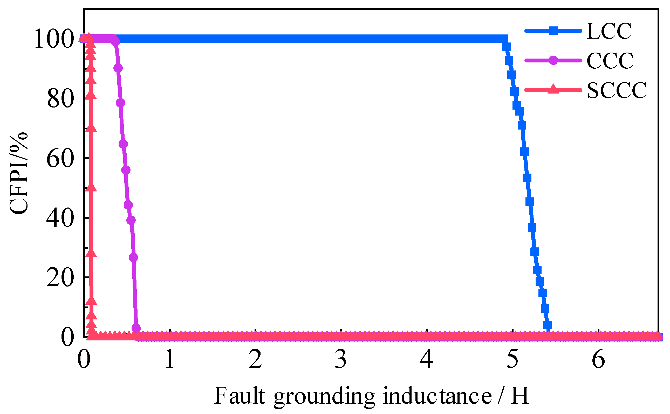
4.4. Commutation Failure Probability Index Analysis
Since the CFII can only represent the minimum grounding inductance value at which the system exactly does not experience the CFs, it cannot reflect the system characteristics under other grounding inductance values. To comprehensively compare the immunity of the CF for the three converters, the commutation failure probability index (CFPI) is used for evaluation and analysis. This index is defined as the ratio of the number of the CFs occurring within a power–frequency cycle to the total number of the simulations [
39]. The specific calculation process is as follows:
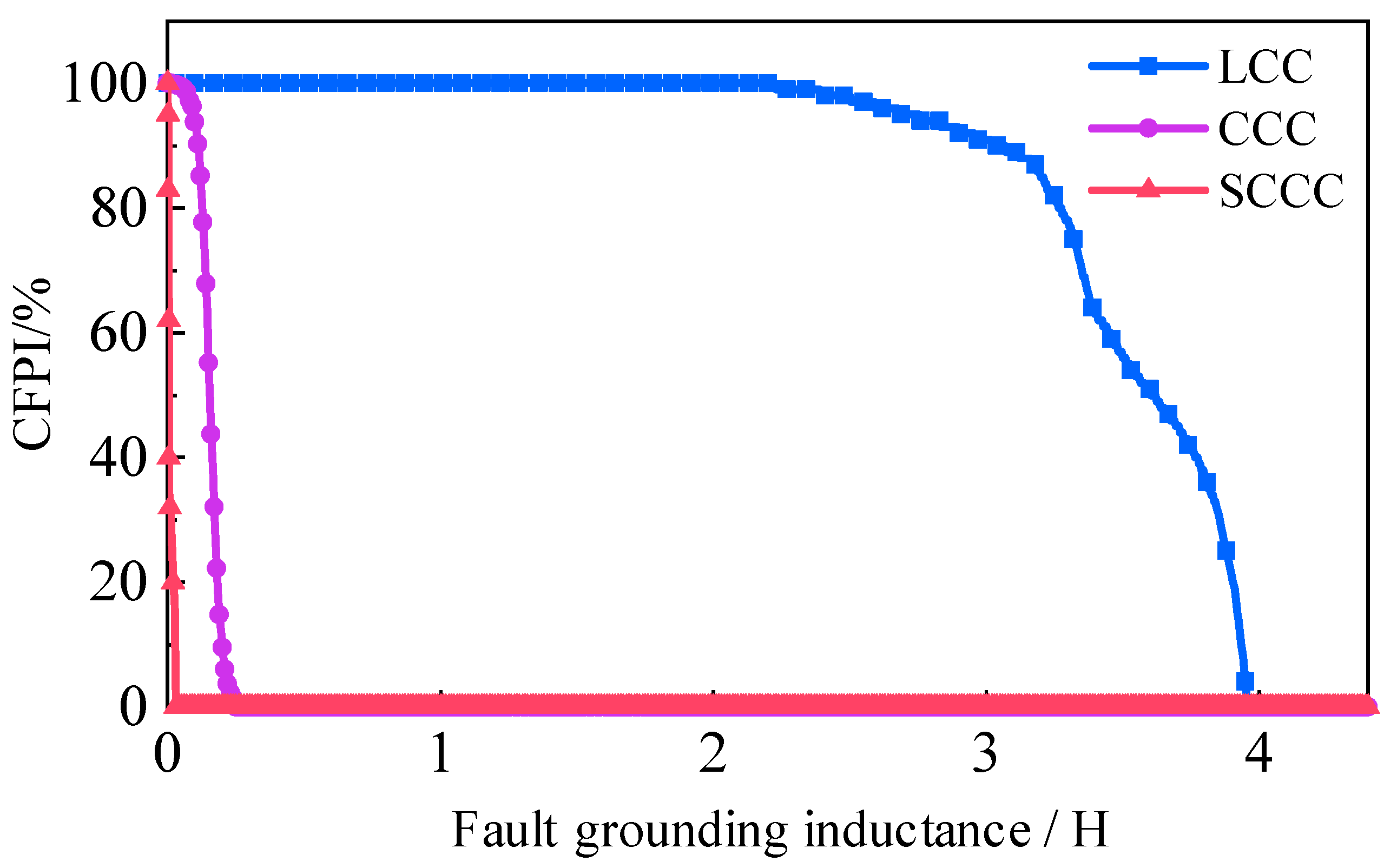
In one cycle of industrial frequency AC voltage, it is uniformly divided into 100 moments, forming 100 fault phase angles. A fixed three-phase or single-phase fault grounding inductance is set at the inverter side, with a fault duration of 0.05 s. All fault phase angles are considered, and the number of CFs is recorded and the proportion of this number in the 100 fault phase angles is calculated. This ratio is the CFPI value. By changing the fault grounding inductance, the CFPI value is recalculated. Finally, the CFPI curve is drawn.
Figure 17 and
Figure 18, respectively, show the CFPI curves for three converters under three-phase and single-phase grounding fault conditions.
It can be seen that when the fault grounding inductance is large, the CFPI value is 0%. When the fault grounding inductance is small, the CFPI value is 100%. There are some fault grounding inductances where not all cases of the fault phase angles experience the CFs. The minimum horizontal coordinate value where the CFPI curve intersects the horizontal axis corresponds precisely to the minimum grounding inductance value Lmin in the CFII. Additionally, the further the CFPI curve is to the right, the greater the probability of the CF under the same severity of the fault. From the comparison of the curves, the SCCC has a lower probability of CFs under the same fault conditions compared to the CCC and the LCC. Therefore, it can be concluded that the SCCC technology is capable of resisting CFs under the more severe grounding short circuit faults.
From the above analysis, the technical features for the three converters are compared and summarized in
Table 8.
5. Conclusions
The uncontrollable charging of the commutation capacitors may lead to continuous CFs for the CCC technology. This paper presents a new topology named SCCC to effectively reduce the risk of continuous CFs in the CCC. The main conclusions of this paper are as follows:
(1) The CCC reduces the reactive power demand to 18% of the rated power vs. 50% for the LCC. After the SC-STATCOM capacity is set as approximately 23% of the rated power, the SCCC can omit the installation of the reactive power compensation devices and the AC filters.
(2) When the direct current increases, the active power decrease of the SCCC is the smallest among the three converters, and its MPC curve is positioned the furthest to the upper right. It indicates that the SCCC can enhance the maximum available power, increase the strength of the AC system and improve the apparent SCR of the AC system at the inverter side. Furthermore, increasing the SCR or the capacity of the SC-STATCOM can increase the MAP value of the SCCC and enhance the static stability limit of the system.
(3) The SCCC has the ability to mitigate the possibility of the initial CF during the non-severe three-phase grounding fault and avoid the continuous CF during the severe single-phase grounding fault to some extent. Thus, the SCCC has a great immunity of CFs during AC faults. Meanwhile, it has better fault recovery characteristics than the LCC and the CCC.
(4) The SCCC cannot thoroughly avoid the occurrence of the initial CF during the severe single-phase grounding fault. Future work will focus on the control strategy of the SC-STATCOM to improve the transient characteristics during severe asymmetric faults. Meanwhile, the economic assessment and the engineering application of the SCCC technology will be studied in the following research.


