Article

Novel Design of Three-Channel Bilateral Teleoperation with Communication Delay Using Wave Variable Compensators

1
School of Automation Engineering, University of Electronic Science and Technology of China, Chengdu 611731, China
2
Department of Robotics, LIRMM, University of Montpellier—CNRS, 34095 Montpellier, France
3
euroDAO SAS, 34095 Montpellier, France
4
Department of Industrial and Systems Engineering, The Hong Kong Polytechnic University, Hong Kong, China
5
Department of Computer Science and Engineering, Hanyang University, Ansan 15577, Republic of Korea
6
Department of Electrical and Computer Engineering, Texas A&M University, College Station, TX 77843, USA
*
Author to whom correspondence should be addressed.
Electronics 2025, 14(13), 2595; https://doi.org/10.3390/electronics14132595 (registering DOI)
Submission received: 27 May 2025 / Revised: 20 June 2025 / Accepted: 24 June 2025 / Published: 27 June 2025
(This article belongs to the Special Issue Intelligent Perception and Control for Robotics)

Abstract

Bilateral teleoperation systems have been widely used in many fields of robotics, such as industrial manipulation, medical treatment, space exploration, and deep-sea operation. Delays in communication, known as an inevitable issues in practical implementation, especially for long-distance operations and challenging communication situations, can destroy system passivity and potentially lead to system failure. In this work, we address the time-delayed three-channel teleoperation design problem to guarantee system passivity and achieve high transparency simultaneously. To realize this, the three-channel teleoperation structure is first reformulated to form a two-channel-like architecture. Then, the wave variable technique is used to handle the communication delay and guarantee system passivity. Two novel wave variable compensators are proposed to achieve delay-minimized system transparency, and energy reservoirs are employed to monitor and regulate the energy introduced via these compensators to preserve overall system passivity. Numerical studies confirm that the proposed method significantly improves both kinematic and force tracking performance, achieving near-perfect correspondence with only a single-trip delay. Quantitative analyses using Root Mean Square Error (RMSE), Mean Absolute Error (MAE), and Dynamic Time Warping (DTW) metrics show substantial error reductions compared to conventional wave variable and direct transmission-based three-channel teleoperation approaches. Moreover, statistical validation via the Mann–Whitney U test further confirms the significance of these improvements in system performance. The proposed design guarantees passivity with any passive human operator and environment without requiring restrictive assumptions, offering a robust and generalizable solution for teleoperation tasks with communication time delay.

1. Introduction

The first modern bilateral teleoperation system was developed in 1949 by Goertz [1] to handle radioactive materials in nuclear facilities. Over the decades, teleoperation technology has undergone significant advancements, evolving from basic unilateral control mechanisms to sophisticated systems integrating haptic feedback for enhanced user interaction. A typical bilateral teleoperation system consists of a master controller and a remote robotic manipulator, enabling operators to perceive and respond to the physical conditions of a remote environment in real time. This capability has made teleoperation indispensable in a variety of critical applications, including bomb disposal, underwater exploration, minimally invasive surgery, and the operation of unmanned aerial and ground vehicles [2,3,4,5].
For bilateral teleoperation system, there are two important performance evaluation indices: stability and transparency [6]. As in other control systems, stability is always the primary objective to achieve and guarantee. However, in the communication channel of bilateral teleoperation system, it is inevitable to contain certain time delay, which will destroy the passivity of the teleoperation system and thus cause potential threats to the operation stability and safety. Therefore, how to deal with the time delay and maintain the system stability has been a key issue in the research of bilateral teleoperation system. For constant time delays, scattering theory has been instrumental in ensuring system passivity and stability. Anderson and Spong [7] introduced a control law utilizing passivity and scattering theory to stabilize bilateral teleoperators under time delays. Niemeyer and Slotine [8] further developed this approach by introducing wave variables to handle arbitrary time delays in teleoperation. Numerous research works have been carried out to guarantee teleoperation system stability with constant communication time delay based on these techniques ever since. Alise et al. [9] explored the enhancement of the wave variable method by generalizing it to include a broader family of impedance matrices for multiple degrees of freedom (DOF) systems. Polushin [10] proposed a generalized scattering framework that was designed in order to enhance flexibility in control design while maintaining stability in teleoperation systems with constant communication delays. Najafabadi et al. [11] proposed a synchronization control approach combined with a novel disturbance observer tailored for nonlinear passive bilateral teleoperation systems with constant time delays by consolidating unknown dynamic factors into a single disturbance signal to enhance system stability and performance. In [12], a comprehensive overview of discrete-time control methods for bilateral teleoperation systems with communication time delays was presented, evaluating existing techniques like passivity and wave variable methods and emphasizing their stability and transparency in teleoperated environments. Recent research efforts have been made to address the problem of variable communication time delays due to factors such as fluctuating network traffic, dynamic routing decisions, and varying levels of congestion in communication channels. Numerous research results have been obtained using various control techniques like adaptive wave variable control [13], time-varying passivity control [14], Lyapunov–Krasovskii functionals [15], predictive adaptive control [16], robust control [17], etc. Notably, new neural network and learning-based methods have been used to address the variable time delay issue. For example, in [18] a long short-term memory (LSTM)-based Bilateral Active Estimation Model (BAEM) is proposed for estimating the time delay in both directions of the teleoperation system. In [19], an adaptive fixed-time control strategy has been proposed for a class of nonlinear bilateral teleoperation systems with variable time delays, and radial basis function neural networks (RBFNNs) were utilized to estimate uncertainties in the teleoperation systems. Dao et al. [20,21] proposed novel Robust Integral of the Sign of the Error (RISE)-based reinforcement learning (RL) and actor–critic reinforcement learning algorithms for the optimal effectiveness of bilateral teleoperators with variable communication delays and uncertain dynamics.
On the other hand, transparency is used as another important performance evaluation criterion to measure the perception capability of the master operator to the slave environment in a bilateral teleoperation system. It is well known that “passivity and transparency are conflicting objectives in teleoperator system design” and perfect passivity and transparency can only be realized with four-channel architecture in idea case without presence of communication time delay [6]. In practice, trade-off between passivity and transparency is always necessary for a bilateral teleoperation design. While keeping system stability, researchers have worked towards improving transparency in bilateral teleoperation. Coelho et al. [22] investigated how wave variable transformations impact human haptic perception, and they revealed that, while the generalized wave variable approach generally outperforms the original in rendering mass and stiffness, both methods’ effectiveness diminishes as time delays increase, making accurate perception challenging during dynamic interactions. In [23], a novel control framework was proposed to directly compensate for time delays in bilateral teleoperation systems while maintaining stability and transparency through combining direct delay compensation with predictive control techniques. Chen et al. [24] introduced an enhanced four-channel control architecture that integrates wave variable transformations and aimed to improve transparency by effectively compensating for the adverse effects of communication delays, thereby enhancing the operator’s perception and control of the remote environment. Balachandran [25] introduced a nonlinear gain for local force feedback control and discussed ensuring passivity through model-dependent and model-independent methods, along with proposing a passive reference coupling (PCR) method in order to improve the haptic feedback performance of teleoperation systems, particularly under conditions of large and time-varying delays.
According to the number of communication channels or type of signals exchanged between the master and slave of the bilateral teleoperation system, the teleoperation structures can be divided into four-channel control structure (4CH), three-channel control structure (3CH), and two-channel control structure (2CH). 4CH structure was proposed and analyzed in detail by Lawlrence in 1993 [6] and this control structure includes transmission of all four signals between master and slave, namely bidirectional force and motion (velocity or position). Later on, Hashtrudi-Zaad et al. improved the 4CH structure by adding local force feedback controller and local position controller so that the system could achieve perfect transparency under the ideal condition without a time delay [26]. Moreover, 4CH architectures, though capable of achieving ideal transparency under ideal conditions, are more complex and difficult to implement in practice, especially in the presence of communication delay. In reality, the 2CH structure has been employed in many practical applications due to its minimum number of communication channels needed, which can greatly reduce the control design effort and hardware cost compared to the 4CH control structure. Many bilateral teleoperation systems in the recent literature are based on the 2CH architecture, including most of the aforementioned works, particularly those involving neural network and learning-based approaches. The simple configuration of the 2CH system facilitates the control design to guarantee system stability, together with position/velocity tracking with and without communication delay, but on the other side, transparency, as a conflicting objective, is often neglected or sacrificed due to the limited feedback signals and control design freedoms. Recent works continue to advance passivity-based control for delay-affected teleoperation, such as robust nonlinear controllers under varying delays and loads [27], hybrid delay-mitigation strategies combining wave variable and predictive elements [28], and hardware-validated passivity control frameworks [29]. However, these studies remain confined to 2CH architectures. To our knowledge, no learning-based or data-driven methods have been developed for 3CH configurations. The 3CH structure can be seen as a balanced compromise between the 4CH and 2CH structures. It offers an additional degree of freedom for control design compared to the 2CH structure while maintaining a lower implementation cost than the 4CH structure. In [30], Albakri et al. evaluated the stability and transparency of all four possible three-channel control structures without a time delay in the context of medical applications, which provides a design framework for telesurgery and recommends the P-PF (Position, Position-Force) configuration as the most suitable 3CH solution. While 3CH architectures offer a practical compromise between 2CH simplicity and 4CH performance, they remain underexplored and lack robust methods to ensure passivity and high transparency simultaneously without restrictive assumptions. To our knowledge, no learning-based methods have been developed for 3CH configurations in literature either. In [26], the stability and transparency of two 3CH teleoperation configurations under constant communication delay were studied through a characteristic equation analysis. The authors derived conditions for achieving stable and optimally transparent control, but these results were limited to specific classes of human operators and environments that satisfy complex and non-trivial constraints. Building on this, ref. [31] introduced wave variable-based 3CH teleoperation designs following the conventional framework in [8] to preserve system passivity under delay. However, this approach incurred a significant reduction in transparency due to signal distortion, making it more suitable for scenarios involving asymmetric dynamics, such as a heavy master or heavy slave device.
In this work, we propose a 3CH teleoperation system design that can guarantee absolute stability and, meanwhile, maximize system transparency in the presence of communication delay. We focus on constant communication delays, as this study is tailored to robotic surgery in a practical operating room (OR) environment. Our previous research on the wireless teleoperation of miniaturized surgical robotic instruments has shown that wireless Zigbee communication within the OR remains stable, exhibiting a variance of only ±0.2 ms [32]. Given this consistency, assuming a constant time delay is both reasonable and reflective of real-world surgical applications. In order to achieve this objective, we first reformulate the 3CH to its equivalent 2CH-like form to facilitate the control design using wave variable technique, ensuring system passivity against time delay and leveraging its wide applicability to all passive operators and environments. To remedy the bias terms introduced via conventional wave variable design that significantly degrades system transparency, two wave variable compensation terms are proposed to improve the kinematic and impedance tracking performances. Energy reservoirs are constructed to monitor and handle potential extra energy caused by the two wave variable compensators and guarantee overall system passivity. This proposed method provides a new wave variable perspective for 3CH teleoperation system design with the presence of a communication delay and enables further studies of 3CH teleoperation using wave variable-relevant techniques in the literature.
In summary, the main contributions of this paper are as follows:
  • A novel wave variable compensator-based design is proposed for three-channel (3CH) bilateral teleoperation systems that ensures both delay-compensated stability and high transparency.
  • A two-step controller design framework is established, which first reformulates the 3CH system into a passive two-port network and then designs the wave variable compensators, together with energy reservoirs, to ensure passivity under communication delay.
  • The effectiveness of the proposed method is validated through structured numerical comparisons against the conventional wave variable approach [31] using quantitative metrics including Root Mean Square Error (RMSE), Mean Absolute Error (MAE), Dynamic Time Warping (DTW), and the Mann–Whitney U test.
  • The proposed framework is theoretically extendable to other three-channel teleoperation configurations, offering a scalable and modular foundation for future developments in transparent and stable teleoperation under communication delay.
The rest of the paper is organized as follows: Section 2 briefly presents the fundamentals of three-channel bilateral teleoperation structure and traditional wave variable transformation. In Section 3, the wave variable compensator-based 3CH teleoperation system is proposed with detailed analysis of its transparency and the energy reservoirs designed to guarantee system stability. The numerical studies carried out to verify the effectiveness and advantages of the proposed method over conventional methods through comparisons are presented in Section 4, and finally, the conclusions are drawn in Section 5.
To improve the paper’s readability, a list of abbreviations is provided below in Table 1.

2. Fundamentals of Bilateral Teleoperation System with Time Delay

2.1. 4CH Teleoperation System with Time Delay

The structure of a four-channel (4CH) bilateral teleoperation system with a time delay [26] is shown in Figure 1, where F h * and F e * denote the operator and environment exogenous force inputs, F h and F e denote the operator force on the master device and the feedback force from interaction with the remote environment, v m and v s are velocities of master device and slave robots, and Z h , Z e , Z m , and Z s represent the impedance of the operator arm, environment, master device and slave robot. T denotes the time delay in communication channel. C i ( i = 1 , , 6 ) and C m , C s represent the controllers, where C 5 and C 6 are known as local force feedback controllers, and C m and C s are known as local position controllers.

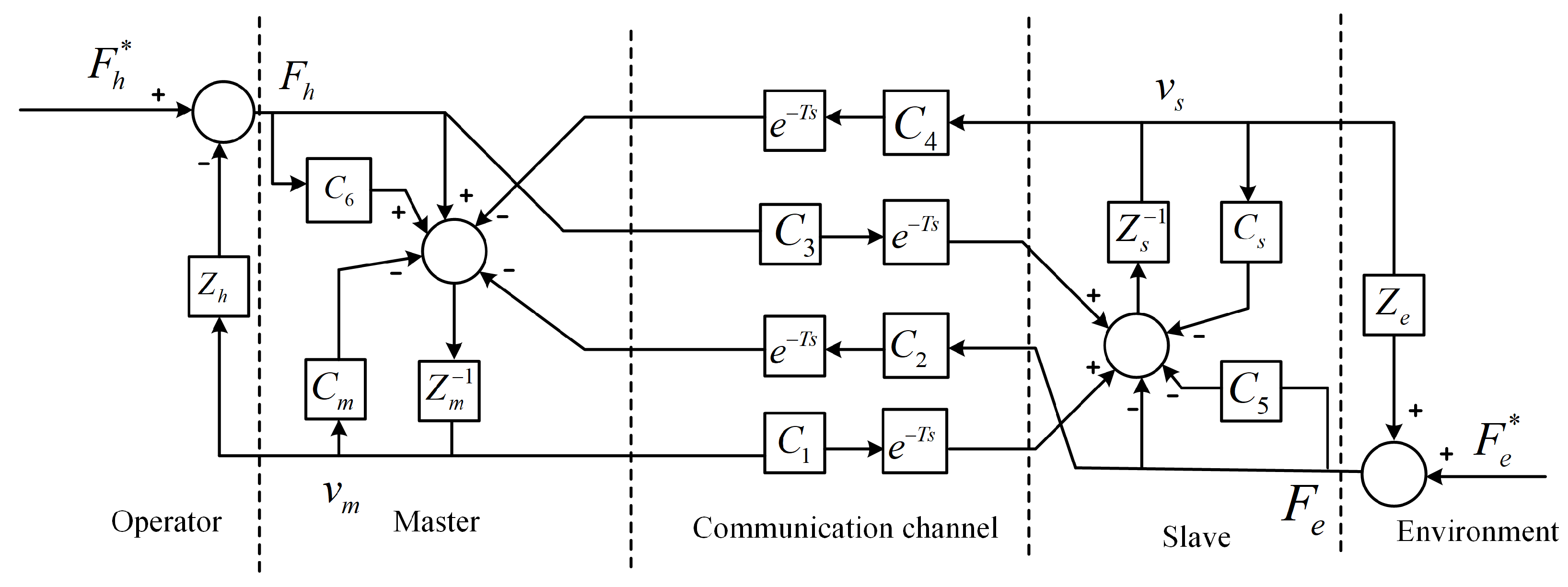
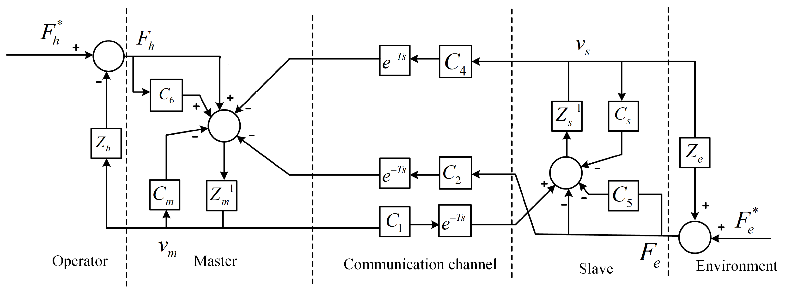
2.2. 3CH Teleoperation System with Time Delay

The three-channel (3CH) teleoperation structure is a structure that eliminates one channel on the basis of the 4CH structure to simplify the design and implementation of bilateral teleoperation system. By eliminating different channels, there are four possible configurations of three-channel teleoperation systems: the Position–Position Force control structure (P-PF), the Force–Position Force control structure (F-PF), the Position Force–Position control structure (PF-P), and the Position Force–Force control structure (PF-F) [30].
The study on bilateral teleoperation system in this paper is mainly dedicated to medical applications, such as robot-assisted remote surgery and remote ultrasonic diagnosis. In such application scenarios, the stiffness and damping parameters of environment are smaller than those of the operator in general. In this work, we adopt the P-PF structure that transfers motion (P) command signal from master to slave and feedbacks both motion (P) and force (F) signals from slave to master, as shown in Figure 2. This choice has been justified in our previous work in [30]. The P-PF structure is also referred to as the Environment-Force-Compensated (EFC) three-channel control architecture in [26] and is suitable for operations in which the operator is heavier, stiffer, and more damping than the environment.

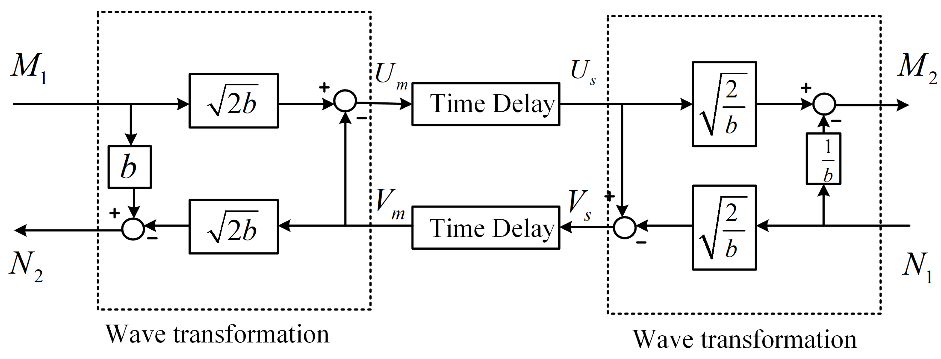
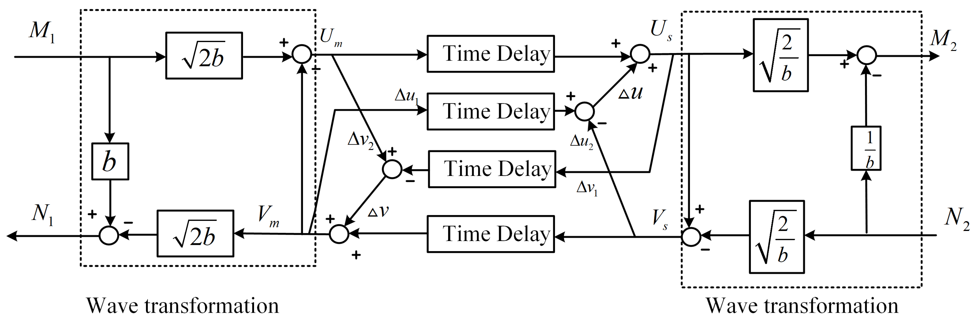
2.3. Wave Variable Transformation Method

Communication delays are well known to break the passivity of bilateral teleoperation systems, potentially leading to instability and unsafe interactions. To address this issue, the wave variable method was introduced as a passivity-preserving approach that reformulates power variables (e.g., velocity and force) into so-called wave variables before transmission [8]. By transforming the communication channel into a lossless two-port network, the method guarantees that the energy exchanged through the channel remains non-negative, even in the presence of a constant time delay. This ensures that the delayed communication link does not generate energy and thus preserves overall system stability. The formulation of the wave variables is shown in Figure 3.
One of the key advantages of the wave variable approach is its generality that allows stability to be maintained for arbitrary passive operators and environments, without requiring specific model assumptions. The method has become a foundational tool in teleoperation control design, and it serves as the basis for the proposed system developed in this work.
Following the wave variable formulation, as shown in Figure 3, the relationship between the power variables and the wave variables can be expressed as in the following:
U m ( t ) = 1 2 b ( N 2 ( t ) + b M 1 ( t ) )
V s ( t ) = 1 2 b ( N 1 ( t ) + b M 2 ( t ) )
U s ( t ) = 1 2 b ( N 1 ( t ) + b M 2 ( t ) )
V m ( t ) = 1 2 b ( N 2 ( t ) + b M 1 ( t ) )
where b is wave impedance, and U i and V i ( i = m , s ) represent the wave variables. It should be noted that M i and N i ( i = 1 , 2 ) are used to denote the generalized power variables on the master and slave side to facilitate the development for 3CH structure in next section. For a 2CH bilateral teleoperation system, M i denotes the master and slave velocity v m , v s , and N i denotes the environment interaction force F e and feedback force to the master F m , for i = 1 and 2, respectively.
Considering the communication delay, the relationship of the wave variables on both sides of the communication channels can be described as follows:
U s ( t ) = U m ( t T )
V m ( t ) = V s ( t T )
And from Equations (1)–(4), M 1 , M 2 , N 1 , and N 2 in Figure 3 can be expressed equivalently in the form of wave variables as follows:
M 1 ( t ) = 1 2 b ( U m ( t ) + V m ( t ) )
N 1 ( t ) = b 2 b ( U s ( t ) V s ( t ) )
M 2 ( t ) = 1 2 b ( U s ( t ) + V s ( t ) )
N 2 ( t ) = b 2 b ( U m ( t ) V m ( t ) )
Following such a formulation, the energy flow of the 2-port communication network can be derived as follows [8]:
E ( t ) = 0 t ( N 2 ( τ ) M 1 ( τ ) N 1 ( τ ) M 2 ( τ ) ) d τ = 1 2 t T t ( U m T ( τ ) U m ( τ ) + V s T ( τ ) V s ( τ ) ) d τ 0
which shows that the wave variable method can passivate the system against the communication delay. But on the other side, it comes at the cost of sacrificing the transparency in terms of force and motion tracking performances, as seen in the following equations:
M 2 ( t ) = M 1 ( t T ) + 1 b ( N 2 ( t T ) N 1 ( t ) ) bias
N 2 ( t ) = N 1 ( t T ) + b ( M 1 ( t ) M 2 ( t T ) ) bias
where the second terms on the right side of both equations are the bias terms that distort the transmitted signals and cannot be removed following the conventional wave variable method.
If these bias terms can be eliminated, then the power variables transmitted to the other side of the communication network will show phase lag of only one single time delay, T, which represents the delay-minimized tracking performance achievable without the delicate employment of predictors.

3. Wave Variable Compensator-Based 3CH Teleoperation System

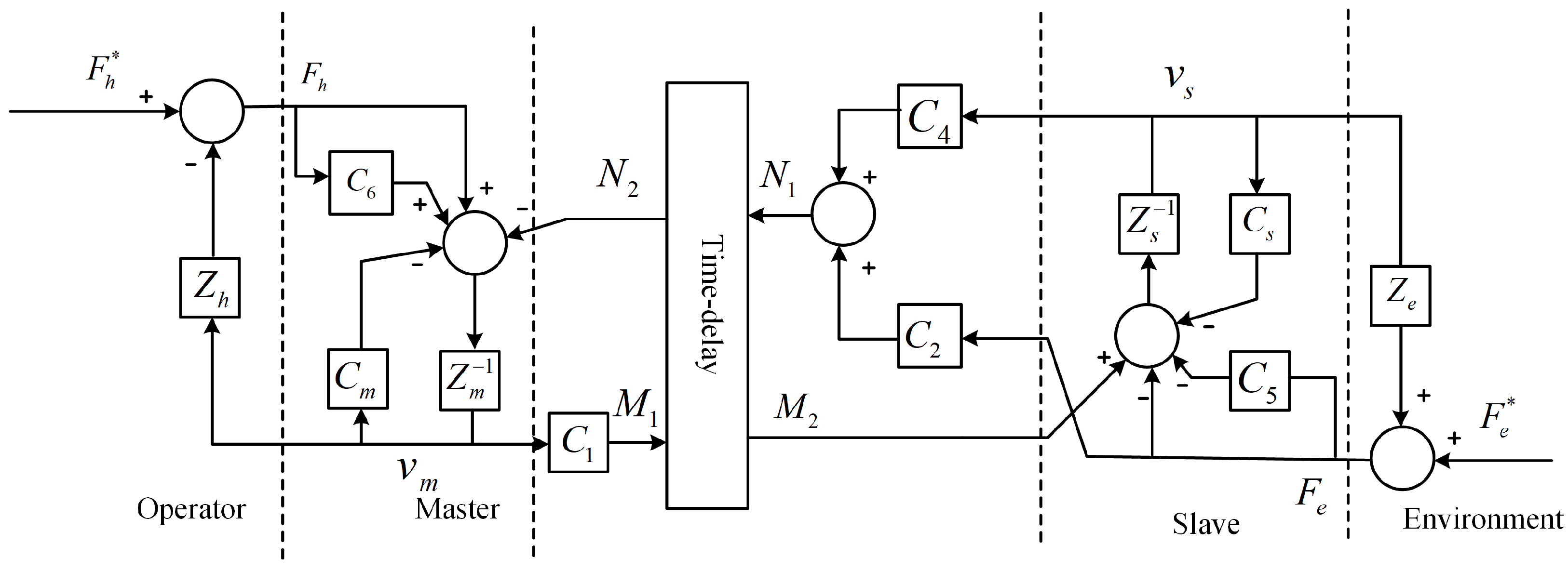
3.1. Reformulation of the P-PF 3CH Teleoperation Structure

Inspired by the result in [31], in this work, the three communication channels of the P-PF structure are firstly reformulated to form a 2-port communication port, as illustrated in Figure 4, to facilitate the implementation of the wave variable technique to handle the time delay in communication. The reformulated structure possesses a 2CH-like architecture. It should be noted that, in this case, the generalized power variables M 1 and N 1 are composed of
M 1 = C 1 v m
N 1 = C 4 v s + C 2 F e
where M 1 represents the master velocity command going through controller C 1 ; N 1 is the sum of the slave velocity and force signals going through controller C 4 and C 2 . And M 2 = M 1 e T s and N 2 = N 1 e T s are, respectively, their delayed generalized power variables.
The reformulated structure suffers from the same problem as conventional 2CH structure: if the power variables are transmitted directly through the communication channel the system passivity will be destroyed due to the time delay. Therefore, the wave variable technique is employed to passivate the overall teleoperation system.

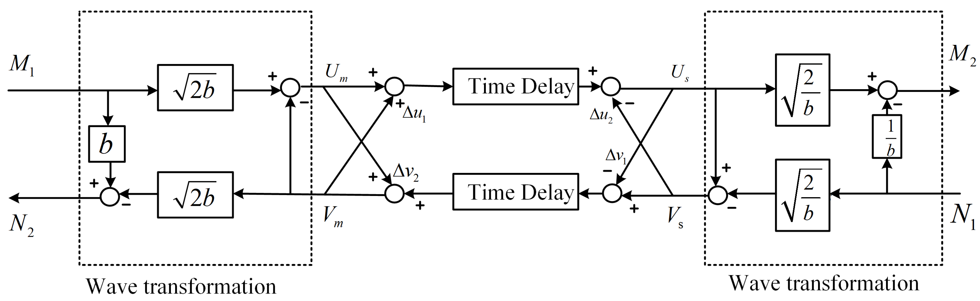
3.2. Wave Variable Compensator Approach to 3CH Teleoperation

3.2.1. Wave Variable Compensator Design

A straightforward implementation of the wave variable method leads to the bias problem, as shown in Equations (12) and (13) of last section. In order to improve the tracking performance, two wave variable compensation terms are proposed in this section. These compensators aim to mitigate the degradation in transparency caused by round-trip time delay. Instead of waiting for signals to travel back and forth, the proposed design operates with single-trip delayed signals to preserve responsiveness.
As explained, “optimal" performance can be achieved if the bias terms are removed from the transmitted generalized power variables so that
M 2 ( t ) = M 1 ( t T ) N 2 ( t ) = N 1 ( t T )
To achieve this, the wave variables transmitted in the communication channels should be modified. First of all, from Equations (7) and (9), and the above Equation (16), it has
M 2 ( t ) = 1 2 b ( U s ( t ) + V s ( t ) ) = M 1 ( t T ) = 1 2 b ( U m ( t T ) + V m ( t T ) )
which can be expressed with only wave variables as
U s ( t ) + V s ( t ) = U m ( t T ) + V m ( t T )
so it has
U s ( t ) = U m ( t T ) + V m ( t T ) V s ( t ) Δ u
Then, Equations (8) and (10) are substituted into
N 2 ( t ) = N 1 ( t T )
and similarly, we can get
V m ( t ) = V s ( t T ) + U m ( t ) U s ( t T ) Δ v
To derive these compensators, we analyze the mismatch between delayed incoming and outgoing wave variables and introduce correction terms that compensate for this delay. Therefore, if the original wave variables U s and V m are modified with the compensation terms (or compensators) Δ u and Δ v as
Δ v = U m ( t ) U s ( t T ) Δ u = V m ( t T ) V s ( t )
and then, the optimal transmission of power variables between the master and slave sides, as in Equation (16), can be realized.
Following this design, the modified wave variable structure with the two proposed compensators is illustrated in Figure 5, where the compensation term Δ v ( t ) = Δ v 1 ( t T ) + Δ v 2 ( t ) and Δ u ( t ) = Δ u 1 ( t T ) Δ u 2 ( t ) . After the rearrangement of the elements, an equivalent but much more concise form can be obtained, as shown in Figure 6.
Although optimal power variable tracking can be achieved through the introduction of the wave variable compensators Δ u and Δ v , their use may potentially inject additional energy into the communication channel. This energy injection can violate the passivity condition of the overall system if left uncontrolled, thereby compromising stability.
To address this risk, energy reservoirs are introduced to dynamically monitor and regulate the energy flow associated with the compensators. The reservoirs accumulate the difference in wave energy between the sending and receiving ends over time, as defined by Equations (22) and (23). When excess energy is detected, i.e., when the reservoir values increase beyond a safe threshold, the influence of the compensators is gradually reduced using exponential damping functions, as shown in Equations (24) and (25). This mechanism ensures that the compensators do not amplify the system’s energy beyond acceptable limits, thus preserving passivity at all times. In essence, the energy reservoirs serve as a passive safeguard that enables the use of aggressive compensators for enhanced transparency while still maintaining guaranteed system stability in the presence of constant communication delay.
The corresponding energy reservoirs are designed as follows:
E s ( t ) = 0 t ( U m 2 ( t T ) V s 2 ( t ) ) d t
E m ( t ) = 0 t ( V s 2 ( t T ) U m 2 ( t ) ) d t
With the energy reservoirs, the designed wave variable compensation terms can be modified as follows:
Δ u = α 1 e β E s ( t ) Δ u
Δ v = α 1 e β E m ( t ) Δ v
where α and β are parameters to regulate the compensation terms. As can be seen from Equations (24) and (25), the effect of the wave variable compensators will be reduced if extra energy is indeed introduced due to the compensation, i.e., E m ( t ) , E s ( t ) 0 , so that the system passivity can be always reserved. In the extreme situation where E m ( t ) = E s ( t ) = 0 , the compensation terms will be chocked off and the modified wave variable structure will change back to the conventional wave variable structure which will still be passive.

3.2.2. Transparency Analysis

In addition to stability, transparency is another critical performance metric in bilateral teleoperation. It refers to how accurately the forces and motions perceived at one side reflect the environment at the other side, even under communication delays. To study the transparency of the proposed 3CH teleoperation system, the kinematic correspondence condition
v m = v s
and the impedance matching condition
Z t o = Z e or Z t e = Z h
are to be evaluated. Z t o and Z t e represent the transmitted impedance to the operator and environment, respectively, and they can be defined as follows:
Z t o = F h v m | F e * = 0 ,
Z t e = F e v s | F h * = 0 .
The proposed wave variable compensator modifies the transmission dynamics, such that the transmitted power variables align more closely with their delayed counterparts, improving both force and velocity tracking across the delay. The proposed teleoperation structure can achieve the optimal tracking performance, as indicated in Equation (16). When Equations (14) and (15) are substituted into (16), it has
M 1 = C 1 v m
M 2 = M 1 e T s = C 1 e T s v m
N 1 = C 4 v s + C 2 F e
N 2 = N 1 e T s = C 4 e T s v s + C 2 e T s F e
Meanwhile, from the variable formulations in Figure 4, we have
M 2 = ( 1 + C 5 ) F e + ( Z s + C s ) v s = ( 1 + C 5 ) F e + Z c s v s
N 2 = ( 1 + C 6 ) F h ( Z m + C m ) v m = ( 1 + C 6 ) F h Z c m v m
where Z c s = Z s + C s and Z c m = Z m + C m are the lumped slave and master impedance.
Now, from Equations (31), (34), (33), and (35), it has
C 1 e T s v m = ( 1 + C 5 ) F e + Z c s v s
C 4 e T s v s + C 2 e T s F e = ( 1 + C 6 ) F h Z c m v m
Towards meeting the kinematic correspondence and impedance-matching conditions as in (26), from above Equation (36), the controllers can be designed as
C 1 = Z c s C 5 = 1
so that we can obtain the following optimal, although not perfect, kinematic correspondence due to the time delay in communication as follows:
v s = v m e T s .
Next, the impedance matching condition is to be evaluated. First of all, by using Equations (36), (39), (37), and (38), we have
Z t o = F h v m = Z c m Z c s + C 1 C 4 e 2 T s ( 1 + C 6 ) Z c s + C 2 Z c s ( 1 + C 6 ) Z c s e T s F e V m = Z c m Z c s + C 1 C 4 e 2 T s ( 1 + C 6 ) Z c s + C 2 C 1 ( 1 + C 6 ) Z c s e 2 T s Z e = Z c m + C 4 e 2 T s 1 + C 6 + C 2 1 + C 6 e 2 T s Z e
By setting the controllers
C 2 = 1 + C 6 , C 4 = Z c m
the above equation can be further written as
Z t o = Z c m C 2 ( 1 e 2 T s ) + e 2 T s Z e .
By setting a large enough C 2 , Z t o can be obtained from (42) as
Z t o Z e e 2 T s
which means that the transmitted impedance from the environment to the operator closely matches the true environment impedance except a phase lag of 2 T (round-trip communication delay).
From (39) and (43), it can be concluded that improved transparency in terms of kinematic correspondence and impedance matching is achieved for the time delayed 3CH teleoperation with the proposed wave variable compensator design as follows:
v s = v m e T s Z t o Z e e 2 T s
Furthermore, from (44) and the definition of Z t o and Z e , as in (28) and (29), it can be obtained that
F h F e e T s
which means that the feedback force to the master device closely reflects the contact force on the environment with only a single-trip phase delay.
Remark 1. 
It is interesting to note that the transparency conditions derived through this study are the same as in the work [26], where the power variables are transmitted directly through the communication channels with time delay. However, in [26], the kinematic correspondence condition “whether v m equals v s ” was not evaluated, and more importantly, the result obtained in that work only applies to a limited range of passive operator and environment due to the stability issue caused by time delays. Comparatively, the proposed method in this study can always guarantee the passivity of the communication channel with time delay while providing improved tracking performances, thanks to the novel wave variable compensators and energy reservoirs used, and thus, it achieves absolute stability [7]. As a result, the overall system remains passive as long as both the human operator and the remote environment are themselves passive, regardless of their specific model details or parameter values. This means that our proposed approach does not rely on the precise modeling of the operator or environment, and its stability is inherently robust to variability in human or environmental dynamics.

3.3. Controller Design Procedure Summary

To assist readers in understanding the controller design process, we provide a step-by-step summary of the methodology developed in this section. The complete controller is constructed through a sequence of systematic steps, including wave variable reformulation, compensator integration, and stability assurance via energy reservoirs. The following Table 2 outlines the key design stages, decision points, and mathematical formulations involved.
This modular design flow ensures that transparency and stability are co-optimized and allows generalization to other 3CH teleoperation structures, as discussed in the following remark.
Remark 2. 
In this work, we focus on the P–PF configuration, one of the four possible three-channel (3CH) teleoperation structures, with the others being F–PF, PF–P, and PF–F. Theoretically, our proposed wave variable compensator-based design can be generalized to these alternative configurations by following the same two-step design framework. First, the three communication channels of any 3CH structure can be reformulated into a two-port network representation, allowing the power signals (force and velocity) to be encoded into wave variables, as described in Section 3.1. Second, the same wave variable compensator design can be applied to achieve single-trip delay of wave variables, as outlined in Section 3.2. Since the compensator and energy reservoir components are structure-independent, the stability analysis would remain unchanged across different configurations. However, the transparency analysis differs significantly, as each 3CH configuration encodes different signal pairs in its wave variables. This variation affects how controller components are designed to recover motion or force information and achieve high transparency. From a practical standpoint, other 3CH structures pose greater implementation challenges. For instance, F–PF structures require force commands from the master side, which is less intuitive and harder to control than motion-based inputs. Additionally, PF–P and PF–F configurations rely on accurate measurement of human-applied forces, which are typically more prone to noise and harder to acquire reliably. Due to these challenges and differing transparency trade-offs, we reserve the theoretical development and experimental evaluation of the remaining 3CH structures with our proposed compensator framework for future work.

4. Numerical Studies

This section presents the numerical studies that were carried out to verify the effectiveness of the proposed wave variable compensator-based 3CH teleoperation architecture. Comparative studies with a 3CH teleoperation system adopting the conventional wave variable technique [31] and a 3CH teleoperation system with direct signal connections were also performed to illustrate the advantages of the proposed approach.
All numerical simulations presented in this study were conducted using MATLAB/Simulink R2023b on a personal computer running Windows 11 Pro, equipped with an Intel Core i7-1185G7 processor (3.00 GHz) (Santa Clara, CA, USA) and 32 GB of RAM. A fixed-step solver with a time step of 1 ms was used throughout the simulations to ensure numerical stability and sufficient resolution for the dynamic behaviors of the teleoperation system. No hardware-in-the-loop (HIL) or real-time interfacing was used in this stage; all results were obtained in a purely software-based simulation environment.

4.1. System Setup

For simplicity but without a loss of generality, the master device and slave robot are modeled as of 1 DoF pure mass of M kg, such that their impedances are Z m = Z s = M s . The environment is modeled as a spring-damper system as follows:
Z e = k e s + b e
where k e and b e are the stiffness and damping parameters of environment. α , β , E m ( 0 ) , and E s ( 0 ) represent the parameters used for the design of energy reservoirs. In the numerical studies, the exogenous human force F h * and the operator arm impedance Z h are not considered, as they are not covered in this work and only need to be assumed as passive, and hence, only the net external force F h on the master device is considered and set to behave in a time-varying and sinusoidal manner.
To ensure the realism and reproducibility of the simulation setup, all key system parameters were selected based on established literature and practical considerations as shown in Table 3. Both the master and slave devices are modeled as unit masses (1 kg), a standard simplification in teleoperation studies that isolates control behavior from platform-specific dynamics [33,34]. The environment model, representing soft biological tissue, adopts a stiffness of 300 N/m and damping of 10 Ns/m, values within the range identified in in vivo studies on human skin biomechanics [35,36]. The round-trip communication delay is set to 200 ms, reflecting experimental measurements of ZigBee-based wireless communication delay in a medical simulation context [32]. The wave variable compensator parameters α and β are both set to 1 to maintain unmodified compensator behavior under low or no injected energy. The initial energy reservoirs E m ( 0 ) and E s ( 0 ) are set to 6000 J, a value chosen empirically to provide sufficient margin for tolerating transient energy disturbances while avoiding premature compensator activation. These settings ensure that the simulation reflects realistic conditions and allows a meaningful evaluation of system stability and transparency.
As in practical implementation, the master and slave local controllers C m and C s are chosen of PID control form, as shown in Table 4. Then, according to the controller design guidelines derived in this study, as in Equations (38) and (41), controllers C 1 C 6 can be chosen as shown in Table 4.

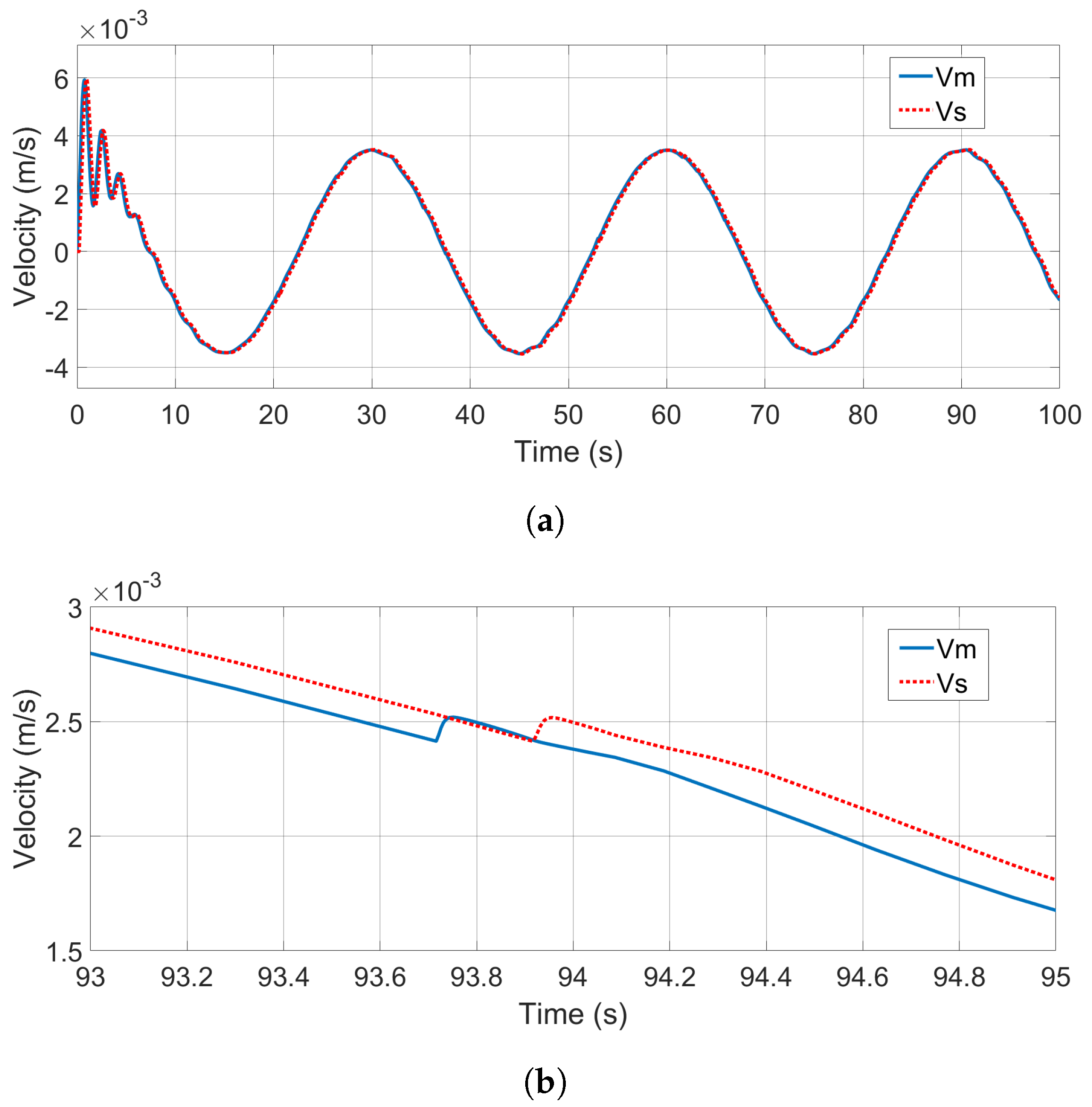
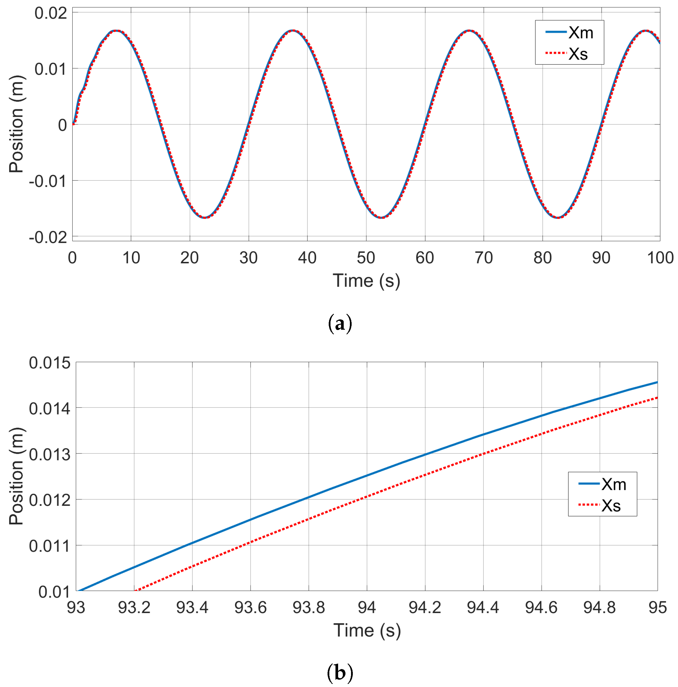
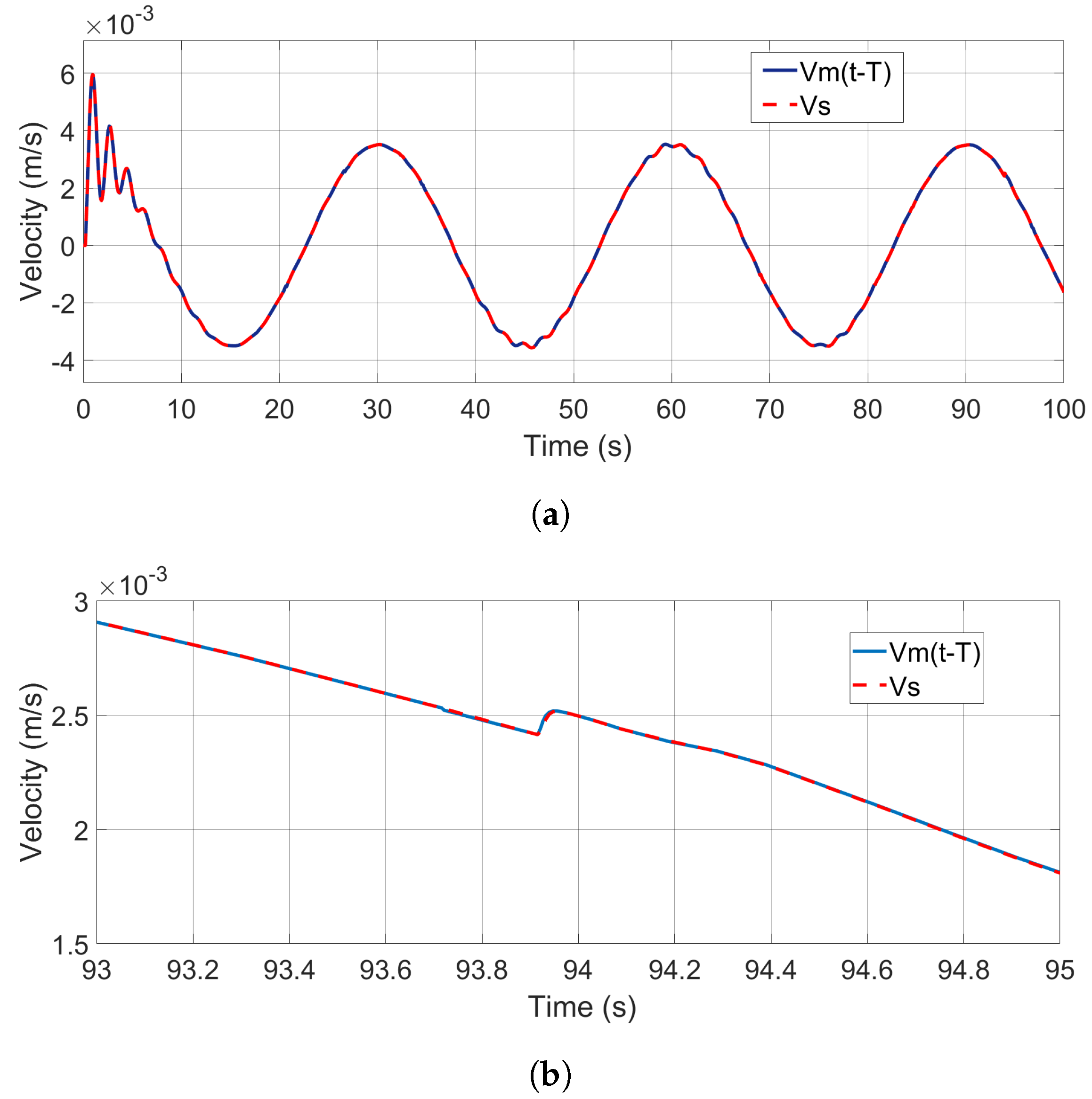
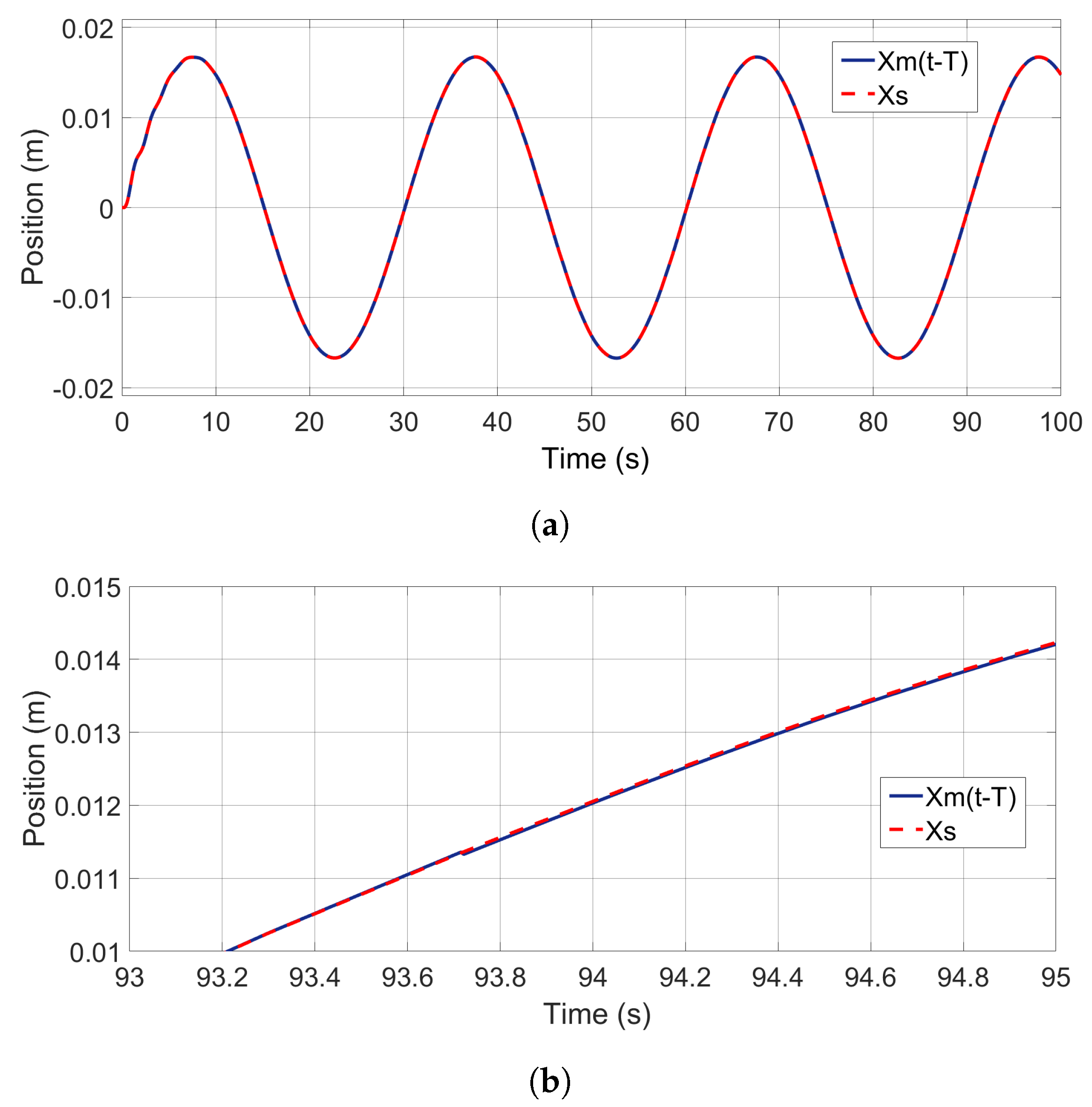
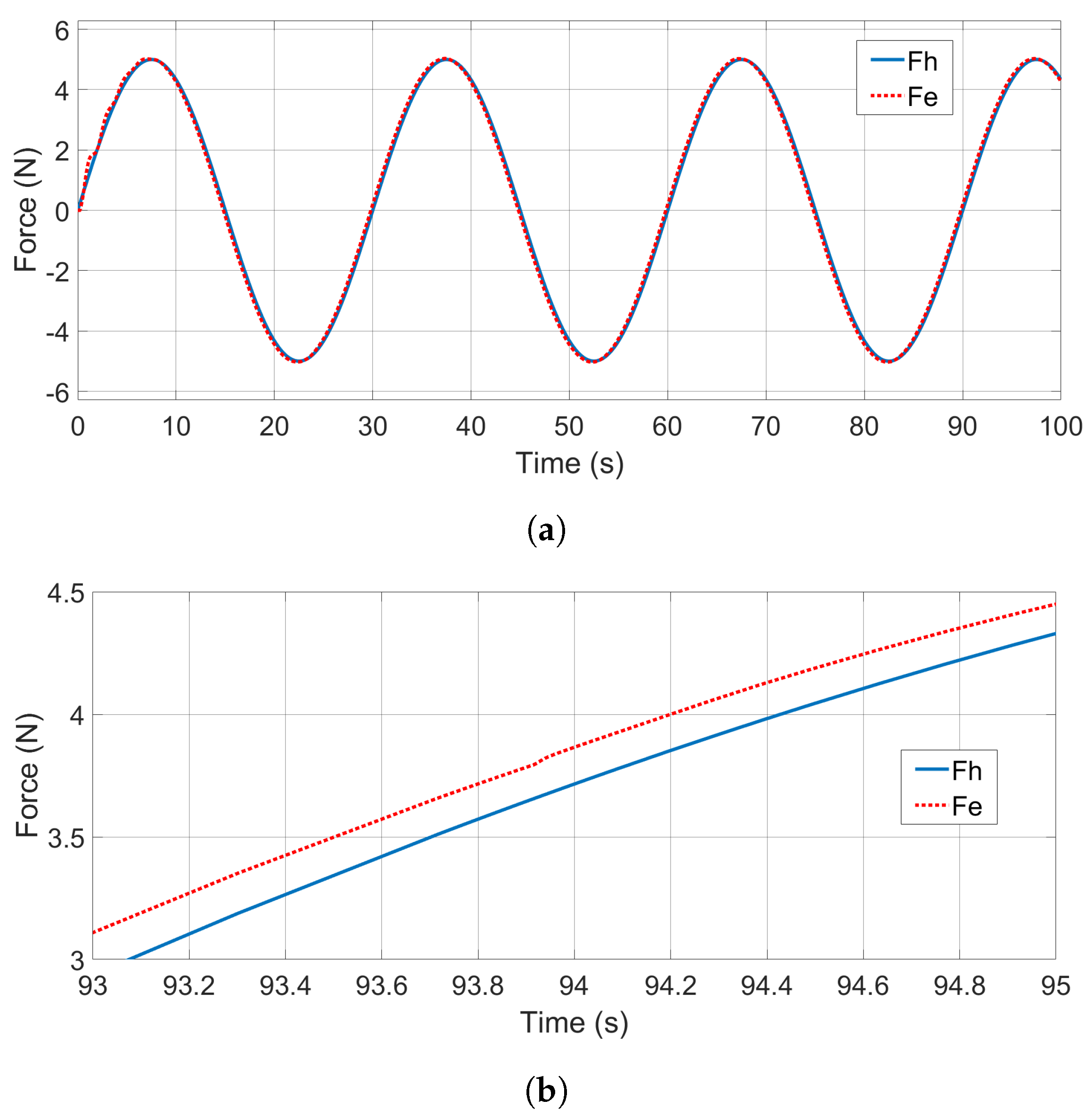
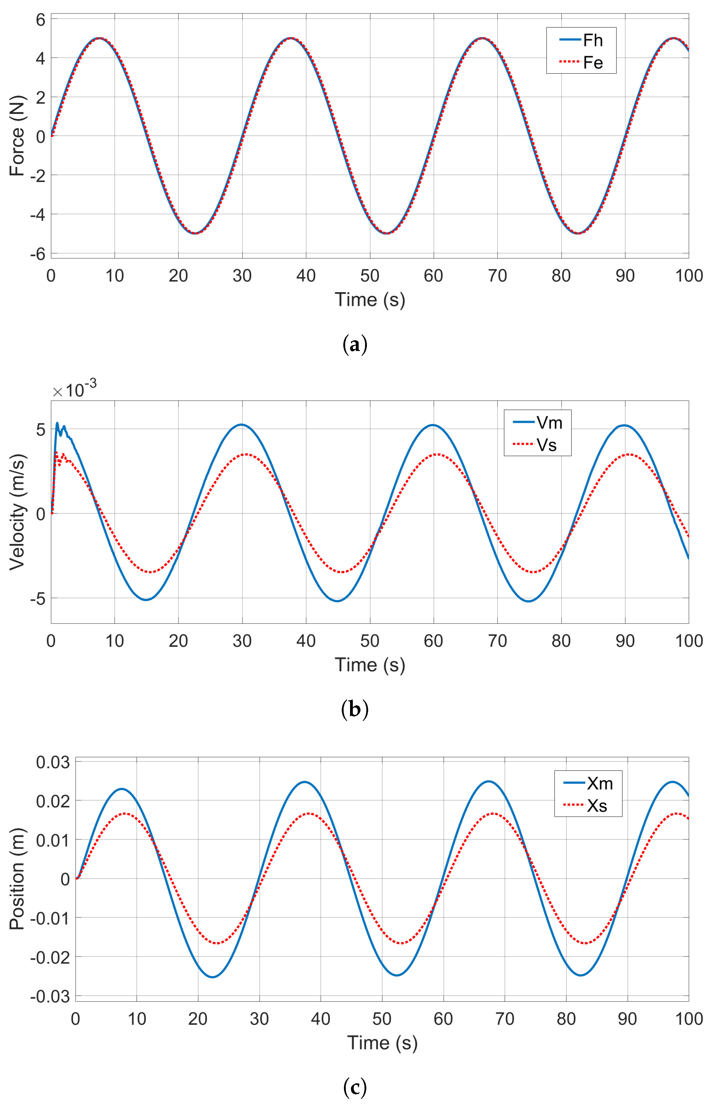
4.2. Results of Wave Variable Compensator-Based 3CH Teleoperation

Through the numerical study, the velocities of the master device and the slave robot ( v m , v s ) can be compared to evaluate their kinematic correspondence. However, the impedance, Z, in the Laplace domain is difficult to plot to illustrate the impedance matching and thus the transparency of the proposed 3CH teleoperation architecture. As an alternative solution, force tracking performance between F h and F e can be studied to evaluate the force correspondence. In the time domain, an equivalent transparency evaluation criterion can be used: “both the position responses x m and x s , and the force responses F h and F e by the operator’s input τ o p (exogenous force F h * ) are identical respectively” [37].
Figure 7a shows the velocity performances of both the master device and the slave robot. As can be seen from this figure, in both transient and steady operation phases, the slave robot velocity tracked closely the one of master device with a constant delay in the phase. The recorded positions of both the master and slave, as shown in Figure 8a, exhibit the same motion-tracking performance.
A careful examination of the tracking performance (93–95 s) finds that the delay in motion tracking is around one single-trip communication delay, T = 200 , ms as can be seen in Figure 7b and Figure 8b, in line with the kinematic correspondence analysis (44). To better illustrate this point, the velocity and position signals of the master device have been shifted backwards by one single trip time (200 ms) and then compared with the signals of the slave robot. The shifted tracking results are shown in Figure 9a and Figure 10a. And the tracking errors after shifting can be seen from Figure 9b and Figure 10b, which show the zoomed-in details of the shifted tracking performances. It can be seen form these figures that the master and slave motion signals after the phase shift are almost identical.
Force-tracking performance, as the other important time domain performance index to evaluate system transparency, has also been studied, with the result shown in Figure 11a. As indicated in the transparency analysis by (45), similar to motion tracking, the operator hand force to the master device F h also showed one round-trip delay ( T = 200 ms) difference in phase from the environment force F e , as can be seen in Figure 11b, which is confirmed by shifting F e by 200 ms, as shown in Figure 12a, with zoomed-in details shown in Figure 12b.
To quantitatively evaluate the tracking performance of the proposed wave variable compensator-based 3CH teleoperation method, we computed three commonly used metrics: the root mean square error (RMSE), the mean absolute error (MAE), and dynamic time warping (DTW). RMSE and MAE were used to assess the average deviation between the master and slave signals for velocity, position, and force tracking, as shown in Table 5. RMSE emphasizes larger errors due to its quadratic nature, while MAE provides a more uniformly weighted error measure, making them complementary for performance evaluation. DTW, on the other hand, was applied to assess the time-aligned similarity between the master and slave trajectories, accounting for slight phase shifts or temporal misalignments. Lower values in all three metrics indicate better tracking fidelity.
When seeing the phase lag T between the slave velocity v s and master velocity v m , and between the hand force to master F h and the environment force F e in the study results, it can be concluded that delay-minimized kinematic and force correspondences are satisfied with the developed 3CH teleoperation structure in the presence of communication time delay, following the definition in [37]. This qualitative observation is further confirmed through quantitative analysis using RMSE, MAE, and DTW metrics. The proposed method exhibits very low tracking errors across velocity, position, and force signals. More notably, after compensating for the single-trip delay via signal shifting, RMSE and MAE values for velocity and position tracking are reduced by over one order of magnitude, while force tracking errors are reduced by at least 39 % compared to the unshifted case. DTW results also show significantly improved trajectory alignment. These findings demonstrate that the proposed wave variable compensator-based design achieves high transparency with minimal delays, making it an effective solution for bilateral teleoperation under communication constraints.

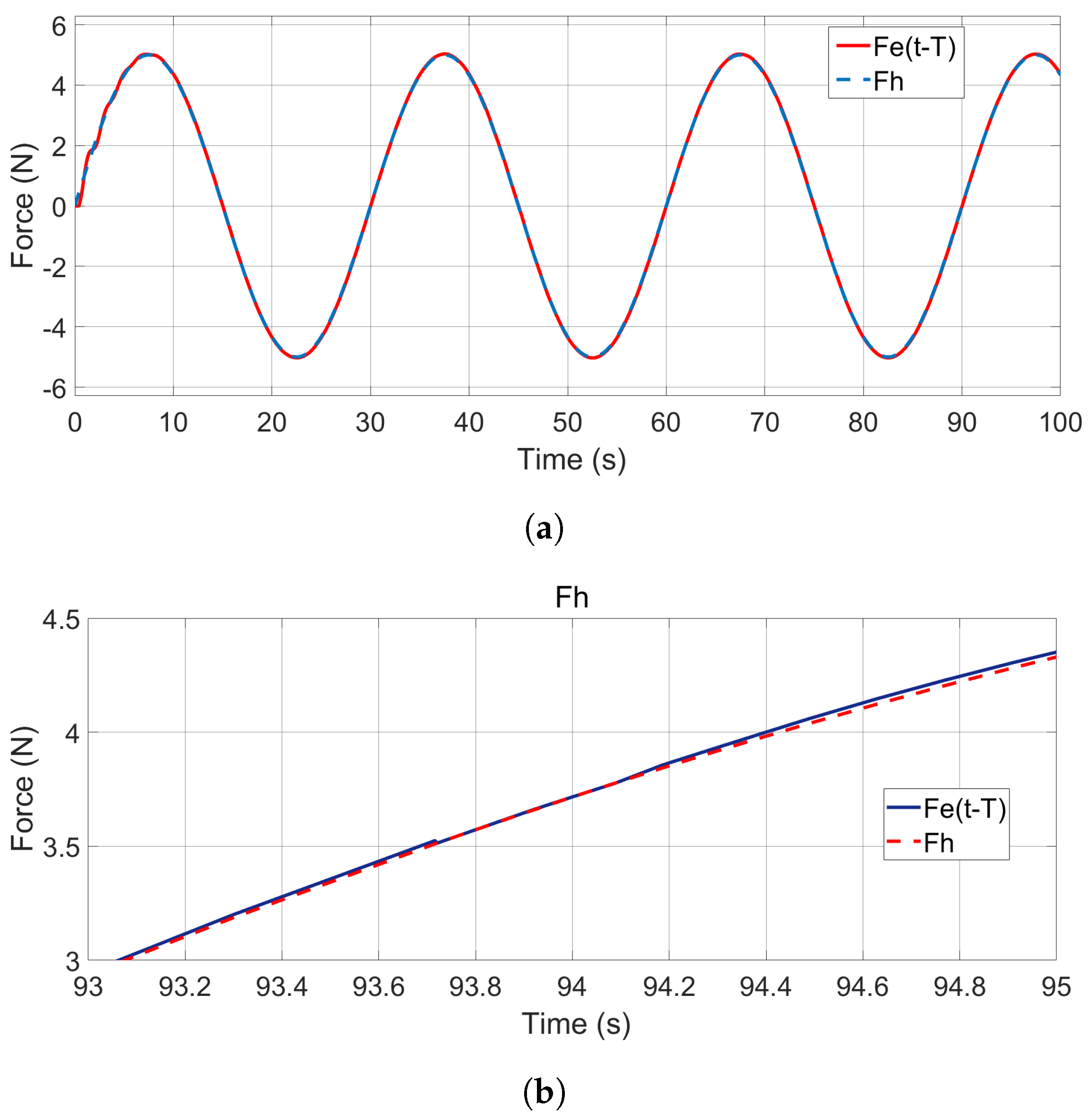
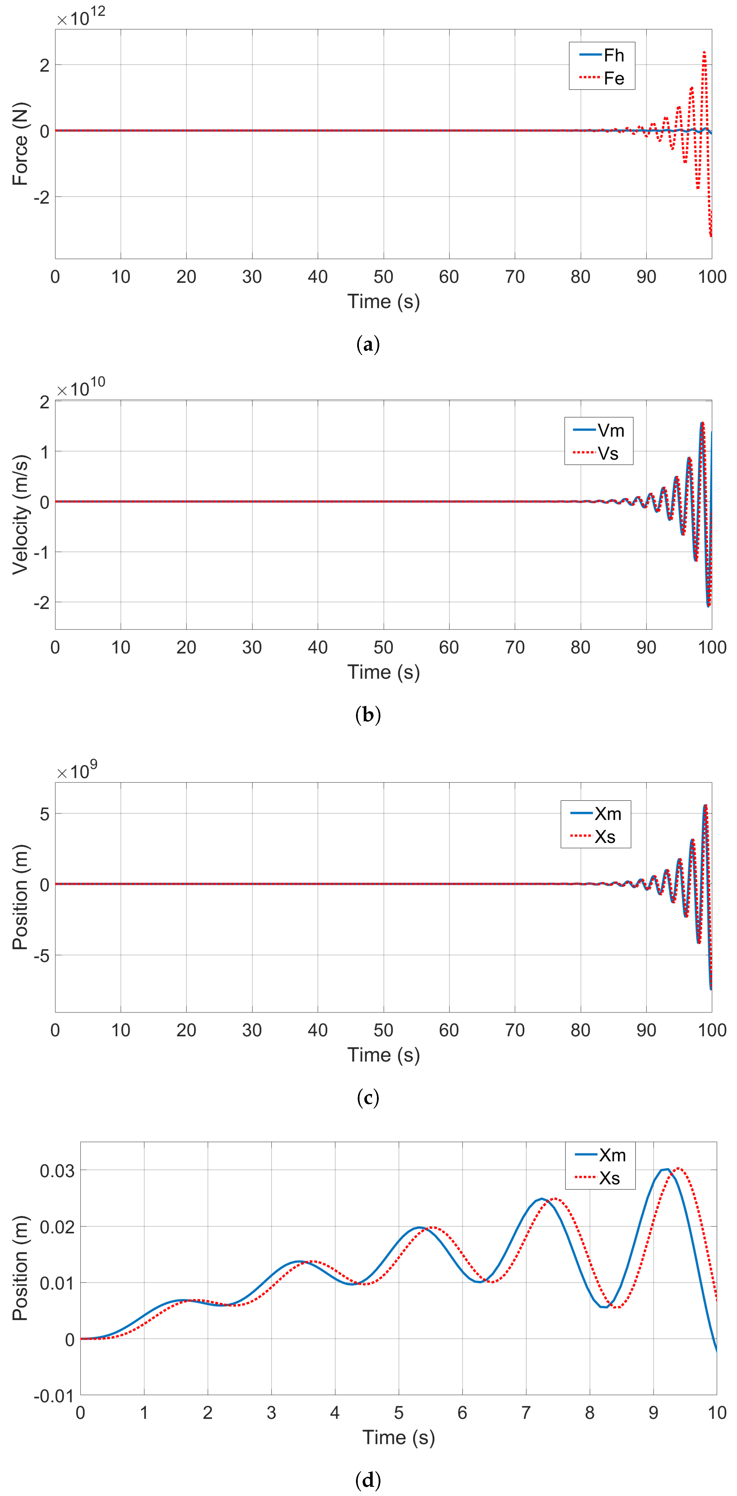
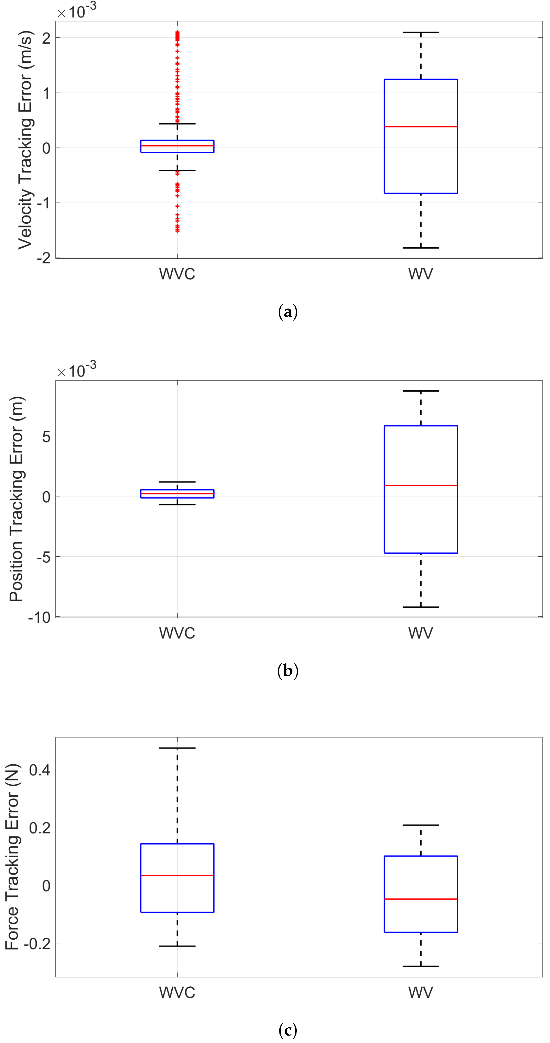
4.3. Results of Comparative Studies

To demonstrate the advantages of the proposed wave variable compensator-based teleoperation structure, numerical studies were also conducted with conventional 3CH teleoperation systems.
Firstly, the reformulated 3CH teleoperation structure using the conventional wave variable technique [31], as shown in Figure 4, was studied. The system setup and the controllers were chosen to be identical to that in the first study, and the obtained system performances are illustrated in Figure 13. The results show that the teleoperation system remained stable with the presence of communication delays. However, despite the similar force responses shown in Figure 13a, both velocity- and position-tracking performances showed considerable mismatches, as can be seen in Figure 13b,c. The motion-tracking mismatches can be explained by the direct implementation of conventional wave variable technique and consequently its inherent drawback of bias in the transmitted signals, as shown in Equations (12) and (13). In this situation, the system transparency was significantly degraded.
Then, the directly connected 3CH teleoperation structure, as shown in Figure 2, was studied with the same system setup and the controller configurations, and the system performances are shown in Figure 14. It is seen that the teleoperation system became unstable, which is consistent with the theoretical analysis and practical observation that time delays in direct power signals (velocity, position, and force) transmission cause instability of bilateral teleoperation systems. Figure 14d clearly demonstrates that the systems exhibited tendency of instability from the very beginning.
In addition to the qualitative time-domain comparisons, we also performed a quantitative analysis of the tracking performance for the conventional wave variable-based 3CH teleoperation method [31] using the RMSE, MAE, and DTW metrics, as shown in Table 6. These evaluations were conducted on the same velocity, position, and force signals used for the proposed method in the previous section, Section 4.2. For the direct signal-connected 3CH structure, which exhibited instability from the beginning of the simulation, such a quantitative analysis was not meaningful and was, therefore, omitted. The results show that our proposed wave variable compensator-based method achieves significantly lower RMSE and MAE values for both velocity and position tracking compared to the conventional wave variable approach. While the force-tracking errors between the two methods are relatively close, the DTW value for our proposed method is notably lower, indicating better temporal alignment and improved perceived transparency. To statistically validate these differences, we conducted Mann–Whitney U tests on the tracking error distributions. The results yielded very low p-values for velocity−tracking error ( p = 0.0039 0.05 ) and position−tracking error ( p = 3.0691 × 10 6 0.05 ), as shown in Figure 15a and Figure 15b, respectively, confirming a statistically significant improvement in motion-tracking performance of the proposed method over wave variable-based method under comparison. In contrast, the p-value for force-tracking errors was 1, as shown in Figure 15c, indicating no significant difference in force tracking accuracy between the two methods. However, the lower DTW value obtained for the proposed method suggests better temporal alignment of the force signals. This highlights that, beyond point-wise error magnitude, the proposed method improves the overall shape fidelity and responsiveness of force feedback, which represents an essential aspect of perceived transparency in teleoperation.
The comparative studies confirm that the proposed wave variable compensator-based approach not only eliminates the risk of instability caused by communication delays but also significantly enhances the kinematic correspondence and improves the overall transparency of the 3CH teleoperation system compared to conventional methods. Quantitative results based on the RMSE, MAE, and DTW metrics demonstrate substantial reductions in velocity- and position-tracking errors, with statistical significance supported by low p-values from the Mann–Whitney U test. Although the force-tracking errors are similar in magnitude to those of the conventional wave variable-based method, the lower DTW value achieved by the proposed method indicates better temporal alignment and more consistent force feedback. As a result, the proposed approach not only guarantees stability under time delay but also delivers high-fidelity motion and force tracking, leading to improved transparency in bilateral teleoperation.

5. Conclusions

In this paper, we have proposed a novel three-channel teleoperation structure employing wave variable compensators to achieve delay-minimized transparency and guaranteed system passivity in the presence of communication delay. The key contributions of this work include the reformulation of the three-channel teleoperation into a two-channel-like architecture, the introduction of two wave variable compensators to significantly reduce transmission biases inherent in conventional wave variable methods, and the implementation of energy reservoirs to rigorously maintain overall system passivity. Numerical simulation studies confirmed that the proposed approach substantially improves both kinematic and force tracking performances compared with conventional wave variable techniques. Specifically, quantitative evaluations demonstrated reductions in tracking errors, with the root mean square error (RMSE) improved by at least 54.8% and the mean absolute error (MAE) improved by at least 76.7% for velocity and position tracking. Dynamic time warping (DTW) analyses further illustrated enhanced similarity between master and slave trajectories, especially in force tracking. The statistical significance of these improvements was validated using the Mann–Whitney U test, clearly indicating superior performance of the proposed method over conventional approaches.
Despite these promising results, the current study faced certain limitations, notably the absence of experimental validation and potential sensitivity of the proposed method to variations in hardware implementation. To address these limitations, our immediate next step is to implement the proposed method on a physical teleoperation setup. Moreover, while the proposed method has shown strong performance in simulations, we recognize that physical implementation in teleoperation systems, e.g., medical applications such as telesurgery, introduces additional challenges not fully captured in numerical studies. These include potential deviations due to sensor noise, actuator latency, and communication jitter, as well as practical constraints such as limited onboard computational resources and real-time safety requirements. To address these concerns, we plan to apply filtering and signal pre-processing to reduce noise, enforce safety thresholds in haptic feedback, and optimize the control implementation for execution on embedded or real-time platforms. A hardware-in-the-loop (HIL) simulation setup is currently under development to serve as an intermediate step before the method is deployed on physical robotic systems. This platform will allow us to evaluate robustness, responsiveness, and transparency under realistic operating conditions while ensuring safety and controllability. Subsequent full-scale experiments will then validate performance improvements demonstrated through our simulation results and confirm practical feasibility in real-world conditions, especially medical applications like teleoperated needle insertion tasks.
Future research will also extend the proposed wave variable compensator method to additional teleoperation configurations beyond the P–PF structure investigated in this paper. Moreover, the current study considered only constant communication delays, and future studies will explore robustness of the proposed method under time-varying or stochastic delay conditions. These efforts aim to enhance the generalizability and applicability of our approach to practical teleoperation scenarios for delicate tasks in medical teleoperation such as robotic-assisted surgery and remote medical diagnostics.

Author Contributions

Conceptualization, C.L.; investigation, B.Y.; methodology, B.Y.; software, J.T. and S.X.; supervision, C.L.; validation, L.Z.; writing—original draft, B.Y.; writing—review and editing, L.T. and W.Z. All authors have read and agreed to the published version of the manuscript.

Funding

This research was partially funded by the Pole Universitaire d’Innovation de Montpellier, University of Montpellier under the “Companies and Campus” project INTELLISHARE.

Data Availability Statement

The original contributions presented in this study are included in the article. Further inquiries can be directed to the corresponding author.

Conflicts of Interest

Author Lei Zhang was employed by the company euroDAO SAS. The remaining authors declare that the research was conducted in the absence of any commercial or financial relationships that could be construed as a potential conflict of interest.

References

  1. Goertz, R.C. Master-Slave Manipulator; Argonne National Laboratory: Lemont, IL, USA, 1949; Volume 2635. [Google Scholar]
  2. Nakjima, Y.; Nozaki, T.; Ohnishi, K. Heartbeat synchronization with haptic feedback for telesurgical robot. IEEE Trans. Ind. Electron. 2014, 61, 3753–3764. [Google Scholar] [CrossRef]
  3. Wen, H.; Cong, M. Kinematic model and analysis of an actuation redundant parallel robot with higher kinematic pairs for jaw movement. IEEE Trans. Ind. Electron. 2015, 62, 1590–1598. [Google Scholar] [CrossRef]
  4. Deng, Z.; Stommel, M.; Xu, W. A novel soft machine table for manipulation of delicate objects inspired by caterpillar locomotion. IEEE/ASME Trans. Mechatronics 2016, 21, 1702–1710. [Google Scholar] [CrossRef]
  5. Wang, D.; Zhao, X.; Shi, Y.; Zhang, Y.; Xiao, J. Six degree-offreedom haptic simulation of a stringed musical instrument for triggering sounds. IEEE Trans. Haptics 2017, 10, 265–275. [Google Scholar] [CrossRef] [PubMed]
  6. Lawrence, D.A. Stability and transparency in bilateral teleoperation. IEEE Trans. Robot. Autom. 1993, 9, 624–637. [Google Scholar] [CrossRef]
  7. Anderson, R.J.; Spong, M.W. Bilateral control of teleoperators with time delay. IEEE Trans. Autom. Control 1989, 34, 494–501. [Google Scholar] [CrossRef]
  8. Niemeyer, G.; Slotine, J.J.E. Stable adaptive teleoperation. IEEE J. Ocean. Eng. 1991, 16, 152–162. [Google Scholar] [CrossRef]
  9. Alise, M.; Roberts, R.G.; Repperger, D.W.; Moore, C.A.; Tosunoglu, S. On Extending the Wave Variable Method to Multiple-DOF Teleoperation Systems. IEEE/ASME Trans. Mechatron. 2009, 14, 55–63. [Google Scholar] [CrossRef]
  10. Polushin, I. A Generalized Scattering Framework for Teleoperation with Communication Delays. IFAC-PapersOnLine 2020, 53, 10064–10069. [Google Scholar] [CrossRef]
  11. Najafabadi, A.M.; Ataei, M.; Motaharifar, M. Disturbance Observer Based Synchronization Controtl for Passive Bilateral Teleoperation Systems with Time Delays. In Proceedings of the 10th RSI International Conference on Robotics and Mechatronics, Tehran, Iran, 15–18 November 2022; pp. 610–615. [Google Scholar]
  12. Ghavifekr, A.A.; Ghiasi, A.R.; Badamchizadeh, M.A. Discrete-time control of bilateral teleoperation systems: A review. Robotica 2018, 36, 552–569. [Google Scholar] [CrossRef]
  13. Yoo, S.G.; Chong, K.T. Adaptive wave variables for bilateral teleoperation using neural networks. Neural Comput. Appl. 2014, 25, 1249–1262. [Google Scholar] [CrossRef]
  14. Jafari, B.H.; Spong, M.W. Passivity-based switching control in teleoperation systems with time-varying communication delay. In Proceedings of the American Control Conference (ACC), Seattle, WA, USA, 24–26 May 2017; pp. 5469–5475. [Google Scholar]
  15. Hader, A.; El-Kasri, C.; Tissir, E.; Alfidi, M. Improved Stability and Performance Criteria for Teleoperation Delay-Dependent Systems: SSG and Input–output Approaches. Circuits Syst. Signal Process. 2023, 42, 5187–5206. [Google Scholar] [CrossRef]
  16. Chan, L.; Liu, Y.; Huang, Q.; Wang, P. Robust Adaptive Observer-Based Predictive Control for a Non-Linear Delayed Bilateral Teleoperation System. IEEE Access 2022, 10, 52294–52305. [Google Scholar] [CrossRef]
  17. Chang, Y.-H.; Yang, C.-Y.; Lin, H.-W. Robust Adaptive-Sliding-Mode Control for Teleoperation Systems with Time-Varying Delays and Uncertainties. Robotics 2024, 13, 89. [Google Scholar] [CrossRef]
  18. Zhou, X.; Bai, W.; Ren, Y.; Yang, Z.; Wang, Z.; Lo, B.; Yeatman, E.M. An LSTM-based Bilateral Active Estimation Model for Robotic Teleoperation with Varying Time Delay. In Proceedings of the International Conference on Advanced Robotics and Mechatronics (ICARM), Guilin, China, 9–11 July 2022; pp. 725–730. [Google Scholar]
  19. Zhang, S.; Yuan, S.; Yu, X.; Kong, L.; Li, Q.; Li, G. Adaptive Neural Network Fixed-Time Control Design for Bilateral Teleoperation with Time Delay. IEEE Trans. Cybern. 2022, 52, 9756–9769. [Google Scholar] [CrossRef] [PubMed]
  20. Dao, P.N.; Nguyen, V.Q.; Duc, H.A.N. Nonlinear RISE based integral reinforcement learning algorithms for perturbed Bilateral Teleoperators with variable time delay. Neurocomputing 2024, 605, 128355. [Google Scholar] [CrossRef]
  21. Dao, P.N.; Nguyen, Q.P.; Vu, M.H. Adaptive optimal coordination control of perturbed Bilateral Teleoperators with variable time delays using Actor–Critic Reinforcement Learning algorithm. Math. Comput. Simul. 2025, 229, 151–175. [Google Scholar] [CrossRef]
  22. Coelho, A.; Singh, H.; Muskardin, T.; Balachandran, R.; Kondak, K. Smoother Position-Drift Compensation for Time Domain Passivity Approach Based Teleoperation. In Proceedings of the IEEE/RSJ International Conference on Intelligent Robots and Systems, Madrid, Spain, 1–5 October 2018; pp. 5525–5532. [Google Scholar]
  23. Yalcin, B.; Ohnishi, K. Stable and Transparent Time-Delayed Teleoperation by Direct Acceleration Waves. IEEE Trans. Ind. Electron. 2010, 57, 3228–3238. [Google Scholar] [CrossRef]
  24. Chen, Z.; Huang, F.; Sun, W.; Yang, C.; Song, W.; Wang, T.; Zhu, S. A novel wave variable based bilateral teleoperation control design for transparency improvement. In Proceedings of the IEEE International Conference on Information and Automation, Wuyishan, China, 11–13 August 2018; pp. 1–6. [Google Scholar]
  25. Balachandran, R. Transparency Enhancement in Teleoperation. In A Stable and Transparent Framework for Adaptive Shared Control of Robots; Springer Tracts in Advanced Robotics; Springer: Berlin/Heidelberg, Germany, 2024; Volume 158. [Google Scholar]
  26. Hashtrudi-Zaad, K.; Salcudean, S.E. Transparency in time-delayed systems and the effect of local force feedback for transparent teleoperation. IEEE Trans. Robot. Autom. 2002, 18, 108–114. [Google Scholar] [CrossRef]
  27. Uyulan, C. Robust passivity-based nonlinear controller design for bilateral teleoperation system under variable time delay and variable load disturbance. Nonlinear Eng. 2024, 13, 20220358. [Google Scholar] [CrossRef]
  28. Farajiparvar, P.; Mahjoob, M.; Towhidkhah, F.; Shoham, M. A brief survey of telerobotic time delay mitigation. Front. Robot. AI 2020, 7, 577768. [Google Scholar] [CrossRef] [PubMed]
  29. Risiglione, M.; Sleiman, J.-P.; Minniti, M.V.; Çizmeci, B.; Dresscher, D.; Hutter, M. Passivity-based control for haptic teleoperation of a legged manipulator in presence of time-delays. In Proceedings of the IEEE/RSJ International Conference on Intelligent Robots and Systems (IROS), Prague, Czech Republic, 27 September–1 October 2021; pp. 5276–5281. [Google Scholar]
  30. Albakri, A.; Liu, C.; Poignet, P. Stability and performance analysis of three-channel teleoperation control architectures for medical applications. In Proceedings of the IEEE/RSJ International Conference on Intelligent Robots and Systems (IROS), Tokyo, Japan, 3–7 November 2013. [Google Scholar]
  31. Aziminejad, A.; Tavakoli, M.; Patel, R.V.; Moallem, M. Transparent time-delayed bilateral teleoperation using wave variables. IEEE Trans. Control Syst. Technol. 2008, 16, 548–555. [Google Scholar] [CrossRef]
  32. Guo, J.; Liu, C.; Poignet, P. Scaled position-force tracking for wireless teleoperation of miniaturized surgical robotic system. In Proceedings of the 36th Annual International Conference of the IEEE Engineering in Medicine and Biology Society, Chicago, IL, USA, 26–30 August 2014; pp. 361–365. [Google Scholar]
  33. Lam, T.M.; Mulder, M.; van Paassen, M.M. Haptic Feedback in Uninhabited Aerial Vehicle Teleoperation with Time Delay. J. Guid. Control Dyn. 2008, 31, 1728–1739. [Google Scholar] [CrossRef]
  34. Mirfakhrai, T.; Payandeh, S. A delay prediction approach for teleoperation over the Internet. In Proceedings of the 2002 IEEE International Conference on Robotics and Automation (ICRA), Washington, DC, USA, 11–15 May 2002; Volume 2, pp. 2178–2183. [Google Scholar]
  35. Chen, Y.; Hunter, I.W. Nonlinear stochastic system identification of skin using Volterra kernels. Ann. Biomed. Eng. 2013, 41, 847–862. [Google Scholar] [CrossRef]
  36. Parker, M.D.; Jones, L.A.; Hunter, I.W.; Taberner, A.J.; Nash, N.P.; Nielsen, P.M. Multidirectional In Vivo Characterization of Skin Using Wiener Nonlinear Stochastic System Identification Techniques. J. Biomech. Eng. 2017, 139, 011002. [Google Scholar] [CrossRef] [PubMed]
  37. Yokokohji, Y.; Yoshikawa, T. Bilateral control of master-slave manipulators for ideal kinesthetic coupling. IEEE Trans. Robot. Autom. 1994, 10, 605–620. [Google Scholar] [CrossRef]
Figure 1. Four-channel teleoperation structure with time delay [26].
Electronics 14 02595 g001
Figure 2. P-PF 3CH teleoperation structure.
Electronics 14 02595 g002
Figure 3. Standard wave variable formulation.
Electronics 14 02595 g003
Figure 4. The reformulated P-PF teleoperation structure.
Electronics 14 02595 g004
Figure 5. The modified wave variable structure with compensators.
Electronics 14 02595 g005
Figure 6. Equivalent structure.
Electronics 14 02595 g006
Figure 7. Velocity−tracking performance. (a) Overall velocity—tracking performance. (b) Zoomed—in tracking performance (93−95 s).
Electronics 14 02595 g007
Figure 8. Position—tracking performance. (a) Overall position—tracking performance. (b) Zoomed−in tracking performance (93−95 s).
Electronics 14 02595 g008
Figure 9. Shifted velocity—tracking performance. (a) Velocity—tracking with shifted V m ( t T ) . (b) Zoomed—in shifted tracking performance.
Electronics 14 02595 g009
Figure 10. Shifted position—tracking performance. (a) Position—tracking with shifted X m ( t T ) . (b) Zoomed—in shifted tracking performance.
Electronics 14 02595 g010
Figure 11. Force responses. (a) Overall force responses. (b) Zoomed—in force responses.
Electronics 14 02595 g011
Figure 12. Shifted force responses. (a) Force responses with shifted F e ( t T ) . (b) Zoomed—in shifted force responses.
Electronics 14 02595 g012
Figure 13. Wave variable reformulated 3CH teleoperation. (a) Force responses. (b) Velocity—tracking performance. (c) Position—tracking performance.
Electronics 14 02595 g013
Figure 14. Directly connected 3CH teleoperation. (a) Force responses. (b) Velocity—tracking performance. (c) Position—tracking performance. (d) Zoomed—in position-tracking performance (0–10 s).
Electronics 14 02595 g014
Figure 15. Statistical performance difference analysis using Mann—Whitney U test. (a) Velocity—tracking errors: p = 0.0039 0.05 . (b) Position—tracking errors: p = 3.0691 × 10 6 0.05 . (c) Force—tracking errors: p = 1 > 0.05 .
Electronics 14 02595 g015
Table 1. List of abbreviations.
AbbreviationDescription
3CHThree-Channel Teleoperation
4CHFour-Channel Teleoperation
2CHTwo-Channel Teleoperation
P–PFPosition–Position Force control structure
F–PFForce–Position Force control structure
PF–PPosition Force–Position control structure
PF–FPosition Force–Force control structure
WVCWave Variable Compensator
WVWave Variable
HILHardware-in-the-Loop
RMSERoot Mean Square Error
MAEMean Absolute Error
DTWDynamic Time Warping
DOFDegree of Freedom
OROperating Room
PRCPassive Reference Coupling
RLReinforcement Learning
LSTMLong Short-Term Memory
BAEMBilateral Active Estimation Model
RBFNNsRadial Basis Function Neural Networks
PIDProportional–Integral–Derivative controller
Table 2. Summary of controller design steps for the proposed 3CH teleoperation system.
StepDescriptionKey Equations
1Select 3CH configuration (e.g., P–PF) and define master/slave signalsBased on system setup (Section 2)
2Reformulate system as two-port network using exchanged velocity and force signalsEquations (10)–(12)
3Apply wave variable transformation to encode transmitted signalsEquation (13)
4Design wave variable compensator using delayed local variablesEquations (17)–(21)
5Define energy reservoir functions to accumulate compensation-induced energyEquation (22)
6Modulate compensator terms using reservoir-dependent exponential scalingEquation (24)
7Analyze system transparency under delay and assess tracking qualityEquations (25)–(27)
Table 3. Simulation parameters.
ParameterValueUnit
α 1
β 1
E m ( 0 ) 6000J
E s ( 0 ) 6000J
M m , M s 1kg
k e 300N/m
b e 10N· s/m
Table 4. Controller design.
ControllerExpression
C m 100 + 10/s
C s 100 + 10 s + 10/s
C 1 Z s + C s
C 2 2
C 3 0
C 4 Z m C m
C 6 1
C 5 −1
Table 5. Quantitative analysis of motion- and force-tracking errors.
v m , v s x m , x s F e , F h v m ( t T ) , v s x m ( t T ) , x s F e ( t T ) , F h
RMSE 5.4173 × 10 4 4.7875 × 10 4 0.1476 1.0075 × 10 5 1.2209 × 10 5 0.0892
MAE 2.5623 × 10 4 4.0856 × 10 4 0.1293 5.1280 × 10 6 9.4375 × 10 6 0.0451
DTW0.02410.091615.76460.00320.006110.6624
Table 6. Quantitative comparison between the proposed and conventional methods.
Proposed WVC MethodConventional WV Method [31]
v m , v s x m , x s F e , F h v m , v s x m , x s F e , F h
RMSE 5.4173 × 10 4 4.7875 × 10 4 0.14760.00120.00580.1444
MAE 2.5623 × 10 4 4.0856 × 10 4 0.12930.00110.00490.1210
DTW0.02410.091615.76460.30841.654129.9781
Disclaimer/Publisher’s Note: The statements, opinions and data contained in all publications are solely those of the individual author(s) and contributor(s) and not of MDPI and/or the editor(s). MDPI and/or the editor(s) disclaim responsibility for any injury to people or property resulting from any ideas, methods, instructions or products referred to in the content.

