Abstract
This paper presents an analytical study of the bit error rate (BER) and signal-to-noise ratio (SNR) performance in simultaneous wireless information and power transfer (SWIPT) amplify-and-forward (AF) relaying systems over Rayleigh fading channels. A power-splitting (PS) protocol is employed at the energy-constrained relay to divide the received signal for concurrent energy harvesting and information processing. Closed-form and asymptotic BER expressions are derived based on exact and bounded moment-generating functions (MGFs), offering insights into how the SNR balance between the source–relay (SR) and relay–destination (RD) links influences system performance. An asymptotic BER expression further reveals that a SWIPT AF relay system can be interpreted as a generalized AF relaying model, sharing the same diversity order as conventional AF systems. Based on this interpretation, an optimization method for the PS factor is proposed, effectively reducing the BER by reinforcing the weaker link. Simulation results confirm the tightness of the derived expressions and the effectiveness of the optimization strategy. Moreover, the analytical framework is extended to multiple SWIPT relaying systems, where multiple relays operate with individually optimized PS ratios. For such configurations, approximations for the system BER, outage probability, and channel capacity are derived and validated. Results demonstrate that increasing the number of relays significantly improves system performance, and the proposed analysis accurately captures these performance gains under varying channel conditions.
1. Introduction
In next-generation wireless communication systems, energy supply has emerged as one of the most critical challenges [1]. Among various energy supply and harvesting techniques, utilizing received radio frequency (RF) signals that simultaneously carry information and energy has gained significant attention. To exploit the far-field energy of RF signals, energy harvesting (EH)-enabled communication has been extensively studied over the past decade. In particular, two prominent models have been widely investigated: the simultaneous wireless information and power transfer (SWIPT) model, where a transmitter concurrently delivers information and energy signals to both information and EH receivers [1,2,3], and the wireless powered communication network (WPCN) model, where all transmitting nodes are powered by RF energy broadcast from a dedicated energy beacon [4,5,6,7,8]. These models offer practical and scalable solutions for sustainable wireless networks [9,10].
Meanwhile, relay-based communication schemes have been extensively studied due to their simple operation, ability to extend cell coverage, and capability to enhance communication reliability [11,12,13,14]. Early research on relay systems typically assumed that relays were equipped with dedicated power supplies [15,16,17,18,19,20,21,22,23,24]. However, recent efforts have shifted toward the development of SWIPT-enabled relays, where relays forward received information signals using energy harvested from incoming RF signals. This approach can significantly prolong relay battery lifespan and enables the deployment of relays without built-in power sources. Furthermore, recent advancements in the practical implementation of EH hardware have enhanced the feasibility and applicability of SWIPT-based systems [25,26].
Depending on how the information decoding and EH processes are separated, SWIPT relays can adopt one of two practical receiver architectures: power splitting (PS) and time switching (TS) [1,27,28]. In the TS architecture, dedicated time slots are allocated separately for EH and information decoding. In contrast, the PS architecture divides the received signal power into two streams—one for EH and the other for information processing (IP). Among these, the PS receiver is more commonly employed in SWIPT relay systems, as TS requires accurate time synchronization and may cause interruptions in subsequent data transmission [5,6,8].
An effective approach to understanding a communication system is through analytical performance evaluation using mathematical models. For conventional non-SWIPT relaying systems, extensive analytical results have been reported in the literature [15,16,17,18,19,20,21,23,24]. In [27], the authors analyzed the performance of a SWIPT amplify-and-forward (AF) relaying scheme with a PS receiver, focusing on the outage probability of the achievable information rate. This work was later extended to more generalized scenarios, including the presence of a direct link between the source and destination [28], and the case of correlated Nakagami-m fading using copula theory [29]. Additionally, the performance of flipped SWIPT relay systems, where an energy-constrained source is powered by nearby relays, was studied in [30]. The bit error rate (BER) performance of WPCN-like AF relaying systems, where both the source and the relay are powered by an external energy beacon, was investigated in [31].
In [32,33], exact closed-form expressions for the BER were derived for SWIPT AF relaying networks employing differential modulation over Rayleigh fading channels. The work in [34] analyzed the average BER and outage probability performance of SWIPT cooperative AF relaying systems with both binary phase shift keying (BPSK) and differential BPSK under composite Nakagami-lognormal fading conditions. In [35], the average BER performance of dual-hop SWIPT AF and decode-and-forward (DF) relaying systems over Nakagami-m fading channels was investigated. The average error rate of SWIPT DF relaying systems was further studied in [36]. However, the resulting error expressions in these studies are mathematically complex and lack analytical tractability, making it difficult to evaluate cooperative diversity performance based on the derived BER. In the context of multi-antenna cooperative cognitive radio networks supporting Device-to-Device (D2D) communications, a comparative performance analysis of DF and AF relaying in SWIPT-enabled systems was conducted in [37]. This study derived closed-form outage probability expressions and demonstrated that DF relaying achieves better energy efficiency at low transmit power, while AF relaying outperforms DF at high transmit power. Moreover, ref. [38] analyzed the outage performance of a full-duplex two-way DF relay network, enabled by SWIPT, under the combined impact of residual hardware impairments and residual self-interference, revealing a system performance ceiling effect beyond which reliable communication is no longer feasible regardless of the signal-to-noise ratio (SNR). Additionally, ref. [29] studied the impact of fading channel correlation on dual-hop DF SWIPT relay networks using a power splitting-based relaying protocol. The authors derived closed-form expressions for ergodic capacity and outage probability under correlated Nakagami-m fading using copula theory, demonstrating that positive dependence between the source–relay and relay–destination links significantly enhances system performance compared to negative or independent fading scenarios. Furthermore, the AF-SWIPT source power minimization problem for multi-hop cooperative relaying was formulated in [39]. Despite these advancements, to the best of our knowledge, a tractable analytical framework that interprets the SWIPT-AF relay system as an equivalent non-SWIPT (i.e., power-supplied) AF relay system has not yet been proposed. It is also noteworthy that most prior studies on power-splitting factor (PSF) optimization primarily focused on outage probability or transmit power minimization, rather than BER performance [28,29,37,38,39].
In this paper, we provide a comprehensive analytical framework for evaluating the performance of SWIPT AF relaying systems, including the extension to multiple relays. The main contributions are as follows:
- Exact and Upper-Bound BER Expressions: We derive exact and upper-bound BER expressions for SWIPT AF relaying systems under Rayleigh fading using the MGF-based approach.
- Closed-Form Asymptotic BER and SNR Interpretation: An intuitive asymptotic BER expression is presented, revealing the harmonic-mean interpretation of the end-to-end SNR, similar to conventional non-SWIPT AF systems.
- PS Factor Optimization: Based on the derived asymptotic BER, we propose an efficient PS optimization method that enhances BER performance while significantly reducing search complexity.
- Extension to Multiple SWIPT Relays: The proposed framework is extended to a multiple-relay SWIPT system, and its performance is analyzed in terms of BER, outage probability, and channel capacity under different relay configurations and channel conditions.
- Unified Analytical Bound: For the multiple-relay scenario, we derive approximated but tractable analytical expressions that capture the overall performance trend and validate their accuracy through simulation.
- Simulation Validation: Extensive simulations confirm the validity of the proposed analysis and demonstrate the impact of the number of relays and optimized PS factors on system performance.
The rest of this paper is organized as follows. Section 2 describes the system model of the SWIPT AF relaying system. Section 3 derives the analytical BER expressions and PS optimization. In Section 4, we extend the analysis to the multiple SWIPT relay scenario and derive performance bounds. Section 5 presents simulation results, and concluding remarks are given in Section 6.
2. System Model
We consider a point-to-point wireless communication system in which a cooperative relay assists in transmitting data from the source to the destination. An AF relay operating in half-duplex mode is employed, and all nodes—including the source, relay, and destination—are assumed to be equipped with a single antenna. The relay node is considered energy-constrained and lacks a dedicated power supply. Instead, it operates by harvesting energy from the RF signal transmitted by the source. To enable simultaneous EH and IP at the relay, a PS receiver architecture is adopted. Specifically, the received signal power at the relay is split into two parts: one portion is used for EH, and the remaining portion is used for IP, as in [27,28].
2.1. Single SWIPT Relaying System Model
From this point onward, we describe the SWIPT AF relay system. Let , , and denote the complex channel gains of the source-to-destination (SD), source-to-relay (SR), and relay-to-destination (RD) links, respectively. These channels are assumed to undergo independent Rayleigh fading and are thus modeled as mutually independent complex Gaussian random variables with zero mean and variances given by , , and . Here, denotes the stochastic expectation.
Due to the half-duplex constraint of the relay, communication occurs over two time slots. In the first slot, the source broadcasts the signal , with and , to both the relay and the destination. The received signals at the relay and the destination, denoted by and , respectively, are given by
where and represent the complex additive white Gaussian noise (AWGN) at the relay and destination, respectively. These are assumed to be zero-mean and mutually independent, with variances .
The relay’s power splitter divides the received signal into two components, and , for EH and IP, respectively. By introducing a PS factor with [28], we can express
The total energy harvested at the relay during the first time slot is then given by
where is the energy conversion efficiency, and T denotes the time duration of the time slot.
Since the AF relay uses an equal duration for receiving and forwarding data, the available power at the relay during the second slot is
Meanwhile, the information component is given by
where , and denotes the noise introduced during RF-to-baseband conversion. For simplicity, we assume and are mutually independent with zero mean, and variances and .
During the second time slot, the relay forwards to the destination using the available power . The transmitted signal from the relay is
where is the amplification gain. Accordingly, the signal received at the destination from the relay is
where is the AWGN at the destination in the second time slot, with and . It is assumed that all noise terms are mutually independent.
2.2. Indirect Link SNR
From of (7), the instantaneous SNR of the indirect link is expressed as
At high SNR regimes (i.e., when ) [28], the above expression can be approximated as
where , , and represent the instantaneous SNRs of the SR and RD links and the normalized SNR of the RD link, respectively, defined as
Furthermore, the average SNRs of each link are given by
3. Performance Analysis for Single SWIPT Relaying System
In this section, we first derive the average SNR and the moment-generating function (MGF) of . Based on the derived MGF, the average BER for BPSK modulation is subsequently obtained. Moreover, asymptotic expressions for the BER are presented to offer further analytical insights.
3.1. Average SNR Derivation for the Indirect Link
The joint probability density function (PDF) of and can be written as
where denotes the unit step function [40]. By employing (9) together with (12), the average SNR of the indirect link, , can be obtained after some manipulations:
where the exponential integral function is defined as [41,42].
3.2. MGF Expression for the Indirect Link
The MGF of is derived as
with and [41,42,43]. Furthermore, an upper bound for the MGF is given by [42]
3.3. Average Error Rate Expressions
By applying maximum ratio combining to in (1) and in (7) at the destination,
represents the direct link SNR, whose PDF is given by , with and MGF . The average BER for BPSK modulation over the SD, indirect, and combined links can be expressed as
where and [43].
By substituting in (17) with its approximation from (15), the approximated BER bounds for the indirect and combined links can be derived as
For the indirect link, the BER bound in (17) can be further approximated asymptotically under the high SNR assumption as
The detailed derivation for is provided in Appendix A.
The analytical BER expression in (19) introduces a new analytical regime for evaluating SWIPT-based relaying systems. It allows the SWIPT relay to be interpreted as an equivalent conventional AF relay with a dedicated power source, where the SNRs of the SR and RD links are given by and
respectively. For example, it is observed that the BER performance of the SWIPT relay system is primarily determined by the weaker link between the SR link SNR, , and the modified RD link SNR, . Moreover, it is evident from (19) that the SWIPT relay does not experience any diversity loss compared to a conventional AF relay powered by its own energy source.
By applying the result (14-4-18) in [44] with appropriate manipulations, the BER expression for the combined link, in (17), can be asymptotically approximated as [24]
3.4. Optimization for the PS Factor
Note that in (19) depends on , , and the channel conditions. To optimize the PS factor , we define
which can be efficiently determined via numerical methods using the asymptotic BER expression in (19).
3.5. Approximation SWIPT Relay to AF Relay
As mentioned earlier, the BER expression in (19) offers new insight into the performance characteristics of SWIPT relaying systems. In this subsection, we demonstrate that the BER expression for the SWIPT relay can also be derived from that of a conventional non-SWIPT AF relay by replacing the SR and RD link SNRs with and , respectively. Accordingly, the indirect link SNR can be approximated as
where the PDF of is given by with [16,23]. The average BERs for the indirect and combined links can be expressed, respectively, as
It is worth noting that by the same argument as Appendix A, of (24) can be asymptotically approximated as the form of (19).
4. Extension to Multiple SWIPT AF Relaying Systems: Performance Analysis
To validate the effectiveness of the proposed approximation treating SWIPT AF relays as their non-SWIPT counterparts, we extend the analysis to systems employing multiple SWIPT AF relays and perform a comprehensive performance evaluation.
For a system with R SWIPT relays, the Equations from (1) to (11) can be generalized to the rth relay by adding the subscript . Specifically, for the rth relay, the SR link SNR (denoted as ), the RD link SNR, and the normalized RD link SNR are, respectively, presented as
where
, and .
4.1. Average SNR for the rth Indirect Link
From (9), (25), and (26), the SNR of the rth indirect link can be approximated as
and its average SNR is expressed, following (13), as
4.2. MGF Expression for the rth Indirect Link
From (14), (25), and (26), the MGF of can be expressed as
where and [41,42,43]. Furthermore, the MGF in (29) can be upper bounded as [42]
4.3. Average Error Rate Expressions
Applying maximum ratio combining to the direct link signal in (1) and the R indirect link signals in (7) at the destination, the combined SNR is given by
where represents the direct link SNR with the PDF of , , and the MGF of . Assuming independence between and , the average symbol error rates (SERs) for the indirect links and the combined link are expressed as
where and [43].
By replacing in (32) with the upper bound from (30), the approximated SER bounds for the indirect and the combined links are given as
From (19) and (26), the asymptotic BER for BPSK for the rth indirect link is approximated as
From (34), the help of (14-4-18) in [44], and after some algebraic manipulations, the asymptotic approximations for and in (33) can be expressed for BPSK as [24]
4.4. Optimization for the PS Factor
Notice that in (34) is a function of , , and the channel conditions. To design the PS factor , we determine the optimal as
which can be obtained numerically using given in (34).
4.5. Approximation SWIPT Relay to AF Relay
With careful inspection of (34), we gain insight into the SWIPT relaying system such that the asymptotic BER in (34) can also be obtained for a general AF relay system with the SR link average SNR of and the modified RD link average SNR of . At the general AF relay system, the rth indirect link SNR can be approximated as
where and are the rth SR and the modified RD link SNRs, respectively [16,23]. Then, the PDF of is given by with and .
4.5.1. PDF and CDF of and
By approximating the SWIPT relay as a general AF relay, the indirect and combined link SNRs can be approximately expressed, based on (31) and (37), as
The PDFs of and can then be expressed as
where , , and . Then, the cumulative distribution functions (CDFs) of and can be obtained as
4.5.2. Average SER and BER Expressions
The average BERs for the indirect and the combined links can be approximated, respectively, as
with and [43]. It is noteworthy that (41) with yields the asymptotic BERs in (35). For the specific case of BPSK (), the average BERs can also be expressed in a more tractable closed-form as
4.5.3. Approximated Outage Probability
The outage probability is defined as the probability that the channel mutual information I falls below the required transmission rate . For the considered relaying system, the mutual information is expressed as , where can be either or . The scaling factor accounts for the use of orthogonal time slots or channels required to transmit data from the source to the destination through R relays. Accordingly, the outage probability can be approximated as:
Based on the CDF expressions and given in (40), the approximated outage probabilities are given by
In addition, the outage probability of the direct SD link (i.e., without relaying) is expressed as
where the CDF of is given by .
4.5.4. Approximated Channel Capacity
The channel capacity in Shannon’s sense is a fundamental performance metric, representing the maximum achievable data rate under which reliable communication is possible. For the direct SD link without relaying, the normalized channel capacity is given by
For , the average channel capacity for the relaying system is expressed as
where the factor accounts for the use of orthogonal time slots or subchannels required for cooperative transmission. The approximated average channel capacity of the indirect link, using the PDF from (39), can be expressed as
Similarly, the approximated average capacity of the combined link is given, from (39) and (47), by
The above expressions for and provide tractable estimates of the average achievable rates under multiple SWIPT AF relaying. The accuracy of these approximations will be validated in Section 5.2.3.
5. Numerical and Simulation Results
In this section, we present numerical evaluations of the derived performance metrics and validate their accuracy through comparison with Monte Carlo simulation results. Simulations are conducted for both the single-relay SWIPT AF system described in Section 2 and the multi-relay scenario presented in Section 4. All simulations are carried out using MATLAB software (version R2024a) under the following assumptions. For the single-relay system, BPSK modulation (i.e., ) is assumed, and all wireless channels are modeled as mutually independent Rayleigh fading. Using MATLAB, the channel gains are independently generated times. AWGN with variance is assumed at all receivers. Using MATLAB, the noise terms are also independently generated times. These assumptions are similarly extended to the multi-relay case. In addition, the average SNR is set to . In all figures presented in this section, the blue and red lines represent the derived numerical results for the indirect and combined links, respectively.
5.1. Single SWIPT Relay System
Table 1 lists the average channel power gains used for the single-relay SWIPT system. In the figures presented for this scenario:

Table 1.
Channel power gains due to scenario for single SWIPT relay system (, ).
- The label ‘Theory’ corresponds to the numerical results derived from (17) using the exact MGF in (14).
- ‘Theory, App’ represents the results based on the approximated ASER expression in (18) and the MGF bound in (15).
- ‘Theory, Asym’ denotes the high-SNR asymptotic expressions obtained from (19) and (21).
- ‘Theory, AF-App’ refers to the approximated AF-based BER results given in (24).
Additionally:
- ‘Theory, ’, ‘Theory, ’, and ’Theory, ’ correspond to the analytical expressions for and from (11) and from (13), respectively.
The simulation results labeled as ‘Simulation’ are obtained by directly using the amplification gain G as defined in (6).
Figure 1, Figure 2, Figure 3, Figure 4 and Figure 5 illustrate the BER performance as a function of the direct link SNR for various system parameters, including the energy conversion efficiency , power-splitting ratio , and channel power gains .
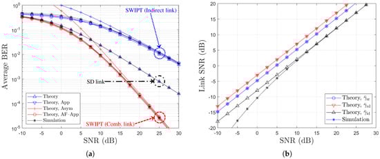
Figure 1.
Performance comparison with respect to SNR (, BPSK, , ): (a) BER vs. SNR (dB) and (b) Link SNR (dB) vs. SNR (dB).
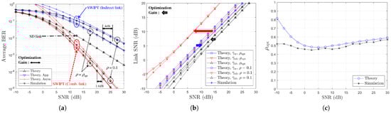
Figure 2.
Performance comparison with respect to SNR (, BPSK, , or ): (a) BER vs. SNR (dB), (b) Link SNR (dB) vs. SNR (dB), and (c) Optimum vs. SNR (dB).
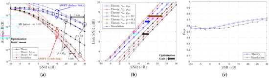
Figure 3.
Performance comparison with respect to SNR (, BPSK, , or ): (a) BER vs. SNR (dB), (b) Link SNR (dB) vs. SNR (dB), and (c) Optimum vs. SNR (dB).
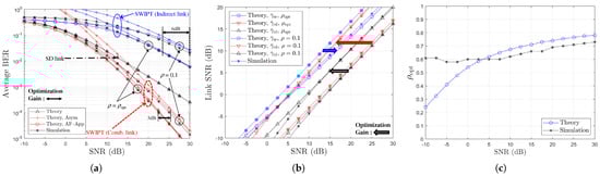
Figure 4.
Performance comparison with respect to SNR (, BPSK, , or ): (a) BER vs. SNR (dB), (b) Link SNR (dB) vs. SNR (dB), and (c) Optimum vs. SNR (dB).
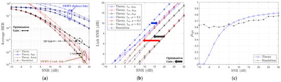
Figure 5.
Performance comparison with respect to SNR (, BPSK, , or ): (a) BER vs. SNR (dB), (b) Link SNR (dB) vs. SNR (dB), and (c) Optimum vs. SNR (dB).
From Figure 1a, it can be observed that the indirect link exhibits inferior performance compared to the direct link, mainly due to the lack of a dedicated power source at the relay. However, when the direct and indirect links are combined, the SWIPT relay system outperforms the direct link alone across the entire SNR range. Furthermore, the numerical results labeled as ‘Theory’, ‘Theory, App’, and ’Theory, AF-App’ show a strong agreement with the simulation results for all SNR values. In particular, ‘Theory, Asym’ accurately reflects the asymptotic BER behavior in the high SNR regime. In Figure 1b, it is shown that the theoretical link SNRs closely match the simulation results, with only minor discrepancies caused by the approximation used in (9), especially in the low SNR region. Additionally, it is confirmed that the SNR of the indirect link, , is limited by the weaker of the SR and RD links, which is consistent with typical behavior in conventional AF relaying systems.
Assuming a path-loss exponent of [18,23], the average channel power gains can be characterized in terms of the relative distances between nodes. Let , , and denote the distances of SD, SR, and RD links, respectively. Under this model, the ratio of the average power gains for the RD and SR links is given by . Moreover, when , it directly follows that . As summarized in Table 1, a change in the ratio from 4 to 1 corresponds to an increase in the RD link distance from one-half to twice the SR link distance. As a result, the modified RD link of (20) becomes increasingly weaker. Following this trend, we aim to investigate how the optimization of the power-splitting factor in the SWIPT relay system impacts the system BER performance. Figure 2, Figure 3, Figure 4 and Figure 5 illustrate the performance variations resulting from the optimization of the power-splitting ratio . For the case of ‘Theory’, the optimal power-splitting (PS) factor was determined by performing an exhaustive search over the interval , based on the analytical BER expression given in (19). In contrast, for the case of ‘Simulation’, we evaluated the numerical BER for all possible PS factors and selected the value that yielded the minimum BER.
Considering the case where , (i.e., prior to optimization), and , Figure 2b indicates that the RD link acts as the weak channel, while the SR link is dominant, leading to . Upon applying the optimized (i.e., in the high SNR region as seen in Figure 2c, the link roles are reversed, and the SNR gap increases, enhancing and reducing the BER. Specifically, Figure 2a shows approximately 4 dB and 1.6 dB SNR gains at and for the indirect and combined links, respectively. Similar trends are observed for . As shown in Figure 3, with , the RD link remains the bottleneck. Optimization leads to at high SNR in Figure 3c, improving and reducing the BER. Corresponding SNR gains are approximately dB and dB at near and , respectively.
For the case of , Figure 4 again highlights the RD link as the limiting factor. Optimization with improves the RD link SNR and results in approximately 6 dB and 3 dB gains at near and , respectively. When , the optimization process leads to a high power-splitting ratio, with , resulting in a significant improvement in the RD link SNR (i.e., bringing it closer to that of the SR link). Nevertheless, improvements are still achieved, with about 2.5 dB gain in combined link performance at , as shown in Figure 5a.
Across all scenarios, Figure 4a and Figure 5a confirm that the analytical expressions and in (24) provide a lower bound on the BER in the low SNR region, and an upper bound that closely approximates the asymptotic BER performance in the high SNR region. It is noteworthy that in the derivation of (19) from (A4), the second term associated with the RD link is obtained by applying an approximation process to the SR link SNR term. Without the optimization for the power-splitting ratio , this approximation introduces inaccuracy in scenarios where the RD link is the dominant weak channel. As a result, discrepancies between the simulation and numerical results for both (19) and (21) are observed in Figure 2a, Figure 3a, Figure 4a and Figure 5a. On the other hand, when is employed as shown in Figure 2, Figure 3, Figure 4 and Figure 5, the SR link becomes the weaker channel. In this case, the asymptotic BER bounds given by (19) and (21) show excellent agreement with the simulation results in the high SNR region. Moreover, although minor mismatches exist, the approximations in (18), obtained via (22), demonstrate good consistency with simulations, affirming the effectiveness of the proposed -optimization strategy. Consequently, from Figure 2, Figure 3, Figure 4 and Figure 5, it is confirmed that optimizing according to (22) effectively enhances the system performance by reinforcing the weaker link, particularly by increasing as the SNR increases and decreases (i.e., as increases).
Note that in the low SNR region, as shown in Figure 2, Figure 3, Figure 4 and Figure 5, significant discrepancies can be observed between the theoretical and simulation results. These discrepancies arise primarily because the theoretical predictions are based on asymptotic BER expressions, which are derived under high SNR assumptions and are thus not accurate in the low SNR regime.
5.2. Multiple SWIPT Relaying Systems
Table 2 shows the channel model used for the multiple SWIPT relaying system and the corresponding link channel power. In Table 2, Ch. Model indicates the environment in which the RD link channel power can be different according to R. Also, Ch. Model provides the SR link channel power-varying environment. Table 3 shows the relationship between the meaning, equation number, and symbols of the legend used in the resulting figures.
Table 2.
Channel models for multiple SWIPT relaying system.
Table 2.
Channel models for multiple SWIPT relaying system.
| Ch. Model | Link | Ch. Power | R |
|---|---|---|---|
| SD | |||
| SR | |||
| RD | 1 | ||
| 2 | |||
| 3 | |||
| 4 | |||
| SD | |||
| SR | 1 | ||
| 2 | |||
| 3 | |||
| 4 | |||
| RD |
Table 3.
Legend description for multiple SWIPT relaying system.
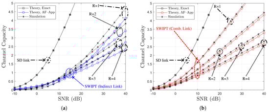
Figure 13.
Channel capacity comparison with respect to SNR (BPSK, , , , Ch. Model ): (a) Indirect link and (b) combined link.
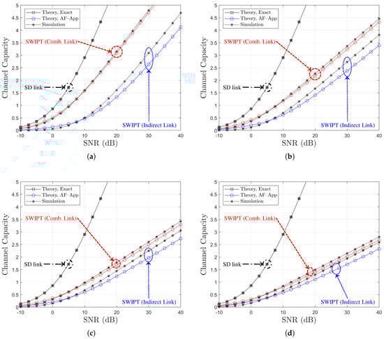
Figure 12.
Channel capacity comparison with respect to SNR (BPSK, , , Ch. Model ): (a) , (b) , (c) , and (d) .
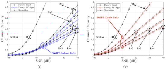
Figure 11.
Channel capacity comparison with respect to SNR (BPSK, , , , Ch. Model ): (a) Indirect link and (b) combined link.
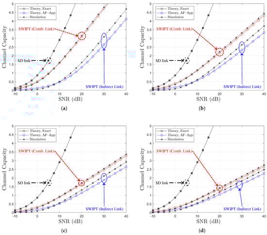
Figure 10.
Channel capacity comparison with respect to SNR (BPSK, , , Ch. Model ): (a) , (b) , (c) , and (d) .
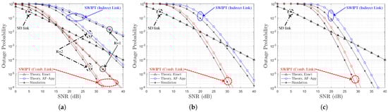
Figure 9.
Outage probability comparison with respect to SNR (BPSK, , , Ch. Model ): (a) , (b) , and (c) .
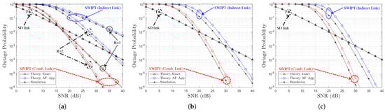
Figure 8.
Outage Probability Comparison with respect to SNR (BPSK, , , Ch. Model ): (a) , (b) , and (c) .
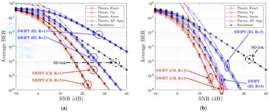
Figure 7.
BER performance comparison with respect to SNR (BPSK, , , Ch. Model ): (a) and (b) .
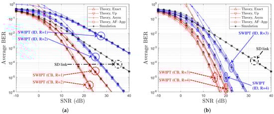
Figure 6.
BER performance comparison with respect to SNR (BPSK, , , Ch. Model ): (a) and (b) .
Table 3.
Legend description for multiple SWIPT relaying system.
| At | Legend | Symbol | Equation | Comment |
|---|---|---|---|---|
| Figure 6 and Figure 7 | Theory, Exact | , , | (32) | Exact MGF |
| Theory, Up | , | (33) | Upper Bounded MGF | |
| Theory, Asym | , | (35) | Asymptotic Bound | |
| Figure 6 and Figure 7 | Theory, AF-App | , | (41) | AF-Approximation |
| , | (42) | |||
| Figure 8 and Figure 9 | Theory, Exact | (45) | Exact only for SD | |
| Theory, AF-App | , | (44) | AF-Approximation | |
| Figure 10, Figure 11, Figure 12 and Figure 13 | Theory, Exact | (46) | Exact only for SD | |
| Theory, AF-App | , | (48) and (49) | AF-Approximation |
5.2.1. BER Comparison
Figure 6 and Figure 7 show the BER performance comparison with respect to the direct link SNR and different parameters of R and for Ch. Model and Ch. Model , respectively. From Figure 6 and Figure 7, it is shown that BER performance can be improved as R increases. Furthermore, it is verified that the numerical results for ‘Theory, Exact’, ‘Theory, Up’ of (33), and ‘Theory, AF-App’ of (41) or (42) well match the simulation results regardless of SNR for both indirect and combined links. Although the larger R increases the discrepancy, we can additionally find that ‘Theory, Asym’ of (35) shows asymptotic BER bounds in good agreement in the high SNR region.
5.2.2. Outage Probability Comparison
In Figure 8 and Figure 9, the outage probability is compared with respect to the direct link SNR for varying values of R, with the power-splitting ratio set to the optimal value, , under Ch. Model and Ch. Model , respectively. From Figure 8 and Figure 9, it can be observed that the outage probability performance improves as R increases. It is verified that the analytical approximation denoted as ‘Theory, AF-App’ provides an upper bound on the outage probability for both the indirect and combined links. Moreover, as R increases, the performance gap between the indirect and the combined links becomes smaller. As R increases, the outage performance difference between indirect and combined links decreases. Furthermore, the analytical result labeled as ‘Theory, Exact’ based on (45) shows an excellent match with the simulation results across all SNR values of the direct link. Although the gap between the simulation results and the ‘Theory, AF-App’ results derived from (44) becomes more pronounced as R increases, the approximate analysis still accurately captures the overall trend of the outage probability performance with increasing R.
5.2.3. Channel Capacity Comparison
Figure 10 and Figure 12 illustrate the channel capacity as a function of the direct link SNR for various values of R, with under Ch. Model and Ch. Model , respectively. In addition, Figure 11 and Figure 13 provide a comparison of channel capacity for , also under the respective channel models, while varying the SNR of the direct link. As observed in Figure 10, Figure 11, Figure 12 and Figure 13, as the channel capacity tends to decrease, R increases. The analytical results labeled as ‘Theory, AF-App’, derived from (48) and (49), serve as lower bounds on the channel capacity, particularly in the certain SNR region. For the indirect link, ‘Theory, AF-App’ shows a mismatch with the simulation results, and this mismatch is inversely proportional to R. On the other hand, ‘Theory, AF-App’ provides a well-aligned lower capacity bound for the combined link. Overall, it is confirmed that the approximately derived analytical results illustrate the channel capacity trend under various SNR and R conditions.
6. Conclusions
In this paper, we have derived the MGF and its approximated bound for SWIPT-enabled AF relaying systems operating without an external power supply at the relay. Based on these MGFs, closed-form BER expressions over quasi-static Rayleigh fading channels were obtained. Additionally, an asymptotic BER expression was derived to provide analytical insight into how the SNR relationship between the SR and RD links impacts the system performance. Using the derived asymptotic BER, we proposed a method to optimize the PS factor , thereby enhancing the performance of the SWIPT relay system. Furthermore, we introduced an analytical approach that interprets the SWIPT relay as a generalized AF relay system, leading to an alternative approximated BER expression. The accuracy of the proposed BER expressions and the optimization framework was validated through simulations. The analytical expressions not only match the simulation results closely but also serve as simplified performance bounds, explicitly revealing the role of the SR and RD link SNRs in determining system performance.
Moreover, the analytical framework was successfully extended to the multiple SWIPT AF relaying system. For the multiple relay scenario, approximated performance metrics including BER, outage probability, and channel capacity were derived and verified. The results demonstrated that increasing the number of relays R improves the BER and outage performance, while the channel capacity tends to decrease with R. The derived asymptotic and approximate expressions provide useful bounds and accurately capture the system behavior across a range of SNRs and network configurations. This extension confirms the generality and robustness of the proposed analytical methods for practical multi-relay SWIPT systems.
Future work may extend this research to alternative SWIPT relaying protocols such as TS, multi-hop relaying, and WPCN configurations. Additionally, the development of energy-aware routing and power allocation algorithms for wireless-powered multi-hop networks remains a promising direction to further improve system efficiency and reliability.
Author Contributions
Conceptualization, K.K. and C.S.; methodology, C.S.; software, K.K.; validation, K.K. and C.S.; formal analysis, K.K.; investigation, K.K. and C.S.; resources, K.K.; data curation, K.K.; writing—original draft preparation, K.K.; writing—review and editing, C.S.; visualization, K.K.; supervision, C.S.; project administration, K.K. and C.S.; funding acquisition, C.S. All authors have read and agreed to the published version of the manuscript.
Funding
This work was supported by the National Research Foundation of Korea (NRF) grant funded by the Korea government (MSIT) (NRF-2021R1A2C2012558).
Data Availability Statement
Data are contained within the article.
Conflicts of Interest
The authors declare no conflicts of interest.
Abbreviations
The following abbreviations are used in this manuscript:
| AF | amplify-and-forward |
| AWGN | additive white Gaussian noise |
| BER | bit error rate |
| BPSK | binary phase shift keying |
| CDF | cumulative distribution function |
| DF | decode-and-forward |
| D2D | device-to-device |
| EH | energy harvesting |
| IP | information processing |
| MGF | moment generating function |
| probability density function | |
| PS | power splitting |
| PSF | power-splitting factor |
| RD | relay-to-destination |
| RF | radio frequency |
| SD | source-to-destination |
| SER | symbol error rate |
| SNR | signal-to-noise ratio |
| SR | source-to-relay |
| SWIPT | simultaneous wireless information and power transfer |
| TS | time splitting |
| WPCN | wireless powered communication network |
Appendix A
For BPSK modulation, the average BER of the SD link can be approximated as the asymptotic form [44] of
where indicates the average SNR of the SD link and is
In order to obtain (A1) from (A2), the approximation is applied, leading to
It should be noted that this asymptotic form is valid for , i.e., under the high SNR approximation [44].
With the same argument, using of (15), in (17) can be asymptotically written and bounded by
It is seen from (A4) that when the SR link SNR is low, i.e., , the BER of SWIPT relay system converges 1, because the second term is nullified. Otherwise when the SR link SNR is strong enough, i.e., , the BER depends on the second term which is written in this regime as
Consequently, the BER expression of the SWIPT relaying systems in (A4) can be asymptotically expressed as of (19).
References
- Zhang, R.; Ho, K. MIMO broadcasting for simultaneous wireless information and power transfer. IEEE Trans. Wirel. Commun. 2013, 5, 1989–2001. [Google Scholar] [CrossRef]
- Song, C.; Park, J.; Clerckx, B.; Lee, I.; Lee, K. Generalized Precoder Designs Based on Weighted MMSE Criterion for Energy Harvesting Constrained MIMO and Multi-User MIMO Channels. IEEE Trans. Wirel. Commun. 2016, 12, 7941–7954. [Google Scholar]
- Song, C.; Jeon, Y. Weighted MMSE Precoder Designs for Sum-Utility Maximization in Multi-User SWIPT Network-MIMO with Per-BS Power Constraints. IEEE Trans. Veh. Technol. 2018, 3, 2809–2813. [Google Scholar] [CrossRef]
- Chen, H.; Zhou, X.; Li, Y.; Wang, P.; Vucetic, B. Harvest-Then-Cooperate: Wireless-Powered Cooperative Communications. IEEE Trans. Signal Process. 2015, 7, 1700–1711. [Google Scholar] [CrossRef]
- Mahama, S.; Asiedu, D.K.P.; Lee, K.-J. Simultaneous wireless information and power transfer for cooperative relay networks with battery. IEEE Access 2017, 5, 13171–13178. [Google Scholar] [CrossRef]
- Asiedu, D.K.P.; Mahama, S.; Jeon, S.-W.; Lee, K.-J. Optimal power splitting for simultaneous wireless information and power transfer in amplify-and-forward multiple-relay systems. IEEE Access 2018, 6, 3459–3468. [Google Scholar] [CrossRef]
- Lee, H.; Lee, K.-J.; Kim, H.; Lee, I. Wireless information and power exchange for energy-constrained device-to-device communications. IEEE Internet Things J. 2018, 5, 3175–3185. [Google Scholar] [CrossRef]
- Asiedu, D.K.P.; Lee, H.; Lee, K.-J. Simultaneous wireless information and power transfer for decode-and-forward Multi-hop Relay systems in energy-constrained IoT networks. IEEE Internet Things J. 2019, 6, 9413–9426. [Google Scholar] [CrossRef]
- He, S.; Xie, K.; Chen, W.; Zhang, D.; Wen, J. Energy-aware routing for SWIPT in multi-hop energy-constrained wireless network. IEEE Access 2018, 6, 17996–18008. [Google Scholar] [CrossRef]
- Zhang, Z.; Pang, H.; Georgiadis, A.; Cecati, C. Wireless power transfer—An overview. IEEE Trans. Indust. Elect. 2018, 66, 1044–1058. [Google Scholar] [CrossRef]
- Krikidis, I. Simultaneous information and energy transfer in large-scale networks with/without relaying. IEEE Trans. Commun. 2014, 62, 900–912. [Google Scholar] [CrossRef]
- Ashraf, N.; Sheihkh, S.A.; Khan, S.A.; Shayea, I.; Jalal, M. Simultaneous Wireless Information and Power Transfer with Cooperative Relaying for Next-Generation Wireless Networks: A Review. IEEE Access 2021, 9, 71482–71504. [Google Scholar] [CrossRef]
- Rossi, P.S.; Ciuonzo, D.; Kansanen, K.; Ekman, T. Performance analysis of energy detection for MIMO decision fusion in wireless sensor networks over arbitrary fading channels. IEEE Trans. Wirel. Commun. 2016, 15, 7794–7806. [Google Scholar] [CrossRef]
- Liu, X.; Wen, Z.; Liu, D.; Zou, J.; Li, S. Joint source and relay beamforming design in wireless multi-hop sensor networks with SWIPT. Sensors 2019, 19, 182. [Google Scholar] [CrossRef] [PubMed]
- Hasna, M.; Alouini, M. End-to-End performance of transmission systems with relays over Rayleigh-fading channels. IEEE Trans. Wirel. Commun. 2003, 6, 1126–1131. [Google Scholar] [CrossRef]
- Anghel, P.; Kaveh, M. Exact symbol error probability of a cooperative network in a Rayleigh-fading environment. IEEE Trans. Wirel. Commun. 2004, 9, 1416–1421. [Google Scholar] [CrossRef]
- Laneman, J.N.; Tse, D.N.C.; Wornell, G.W. Cooperative diversity in wireless networks: Efficient protocols and outage behavior. IEEE Trans. Inf. Theory 2004, 12, 3062–3080. [Google Scholar] [CrossRef]
- Chen, H.; Liu, J.; Zheng, L.; Zhai, C.; Zhou, Y. Approximate SEP analysis for DF cooperative networks with opportunistic relaying. IEEE Signal Process. Lett. 2010, 9, 779–782. [Google Scholar] [CrossRef]
- Amarasuriya, G.; Tellambura, C.; Ardakani, M. Asymptotically-exact performance bounds of AF multi-hop Relaying over Nakagami fading. IEEE Trans. Commun. 2011, 4, 962–967. [Google Scholar] [CrossRef]
- Chaaban, A.; Sezgin, A. Multi-hop relaying: An end-to-end delay analysis. IEEE Trans. Wirel. Commun. 2016, 4, 2552–2561. [Google Scholar] [CrossRef]
- Varshney, N.; Krishna, A.V.; Jagannatham, A.K. Selective DF protocol for MIMO STBC based single/multiple relay cooperative communication end-to-end performance and optimal power allocation. IEEE Trans. Commun. 2015, 7, 2458–2474. [Google Scholar] [CrossRef]
- Varshney, N.; Jagannatham, A.K. MIMO-STBC based multiple relay cooperative communication over time-selective Rayleigh fading links with imperfect channel estimates. IEEE Trans. Veh. Technol. 2017, 7, 6009–6025. [Google Scholar] [CrossRef]
- Lim, S.; Ko, K. Approximation of Multi-hop Relay to Dual-hop Relay and Its Error Performance Analysis. IEEE Commun. Lett. 2017, 2, 342–345. [Google Scholar] [CrossRef]
- Jeong, U.; Ryu, G.; Jang, D.; Ko, K. Exact SEP and Performance Bounds for Orthogonal Space-Time Block Codes in Cooperative Multi-Antenna AF Relaying Networks. Int. J. Commun. Syst. 2019, 9, e3943. [Google Scholar] [CrossRef]
- De Marcellis, A.; Di Patrizio Stanchieri, G.; Faccio, M.; Palange, E.; Constandinou, T.G. A 6 Mbps 7 pJ/bit CMOS Integrated Wireless Simultaneous Lightwave Information and Power Transfer System for Biomedical Implants. Electronics 2024, 13, 1774. [Google Scholar] [CrossRef]
- Al Sabbagh, M.; Amaya, R.E.; Yagoub, M.C.-E.; Almohaimeed, A.M. Overcoming Printed Circuit Board Limitations in an Energy Harvester with Amplitude Shift Keying and Pulse Width Modulation Communication Decoder Using Practical Design Solutions. Electronics 2025, 14, 485. [Google Scholar] [CrossRef]
- Nasir, A.; Zhou, X.; Durrani, S.; Kennedy, R. Relaying Protocols for Wireless Energy Harvesting and Information Processing. IEEE Trans. Wirel. Commun. 2013, 7, 3622–3636. [Google Scholar] [CrossRef]
- Lee, H.; Song, C.; Choi, S.; Lee, I. Outage Probability Analysis and Power Splitter Designs for SWIPT Relaying Systems with Direct Link. IEEE Commun. Lett. 2017, 3, 648–651. [Google Scholar] [CrossRef]
- Ghadi, F.R.; Lopez-Martinez, F.J. Performance Analysis of SWIPT Relay Networks Over Arbitrary Dependent Fading Channels. IEEE Trans. Commun. 2024, 6, 3651–3663. [Google Scholar] [CrossRef]
- Kumar, P.; Dhaka, K. Performance of wireless powered DF relay system under Nakagami-m fading: Relay assists energy-constrained source. IEEE Syst. J. 2020, 2, 2497–2507. [Google Scholar] [CrossRef]
- Babaei, M.; Durak-Ata, L.; Aygolu, U. Performance analysis of dual-hop AF relaying with non-linear/linear energy harvesting. Sensors 2022, 22, 5987. [Google Scholar] [CrossRef] [PubMed]
- Mohjazi, L.; Muhaidat, S.; Dianati, M. Performance analysis of differential modulation in SWIPT cooperative networks. IEEE Signal Process. Lett. 2016, 5, 620–624. [Google Scholar] [CrossRef]
- Lou, Y.; Yu, Q.; Cheng, J.; Zhao, H. Exact BER analysis of selection combining for differential SWIPT relaying systems. IEEE Signal Process. Lett. 2016, 8, 1198–1202. [Google Scholar] [CrossRef]
- Feng, Y.; Leung, V.; Ji, F. Performance study for SWIPT cooperative communication systems in shadowed Nakagami fading channels. IEEE Trans. Wirel. Commun. 2018, 2, 1199–1211. [Google Scholar] [CrossRef]
- Babaei, M.; Aygolu, U.; Basar, E. BER analysis of dual-hop relaying with energy harvesting in Nakagami-m fading channel. IEEE Trans. Wirel. Commun. 2018, 7, 4352–4361. [Google Scholar] [CrossRef]
- Kumar, P.; Dhaka, K. Performance analysis of wireless powered DF relay system under Nakagami-m fading. IEEE Trans. Veh. Technol. 2018, 8, 7073–7085. [Google Scholar] [CrossRef]
- Ghosh, S.; Acharya, T.; Maity, S.P. Outage Analysis in SWIPT Enabled Cooperative AF/DF Relay Assisted Two-Way Spectrum Sharing Communication. IEEE Trans. Cogn. Commun. Netw. 2022, 3, 1434–1443. [Google Scholar] [CrossRef]
- Liu, Z.; Ye, Y.; Lu, G.; Hu, R.Q. System Outage Performance of SWIPT Enabled Full-Duplex Two-Way Relaying with Residual Hardware Impairments and Self-Interference. IEEE Syst. J. 2023, 1, 337–348. [Google Scholar] [CrossRef]
- Kim, K.; Asiedu, D.K.P.; Anokye, P.; Kim, E.; Lee, K.-J. Transmit Power Optimization in Multihop Amplify-and-Forward Relay Systems with Simultaneous Wireless Information and Power Transfer. Electronics 2024, 13, 4232. [Google Scholar] [CrossRef]
- Popoulis, A.; Pillai, S. Probability, Random Variables, and Stochastic Processes, 4th ed.; McGraw Hill: Boston, MA, USA, 2002. [Google Scholar]
- Gradshteyn, I.; Ryzhik, I. Table of Integrals, Series and Products, 7th ed.; Academic Press: San Diego, CA, USA, 2007. [Google Scholar]
- Exponential Integral. Available online: https://en.wikipedia.org/wiki/Exponential_integral (accessed on 19 March 2025).
- Simon, M.; Alouini, M. Digital Communication over Fading Channels; John Wiley & Sons: New York, NY, USA, 2000. [Google Scholar]
- Proakis, J. Digital Communications, 3rd ed.; McGraw Hill: Boston, MA, USA, 1995. [Google Scholar]
Disclaimer/Publisher’s Note: The statements, opinions and data contained in all publications are solely those of the individual author(s) and contributor(s) and not of MDPI and/or the editor(s). MDPI and/or the editor(s) disclaim responsibility for any injury to people or property resulting from any ideas, methods, instructions or products referred to in the content. |
© 2025 by the authors. Licensee MDPI, Basel, Switzerland. This article is an open access article distributed under the terms and conditions of the Creative Commons Attribution (CC BY) license (https://creativecommons.org/licenses/by/4.0/).