Article

A Trident-Fed Wine Glass UWB Antenna Based on Bézier Curve Optimization

Department of Electrical and Information Engineering, Seoul National University of Science and Technology, Nowon-gu, Seoul 01811, Republic of Korea
*
Author to whom correspondence should be addressed.
Electronics 2025, 14(13), 2560; https://doi.org/10.3390/electronics14132560
Submission received: 24 May 2025 / Revised: 21 June 2025 / Accepted: 23 June 2025 / Published: 24 June 2025
(This article belongs to the Section Microwave and Wireless Communications)

Abstract

This work introduces a wine glass-shaped planar ultra-wideband (UWB) antenna. The antenna achieves a compact form factor by reducing lateral width through Bézier curve shaping and a trident feed, while maintaining length for low-frequency operation. The wine-glass-shaped radiator increases shunt capacitance and enhances midband impedance matching, as demonstrated by equivalent circuit analysis, while the trident feed improves matching at higher frequencies. This design yields a 92% fractional bandwidth (3.2–8.7 GHz) within a compact volume of 0.37 λ 0 × 0.13 λ 0 × 0.0013 λ 0 . The prototype is fabricated on two 50-μm-thick polyimide flexible copper-clad laminates (FCCL), and its performance is evaluated in an anechoic chamber. The measured results demonstrate omnidirectional radiation with an efficiency of over 80% across the UWB band. With broad operational range and compactness, the antenna is well-suited for IoT and wearable sensing applications.

1. Introduction

UWB technology has garnered significant attention for applications such as indoor localization, high-speed data transmission, and radio imaging due to its large bandwidth and resilience to interference [1]. Defined by the Federal Communications Commission (FCC) as a system with bandwidth exceeding 500 MHz or at least 20% of the center frequency [2], UWB provides a robust solution for modern wireless communication and sensing applications.
Despite its benefits, the commercialization of UWB antennas remains challenging, especially for compact and conformal applications like mobile devices and wearable electronics. These applications demand planar antennas with broadband impedance matching, efficient radiation performance, and miniaturized designs. Achieving these attributes is especially difficult at lower frequencies, often leading to large volumetric constraints in the design like the textile-based antennas for wireless body area networks (WBAN) [3,4]. Thin-film substrates, such as polyimide-based [5] and liquid crystal polymer-based [6] FCCL, offer a promising alternative due to their enhanced durability, compactness, and conformal properties compared to traditional epoxy-based substrates.
One of the most prevalent planar UWB antenna structures is a bell or elliptical-shaped monopole design [7,8,9,10]. This design introduces a transformation of a fat dipole with a wide arm width, facilitates current path diversion, and harnesses a second resonance mode to achieve wideband. As the substrate gets thinner, however, the impedance-matching bandwidth becomes limited due to a quick increase in the antenna resistance and fluctuation in reactance. To address this issue, several techniques have been proposed, such as defective ground structures [11,12,13], multiple slots and stubs [14,15,16], asymmetric feeding [17,18], etc. These methods add supplement structures to the antenna design, often resulting in an increase in the complexity or degradation of radiation performances.
In this paper, a combination of Bézier-curve-formed, wine-glass shaped (WGS) antenna with a trident feed is introduced, and its design strategy is articulated. Having identified the restriction in impedance matching bandwidth of a conventional bell-shape antenna implemented on a thin substrate, we optimize the shape of the radiator and ground by employing Bézier curve geometry, which enables optimization with minimal control parameters and smoother transitions. The optimized design exhibits a wine-glass shape with concave ground wrapping around the radiator. Analysis with their equivalent circuit models shows induced shunt capacitive component improves impedance matching in the low- and midband frequencies by lowering their Q-factor. Furthermore, the trident feeding technique is employed to enhance higher band matching.
This paper begins with the antenna configuration and key design components, followed by a detailed description of the prototype conventional bell structure with comparative analysis. Next, the study presents simulation and measurement results, highlighting performance metrics against existing designs. Finally, a summary of this research’s key findings and its application, as well as a comparison between this work with other literature.

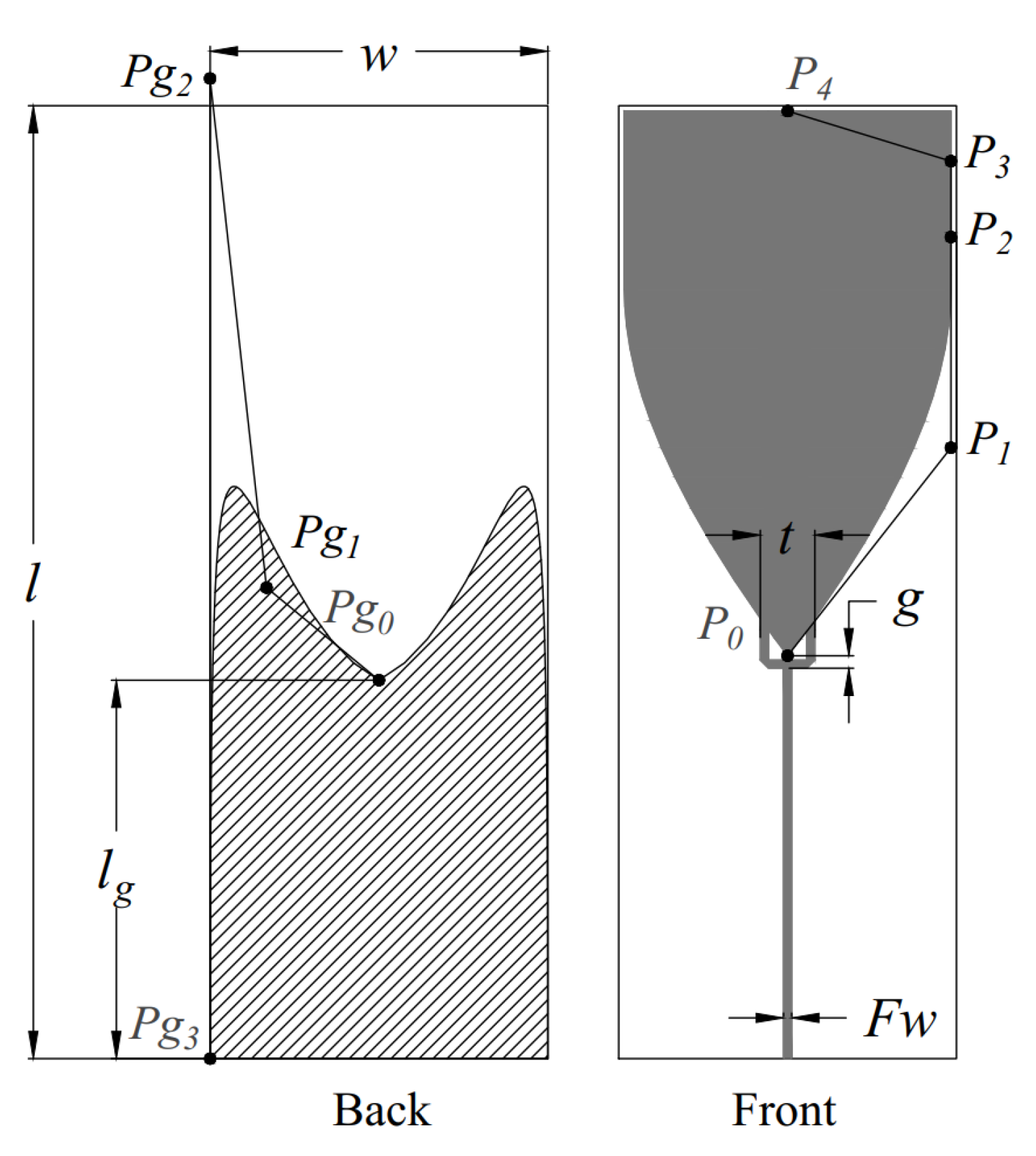
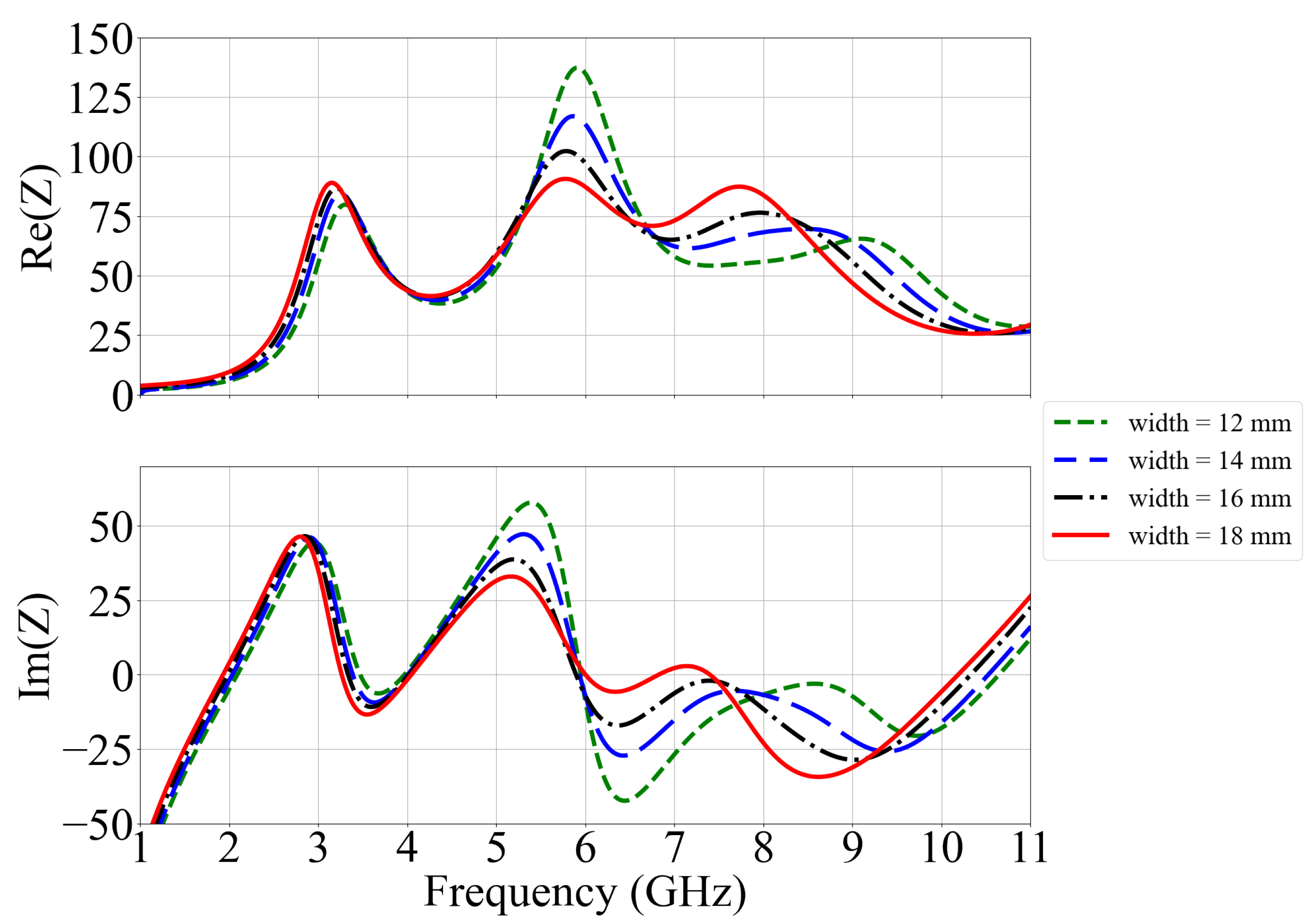
2. Proposed UWB Antenna Configuration

Figure 1 shows the front and rear views of the proposed monopole antenna design with the wine-glass structure synthesized using the Bézier curves. A 50-ohm microstrip feedline is integrated with a trident-shaped impedance transformer to ensure effective impedance matching with the radiator. The concave ground plane enveloping the radiator base introduces enhanced capacitive coupling, compensates for parasitic inductance, and facilitates broadband impedance matching across the 3–6 GHz frequency range. Furthermore, the trident structure is implemented at the feed point, augmenting the excitation of higher-order resonant modes, thereby extending the operational bandwidth. These structures and their matching mechanisms will be discussed in a later section.
The antenna substrate is designed with a thin and flexible polyimide material, which is suitable for conformal integration and compatible with planar fabrication processes. Two Polyamide (PI) layers stacked with a high-dielectric-constant adhesive substance are utilized for the substrate to minimize the antenna’s dimension. As shown in Figure 2, the adhesive layer with Dk = 8 and Df = 0.008 has a thickness of 25 μm, whereas the PI layer with Dk = 3.06 and Df = 0.004 has a thickness of 50 μm. The total thickness of the substrate is about 125 μm, reducing the volume and making the substrate more flexible while maintaining high durability.
Table 1 shows the optimized parameter values for the proposed WGS UWB antenna. The antenna dimensions measured 35 × 12.4 × 0.125 mm 3 or 0.37 λ o × 0.132 λ o × 0.0013 λ o at the lowest resonant frequency (3.2 GHz), where λ o represents the wavelength in free space. Vector points P g 0 , P g 1 , P g 2 , and P g 3 control the ground curve, while P 0 , P 1 , P 2 , P 3 , and P 4 control the radiator curve.

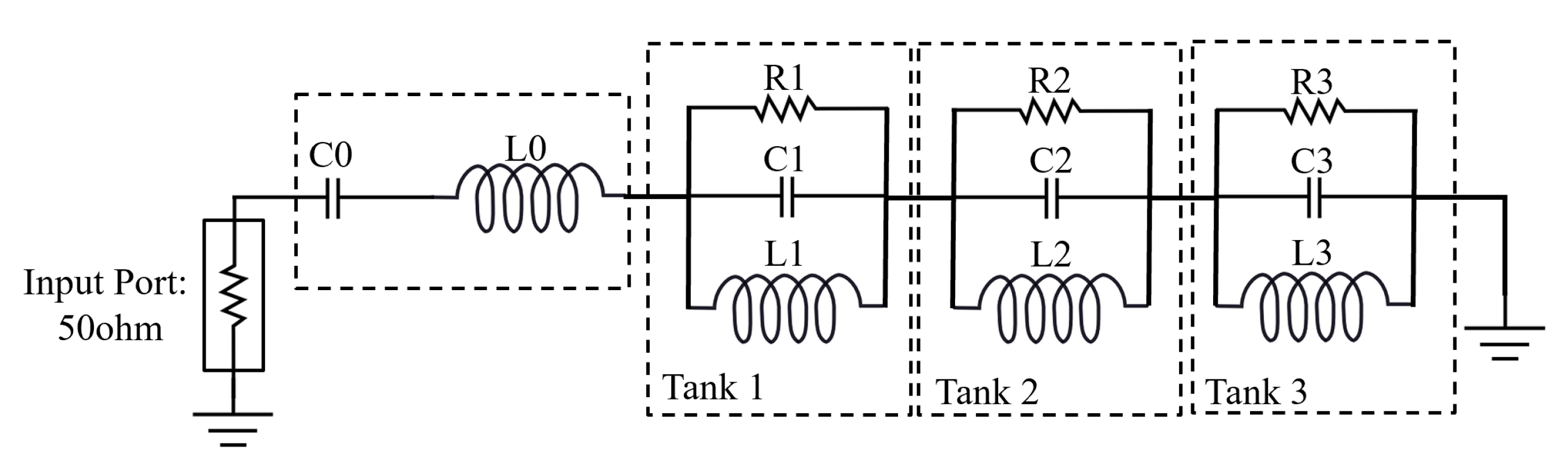
3. Antenna Design Method

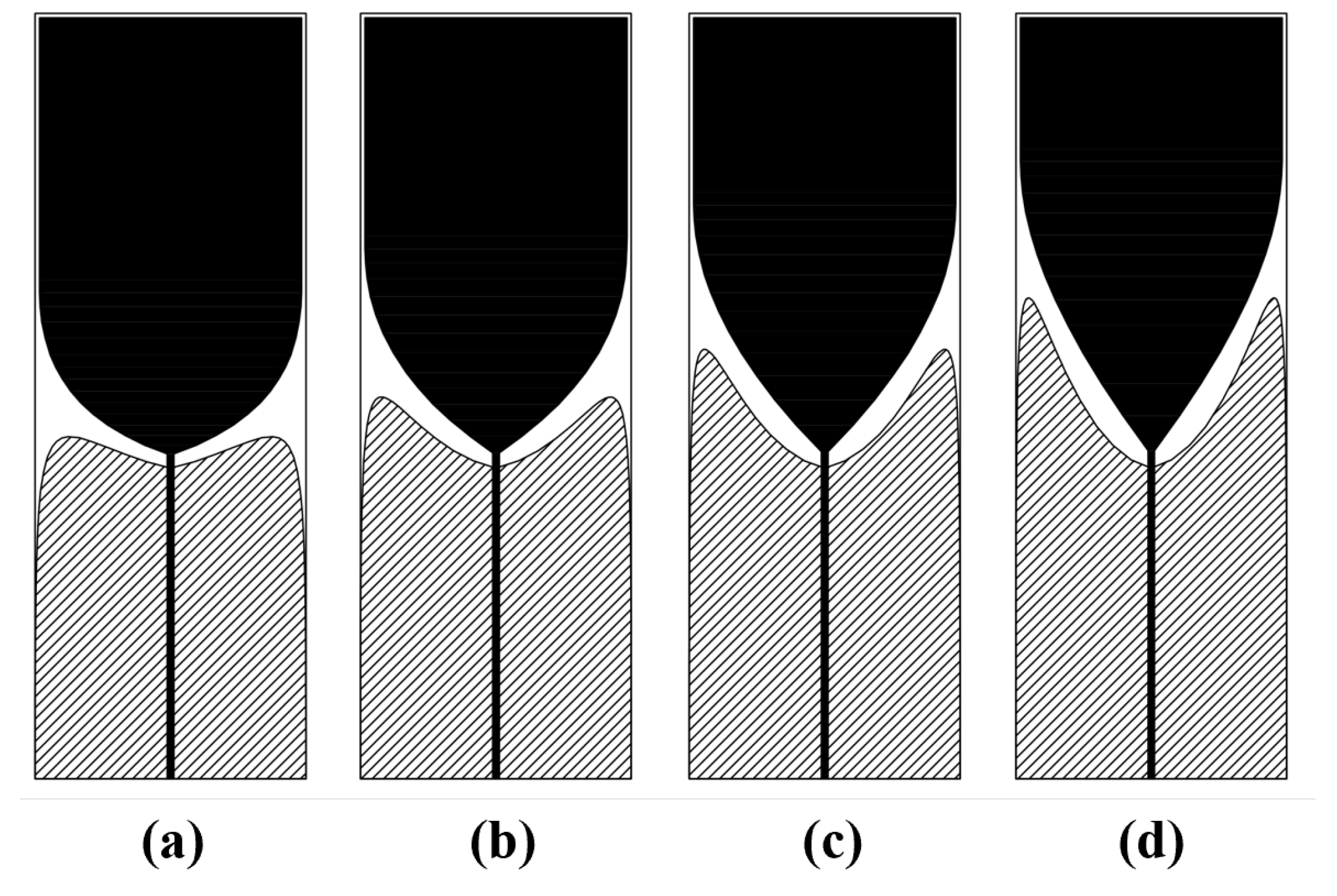
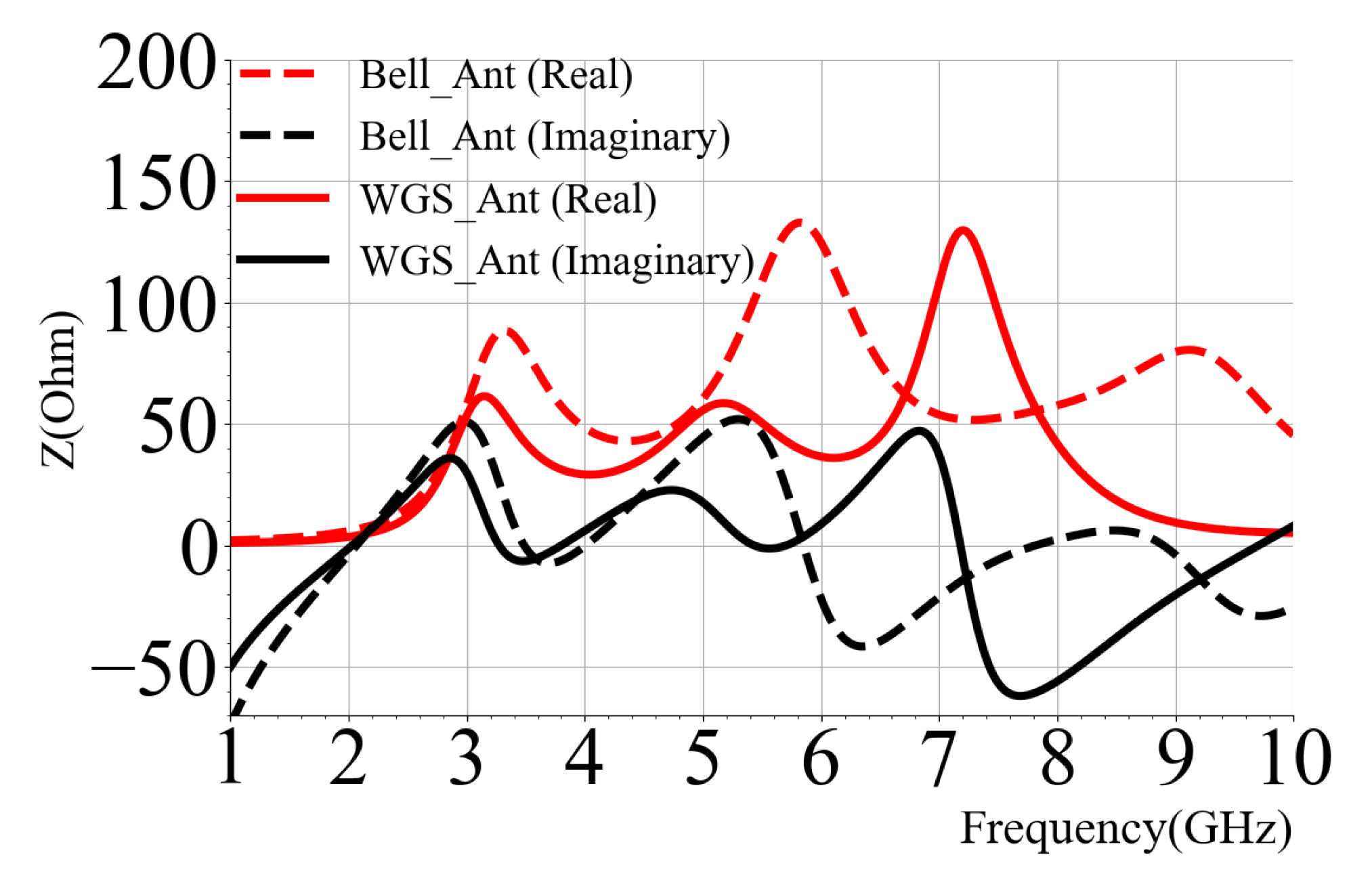
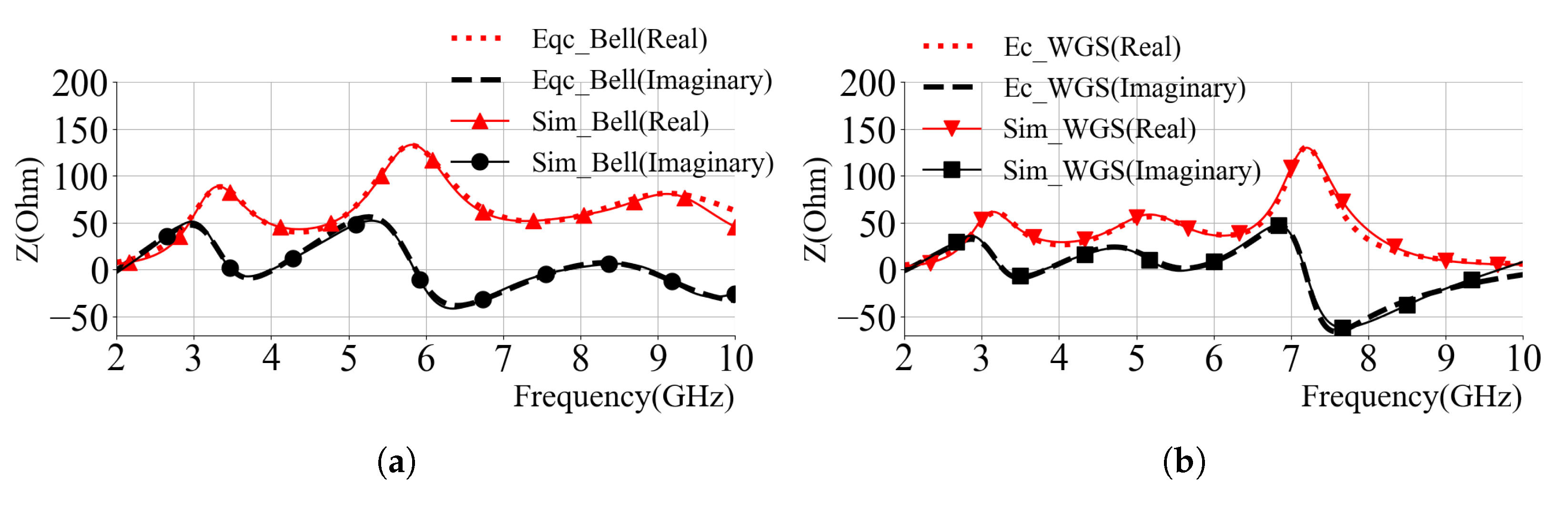
3.1. Prototype Bell Curve Antenna

For broadband applications, sphere antennas and their variations have been used extensively for decades. The antenna length ( l ) is around a quarter wavelength ( λ / 4 ) of the lowest resonant frequency. Curved geometry has been emphasized to generate the needed broadband performance. Moreover, flattening the sphere and reducing the upper half of the circular disc only slightly degrade its performance [19]. An early version of the planer disk design was studied in [20], which shows that the first resonant frequency is mainly associated with the lower half of the circular disk. As a result, we designed a planar monopole antenna with a rectangular top end joined with an elliptical base radiator as a prototype antenna.
Building on prior work [10], the prototype bell-shaped structure is designed with an elliptical radiating and ground surface, as shown in Figure 3. Its radiation mechanism is primarily governed by the surface current propagation along the interface between the radiator and the ground plane. Conceptually analogous to a modified fat dipole, the electromagnetic wave propagates smoothly along the curved conductor surface, radiating energy progressively into free space. The high-frequency component, characterized by shorter wavelength, are confined near the feed, whereas the low- and midband components, with a longer wavelength, are resonant at the larger gap and edges. Additionally, the smooth geometry of the conductor produces input impedance that changes smoothly with frequency [19]. By adjusting the beveled gap, a broadband impedance can be matched.
To explore the limitations of the conventional bell-shaped monopole and identify opportunities for miniaturization, a prototype antenna with dimensions of 35 mm in length and 18 mm in width was first analyzed. The design objective was to minimize the overall antenna size, including both length and width, while maintaining effective UWB performance. However, since the antenna length is closely tied to the quarter-wavelength at the lowest resonant frequency, it is typically retained to ensure proper operation at the low-frequency end. Consequently, width becomes the primary variable for further size reduction.
As shown in Figure 4, reducing the width of the bell-shaped monopole from 18 mm to 12 mm—while keeping the length constant—leads to degraded impedance matching in the midband, with a distinct notch appearing between 4.6 and 6.7 GHz. This behavior is further explained by the Z-parameter analysis in Figure 5, where the second anti-resonant peak exhibits a higher Q-factor for the narrower design, resulting in a sharper impedance transition that complicates midband matching.
To overcome this issue and restore impedance uniformity across the UWB band, the antenna geometry was modified using a wine-glass-shaped radiator designed with Bézier curves, as detailed in the following section. Combined with a trident feed structure, this approach improves midband performance while achieving a more compact lateral footprint.

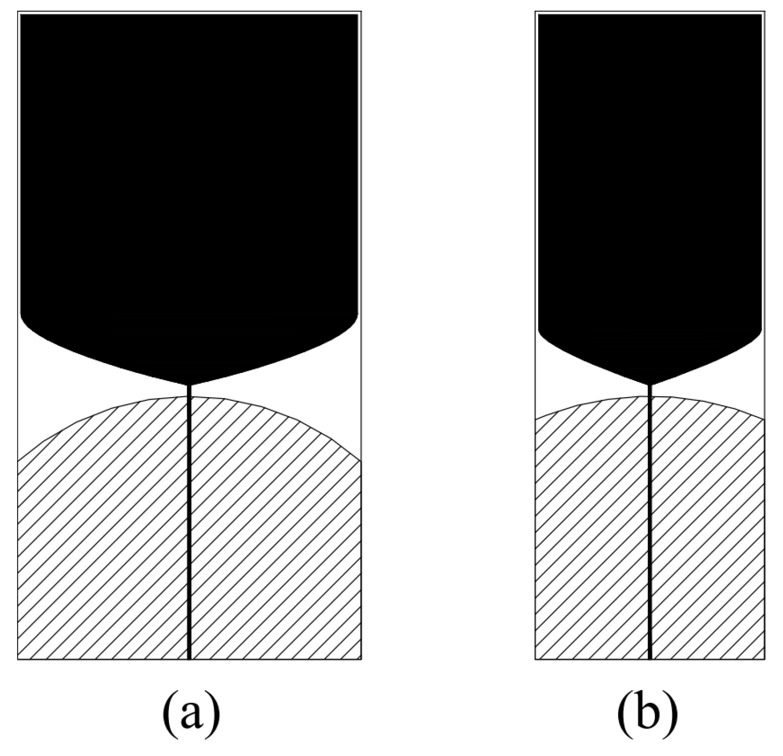
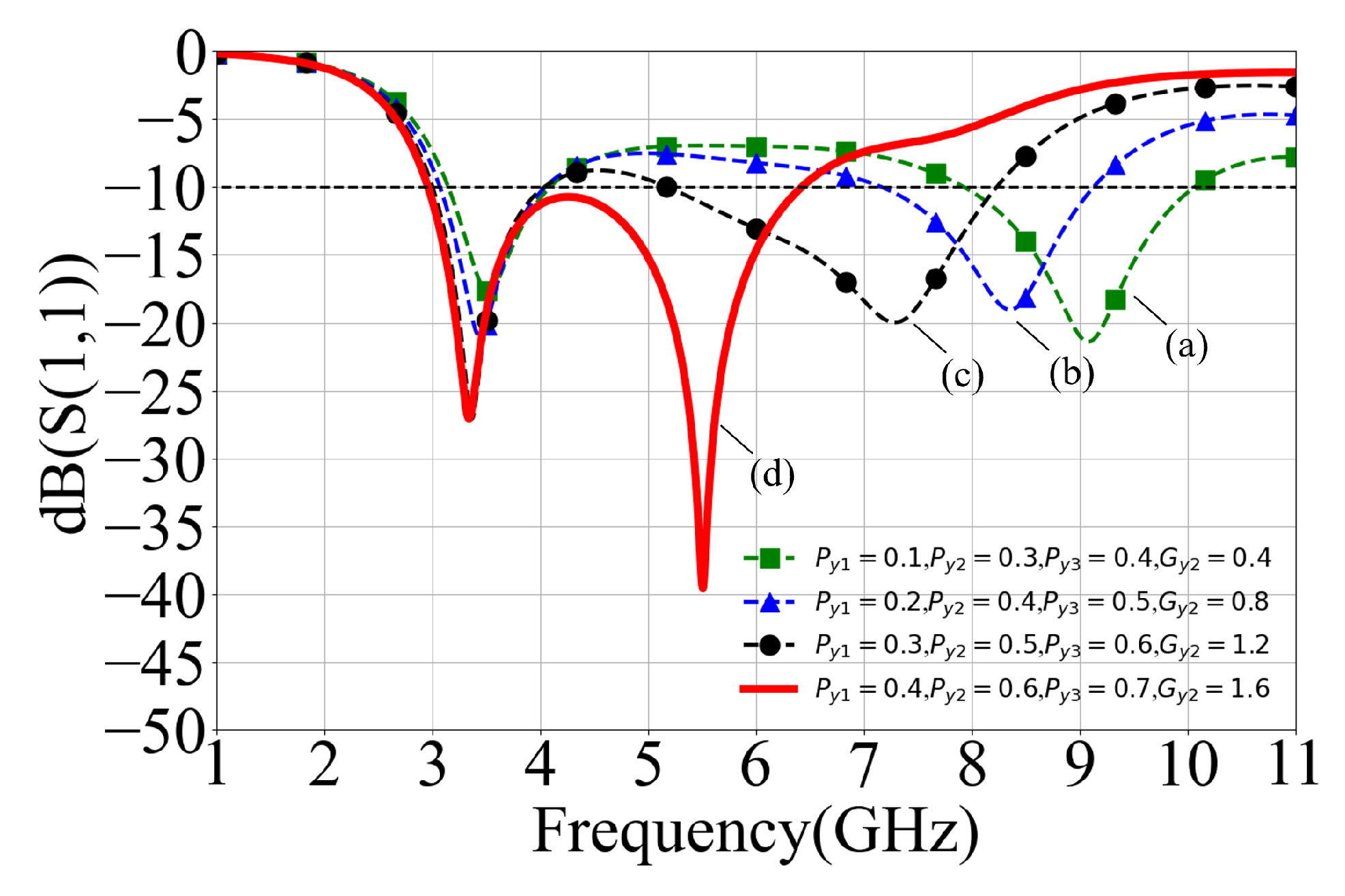
3.2. Bézier Curve Antenna
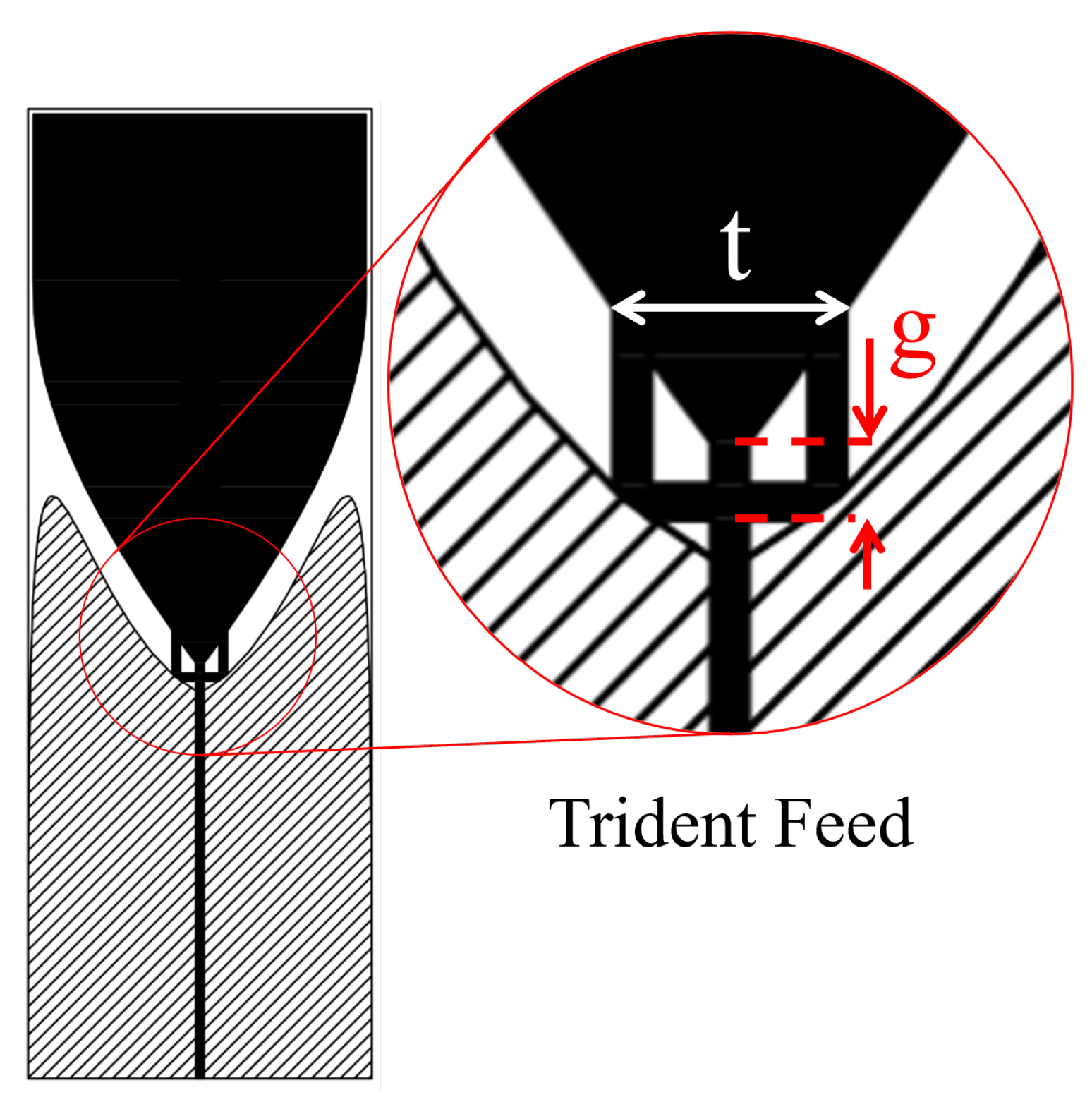
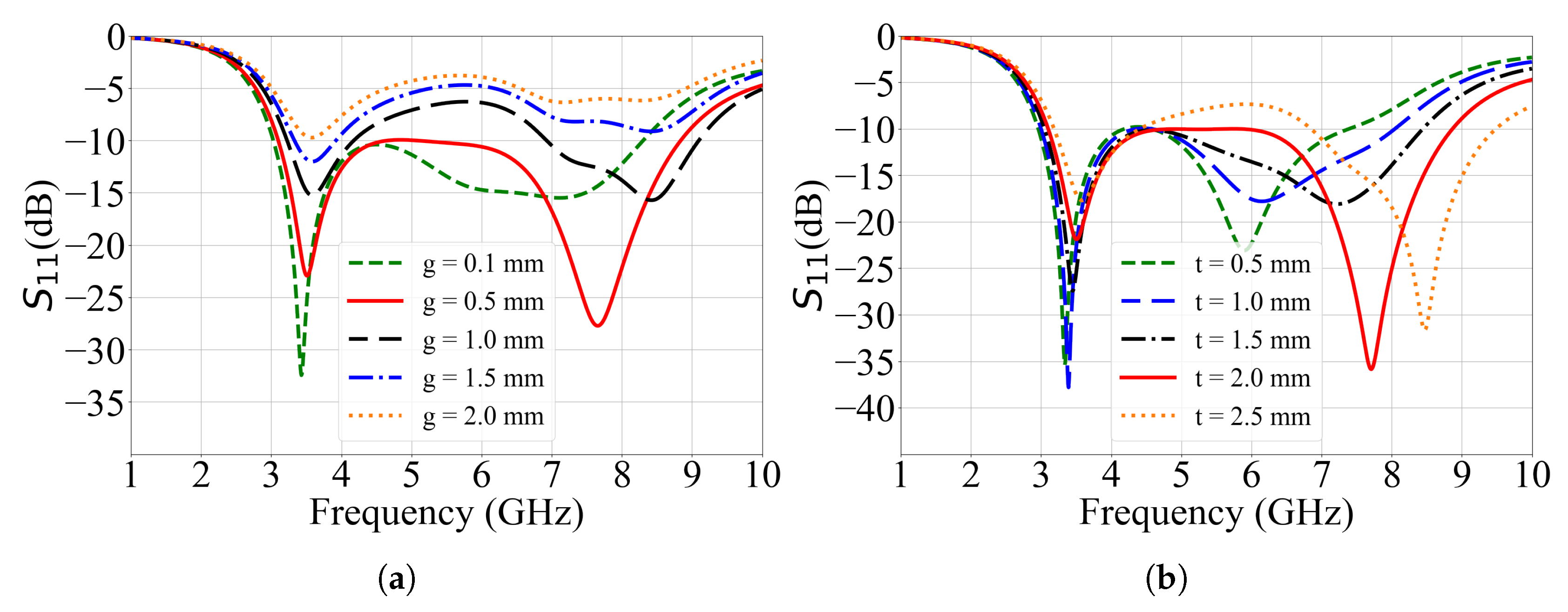
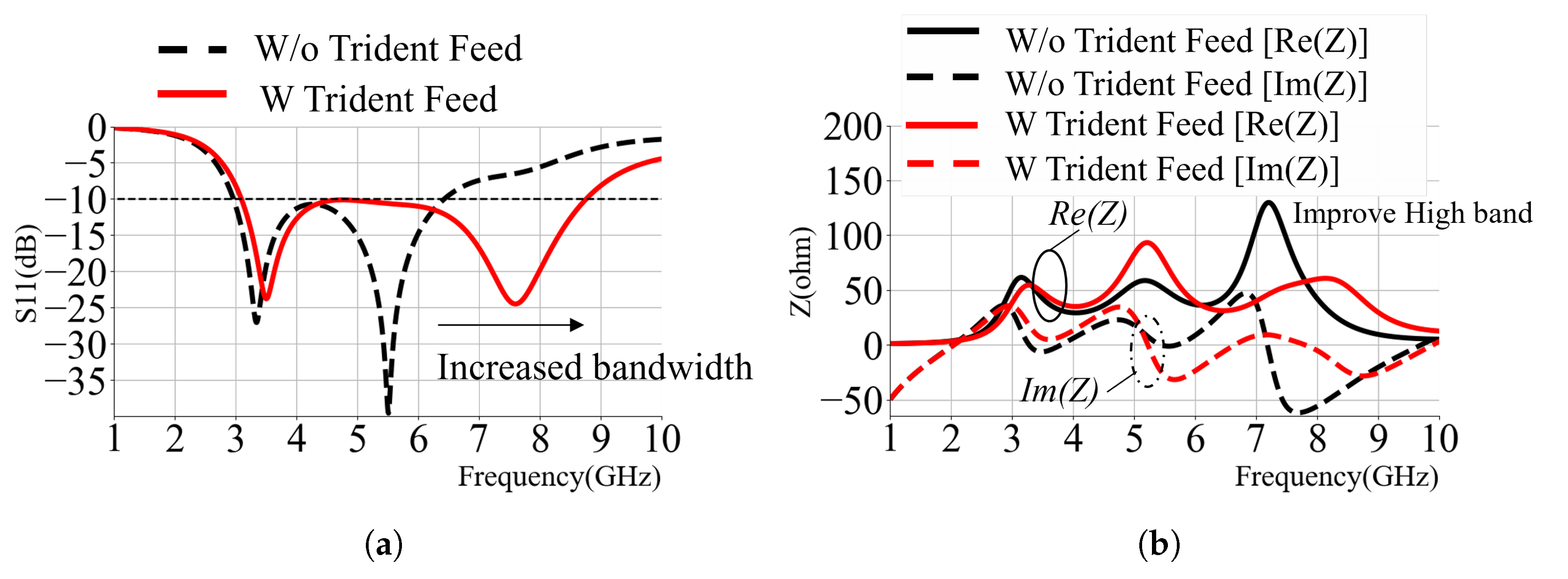
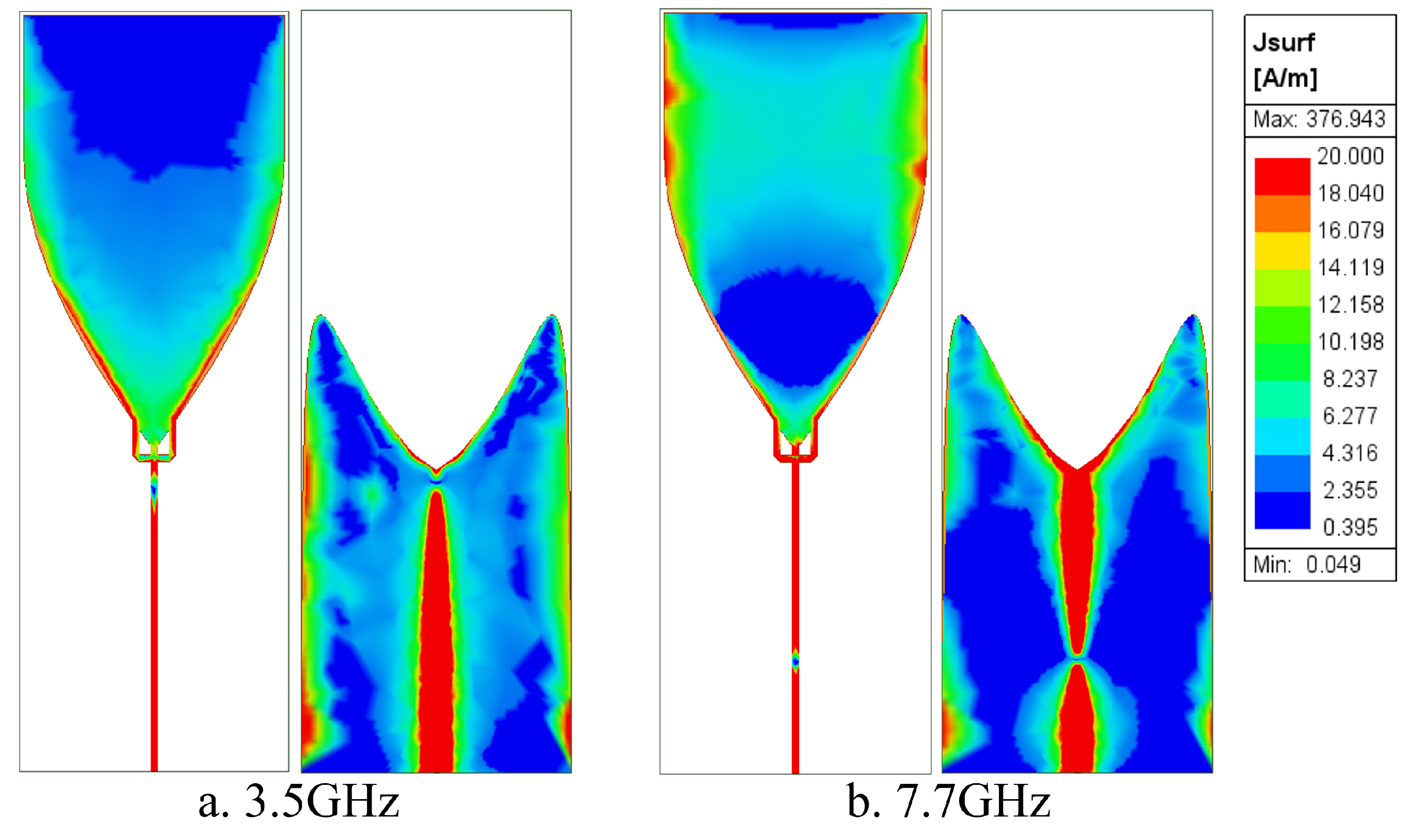
To address the impedance mismatch in the low- and midband frequency, the coupling capacitance was increased by curving the ground plane toward the radiator using Bézier-defined contour. The Bézier curve is used as a straightforward and conventional method for generating a smooth radiator profile with minimal geometric parameters. Utilizing an adaptive multi-objective (AMO) optimization algorithm in the full-wave simulating software (HFSS) and parametric analytic process, the design achieved improved matching in the midband albeit with trade-off in high-frequency performance. The Bézier curve equation is shown as follows:
B ( t ) = i = 0 n n i ( 1 t ) n i t i P i , t [ 0 , 1 ]
B r ( t ) = ( 1 t ) 4 P 4 + 4 t ( 1 t ) 3 P 3 + 6 t 2 ( 1 t ) 2 P 2 + 4 t 3 ( 1 t ) P 1 + t 4 P 0
B g ( t ) = ( 1 t ) 3 P g 3 + 3 t ( 1 t ) 2 P g 2 + 3 t 2 ( 1 t ) P g 1 + t 3 P g 0
where P i denotes the i-th control point and t [ 0 , 1 ] is the curve parameter. Equations (2) and (3) express specific fourth- and third degree Bézier curves, respectively, which are used in the radiator ( B r ) and ground ( B g ) plane, respectively. The radiator profile uses five points ( P 0 P 4 ), as shown in Figure 1, with ( P 0 ) and ( P 4 ) anchored to the origin and the top edge. The upper portion of the radiator also included a rectangular extension similar to the prototype bell design.
For the ground plane (3), four control points ( P g 0 to P g 3 ) are used, where P g 0 and P g 3 ) are fixed at the center area and the bottom corner. The Bézier spline is completed using straight segments and mirrored about the vertical axis to create a symmetric ground configuration. Each position vector P g 0 = ( x i , y i ) is bounded within the width and length, with the origin at ( P 0 ) for the radiator plane and ( P g 0 ) for the ground plane described in the following relationship:
P i = p x i l r , p y i w 2
P g i = g x i l g , g y i w 2
where p x i , p y i , g x i , and g y i [ 0 , 1 ] are normalized control coefficients. The quantities l g and l r represent the total lengths of the radiator and ground geometries, while w denotes the total antenna width. The w / 2 factor ensures symmetry about the central axis.
A parametric study on the spline curve variables, notably the gap between the radiator and ground structure, reveals that the middle anti-resonant can be reduced by introducing more surface coupling between the radiator and ground plane. As illustrated in Figure 6, the curvature converges toward the radiator as we increase the variables ( p y 1 , p y 2 , p y 3 , and g y 2 ). The gap between the radiator and the ground plane remains constant while introducing more surface coupling, forming the distinct wineglass shape (WGS) profile.
Figure 7 presents the S 11 response from the parametric study. As the radiator-ground coupling increases across designs (a) to (d), the second resonant frequency shifts toward lower frequencies. This overlapping between the first and second resonance results in enhanced bandwidth at the low- and midband frequencies. However, this improvement comes at the expense of degraded impedance matching at higher frequencies. Further comparison between the impedance characteristics of the WGS and the bell-shape antenna are shown in Figure 8. The second anti-resonant Q-factor of the WGS antenna was reduced and the third anti-resonant exhibited a sharper Q-factor, shifted to a lower frequency than the bell curve.
The equivalent circuit model is included as a post-design tool to approximate the antenna’s impedance behavior and to conceptually explain the contribution of the wineglass structure to the broadband response. As shown in Figure 9, the equivalent circuit model is derived based on the HFSS-simulated impedance data and derived using the method described in [21]. Over the 0.5 to 10 GHz frequency range, the RLC tank components were extracted to match the corresponding anti-resonant peaks found in the antenna’s simulated impedance graph. Around the DC level, the antenna behaves as an open circuit, modeled by the series capacitor C 0 in the equivalent circuit. The values of the inductor L 0 are designed to match the impedance at the highest frequency of the measurement range. Lastly, the resistance values are chosen to the maximum real part of the impedance at the corresponding anti-resonant.
Table 2 shows the tunned RCL components for the bell and WGS antenna equivalent circuit. In Figure 10, the equivalent circuit model impedance graphs are shown to be closely matched to the full-wave simulation model.
As hypothesized, the WGS antenna structure, compared to the prototype bell shape, doubled the load shunt capacitors ( C 1 , C 2 , C 3 , and C 0 ) while the inductance decreased by half. This leads to lower Q-factors around the low- and midbands while relatively maintaining the resonant frequency. We also observed a significant frequency shift at the higher frequency and increased Q-factors, which can be addressed with modification to the feed region.

3.3. Trident Feed

A trident feed is introduced around the feed region to enhance impedance matching at higher frequencies. This structure offsets the feeding position and introduces multiple current pathways, effectively altering the input impedance of the radiator [22]. The configuration of the trident feed is illustrated in Figure 11. The parameter t represents the distance between the outer branch of the trident, while g defines the vertical gap between the trident junction and the radiator base. A 50-ohm microstrip line with a constant width of f w = 0.3 mm is maintained throughout, and a 45-degree chamfer is applied at the junction between the central and side branches to mitigate sharp discontinuities.
Parametric analysis reveals that increasing either t or g shifts the second resonant toward higher values, as illustrated in Figure 12. The parameter g directly affects the input impedance. When comparing g = 0.1 and 0.5 mm, it is observed that the second resonant shifts upward in the frequency. However, further increasing g beyond this point yields diminishing returns, as the trident effectively overlaps with the ground plane and no longer influences the coupling region.
Similarly, the parameter t influences both impedance matching and resonant frequency. At t = 2 mm, the outer branches of the trident begin intersecting with the ground plane, Further increases degrade matching performance, as shown in Figure 12b. Based on these parametric studies, the optimal configuration for broadband performance is achieved with t = 0.53 mm and g = 2 mm.
The trident feed structure occupied a larger physical area around the feed region, which reduced the coupling capacitance in the input impedance network. To achieve a wider operational bandwidth, a careful balance between the Bézier curve and the trident feed parameters was required. As shown in Figure 13a, the optimized configuration achieves a simulated impedance bandwidth of 3.09 to 8.75 GHz for S 11 < −10 dB, corresponding to a bandwidth of 5.6 GHz or a 2.8:1 ratio. Further insight is provided by the z-parameter plot in Figure 13b, which shows the third anti-resonant peak shifted and compressed, while the second anti-resonate resistance slightly increases. These effects are attributed to the reduced coupling capacitance near the feed region caused by the expanded geometry of the trident structure.
Figure 14 presents the surface current distribution of the WGS antenna with the trident feed at its key resonant frequencies. At 3.5 GHz, the antenna exhibits a classic fundamental dipole mode, characterized by maximum current density at the center and nulls at both ends. The current is predominantly concentrated along the edges of the radiator and ground plane, indicating strong coupling in these regions. At lower frequencies, the length of the ground plane significantly influences the resonance behavior, contributing to the formation of the first resonant mode. In contrast, at higher frequencies, the resonance becomes more localized, with only the top edges of the ground plane actively participating, while the radiator supports a higher-order mode. A portion of the current is also observed to flow along the lower edge of the ground plane, suggesting weak coupling in that region. These observations confirm that the ground plane geometry and its interaction with the radiator are critical in controlling the resonant modes and supporting broadband impedance matching.

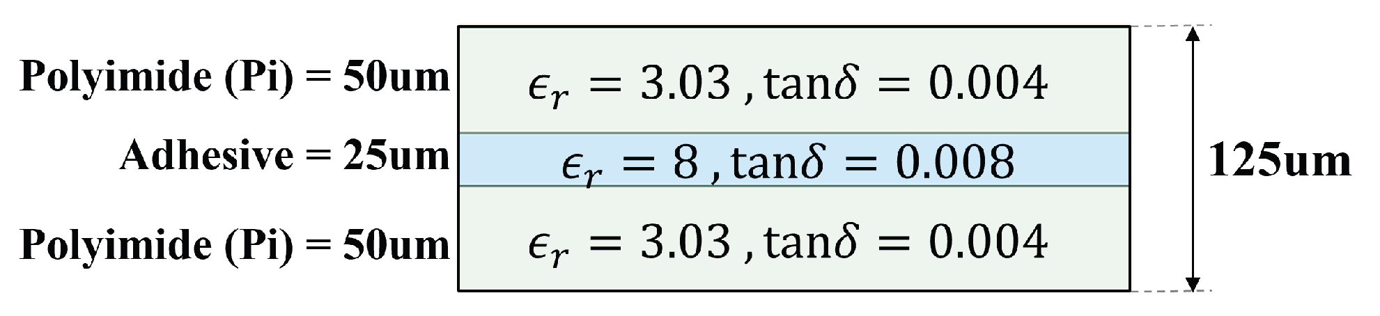
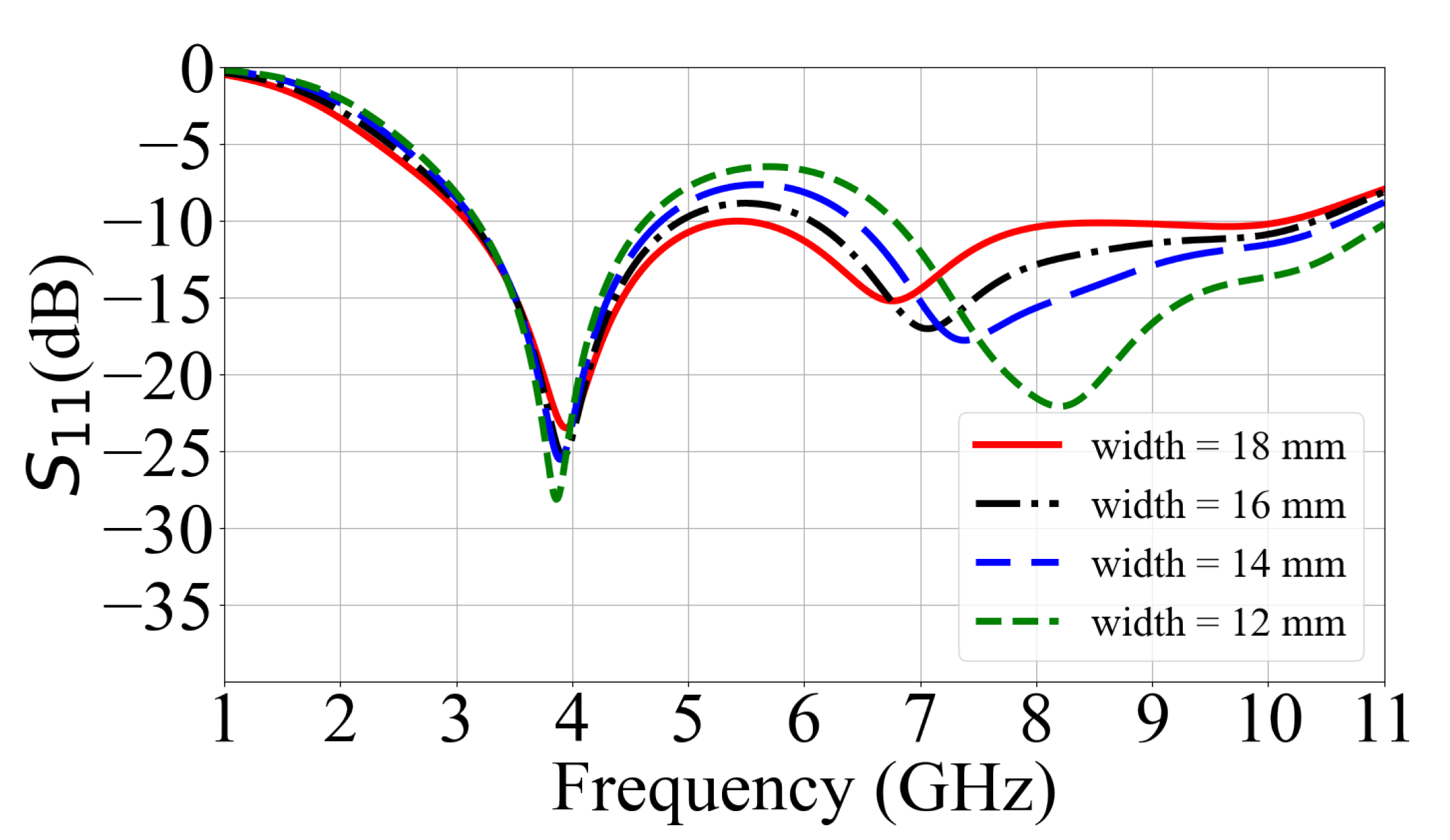
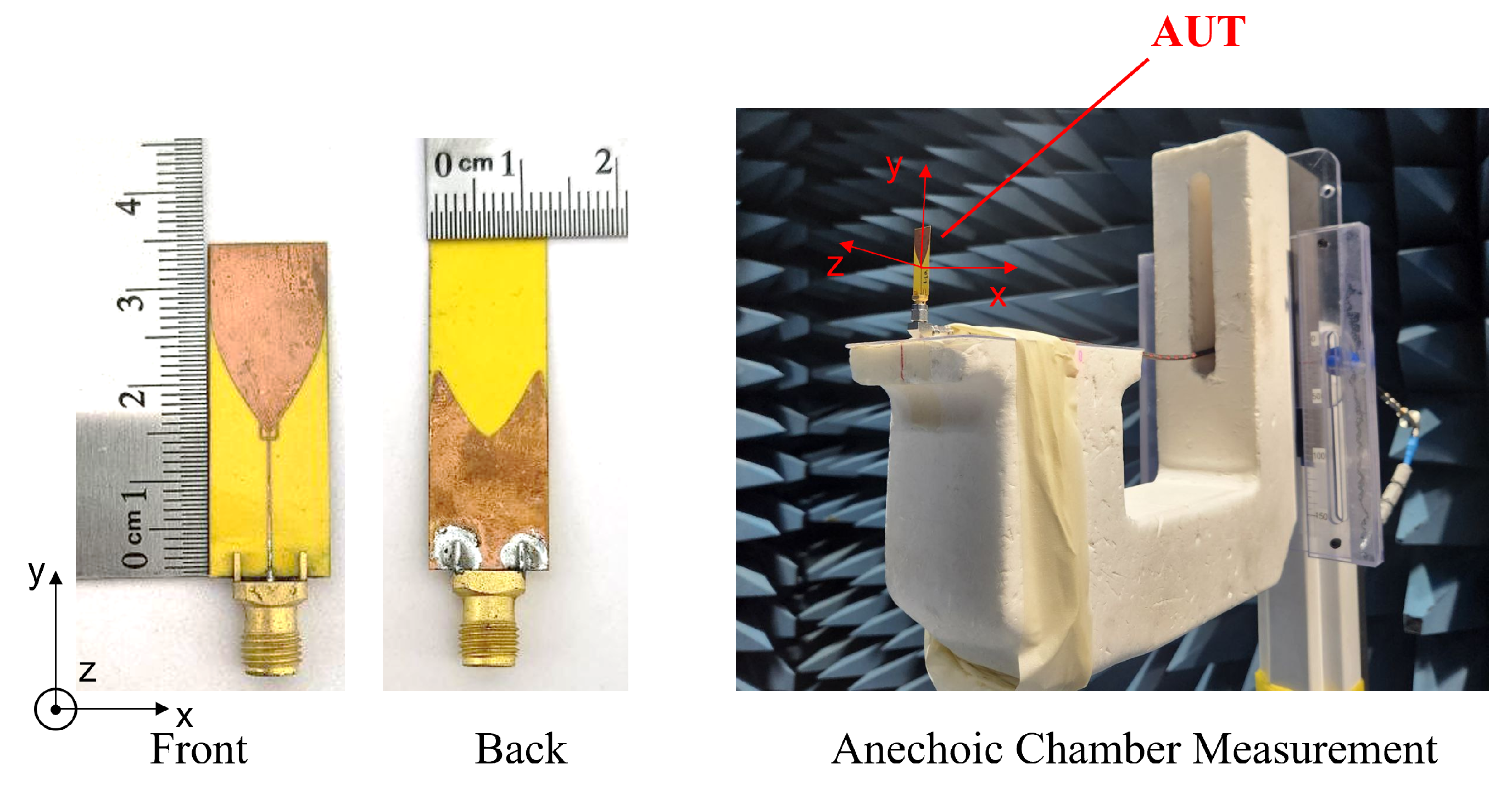
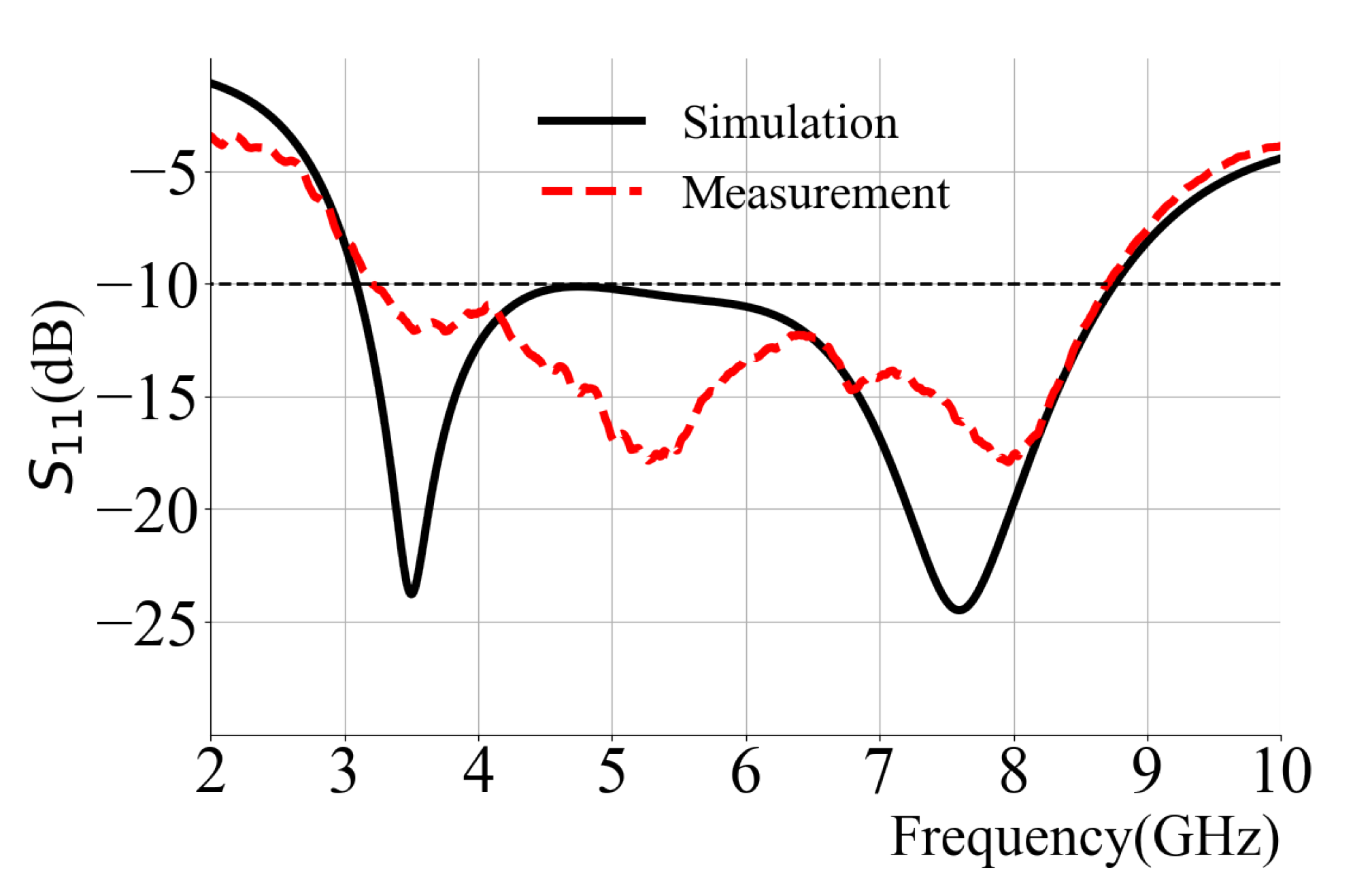
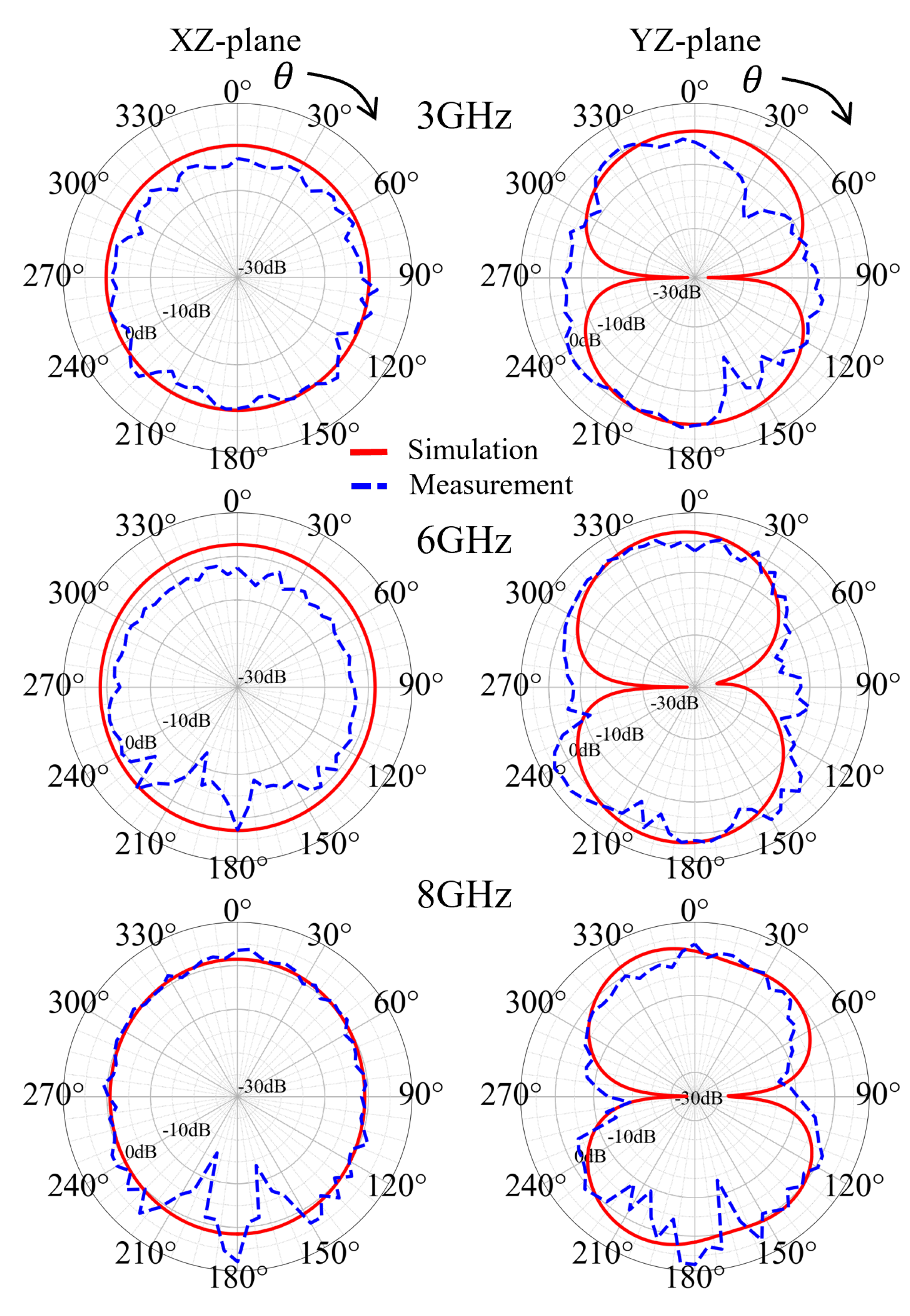
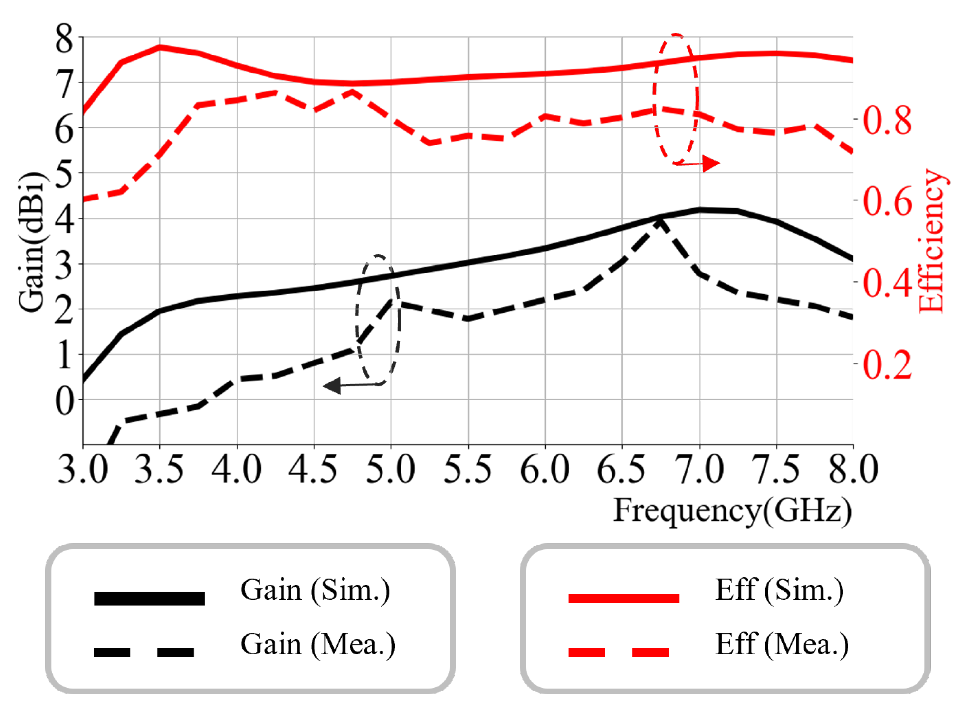
4. Simulation and Measurement

The proposed antenna is fabricated and experimentally tested to validate the design methodology. Figure 15 shows the fabricated prototype, which was measured using a Vector Network Analyzer (VNA) via a 50-ohms SMA connector, along with its setup in the anechoic chamber for radiation measurement. As shown in Figure 16, the measured S 11 results demonstrate a wide impedance bandwidth from 3.2 to 8.7 GHz for S 11 < −10 dB, covering a substantial portion of the UWB spectrum including key channel such as channel 5 and channel 9. These finding confirm the effectiveness of the proposed WGS antenna design in achieving wideband characteristics. Due to errors in the connector and fabrication errors, a discrepancy between the simulation and measurement results is presented but not as significant.
The radiation performance of the proposed antenna was experimentally evaluated in an anechoic chamber, operating within the available measurement frequency range of 3 to 8 GHz. In Figure 17, the antenna exhibits a near omnidirectional radiation pattern in both the XZ-plane ( ϕ = 0°) and YZ-plane ( ϕ = 90°) while sweeping the θ parameter. The angular resolution was set to 5° for both θ and ϕ sweeps. The comparing between simulated (solid) and measured (dashed) results demonstrates good agreement, with both showing the characteristic donut-shaped radiation pattern expected from monopole-like structure.
At higher frequencies (6–7 GHz), the radiation pattern experiences slight downward tilting toward the ground, particularly noticeable in YZ-plane 6 GHz, suggesting a shift in the effective radiation center and minor excitation of the higher-order modes. These variations remain within acceptable limits and do not degrade the unidirectional characteristics significantly. The gain and efficiency of the antenna across frequency are presented in Figure 18. The antenna achieves peak gain of 3.5 dBi around 6–7 GHz, with the gain gradually decreasing to 2.2 dBi at higher frequency. The radiation efficiency remains relatively stable, ranging from 60% at 3 GHz to a peak of 90% around 4–5 GHz, with an average efficiency of approximately 80% across the band. Measured efficiency may exceed simulated values due to the exclusion of connector/feed losses in simulation, chamber calibration tolerances, and fabrication variations. However, the consistency of performance trends confirms the validity of the design.
Table 3 provides a comparative analysis between the proposed antenna and several state-of-the-art UWB antenna designs, in terms of frequency coverage, bandwidth ratio, physical volume, electrical size, and impedance matching techniques. The proposed antenna, with a bandwidth ratio of 2.7:1 (3.2–8.7 GHz), demonstrates competitive performance, while also offering compact volume (54.25 mm 3 ) and a notably thin profile. Although its frequency range is narrower than some broader-band designs, it sufficiently covers key UWB channels commonly used in commercial applications. Combined with its thin profile, this makes it well-suited for integration into mobile and compact devices. The simple structure, featuring a wineglass-shaped radiator and trident feed, facilitates efficient impedance matching, particularly at higher frequencies. In terms of electrical size, the proposed antenna achieves 0.37 λ o × 0.13 λ 0 × 0.0013 λ 0 , where λ 0 is the free-space wavelength at the lowest operating frequency. These compact dimensions, along with shape-optimized geometry and multi-path current distribution strategies, enable wideband performance and validate the antenna’s potential for practical deployment in space-constrained, lightweight, and flexible platforms such as portable UWB communication systems, IoT sensors, and wearable electronics.

5. Conclusions

The proposed antenna introduces a novel design integrating a wineglass structure and a trident feed to achieve compactness, flexibility, and excellent radiation performance across the UWB frequency range. Using a Bézier curve for optimization improves impedance matching in the midband, while the trident feed further extends the operational bandwidth, particularly at higher frequencies. The miniaturization is achieved through the wine-glass radiator profile and trident feed structure, which reduce lateral width while preserving the length needed for low-frequency resonance. This enables the antenna to maintain broadband performance, as confirmed by both simulations and measurements. Although this study focuses on the flat configuration, the effect of substrate bending on antenna performance is acknowledged and will be explored in future work. Its operating over the key channels within the UWB band. Given its compact size and flexible properties, this structure presents an alternative solution for various UWB applications, including mobile communication and sensing, radar imaging, small IoT sensing, and wearable devices. Its unique design and ground structure make it possible to integrate the design into an array structure with a single ground for enhanced gain and direction-sensing capabilities.

Author Contributions

Conceptualization, C.L. and J.-Y.C.; methodology, C.L. and J.-Y.C.; software, C.L.; validation, C.L. and J.-Y.C.; formal analysis, C.L.; investigation, C.L.; resources, J.-Y.C.; data curation, C.L.; writing—original draft preparation, C.L.; writing—review and editing, C.L. and J.-Y.C.; visualization, C.L.; supervision, J.-Y.C.; project administration, J.-Y.C.; funding acquisition, J.-Y.C. All authors have read and agreed to the published version of the manuscript.

Funding

This work was supported in part the Technology Development Program (S3238198) funded by the Ministry of SMEs and Startups.

Data Availability Statement

Data is contained within the article.

Conflicts of Interest

The authors declare no conflicts of interest.

References

  1. Coppens, D.; Shahid, A.; Lemey, S.; Van Herbruggen, B.; Marshall, C.; De Poorter, E. An Overview of UWB Standards and Organizations (IEEE 802.15.4, FiRa, Apple): Interoperability Aspects and Future Research Directions. IEEE Access 2022, 10, 70219–70241. [Google Scholar] [CrossRef]
  2. Federal Communications Commission Revision of Part 15 of the Commission’s Rules Regarding Ultra-Wideband Transmission systems. FCC 02-48, First Report and Order. 2002. Available online: https://docs.fcc.gov/public/attachments/FCC-02-48A1.pdf (accessed on 23 May 2025).
  3. Samal, P.B.; Chen, S.J.; Fumeaux, C. Wearable Textile Multiband Antenna for WBAN Applications. IEEE Trans. Antennas Propag. 2023, 71, 1391–1402. [Google Scholar] [CrossRef]
  4. Jayant, S.; Srivastava, G.; Kumar, S. Quad-Port UWB MIMO Footwear Antenna for Wearable Applications. IEEE Trans. Antennas Propag. 2022, 70, 7905–7913. [Google Scholar] [CrossRef]
  5. Sharma, P.K.; Dzagbletey, P.A.; Chung, J.Y. Evaluation of the thin film polyimide-based holographic metasurface inspired leaky-wave antenna. J. Appl. Polym. Sci. 2024, 141, e55604. [Google Scholar] [CrossRef]
  6. Zhang, Y.; Li, Y.; Hu, M.; Wu, P.; Wang, H. Dual-Band Circular-Polarized Microstrip Antenna for Ultrawideband Positioning in Smartphones with Flexible Liquid Crystal Polymer Process. IEEE Trans. Antennas Propag. 2023, 71, 3155–3163. [Google Scholar] [CrossRef]
  7. Ray, K.P.; Ranga, Y. Ultrawideband Printed Elliptical Monopole Antennas. IEEE Trans. Antennas Propag. 2007, 55, 1189–1192. [Google Scholar] [CrossRef]
  8. John, M.; Ammann, M.J. Antenna Optimization with a Computationally Efficient Multiobjective Evolutionary Algorithm. IEEE Trans. Antennas Propag. 2009, 57, 260–263. [Google Scholar] [CrossRef]
  9. Liu, J.; Zhong, S.; Esselle, K.P. A Printed Elliptical Monopole Antenna with Modified Feeding Structure for Bandwidth Enhancement. IEEE Trans. Antennas Propag. 2011, 59, 667–670. [Google Scholar] [CrossRef]
  10. Dao, D.N.; Chung, J.Y. A Miniaturized Thin-Film UWB Monopole Antenna Implemented with High-Dk Adhesive. Electronics 2023, 12, 3445. [Google Scholar] [CrossRef]
  11. Sim, C.Y.D.; Chang, M.H.; Chen, B.Y. Microstrip-Fed Ring Slot Antenna Design with Wideband Harmonic Suppression. IEEE Trans. Antennas Propag. 2014, 62, 4828–4832. [Google Scholar] [CrossRef]
  12. Yang, W.; Xun, M.; Che, W.; Feng, W.; Zhang, Y.; Xue, Q. Novel Compact High-Gain Differential-Fed Dual-Polarized Filtering Patch Antenna. IEEE Trans. Antennas Propag. 2019, 67, 7261–7271. [Google Scholar] [CrossRef]
  13. Din, I.U.; Ullah, W.; Abbasi, N.A.; Ullah, S.; Shihzad, W.; Khan, B.; Jayakody, D.N.K. A Novel Compact Ultra-Wideband Frequency-Selective Surface-Based Antenna for Gain Enhancement Applications. J. Electromagn. Eng. Sci. 2023, 23, 188–201. [Google Scholar] [CrossRef]
  14. Gopikrishna, M.; Krishna, D.D.; Anandan, C.K.; Mohanan, P.; Vasudevan, K. Design of a Compact Semi-Elliptic Monopole Slot Antenna for UWB Systems. IEEE Trans. Antennas Propag. 2009, 57, 1834–1837. [Google Scholar] [CrossRef]
  15. Narbudowicz, A.; John, M.; Sipal, V.; Bao, X.; Ammann, M.J. Design Method for Wideband Circularly Polarized Slot Antennas. IEEE Trans. Antennas Propag. 2015, 63, 4271–4279. [Google Scholar] [CrossRef]
  16. Awan, D.; Bashir, S.; Bari, I.; Bashir, M.A.; Ali, H.; Ibrahim, I.M.; Kiani, S.H.; Savci, H.S.; Zahriladha, Z. A Circular Shape Arc Slot Ultra-Wideband Antenna for Biomedical Applications. J. Electromagn. Eng. Sci. 2024, 24, 418–425. [Google Scholar] [CrossRef]
  17. Zebiri, C.E.; Lashab, M.; Sayad, D.; Elfergani, I.T.E.; Sayidmarie, K.H.; Benabdelaziz, F.; Abd-Alhameed, R.A.; Rodriguez, J.; Noras, J.M. Offset Aperture-Coupled Double-Cylinder Dielectric Resonator Antenna with Extended Wideband. IEEE Trans. Antennas Propag. 2017, 65, 5617–5622. [Google Scholar] [CrossRef]
  18. Mei, S.; Ping, Z.Y. A Chip Antenna in LTCC for UWB Radios. IEEE Trans. Antennas Propag. 2008, 56, 1177–1180. [Google Scholar] [CrossRef]
  19. Stutzman, W.L.; Thiele, G.A. Antenna Theory and Design; Wiley: Hoboken, NJ, USA, 2013. [Google Scholar]
  20. Liang, J.; Chiau, C.; Chen, X.; Parini, C. Study of a printed circular disc monopole antenna for UWB systems. IEEE Trans. Antennas Propag. 2005, 53, 3500–3504. [Google Scholar] [CrossRef]
  21. Wang, S.; Niknejad, A.; Brodersen, R. Circuit modeling methodology for UWB omnidirectional small antennas. IEEE J. Sel. Areas Commun. 2006, 24, 871–877. [Google Scholar] [CrossRef]
  22. Dzagbletey, P.A.; Jeong, J.Y.; Chung, J.Y. Ultra-Wideband Trident Inset-Fed Monopole Antenna with a 3-D Conical Ground. IEEE Access 2021, 9, 2592–2601. [Google Scholar] [CrossRef]
  23. Chahat, N.; Zhadobov, M.; Sauleau, R.; Ito, K. A Compact UWB Antenna for On-Body Applications. IEEE Trans. Antennas Propag. 2011, 59, 1123–1131. [Google Scholar] [CrossRef]
  24. Kirtania, S.G.; Younes, B.A.; Hossain, A.R.; Karacolak, T.; Sekhar, P.K. CPW-Fed Flexible Ultra-Wideband Antenna for IoT Applications. Micromachines 2021, 12, 453. [Google Scholar] [CrossRef]
Figure 1. Proposed WGS antenna front and back copper.
Electronics 14 02560 g001
Figure 2. The thin-film substrate layout, properties, and dimension.
Electronics 14 02560 g002
Figure 3. The prototype bell-shape antenna with widths of (a) 18 mm and (b) 12 mm. (Hatched: Back copper, Black-shade: Front copper).
Electronics 14 02560 g003
Figure 4. The S-parameter for bell-shape antenna comparing different widths.
Electronics 14 02560 g004
Figure 5. The Z-parameter for bell-shape antenna comparing different widths.
Electronics 14 02560 g005
Figure 6. Antennas with incrementally increasing Bézier curve: (a) p y 1 = 0.1 , p y 2 = 0.3 , p y 3 = 0.4 , g y 2 = 0.4 ; (b) p y 1 = 0.2 , p y 2 = 0.4 , p y 3 = 0.5 , g y 2 = 0.8 ; (c) p y 1 = 0.3 , p y 2 = 0.5 , p y 3 = 0.6 , g y 2 = 1.2 ; (d) p y 1 = 0.4 , p y 2 = 0.6 , p y 3 = 0.7 , g y 2 = 1.6 . (Hatch: Back copper, Black-shade: Front copper).
Electronics 14 02560 g006
Figure 7. The S 11 graph of the WGS structure as the Bézier curve points incrementally increase the second resonant shifted to the lower frequency.
Electronics 14 02560 g007
Figure 8. The comparison of the impedance graph between the bell-shape and WGS antenna shows a reduction in the Q-factor in the midband.
Electronics 14 02560 g008
Figure 9. The derived equivalent circuit models based on the impedance graph of the antenna HFSS simulation result.
Electronics 14 02560 g009
Figure 10. The impedance from the simulation and equivalent circuit model of the (a) bell curve and (b) spline curve.
Electronics 14 02560 g010
Figure 11. The trident feed parameters on the proposed antenna. (Hatched: Back copper, Black-shade: Front copper).
Electronics 14 02560 g011
Figure 12. The s-parameter comparison with different trident parameters: (a) g mm (b) t mm.
Electronics 14 02560 g012
Figure 13. The proposed antenna with and without trident feed: (a) S 11 graph and (b) impedance graph.
Electronics 14 02560 g013
Figure 14. The derived equivalent circuit models based on the impedance graph of the antenna HFSS simulation result.
Electronics 14 02560 g014
Figure 15. The photograph of the fabricated Tulip-shaped antenna with trident feed, and the mounting position at the anechoic chamber.
Electronics 14 02560 g015
Figure 16. The S 11 graph of the simulation and measurement of the proposed antenna. (The horizontal dashed line at 10 dB indicates the typical threshold for acceptable impedance matching).
Electronics 14 02560 g016
Figure 17. The simulated and measured radiation pattern.
Electronics 14 02560 g017
Figure 18. Shows the peak gain and efficiency of the proposed antenna.
Electronics 14 02560 g018
Table 1. Dimensions of proposed antenna (Unit: mm).
wl l g Fwtg
12.435.013.80.32.00.68
P g 0 P g 1 P g 2 P g 3
(0,0)(0,1)(0,3)(0,1)
P 0 P 1 P 2 P 3 P 4
(0,1)(0,1.4)(1,1.4)(1,1.5)(1,1)
Table 2. Component values of the equivalent circuit.
Values (pF)Values (nH)Values ( Ω )Q-Factor
Bell Antenna
1.70 ( C 0 )0.63 ( L 0 )
1.90 ( C 1 )1.20 ( L 1 )82.00 ( R 1 )3.26 ( Q 1 )
0.95 ( C 2 )0.79 ( L 2 )119.61 ( R 2 )4.14 ( Q 2 )
0.75 ( C 3 )0.40 ( L 3 )72.48 ( R 3 )3.14 ( Q 3 )
WGS Antenna
2.40 ( C 0 )0.57 ( L 0 )
3.49 ( C 1 )0.72 ( L 1 )56.36 ( R 1 )3.92 ( Q 1 )
2.00 ( C 2 )0.47 ( L 2 )50.00 ( R 2 )3.26 ( Q 2 )
1.68 ( C 3 )0.29 ( L 3 )120.81 ( R 3 )9.19 ( Q 3 )
Table 3. Comparison of antenna performance.
Ref.Freq. RangeBand-WidthVolumeElectrical SizeMatching Technique
(GHz) Ratio ( mm 3 ) ( λ 0 × λ 0 × λ 0 ) *
[7]1–121:12 12,960 0.31 × 0.30 × 0.0053 Elliptical & Trident Feed
[8]3–111:3.61920 0.40 × 0.30 × 0.016 Optimized Bézier curve Bell Ant
[10]6–91:1.536 0.25 × 0.16 × 0.008 Elliptical Thin-film Ant
[15]3.2–6.11:1.92640 0.85 × 0.70 × 0.0053 Circular Slot Ant
[23]3–11.21:3.7400 0.25 × 0.10 × 0.016 Slot Monopole Ant
[24]3.04–10.71:3.5 164.5 0.48 × 0.25 × 0.0014 CPW-Fed Circular Monopole
This paper3.2–8.71:2.7 54.25 0.37 × 0.13 × 0.0013 Wineglass Shape & Trident Feed
* λ 0 : wavelength in free-space, measured at lowest frequency of the antenna.
Disclaimer/Publisher’s Note: The statements, opinions and data contained in all publications are solely those of the individual author(s) and contributor(s) and not of MDPI and/or the editor(s). MDPI and/or the editor(s) disclaim responsibility for any injury to people or property resulting from any ideas, methods, instructions or products referred to in the content.

