Article

Fault-Tolerant Operation of Photovoltaic Systems Using Quasi-Z-Source Boost Converters: A Hardware-in-the-Loop Validation with Typhoon HIL

by
Basit Ali
1,*,
Mothana S. A. Al Sunjury
2,
Adnan Ashraf
1,
Mohammad Meraj
1 and
Pietro Tricoli
1
1
Department of Electronic, Electrical and Systems Engineering, University of Birmingham, Edgbaston Campus, Birmingham B15 2TT, UK
2
Technical Engineering College of Mosul, Northern Technical University, Mosul 41002, Iraq
*
Author to whom correspondence should be addressed.
Electronics 2025, 14(13), 2522; https://doi.org/10.3390/electronics14132522 (registering DOI)
Submission received: 1 May 2025 / Revised: 18 June 2025 / Accepted: 19 June 2025 / Published: 21 June 2025
(This article belongs to the Special Issue Compatibility, Power Electronics and Power Engineering)

Abstract

:
Photovoltaic (PV) systems are prone to different types of faults, primarily electrical faults such as line-to-ground (L-G) and line-to-line (L-L) faults, which can significantly reduce system performance, efficiency, and lead to increased power losses. Moreover, mechanical damage caused by environmental stressors (such as wind, hail, or temperature variations), aging, or improper installation also contribute to system degradation. This study specifically focuses on electrical faults and proposes a method that not only enables the isolation of faulty modules but also ensures the uninterrupted operation of the remaining healthy modules and also assists in the localization of faults. Unlike benchmarked techniques-based boost converters, the Quasi-Z-Source Boost Converter (QZBC) topology offers improved voltage boosting with high gain values, reduced component stress, and enhanced reliability when the PV system is undergoing fault identification and localization algorithms. A 600-watt PV system connected with a Quasi-Z-Source Boost Converter was implemented and tested under different fault conditions using a hardware-in-the-loop (HIL) setup with Typhoon HIL. All the component values of the QZBC were calculated based on the system requirements rather than assumed, ensuring both practical feasibility and design accuracy. The experimental results show that the converter achieved an efficiency of over 96% under electrical-fault conditions, confirming the effectiveness of the quasi-Z-source boost converter in maintaining a stable power output when the PV system is undergoing fault identification and localization algorithms. The study further highlights the benefits of HIL-based testing for evaluating PV-system resilience and fault-handling capabilities in real-time conditions using a Typhoon HIL 404 environment.

1. Introduction

Electricity consumption has been shifted towards renewable-energy sources, which has shown a significant increase in the deployment of grid-connected photovoltaic systems. Among renewable-energy sources, photovoltaic (PV) systems have seen remarkable growth and a significant penetration in many applications such as solar-battery charging stations, space systems, telecommunication, residences, electric vehicles, and commercial installations, as well as parts of hybrid power systems [1,2].
However, the increased deployment of PV systems, especially in distributed and mobile environments such as EVs, introduces new challenges related to fault detection and system protection. These include an increased risk of line-to-ground and line-to-line faults due to variable environmental conditions, bidirectional power flow, and complex load behaviors.
Therefore, understanding and mitigating these faults is critical for the safe and efficient operation of modern PV-integrated power systems. PV systems convert solar energy into electrical power, offering a sustainable alternative to fossil fuels. However, the reliability and efficiency of grid-connected photovoltaic systems are often faced with various faults such as electrical, mechanical, and environmental faults [3,4,5,6,7]. This study focuses exclusively on electrical and environmental faults such as line-to-ground (L-G) and line-to-line (L-L) faults, abrupt changes in irradiance, and partial shading in PV strings where more than one module is connected in series [8]. These faults can lead to substantial power losses, short circuiting the system, and system instability. To address these challenges, researchers have been investigating advanced converter topologies and fault-tolerant control strategies to improve the resilience of photovoltaic (PV) systems under fault conditions [9,10,11,12,13,14].

1.1. Quasi-Z-Source Boost Converter (QZBC) in PV Systems

The quasi-Z-source boost converter plays a very important role in improving the efficiency of the converter of the photovoltaic systems by identifying the limitations of benchmarked power conversion methods. Unlike benchmarked DC-DC boost converters, the quasi-Z-source topology integrates voltage boosting and conditioning within a single stage, eliminating the need for multiple conversion steps. This not only improves overall converter efficiency but also enhances reliability by reducing component size and associated losses [15,16]. Additionally, its unique impedance network provides better voltage gain, an improved transient response, and enhanced fault tolerance, making it a highly effective solution for stabilizing and optimizing the power output of photovoltaic systems [17,18].
The quasi-Z-source boost converter (QZBC) offers significant benefits in renewable-energy applications. Its ability to handle wide input voltage variations, due to either short circuits or partial shading, makes it particularly suitable for photovoltaic systems, where the output voltage can fluctuate due to L-G, L-L faults in string, or changing environmental conditions such as irradiance and temperature [16,19,20,21,22].
In addition to employing GaN-based switches, this implementation distinguishes itself from prior QZBC-based PV systems through its focus on real-time fault-tolerant operation at high switching frequencies (1 MHz), which has not been explored extensively in the existing literature. Most previous studies utilizing QZBC topologies operate below 1 MHz and do not address system behavior during electrical faults in a modular PV setup [16,19,20,21,22,23,24,25].

1.2. Fault-Tolerant Strategies in PV Systems

Researchers have explored the fact that different types of faults may occur in photovoltaic (PV) systems, including mechanical, electrical, and environmental faults. This study focuses on electrical faults in photovoltaic systems, such as line-to-ground (L-G) and line-to-line (L-L) faults, which can severely impact performance and pose safety risks. Implementing fault-tolerant strategies is essential to ensuring continuous operation and maintaining the power quality of the PV system. Various approaches have been suggested to improve the fault tolerance of PV systems [26,27].
In [28] proposed a real-time hardware-in-the-loop (HIL) based open-circuit fault diagnosis method using artificial neural networks (ANNs) for cascaded H-bridge multilevel inverters. The proposed model achieved a 96% classification accuracy between various fault conditions, demonstrating its effectiveness in maintaining system performance during faults.
Another approach focuses on enhancing the converter topology itself to improve fault tolerance; the active-switched boost quasi-Z-source inverter (ASB-qZSI) has been proposed to enhance the efficiency of PV systems. The ASB-qZSI demonstrated improved performance under partial-shading conditions, which are analogous to certain fault scenarios, highlighting its potential in fault-tolerant PV applications [18,21,29].

1.3. Hardware-in-the-Loop Simulation for PV Systems

Accurately assessing the performance of photovoltaic (PV) systems under fault conditions demands precise and dependable testing methods. In the literature, real-time simulation platforms, such as FPGA-based hardware-in-the-loop (HIL) systems, have been widely used due to their high-speed processing and low latency. However, FPGA platforms typically require complex hardware description language (HDL) programming and longer development times, making them less accessible and harder to adapt for rapid prototyping. In contrast, Typhoon HIL offers a user-friendly, software-driven environment specifically designed for power electronics, enabling fast model development, seamless integration with control hardware, and real-time testing capabilities [30,31,32,33].
Importantly, repeatedly testing fault conditions on a physical PV system can lead to the degradation or failure of critical components, which are often costly and time-consuming to replace. Typhoon HIL overcomes this limitation by allowing exhaustive testing of a wide range of fault scenarios in a safe, repeatable, and non-destructive virtual environment. Therefore, HIL setup was used to validate the results, employing a Typhoon HIL 404 device (Typhoon HIL Inc., Somerville, MA, USA) interfaced with an F28379D microcontroller (Texas Instruments Inc., Dallas, TX, USA). The control algorithms were executed on the microcontroller, while the HIL platform facilitated real-time system emulation under various fault scenarios. This setup provided a safe and cost-effective means to assess system behavior under uncertain PV-production conditions [34].

1.4. Scope of the Study

Building on advancements in quasi-Z-source inverter (qZSI) technology and fault-tolerant strategies, this study explores the use of a quasi-Z-source boost converter (QZBC) to improve the fault tolerance of photovoltaic (PV) systems. A major challenge in photovoltaic (PV) systems is ensuring that healthy modules within a faulty string can continue delivering power efficiently, even when electrical faults such as line-to-line or line-to-ground faults occur. Traditional approaches often require complete string isolation, resulting in significant energy loss. To address this, our study investigates the integration of a high-frequency (1 MHz) quasi-Z-source boost (QZSB) converter, which allows for fault-tolerant operation by enabling power extraction from healthy modules during electrical fault conditions. A 600-watt PV system integrated with a QZBC was evaluated using a hardware-in-the-loop simulation setup with Typhoon HIL. All component values in the system were meticulously calculated based on system requirements to ensure accuracy and reliability. The objectives of this study are
  • To design and implement a QZBC for a 600-watt PV system, ensuring optimal performance under normal and electrical fault conditions of the PV system.
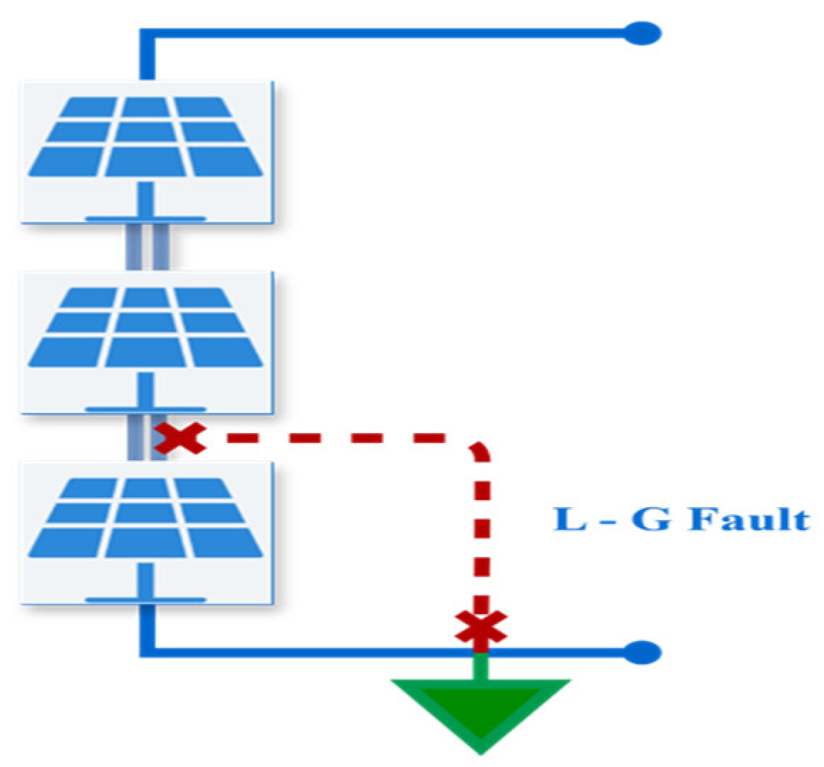
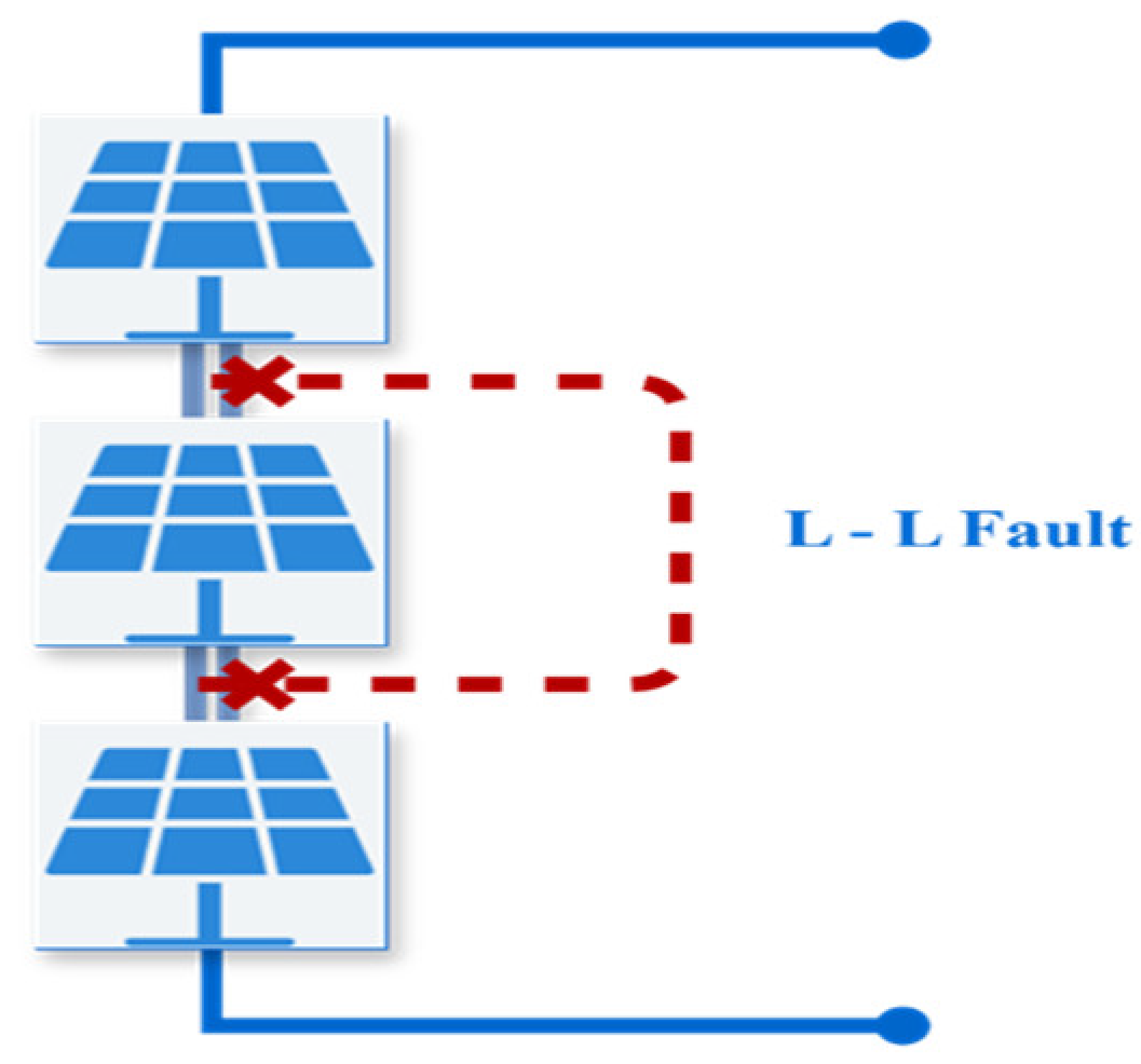
  • To validate the fault-tolerant capabilities of the QZBC using HIL 404 simulation, specifically assessing the system’s ability to maintain continuous power delivery during L-G, L-L faults, and partial shading conditions.
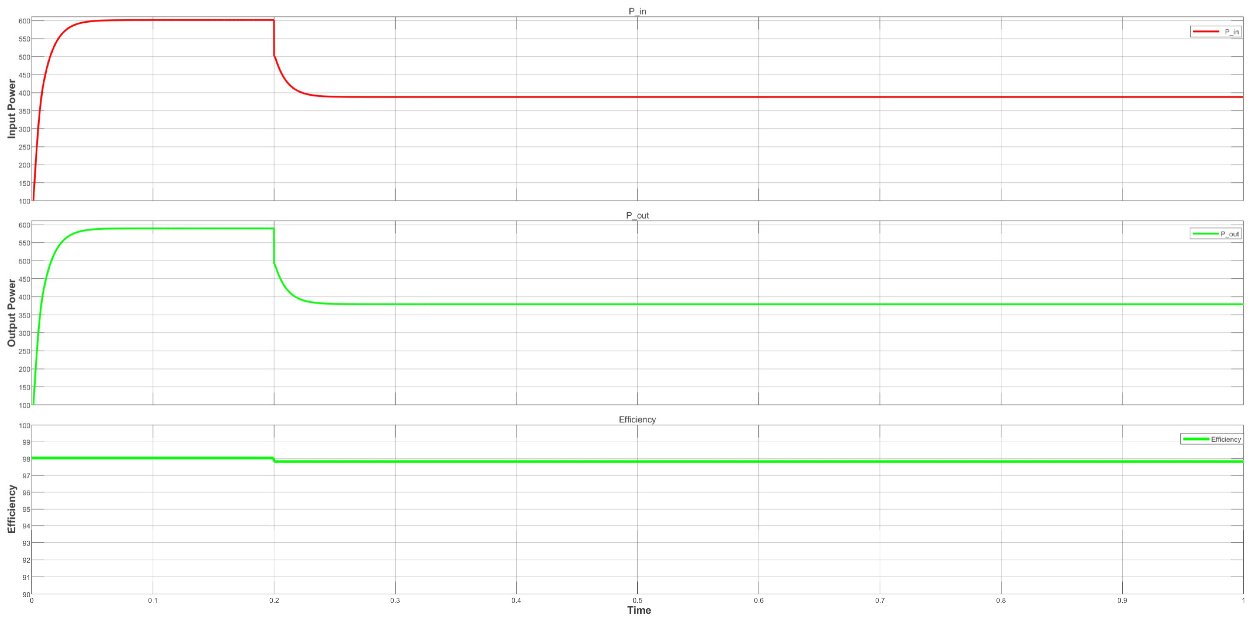
  • To evaluate the efficiency of the PV system integrated with the QZBC under various operating conditions, aiming to achieve high efficiency of the operational PV system even in the presence of different electrical faults.
By addressing these objectives, the study aims to contribute to the development of more resilient and efficient PV systems capable of maintaining performance in the face of common electrical faults.

2. Methodology

This section includes the design, parameter calculation, and real-time validation of a 600 W photovoltaic (PV) system integrated with a quasi-Z-source boost converter (QZBC). The methodology follows an analytical approach using Kirchhoff’s Voltage Law (KVL), volt-second balance principles, and real-time implementation using a Typhoon Hardware-in-the-Loop (HIL) system as shown in Figure 1. The converter is designed to provide a stable 400 V DC output under varying input voltages from 30–100 V, ensuring operation under worst-case conditions.

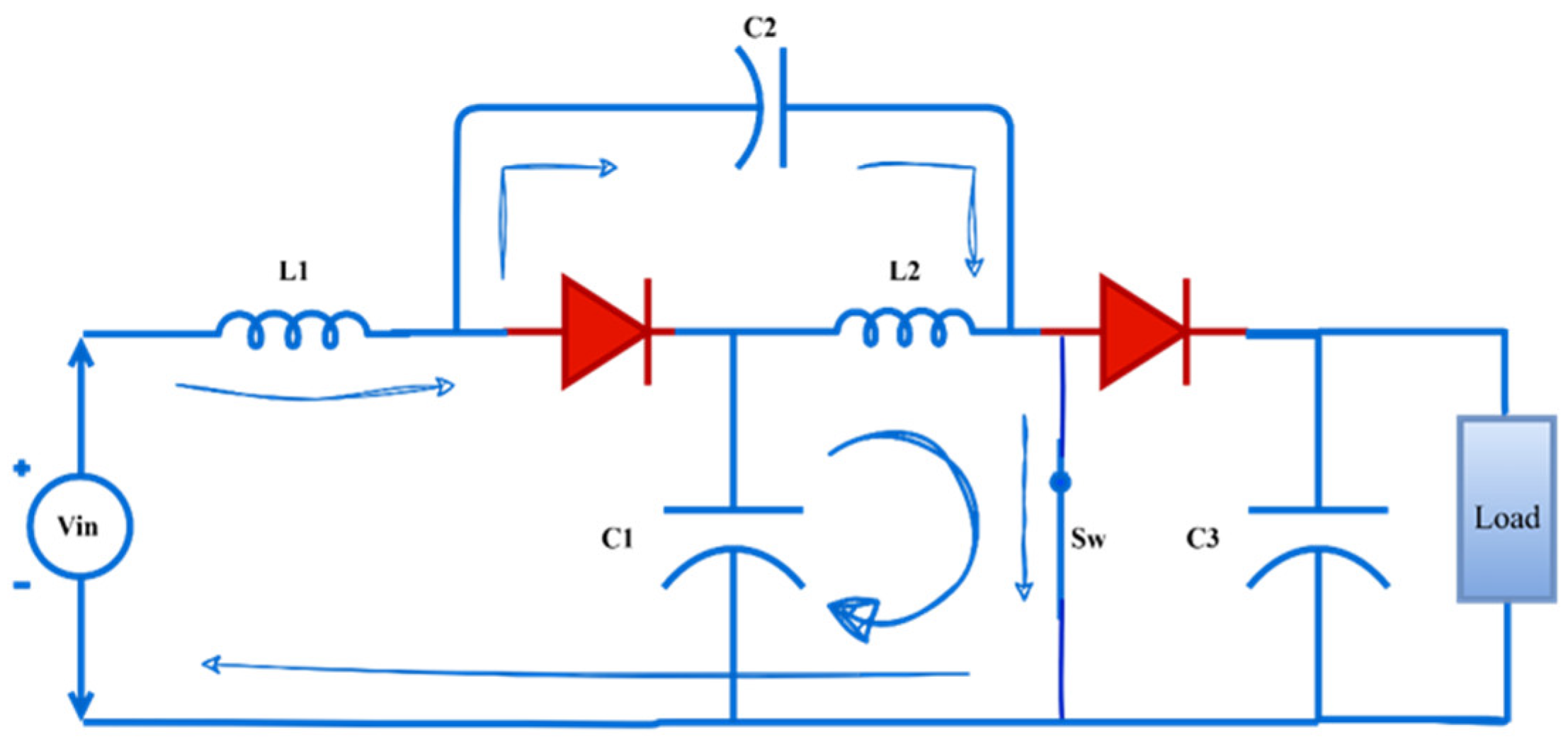
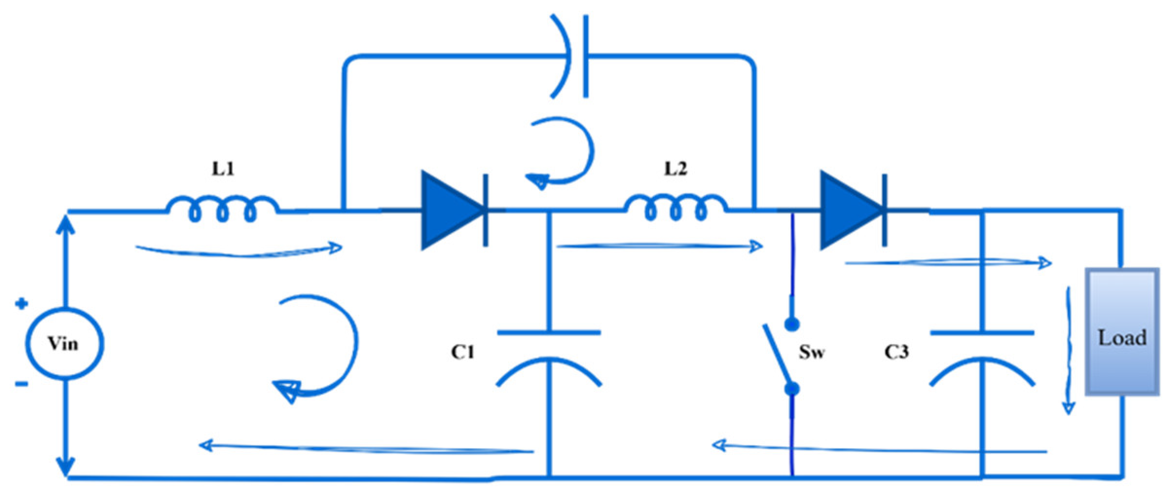
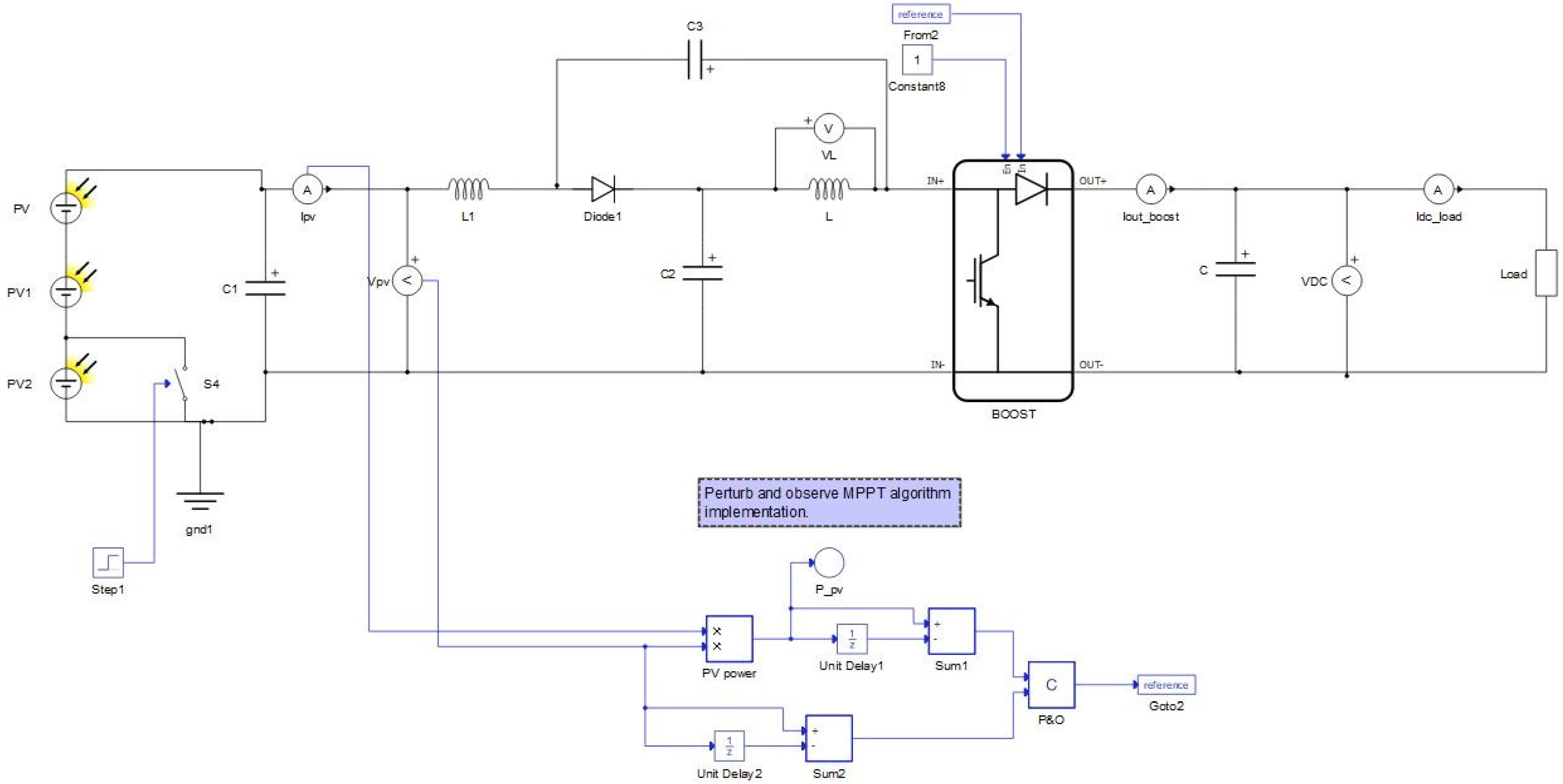
2.1. Operation of Quasi-Z-Source Boost Converter (QZBC)

The QZBC topology consists of an impedance network composed of two inductors (L1 and L2) and two capacitors (C1, C2). In this paper, All the equations of the QZBC have been derived based on Figure 2 and Figure 3. The steady-state waveforms of the quasi-Z-source boost converter during normal operation have been shown in Figure 4. The first waveform in Figure 4 illustrates the switching signal, indicating the timing when the main switch is turned ON, which controls energy flow within the converter. The second waveform depicts the current through Inductor 1, which increases during the switch ON interval as energy is stored in the magnetic field. The third waveform shows the voltage across Capacitor 1, which decreases slightly as it discharges energy to the load and other circuit components. The fourth waveform presents the current through Inductor 2, reflecting the energy transfer from the source through the impedance network to the output. Finally, the fifth waveform represents the voltage across Capacitor 2. Together, these waveforms verify the proper energy storage and transfer mechanisms of the converter in a steady state, demonstrating the boost operation and efficient energy management within the impedance network. The converter operates in two main states:
Shoot-Through Mode (Switch ON): Energy is stored in the inductors, while the diode is reverse-biased;
Non-Shoot-Through Mode (Switch OFF): The stored energy is released to the output, supplying the load.

2.2. KVL Analysis for Different Switching States

Case 1: Switch ON (Shoot-Through Mode)
When the switch is ON, the diode is reverse-biased, and the inductors charge. Applying Kirchhoff’s Voltage Law (KVL) in this mode gives
V i n + V L 1 V C 2 = 0
V L 2 + V c 1 = 0
Case 2: Switch OFF (Non-Shoot-Through Mode)
When the switch is OFF, energy is transferred to the load. Applying KVL gives
V C 2 + V L 2 = 0
V i n V L 1 + V C 1 = 0
V C 1 V L 2 + V O = 0
V i n V L 1 V L 2 + V O = 0

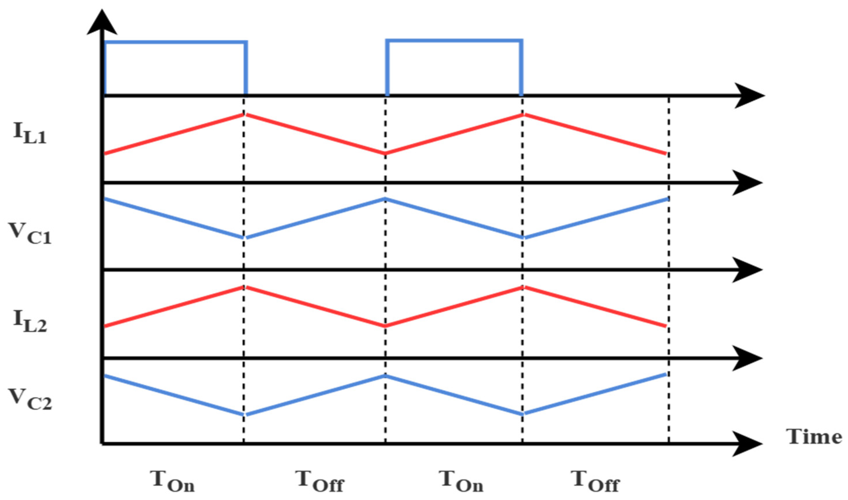
2.3. Volt-Second Balance and Boost Factor Calculation

By applying the volt-second balance principle to Equations (1) and (6), we derived the output voltage equation for QZBC:
( V i n + V C 2 ) T O N = ( V O V i n V L 2 ) T O F F ( V i n + V C 2 ) ( T O N + T O F F ) = V O T O F F V O = ( V i n + V C 2 ) T T O F F
V O = ( V i n + V C 2 ) 1 1 D
By applying the volt-second balance principle to Equations (2) and (3), we derived the output voltage equation for QZBC:
V C 1 T O N = V C 2 T O F F
V C 1 = V C 2 T O F F T O N
V O = 1 1 D V C 2 T O F F T O N
By comparing Equations (7) and (9), the VC2 voltage was derived in terms of input voltage.
1 1 D V C 2 T O F F T O N = ( V i n + V C 2 ) 1 1 D
V C 2 = V i n ( D 1 2 D )
Putting VC2 in Equations (8) and (9) allows the VC1 and Vo equations in terms of Vin and the duty cycle to be obtained as follows:
V C 1 = V i n ( D 1 2 D ) T O F F T O N
V C 1 = V i n ( 1 D 1 2 D )
Using Equations (9) and (10), the output and input voltage relationship was obtained:
V O = 1 1 D T O F F T O N V i n ( D 1 2 D )
V O = V i n ( 1 2 D )
For the inductor, Equation (2) was used:
L 2 d i 2 d t = V C 1
L 1 = L 2 = V C 1 D T S Δ I 2
For the capacitor calculation, during Shoot-Through Mode, the following equations have been used:
I C 2 = I L 1 = I i n
C 2 = I i n D T S Δ V C 2
C 1 = I L 2 D T S Δ V C 1
To find the output, the power balanced formula was used:
P i n = P o
I 0 = I i n ( 1 2 D )

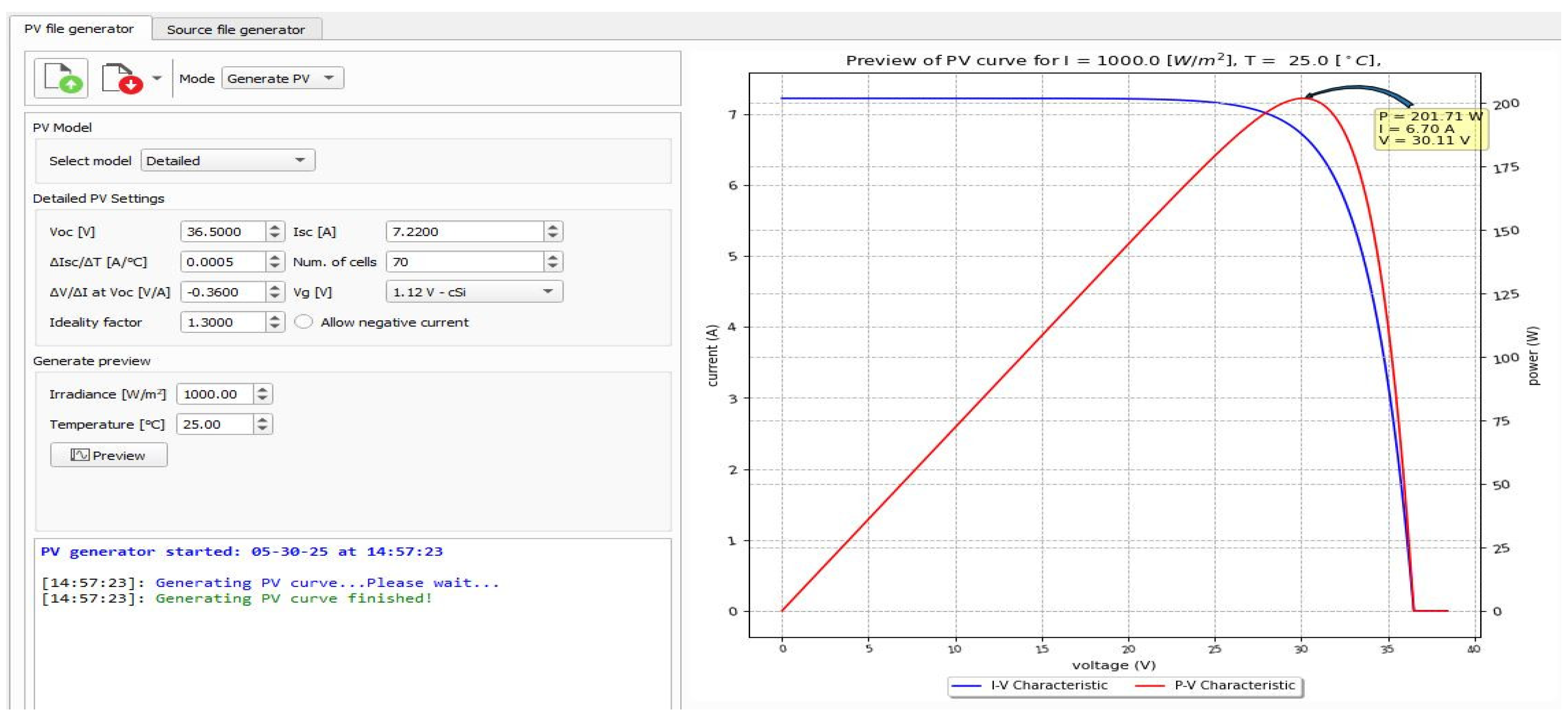
2.4. PV System Configuration

The photovoltaic (PV) system in this study was modeled and implemented in the Typhoon HIL real-time simulation platform for the proposed model as shown in Figure 5, and for the benchmarked model as shown in Figure 6.
A modified PV model was used, designed to deliver a rated power output of 200 W at 30 V and 6.7 A under standard test conditions. This custom configuration was developed in Typhoon HIL using a waveform generator (see Figure 7) to reflect practical operating conditions while maintaining compatibility with the simulated power converter and load. The model was based on the general characteristics of commercial monocrystalline panels, such as the JKM200M-72 produced by Jinko Solar (Jinko Solar Co., Ltd., Shanghai, China) [35]. The modified PV module is available within the SCADA interface of the Typhoon HIL, enabling direct control and monitoring of its parameters during simulation.
The PV system consists of three series-connected modules forming a 3 × 1 configuration. Each module has a power rating of 200 W, with a maximum power point voltage of 30 V and a current of 6.7 A. The total power generated is 600 W, with string voltage varying between 30 V, 60 V, and 90 V based on line-to-ground and line-to-line faults and irradiance conditions as shown in Table 1.

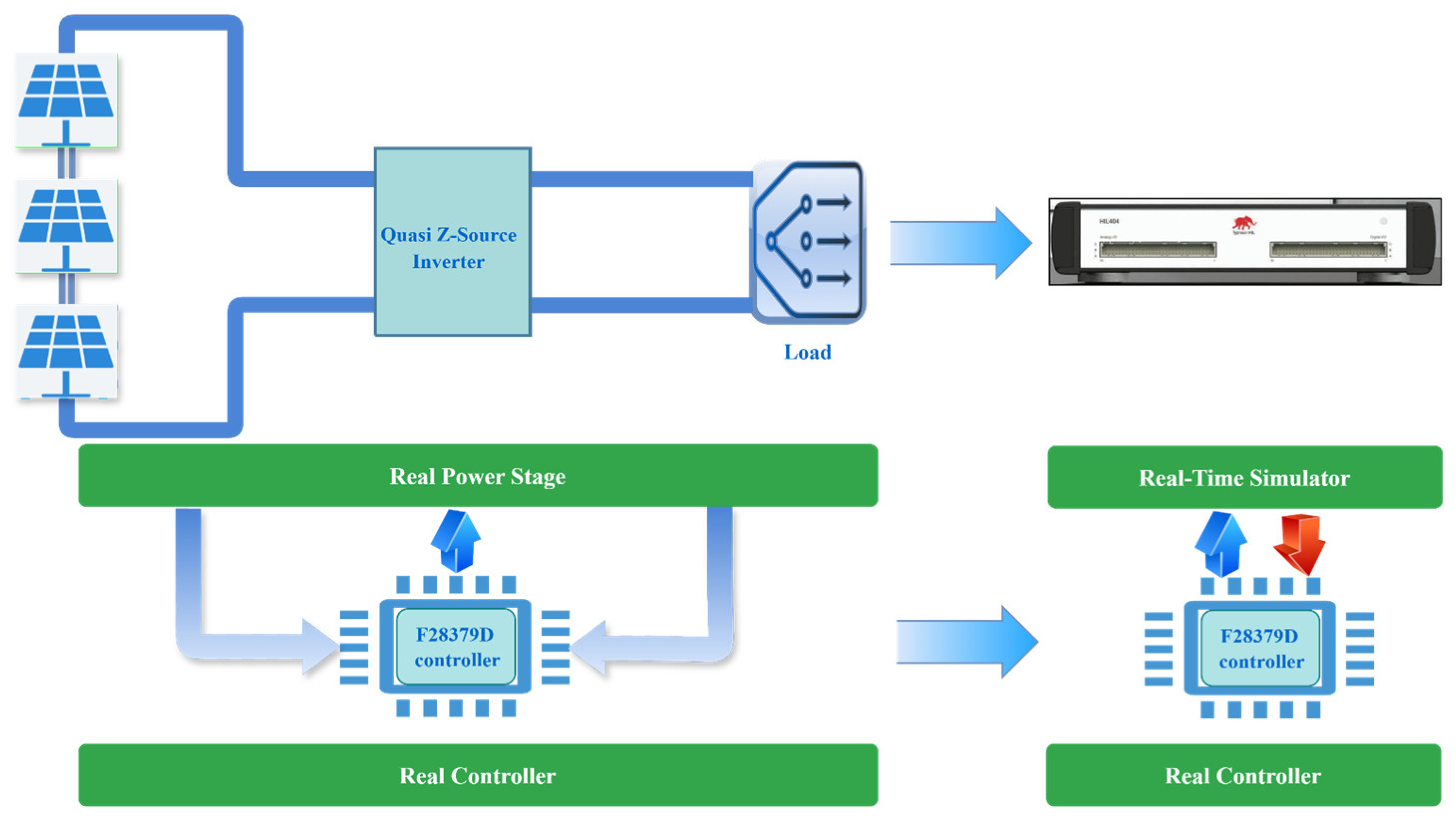
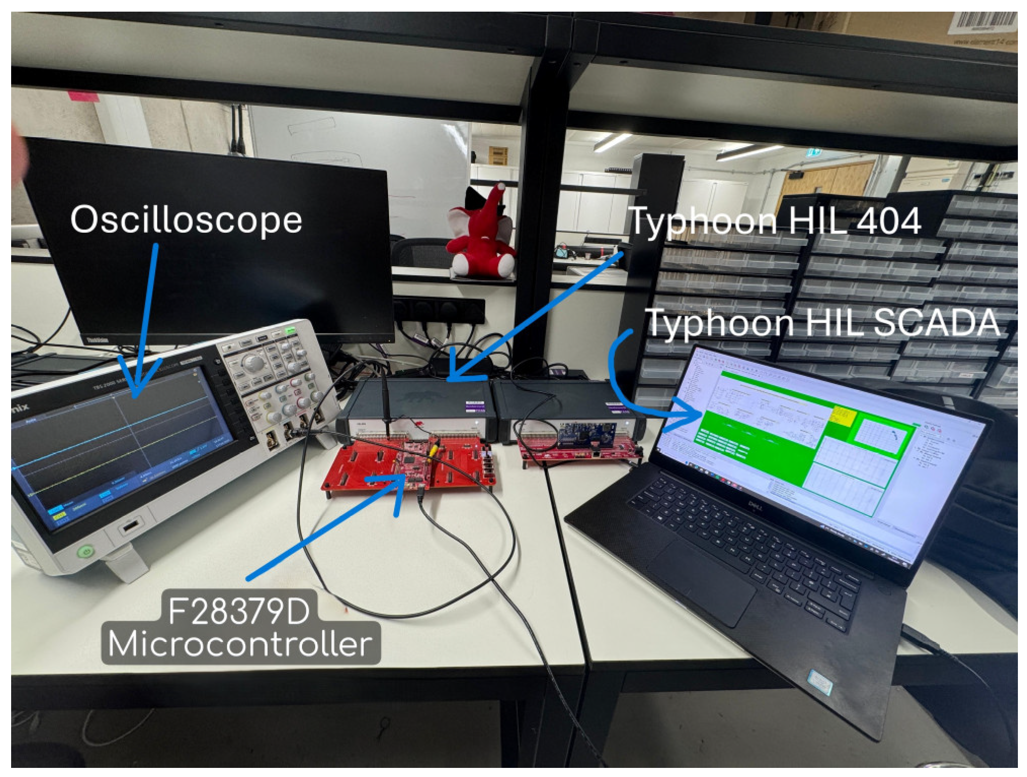
3. Hardware-in-the-Loop (HIL) Setup and Validation

The system was implemented using Typhoon HIL 404 for real-time validation. The setup consisted of
(a)
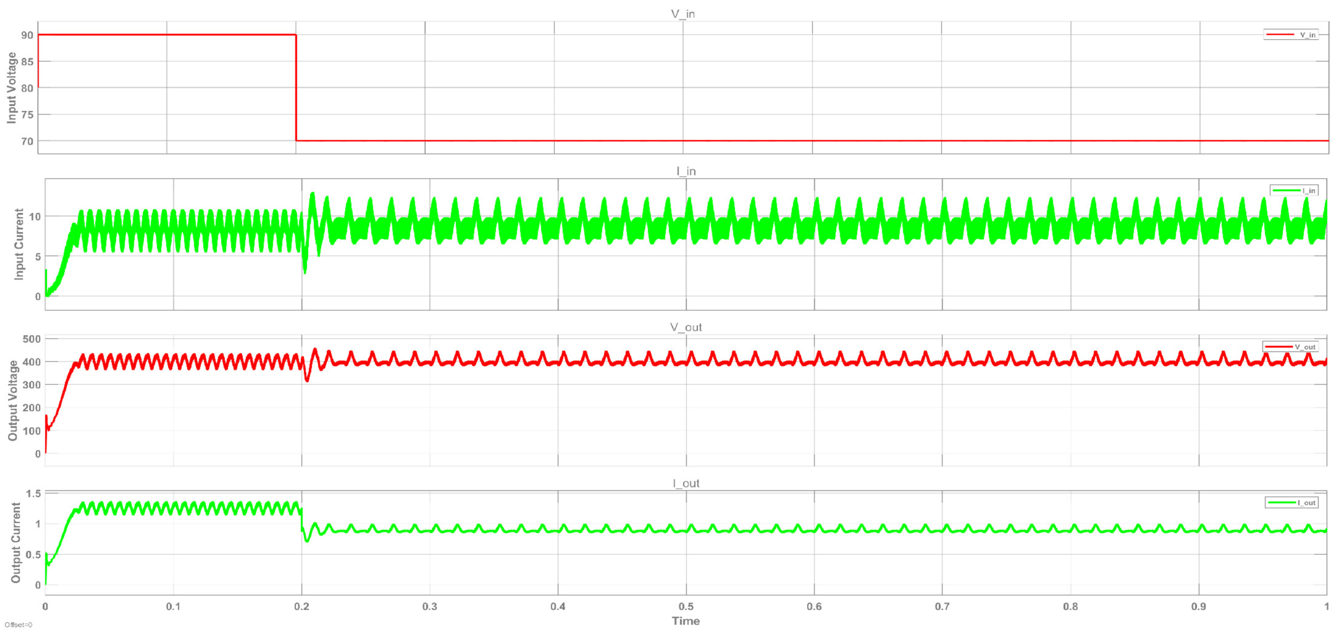
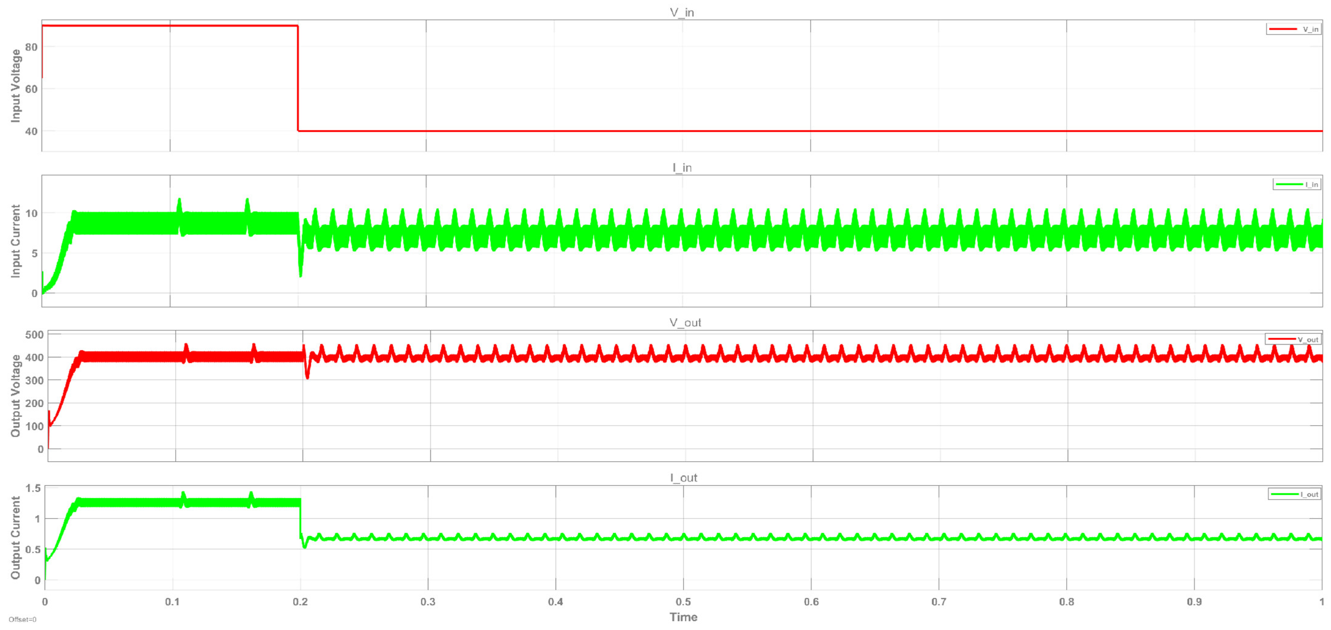
A simulated PV array providing variable input voltages of 30 V, 60 V, and 90 V;
(b)
A digital control unit implementing a pulse-width modulation (PWM) scheme at 1 MHz to regulate QZBC switching;
(c)
A resistive load consuming 600 W at a 400 V output;
(d)
Measurement and monitoring tools to record real-time voltage, current, and efficiency.
A Texas Instruments F28379D microcontroller served as the interface between the Typhoon HIL schematic and the HIL 404 hardware device, enabling accurate signal exchange. The voltage and current signals were conditioned and limited to a range of 0–3 V to ensure compatibility with the microcontroller’s analog input limits and to maintain signal integrity during interfacing, as shown in Figure 8.
The converter performance was evaluated under normal and fault conditions, including line-to-ground (L-G) and line-to-line (L-L) faults. The converter achieved a peak efficiency of 98%, confirming the effectiveness of the QZBC in maintaining stable power delivery under varying input conditions.

4. Results and Discussion

The quasi-Z-source boost converter was simulated in a photovoltaic (PV) system to evaluate its performance under normal and faulty conditions. The simulation results demonstrate that the converter effectively maintained stable voltage-boosting capabilities while handling fluctuations in input power from the PV array.
The simulated PV system consisted of three modules; each rated at 200 W and connected in series to form a 600 W string with a total voltage of 90 V. The performance of the quasi-Z-source boost converter was analyzed under normal and fault conditions to evaluate its efficiency and fault tolerance. For the line-to-ground (L-G) fault scenario, the last module was short-circuited to the ground as shown in Figure 9, causing a temporary drop in output voltage.
However, the system quickly recovered, demonstrating the converter’s capability to suppress transients and maintain stable operation. Similarly, under the line-to-line (L-L) fault condition, where the second module was shorted within the string as shown in Figure 10, the system experienced more significant voltage fluctuations and transient oscillations. Despite the disturbance, the QZBC effectively mitigated voltage instability, allowing the system to recover swiftly as shown in Figure 11. The results highlight the converter’s enhanced fault resilience and improved voltage regulation, making it a robust solution for photovoltaic applications. As shown in Figure 11, from the results, it is noticeable that at 0.5 s, one of the modules experienced a short circuit, causing the input voltage to drop to 70. However, the output voltage remained stable at 400, with some oscillations. This clearly demonstrates that during a line-to-ground fault in this string, the QZBC ensures continuous power delivery from the healthy modules to the system to keep efficiency high.
In large-scale PV systems, a common issue during faults is that the entire string gets disconnected due to its voltage dropping below the operational threshold compared to other strings. This leads to significant power loss and reduced converter efficiency. However, using the quasi-Z-source boost converter (QZBC) with an integrated fault-detection mechanism allows the healthy modules within the string to continue delivering power even under faulty conditions, rather than disconnecting the string completely from the system. This ensures that the system retains a substantial portion of its output, enhancing overall energy utilization. Once the fault is cleared, the converter seamlessly restores the string to its full power delivery without requiring a complete shutdown. This adaptive capability improves fault resilience, minimizes downtime, and optimizes power-generation efficiency in photovoltaic applications.
The data, summarized in Table 2, were collected under standard test conditions (1000 W/m2 irradiance and 25 °C temperature) during normal operation, one module failure, and two module failures, to provide a fair and comprehensive comparison between the two techniques.
Figure 11 shows the results when one module is faulty, while Figure 12 illustrates the case when two modules in the same string are faulty. From Figure 11, it is noticeable that at 0.2 s, one of the modules experienced a short circuit, causing the input voltage to drop to 70. However, the output voltage remained stable at 400 with some oscillations. This clearly demonstrates that during a line-to-ground fault in this string, the QZBC enables the system to continue delivering power from the healthy modules with 400 watts output power and 67% efficiency of its rated power output due to the reduced available input. However, based on the input power that remains available, the converter continues to operate at an efficiency of approximately 98%, as shown in Figure 13, indicating that the power conversion and control remain highly effective under faulty conditions, whereas in the case of benchmarked converters, the entire string is often disconnected if the voltage falls below the minimum threshold, leading to complete power loss from that string. In the proposed method, the required gain during the fault is 0.42 instead of 0.39, which is easy to achieve, whereas in benchmarked cases, a much higher gain of 0.9 is needed. Additionally, if two modules are short-circuited, the input voltage drops to 40, as shown in Figure 12, requiring a gain of 0.47 to maintain 400 V output, to deliver the healthy module 200 watts of power with 33% efficiency of the string, while in benchmarked cases, achieving a 400 V output is almost impossible, as shown in the Table 2.
The methodology involves analytical modeling, worst-case component sizing, and real-time testing using Typhoon HIL. The QZBC successfully boosted the PV voltage to 400 V across a wide range of input conditions. The efficiency of 98% validates the proposed design’s robustness, making it suitable for fault-resilient PV power applications.
Moreover, this paper suggests using GaN FET to enable operation at 1 MHz frequency, which helps in significantly reducing the size of the system while maintaining efficient power delivery. The choice of semiconductor technology significantly affects power density, efficiency, weight, and volume. GaN FET, SiC, and Silicon converters operate at different switching frequencies (1 MHz, 100 kHz, 50 kHz, and 10 kHz), influencing their performance, see Table 3. Higher switching frequencies reduce passive component sizes, increasing power density, while wide bandgap materials (GaN and SiC) achieve lower losses and higher efficiency compared to Silicon. GaN FET offers the highest efficiency (~98%), lowest losses, and smallest volume, making it ideal for compact applications, though it comes at a higher cost. SiC provides a balance of efficiency (~96% at 100 kHz and ~92% at 50 kHz) and cost, with moderate weight and volume, whereas Silicon, despite being cost-effective, has the highest losses, lowest efficiency (~92%), and largest volume. Table 2 below summarizes the key comparisons:
GaN FET converters are ideal for space-constrained PV applications due to their superior power density and efficiency, while SiC offers a cost-efficient compromise. Traditional Silicon technology, although cheaper, suffers from a larger size and lower efficiency, making it less suitable for high-performance applications.
Although employing a GaN-based QZSB converter operating at 1 MHz offers clear benefits in terms of compactness, a fast dynamic response, and improved efficiency, it also introduces several limitations that must be carefully considered when implementing fault-detection algorithms in PV systems. At such high switching frequencies, distinguishing fault-related transients becomes more challenging due to the increased presence of high-frequency noise, which can obscure critical fault signatures in voltage and current waveforms. This necessitates the use of high-speed, high-resolution sensors and fast analog-to-digital converters, thereby increasing both the hardware cost and the computational demands on the control system. The higher operating frequency also requires more sophisticated gate drivers and more precise control algorithms capable of real-time processing, which further increases the system complexity.
Additionally, the design of the printed circuit board (PCB) becomes significantly more sensitive to parasitic inductance and capacitance at 1 MHz, requiring careful layout techniques, additional EMI filtering, and often the use of multilayer boards.

5. Conclusions

This paper demonstrates the design and validation of a quasi-Z-source boost converter (QZBC) for a 600 W photovoltaic (PV) system. The converter successfully stepped-up input voltages of 90 V, 60 V, and 30 V to a stable 400 V DC output, ensuring reliable power conversion under varying input conditions. The system was modeled and analyzed based on worst-case scenarios, and all component values were calculated to meet the system’s performance requirements.
The system was validated using Typhoon HIL, and the results showed that the converter achieved a high efficiency of 98%. The converter effectively maintained stable output even under fault conditions, such as line-to-ground (L-G) and line-to-line (L-L) faults, demonstrating its ability to ensure continuous power delivery from healthy PV panels when part of the array is affected by faults.
This study highlights the potential of the fault-detection mechanism to not significantly disrupt the energy-conversion process, making the overall system suitable for practical deployment in PV applications where both efficiency and fault resilience are critical.
Future research will focus on refining the control strategies to further optimize system performance and conducting real-world testing to validate the proposed design’s practical feasibility in actual PV installations.

Author Contributions

Conceptualization, B.A. and P.T.; Software, B.A. and A.A.; Validation, B.A. and P.T.; Formal analysis, M.S.A.A.S. and A.A.; Investigation, M.M. and P.T.; Resources, M.S.A.A.S.; Data curation, B.A. and A.A.; Writing—original draft, B.A.; Visualization, M.S.A.A.S.; Supervision, P.T.; Project administration, M.M. All authors have read and agreed to the published version of the manuscript.

Funding

This research received no external funding. The APC was fully waived by the editorial office of MDPI.

Data Availability Statement

The original contributions presented in this study are included in the article. Further inquiries can be directed to the corresponding author.

Conflicts of Interest

The authors declare no conflict of interest.

References

  1. Rahim, A.; Agarwal, S.; Gupta, G.; Singh, R.; Malik, P.K. Efficient Use of Renewable Solar Energy Resource for Electric Vehicles: Opportunities and Challenges. Eng. Rep. 2025, 7, e70007. [Google Scholar] [CrossRef]
  2. Novas, N.; Garcia, R.M.; Camacho, J.M.; Alcayde, A. Advances in solar energy towards efficient and sustainable energy. Sustainability 2021, 13, 6295. [Google Scholar] [CrossRef]
  3. Madeti, S.R.; Singh, S. A comprehensive study on different types of faults and detection techniques for solar photovoltaic system. Sol. Energy 2017, 158, 161–185. [Google Scholar] [CrossRef]
  4. Aghaei, M.; Fairbrother, A.; Gok, A.; Ahmad, S.; Kazim, S.; Lobato, K.; Oreski, G.; Reinders, A.; Schmitz, J.; Theelen, M. Review of degradation and failure phenomena in photovoltaic modules. Renew. Sustain. Energy Rev. 2022, 159, 112160. [Google Scholar] [CrossRef]
  5. Livera, A.; Theristis, M.; Makrides, G.; Georghiou, G.E. Recent advances in failure diagnosis techniques based on performance data analysis for grid-connected photovoltaic systems. Renew. Energy 2019, 133, 126–143. [Google Scholar] [CrossRef]
  6. Obi, M.; Bass, R. Trends and challenges of grid-connected photovoltaic systems—A review. Renew. Sustain. Energy Rev. 2016, 58, 1082–1094. [Google Scholar] [CrossRef]
  7. Kilikevičienė, K.; Matijošius, J.; Kilikevičius, A.; Jurevičius, M.; Makarskas, V.; Caban, J.; Marczuk, A. Research of the energy losses of photovoltaic (PV) modules after hail simulation using a newly-created testbed. Energies 2019, 12, 4537. [Google Scholar] [CrossRef]
  8. Obatola, S.O. Reliability Overview of Grid-Connected Solar PV System: A Review. Arch. Adv. Eng. Sci. 2024, 1–10. [Google Scholar] [CrossRef]
  9. Hasan, M.; Hossain, S.; Mofijur, M.; Kabir, Z.; Badruddin, I.A.; Yunus Khan, T.; Jassim, E. Harnessing solar power: A review of photovoltaic innovations, solar thermal systems, and the dawn of energy storage solutions. Energies 2023, 16, 6456. [Google Scholar] [CrossRef]
  10. Karthik, K.; Ponnambalam, P. Design and implementation of time-based fault tolerance technique for solar PV system reliability improvement in different applications. Sci. Rep. 2025, 15, 7377. [Google Scholar] [CrossRef]
  11. Malik, A.; Haque, A.; Kurukuru, V.B.; Mekhilef, S. Fault-resilient control of parallel PV inverters using multi-agent twin-delayed deep deterministic policy gradient approach. Int. J. Circuit Theory Appl. 2024, 52, 3230–3254. [Google Scholar] [CrossRef]
  12. Ali, B.; Ashraf, A.; Alsunjury, M.S.; Tricoli, P. Grid-Connected PV System’s Voltage Stabilisation Using Model Predictive Control Based MPPT During Abrupt Changes in Irradiance. In Proceedings of 2024 IEEE 18th International Conference on Compatibility, Power Electronics and Power Engineering, (CPE-POWERENG), Gdynia, Poland, 24–26 June 2024; pp. 1–6. [Google Scholar]
  13. Shafiullah, M.; Ahmed, S.D.; Al-Sulaiman, F.A. Grid integration challenges and solution strategies for solar PV systems: A review. IEEE Access 2022, 10, 52233–52257. [Google Scholar] [CrossRef]
  14. Lawani, A.; Adeleke, T.; Osuizugbo, I. Solar Photovoltaic Systems: A Review of Risks, Fault Detection, and Mitigation Strategies. In Proceedings of 2024 IEEE 5th International Conference on Electro-Computing Technologies for Humanity (NIGERCON), Ado-Ekiti, Nigeria, 26–28 November 2024; pp. 1–5. [Google Scholar]
  15. Meraj, M.; Rahman, S.; Husain, S.; Ben-Brahim, L.; Iqbal, A. New switching technique for quasi-z-source resonant converter. In Proceedings of 2018 IEEE 12th International Conference on Compatibility, Power Electronics and Power Engineering (CPE-POWERENG 2018), Doha, Qatar, 10–12 April 2018; pp. 1–5. [Google Scholar]
  16. Li, Y.; Anderson, J.; Peng, F.Z.; Liu, D. Quasi-z-source inverter for photovoltaic power generation systems. In Proceedings of 2009 Twenty-Fourth Annual IEEE Applied Power Electronics Conference and Exposition, Washington, DC, USA, 15–19 February 2009; pp. 918–924. [Google Scholar]
  17. Liu, Y.; Abu-Rub, H.; Ge, B. Z-source\/quasi-z-source inverters: Derived networks, modulations, controls, and emerging applications to photovoltaic conversion. IEEE Ind. Electron. Mag. 2014, 8, 32–44. [Google Scholar] [CrossRef]
  18. Meraj, M.; Iqbal, A.; Al-Emadi, N.; Rahman, S.; Bhaskar, M.S. Novel PWM Technique for Quasi Switched Boost Converter for the Nano-grid Applications. In Proceedings of 2019 IEEE 28th International Symposium on Industrial Electronics (ISIE), Vancouver, BC, Canada, 12–14 June 2019; pp. 2659–2664. [Google Scholar]
  19. Ge, B.; Abu-Rub, H.; Peng, F.Z.; Lei, Q.; De Almeida, A.T.; Ferreira, F.J.; Sun, D.; Liu, Y. An energy-stored quasi-Z-source inverter for application to photovoltaic power system. IEEE Trans. Ind. Electron. 2012, 60, 4468–4481. [Google Scholar] [CrossRef]
  20. Li, Y.; Jiang, S.; Cintron-Rivera, J.G.; Peng, F.Z. Modeling and control of quasi-Z-source inverter for distributed generation applications. IEEE Trans. Ind. Electron. 2012, 60, 1532–1541. [Google Scholar] [CrossRef]
  21. Abid, A.; Bakeer, A.; Zellouma, L.; Bouzidi, M.; Lashab, A.; Rabhi, B. Low computational burden predictive direct power control of quasi Z-source inverter for grid-tied PV applications. Sustainability 2023, 15, 4153. [Google Scholar] [CrossRef]
  22. Monjo, L.; Sainz, L.; Mesas, J.J.; Pedra, J. Quasi-Z-source inverter-based photovoltaic power system modeling for grid stability studies. Energies 2021, 14, 508. [Google Scholar] [CrossRef]
  23. Abdullah, D. Comparative Analysis of SIC and GAN-Based Power Converters in Renewable Energy Systems. Natl. J. Electr. Mach. Power Convers. 2025, 1, 11–20. [Google Scholar]
  24. Kabir, M.R. Comparison of Si and GaN Based Converter for PV Application Using Various MPPT Methods. Master’s Thesis, The University of Toledo, Toledo, OH, USA, 2016. [Google Scholar]
  25. Rodríguez-Benítez, O.M.; Ponce-Silva, M.; Aquí-Tapia, J.A.; Claudio-Sánchez, A.; Vela-Váldes, L.G.; Lozoya-Ponce, R.E.; Cortés-García, C. Comparative performance and assessment study of a current-fed DC-DC resonant converter combining Si, SiC, and GaN-based power semiconductor devices. Electronics 2020, 9, 1982. [Google Scholar] [CrossRef]
  26. Osmani, K.; Haddad, A.; Lemenand, T.; Castanier, B.; Alkhedher, M.; Ramadan, M. A critical review of PV systems’ faults with the relevant detection methods. Energy Nexus 2023, 12, 100257. [Google Scholar] [CrossRef]
  27. Faris Amiri, A.; Kichou, S.; Oudira, H.; Chouder, A.; Silvestre Bergés, S. Fault detection and diagnosis of a photovoltaic system based on deep learning using the combination of a Convolutional Neural Network (CNN) and Bidirectional Gated Recurrent Unit (Bi-GRU). Sustainability 2024, 16, 1012. [Google Scholar] [CrossRef]
  28. Tariq, M.; Rihan, M.; Ayan, M. A comprehensive review on the application of recently introduced optimization techniques obtaining maximum power in the solar PV System. Renew. Energy Focus 2024, 49, 100564. [Google Scholar]
  29. Barath, J.N.; Soundarrajan, A.; Stepenko, S.; Husev, O.; Vinnikov, D.; Nguyen, M.-K. Topological review of quasi-switched boost inverters. Electronics 2021, 10, 1485. [Google Scholar] [CrossRef]
  30. Samano-Ortega, V.; Padilla-Medina, A.; Bravo-Sanchez, M.; Rodriguez-Segura, E.; Jimenez-Garibay, A.; Martinez-Nolasco, J. Hardware in the loop platform for testing photovoltaic system control. Appl. Sci. 2020, 10, 8690. [Google Scholar] [CrossRef]
  31. Youssef, A.; El Telbany, M.; Zekry, A. Reconfigurable generic FPGA implementation of fuzzy logic controller for MPPT of PV systems. Renew. Sustain. Energy Rev. 2018, 82, 1313–1319. [Google Scholar] [CrossRef]
  32. Toosi, H.E.; Merabet, A.; Ghias, A.M.; Swingler, A. Central power management system for hybrid PV/battery AC-bus microgrid using typhoon HIL. In Proceedings of 2019 IEEE 28th International Symposium on Industrial Electronics (ISIE), Vancouver, BC, Canada, 12–14 June 2019; pp. 1053–1058. [Google Scholar]
  33. Salunke, M.; Tiwari, D. Modeling and Real-Time Simulation of Photovoltaic Plant Using Typhoon HIL. In Advances in Renewable Energy and Electric Vehicles: Select Proceedings of AREEV 2020; Springer: New York, NY, USA, 2021; pp. 331–341. [Google Scholar]
  34. Typhoon HIL. HIL Simulator 404. Available online: https://www.typhoon-hil.com/products/hil-simulator/hil404/ (accessed on 11 March 2025).
  35. Typhoon HIL. PV Panel Settings. Available online: https://www.typhoon-hil.com/documentation/typhoon-hil-software-manual/References/pv_panel_settings.html (accessed on 11 March 2025).
  36. Miao, W.; Luo, Y.; Liu, Y.; Wang, F.; Zhi, F.; Zhou, X. Detection of line-to-ground and line-to-line faults based on fault voltage analysis in PV system. In Proceedings of 2022 7th International Conference on Power and Renewable Energy (ICPRE), Shanghai, China, 23–26 September 2022; pp. 424–429. [Google Scholar]
  37. Hajji, M.; Yahyaoui, Z.; Mansouri, M.; Nounou, H.; Nounou, M. Fault detection and diagnosis in grid-connected PV systems under irradiance variations. Energy Rep. 2023, 9, 4005–4017. [Google Scholar] [CrossRef]
  38. Rasul, A.; Teixeira, R.; Baptista, J. Silicon Carbide Converter Design: A Review. Energies 2025, 18, 2140. [Google Scholar] [CrossRef]
  39. Alves, L.F.; Gomes, R.C.; Lefranc, P.; Pegado, R.D.A.; Jeannin, P.-O.; Luciano, B.A.; Rocha, F.V. SIC power devices in power electronics: An overview. In Proceedings of 2017 Brazilian Power Electronics Conference (COBEP), Juiz de Fora, MG, Brazil, 19–22 November 2017; pp. 1–8. [Google Scholar]
  40. Hazra, S.; De, A.; Cheng, L.; Palmour, J.; Schupbach, M.; Hull, B.A.; Allen, S.; Bhattacharya, S. High switching performance of 1700-V, 50-A SiC power MOSFET over Si IGBT/BiMOSFET for advanced power conversion applications. IEEE Trans. Power Electron. 2015, 31, 4742–4754. [Google Scholar]
  41. Sadeghian, O.; Oshnoei, A.; Mohammadi-Ivatloo, B.; Vahidinasab, V.; Anvari-Moghaddam, A. A comprehensive review on electric vehicles smart charging: Solutions, strategies, technologies, and challenges. J. Energy Storage 2022, 54, 105241. [Google Scholar] [CrossRef]
  42. He, N.; Chen, M.; Wu, J.; Zhu, N.; Xu, D. 20-kW zero-voltage-switching SiC-MOSFET grid inverter with 300 kHz switching frequency. IEEE Trans. Power Electron. 2018, 34, 5175–5190. [Google Scholar] [CrossRef]
Figure 1. Circuit and block diagram of quasi-Z-source boost converter (QZBC)-based photovoltaic (PV) power systems.
Electronics 14 02522 g001
Figure 2. Equivalent circuit of QZBC with continuous current input at Shoot-Through Mode.
Electronics 14 02522 g002
Figure 3. Equivalent circuit of QZBC with continuous current input at Non-Shoot-Through Mode.
Electronics 14 02522 g003
Figure 4. Steady-state waveforms of the quasi-z-source boost converter.
Electronics 14 02522 g004
Figure 5. Schematic diagram of the proposed model in Typhoon HIL.
Electronics 14 02522 g005
Figure 6. Schematic diagram of the benchmarked model in Typhoon HIL.
Electronics 14 02522 g006
Figure 7. Characteristics of modified PV model in Typhoon HIL.
Electronics 14 02522 g007
Figure 8. Hardware-in-the-loop setup of the quasi-Z-source boost converter (QZBC)-based photovoltaic (PV) power system.
Electronics 14 02522 g008
Figure 9. Line-to-ground fault in PV string.
Electronics 14 02522 g009
Figure 10. Line-to-line fault in PV string.
Electronics 14 02522 g010
Figure 11. Results of the proposed technique during one module failure were tested at 1000 W/m2 irradiance and 25 °C temperature.
Electronics 14 02522 g011
Figure 12. Results of proposed technique during two modules’ failure were tested at 1000 W/m2 irradiance and 25 °C temperature.
Electronics 14 02522 g012
Figure 13. Input power vs. output power, and efficiency of the PV system.
Electronics 14 02522 g013
Table 1. Specification of the 3 × 1 PV system and QZSB converter’s components.
ParametersSpecification
Each module maximum power (Pm)200 W
Open circuit voltage (Voc)36.5 V
Voltage at maximum power (Vmax)30 V
Short circuit current (Isc)7.22 A
Current at maximum power (Imax)6.7 A
No. of cells per module70
Ideality factor1.300
Irradiance1000 W/m2
Temperature25 °C
L12.8 mH
L22.8 mH
C15.0 µF
C25.0 µF
C35.0 µF
Ro320 Ω
Table 2. Comparison of QZSB converter with benchmarked boost converters connected with 3 × 1 PV system [36,37].
ConditionVinVoGainQZSB ConverterBenchmarked Converters
----DMPPT
Compatibility
EfficiencyDMPPT
Compatibility
Efficiency
Normal90 V400 V4.440.38Yes98%0.77Yes96%
One module faulty60 V400 V6.60.41Yes89%0.82Limited67%
Two modules faulty30 V400 V13.30.46Yes77%0.93Limited67%
Table 3. Qualitative Comparison of GaN FET, Silicon Carbide, and Silicon Converters for PV systems [23,24,25,38,39,40,41,42].
ParameterGaN FET (1 MHz)SiC (100 kHz)SiC (50 kHz)Silicon (10 kHz)
Switching Frequency1 MHz100 kHz50 kHz10 kHz
Power DensityHighestHigherMediumLowest
Efficiency~98%~96%~92%~92%
LossesLowestMediumhigherHighest
WeightLightestModerateHigherHeaviest
VolumeSmallestMediumMedium+Largest
Thermal ManagementLeast requiredModerateCriticalMost required
CostHighMediumMedium+Low
Disclaimer/Publisher’s Note: The statements, opinions and data contained in all publications are solely those of the individual author(s) and contributor(s) and not of MDPI and/or the editor(s). MDPI and/or the editor(s) disclaim responsibility for any injury to people or property resulting from any ideas, methods, instructions or products referred to in the content.

