1. Introduction
As the central hub of the spacecraft data management system, the onboard solid-state recorder (O-SSR) [
1,
2,
3,
4] plays a critical and irreplaceable role in modern space missions. It must efficiently collect, classify, store, and schedule data from multiple sources in real time. At the same time, data integrity and reliability must be ensured under extreme space environments [
5].
As spacecraft systems become more complex, modern O-SSRs face unprecedented technical challenges. Large volumes of high-data-rate information must be processed. These data streams come from dozens or even hundreds of sources, including scientific payloads [
6,
7], platform subsystems [
8], and environmental monitoring instruments [
9]. Additionally, long-term reliable storage must be maintained for deep space exploration and other specialized missions.
From a system-level perspective, storage performance has become a key factor limiting overall spacecraft capabilities. Recent technological advancements show clear asymmetry. The storage density has improved significantly with 3D NAND stacking technology [
10], reaching the terabyte level. However, progress in radiation resistance and high-speed access remains slow. These factors directly impact the spacecraft operational lifespan and scientific observation capabilities. In deep space exploration, O-SSR reliability is often the decisive factor in mission success or failure.
NAND flash is widely used as the core storage medium in O-SSRs. Its performance has been greatly improved with advancements in non-volatile double data rate (NV-DDR) interface technology [
11]. The latest spaceborne NAND flash storage interfaces support reference clock frequencies of up to 500 MHz. Using double data rate technology, each data I/O interface can achieve instantaneous transfer speeds of up to 1000 Mbps.
In the harsh space radiation environment, data reliability is severely threatened. Single-event effects (SEEs) [
12] are the main causes of data errors in O-SSRs. To protect data integrity, error correction coding (ECC) [
13] is widely used in spaceborne storage systems. Currently, ECC methods for space applications mainly include Reed–Solomon (RS) codes [
14,
15], Hamming codes [
16], and low-density parity check (LDPC) codes [
17]. RS codes are commonly chosen due to their strong error correction capabilities and efficient implementation.
The RS(256,252) and RS(255,223) codes have been used in space missions. RS(256,252) is valued for its low algorithmic complexity and simple implementation. It supports a maximum operating frequency of 400 MHz [
18], making it suitable for high-speed data transmission. However, it can only correct two symbol errors, which limits its effectiveness in high-radiation environments. RS(255,223) offers much better error correction, correcting up to 16 symbol errors. This makes it ideal for space missions that require high reliability. However, its higher algorithmic complexity reduces its maximum operating frequency to only 120 MHz [
19]. As a result, it cannot meet the speed requirements of NV-DDR high-speed storage interfaces.
To improve both radiation resistance and high-speed access in O-SSRs, further research is urgently needed. The RS(255,223) encoder architecture must be optimized. The data processing speed should be increased, enabling its application in NV-DDR storage systems.
In response to these bottlenecks, recent research has achieved progress in addressing the following issues:
In the field of RS(255,223) encoder architecture optimization, an innovative coefficient-by-coefficient update architecture was proposed by Silva et al. [
19]. This method introduced a parameter pre-computation mechanism. First, intermediate parameters were generated using input symbols and the least significant coefficient. Then, a distributed update strategy was applied, dividing the coefficient update process into parallel operations across 32 registers. Through logic restructuring, the critical path delay was significantly reduced. As a result, an operating frequency of 120 MHz was achieved, doubling the performance of traditional architectures. However, as the interface rates in modern O-SSRs continue to reach the tens-of-Gbps range, this performance level remains insufficient for practical applications.
To address this challenge, a parallel processing architecture based on algorithm simplification was proposed by Zhan [
20]. This approach employed a timing compression technique to merge multi-cycle operations into a single clock cycle. At the same time, spatial parallelism was used to enhance the system throughput. When the bit width was expanded to 256 bits (with 32 parallel lanes), a theoretical throughput of 8.192 Gbps was achieved. However, several design challenges arose. Increased routing congestion caused timing degradation. Logic resource consumption grew at a superlinear rate. More importantly, the clock frequency decreased as parallelism increased. This limitation makes bit-width expansion alone an unsustainable solution in meeting performance requirements.
These research findings highlight the core challenges in optimizing RS encoders. Serial architectures are inherently constrained by their algorithmic structures, limiting the degree of pipelining that can be applied, while parallel solutions face resource efficiency bottlenecks.
To overcome these limitations and enhance the radiation resistance, a novel interleaved pipelined architecture is proposed in this study for the implementation of the RS(255,223) encoder. Significant performance improvements have been achieved through both algorithmic optimization and structural innovation.
At the algorithmic level, interleaving techniques [
21] are introduced to enable the RS encoder to protect against multi-bit upset (MBU) [
22]. This mechanism ensures that MBU-induced burst errors are dispersed across multiple parity sequences, significantly enhancing the system’s radiation resistance.
On the architectural side, the limitations of traditional RS encoders are successfully overcome. The interleaving technique is integrated into the pipeline. As a result, the pipeline is extended to 36 stages without causing any stalls. A dynamic parameter-switching mechanism allows a single encoding module to efficiently process four interleaved parity sequences. Each pipeline stage is configured with four identical computation parameters, enabling automatic switching between different parity sequences after processing each input symbol. As a result, the processing interval between adjacent symbols is extended to three clock cycles, ensuring sufficient timing margins for deep pipeline construction. Additionally, a continuous data flow is maintained, preventing pipeline stalls. Within a single encoding module, 4 × 223 symbols are continuously input, with every two symbols per three-symbol interval mapped to an RS codeword. Ultimately, four interleaved parity sequences are alternately output, achieving both enhanced performance and improved reliability.
In summary, both the operating frequency of the encoder and the radiation resistance of the encoded data are significantly improved in this study. In contrast to traditional approaches, where interleaving operations are performed only after encoding, the interleaving technique is innovatively integrated into the pipelining process. Consequently, a 36-stage pipeline is successfully developed. By dispersing multi-bit upsets across multiple parity sequences, the interleaving approach is shown to dramatically enhance the data radiation resistance.
Experimental results indicate that, with an 8-bit symbol size, an operating frequency of 450 MHz is achieved by a single encoder, with the data processing rate reaching 3.03 Gbps. Theoretical analysis suggests that this hybrid encoding strategy can improve the error correction capability by approximately four times.
The remainder of this paper is organized as follows.
Section 1 provides a detailed review and description of RS(255,223), including its algorithmic foundations and a basic hardware implementation.
Section 2 presents the proposed 36-stage pipelined architecture with interleaving techniques.
Section 3 discusses the experimental results, and
Section 4 concludes the paper.
3. Interleaved Pipelined Architecture
In traditional architectures, long dependency chains limit the ability to divide the pipeline into more stages. This results in a longer critical path, making it difficult to use higher clock frequencies and ultimately reducing the throughput.
To improve both the radiation tolerance and throughput, interleaving techniques have been introduced into the RS encoder. In the conventional design, the steps of receiving the input symbol , computing parameter F, computing parameter T, and updating the parameter matrix R are handled in separate pipeline stages. However, there is a four-cycle dependency between parameter F and matrix R. These cycles include the computation of F, the computation of T, the update of R, and the write-back of to the first stage for the next F computation. As a result, the pipeline has to be stalled to wait for to be written back, which negatively impacts the performance.
To solve this problem, interleaving is applied to the pipeline design. The input sequence
(where
to 891) is divided into four interleaved sequences:
These interleaved sequences are then sequentially fed to the encoder for parallel processing. By interleaving the data, independent input streams are introduced into the pipeline. This allows the encoder to continue working on other data while waiting for dependencies to be resolved, reducing the idle time caused by the delay in writing back . Each of the four interleaved streams , , , and takes turns passing through the pipeline stages. This arrangement ensures that, for any given stream (where ), there is a three-cycle interval between the processing of two consecutive symbols, and . When one stream reaches the stage that requires the updated , the three-cycle gap guarantees that has already been updated and written back to the input stage of the pipeline. For example, when is at the stage of updating matrix R, is in the stage of computing parameter T, is computing parameter F, and is receiving the input symbol. At the next active clock edge, , , , and are advanced to the next pipeline stage. Meanwhile, the updated is written back to the first stage, and is introduced into the pipeline. At this point, uses the returned from the later stage. This staggered scheduling hides the delay between F and R, allowing the pipeline to run without stalling and improving the throughput. Since the interleaved streams are independent, the pipeline can be made deeper, and the system can run at a higher clock frequency. As a result, the overall data processing speed increases.
Radiation tolerance is also improved through this interleaved design. In conventional schemes, only up to 16 consecutive symbol errors can be corrected. However, in the proposed approach, the encoder output is interleaved across four error-correcting sequences, allowing up to 64 consecutive symbol errors to be corrected simultaneously. Although the RS(255,223) code itself is capable of correcting up to 16 symbol errors, the interleaved pipeline structure is designed to map each input stream into four separate RS codewords. As a result, even if a burst of 64 consecutive symbols is affected by a multi-bit upset, data recovery can still be achieved, provided that no individual codeword exceeds its 16-symbol correction threshold. As shown in
Figure 2, a total of 892 symbols are input into the proposed architecture. Subsequently, 892 information symbols and 128 parity symbols are output. The output symbols are distributed among four error-correcting sequences, which are indicated in red, green, blue, and yellow, respectively. It can be observed that the input sequence is interleaved and partitioned into four distinct error-correcting streams.
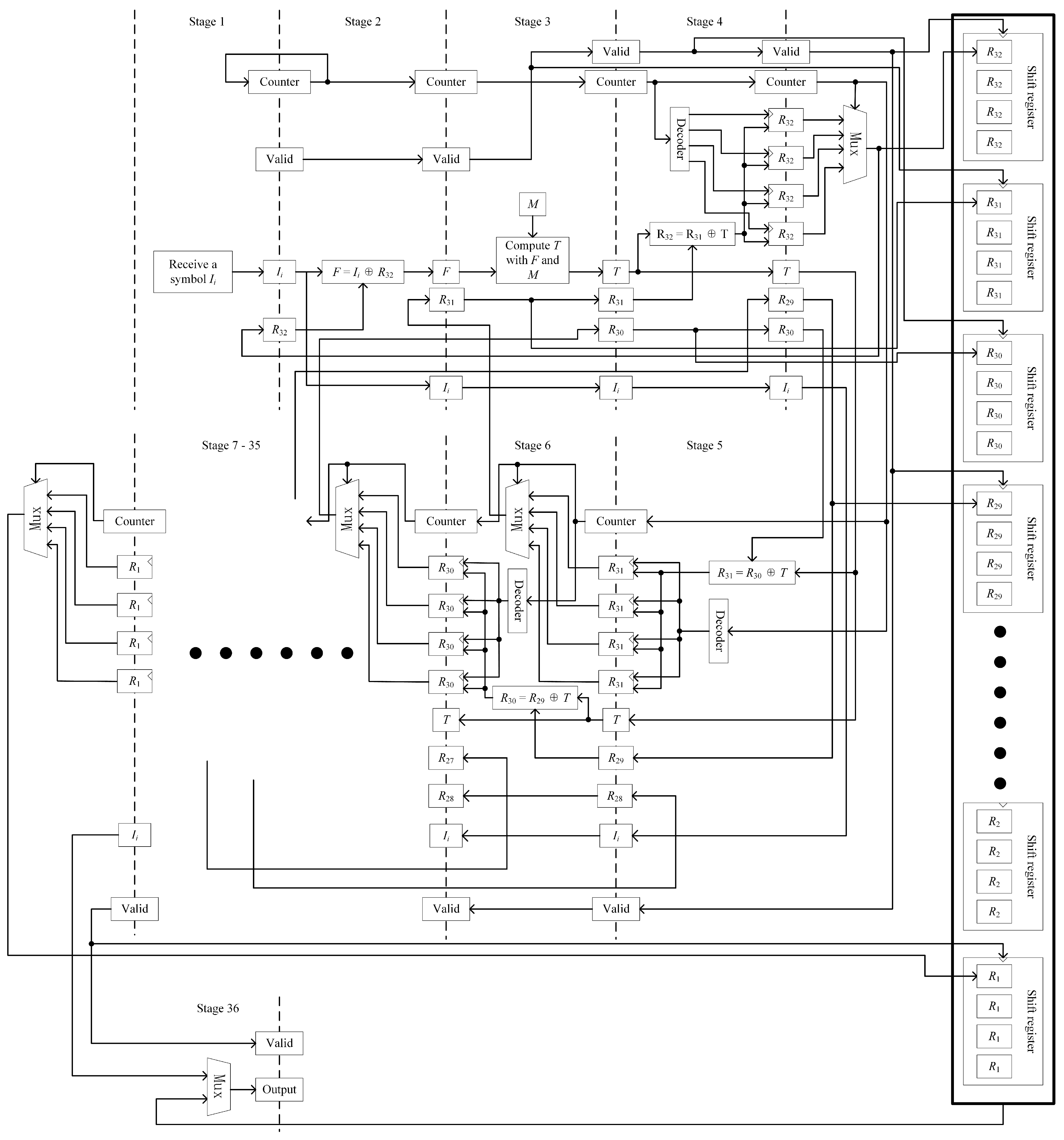
As shown in
Figure 3, the interleaved pipelined architecture is proposed. Each segment between two dashed lines in
Figure 3 is used to represent a single pipeline stage, with the stage number indicated between the lines. The logic of pipeline stages 1 through 6 and stage 36 is illustrated in detail. The stages from 7 to 35 are implemented by replicating the logic of stage 6 and are represented by ellipses for brevity. This architecture is composed of 36 pipeline stages. In the first stage, the input symbol
is received. After each symbol is received, a 2-bit counter, which is initialized to zero, is incremented. This counter is used to indicate which of the four error-correcting sequences—
,
,
, or
—the symbol
belongs to. A 1-bit valid signal is also used. It is initialized to 0 and is set high when a valid symbol is received. Both the valid and counter signals are passed along the pipeline together with the input symbol. At each pipeline stage, the valid signal is checked to determine whether the stage should be activated. Specifically, the registers located along the dashed lines are designated as inter-stage registers, which are used to control the operation of the pipeline. Each stage’s inter-stage register is enabled for writing by the output of the valid register from the preceding stage. When a valid symbol is received, the valid register is set high. This valid signal is successively passed along the pipeline, activating the corresponding inter-stage registers and enabling the pipelined processing of the input data.
The counter is used to determine the interleaved sequence to which the symbol belongs, ensuring that the appropriate inter-stage register group is selected and updated accordingly. Each inter-stage register is composed of four identical sets of parameters, corresponding to the four error-correcting sequences. The counter ensures that data are written to the correct parameter group. An additional register, used for storing the parameter , is included in the first pipeline stage. This register is updated by the fourth stage and is used in subsequent computations.
In the second stage, parameter F is calculated by performing a bitwise XOR between and . In this stage, the parameter is supplied from stage 4 and is bypassed through intermediate pipeline stages to reach the current stage. In addition to being used in the computation, is also written into the inter-stage register of the subsequent pipeline stage for further propagation.
In the third stage, parameter
T is computed according to Equation (
9). Within this stage, the parameter matrix
M, which stores a set of constants, is utilized. The parameter
is bypassed through this stage and forwarded to the next pipeline stage. Beginning from the third stage, the valid signal is not only used as the write-enable signal for the inter-stage registers but is also employed as both the shift and write-enable control signal for the shift registers.
From stage 4 to stage 35, the parameters R are updated sequentially, with one parameter updated per stage in reverse index order. This staged distribution is intentionally designed to facilitate a narrow and elongated physical layout during hardware placement and routing. By structuring the pipeline in this way, several advantages are realized. First, the routing complexity is significantly reduced. Since each stage handles a smaller, isolated portion of the logic, shorter and more localized signal paths can be achieved. This minimizes the need for long interconnects across wide areas of the chip, which often lead to increased delays and timing violations in dense designs. Second, the narrow geometry allows for easier replication of the encoder module in systems requiring parallel processing. When multiple encoder instances are placed side by side, the elongated structure ensures that horizontal wiring between shared control signals, inputs, and outputs remains manageable. As a result, the design is better suited for high-throughput applications that require wide-bit or multi-channel parallelism.
From stage 4 to stage 35, the parameters ( to 32) in the parameter matrix R are updated sequentially, with one parameter updated at each stage. Identical logic is applied across all stages. Initially, all parameters in matrix R are set to zero. In each stage, the updated value of is computed by performing a bitwise XOR operation between T and . Following each update, a 2-to-4 decoder is employed to generate four write-enable signals based on the value of a 2-bit counter. The 2-bit input signal is translated into a 4-bit one-hot output, in which exactly one bit is high, while the others remain low. This one-hot encoding feature enables the 2-bit counter to control four register write-enable signals. Each state of the counter activates the corresponding register, allowing the computed result to be stored separately for the four interleaved error-correcting sequences. The appropriate parameter register is selected based on the current counter value, and the updated result is written accordingly. This mechanism ensures that the results for all four sequences are correctly maintained in parallel throughout the pipeline.
In stage 5, once has been updated, a 4-to-1 multiplexer (Mux) is employed to select one of the four outputs corresponding to the four interleaved error-correcting sequences. This multiplexer receives four candidate values as inputs, each representing the most recent result of from one of the sequences. The selection signal is provided by the 2-bit counter, which determines the currently active sequence. Based on the counter value, one of the four inputs is routed through the multiplexer to the output. The selected value is then fed back to stage 1, where it is used in the encoding of the next input symbol that belongs to the same error-correcting sequence. At the same time, the selected value is written into a shift register specifically associated with . After each write operation, the shift register is shifted by one symbol width to accommodate the next value. Once 892 shifts have been performed—corresponding to the total number of input symbols—the final computed values for all four sequences are retained within the shift register, completing the encoding process.
A similar procedure is followed for the remaining parameters through . After each parameter is updated in stage n, the value is written into the designated register using the decoder. In stage , the value is passed through a Mux and routed to stage , where it is used for the next symbol encoding. In stage , the value is written into its corresponding shift register. In stage 36, the final parameter is selected via a Mux and written directly into its shift register. As long as the number of processed symbols does not exceed 892, the input symbols are output directly. Once all 892 symbols have been output, the contents of the 32 shift registers, comprising 128 parameters, are sequentially output. The 32 shift registers are interconnected as a unified structure. During the parameter update phase, shift operations are performed independently within each register. However, during the output phase, all shift registers are treated as a single logical unit. A unified shift is performed across all registers, shifting by one symbol width per clock cycle. This ensures that all encoded parameters are output sequentially and in the correct order.
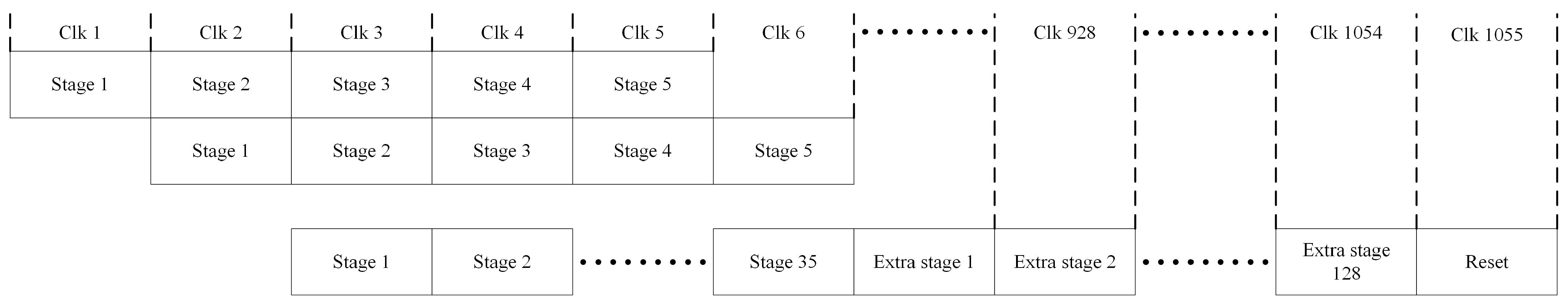
Figure 4 illustrates the operational timing of the pipeline. During the first 892 clock cycles, one symbol is input at each cycle. A total of 892 symbols are processed, corresponding to four interleaved error-correcting sequences, with 223 symbols assigned to each sequence. Each input symbol is propagated through the pipeline and is output 35 clock cycles after it is received.
Once the final input symbol has exited the pipeline, 128 parity symbols are output sequentially. The “extra stage” shown in the figure refers to the stages responsible for outputting these parity symbols, which are generated from the shift operations performed by the 32 shift registers included in the architecture.
Following the completion of parity output, a one-cycle reset is performed to return all pipeline registers to their initial states, preparing the system for the next encoding operation. Including this reset cycle, the total number of clock cycles required to complete the encoding of one full data group 892 symbols is 1055.
Assuming an 8-bit symbol width and an operating frequency of 450 MHz, the theoretical throughput can be calculated as
This value reflects the maximum effective throughput of the pipeline, taking into account the one-cycle reset. In practice, the reset operation requires four clock cycles to complete. In the first cycle, stage 1 to stage 5 and the shift registers from to are reset. In the second cycle, stage 6 to stage 16 and the shift registers from to are reset. In the third cycle, stage 17 to stage 25 and the shift registers from to are reset. Finally, in the fourth cycle, stage 26 to stage 36 and the shift registers from to are reset. Although the reset process spans four clock cycles, only the first cycle impacts the pipeline data processing. As soon as the first reset cycle is completed, the pipeline is ready to receive new data. Therefore, only one clock cycle is effectively counted toward the reset in the throughput calculation.
5. Conclusions
The interleaved pipelined architecture proposed in this study is designed to effectively address the challenges associated with deploying the RS(255,223) encoder. The serial implementation of RS(255,223) has been constrained by its inherent algorithmic structure, which limits the depth of pipelining that can be achieved. These issues are mainly caused by long dependency chains between computation parameters. Parallel implementations, on the other hand, have been hindered by resource inefficiencies.
To overcome these constraints, an interleaving technique was incorporated into the pipelined structure. By enabling the encoder to alternate among four parity codewords, a four-cycle latency window was created for parameters with interdependencies. Consequently, a 36-stage pipeline was implemented. Through this design, a substantial increase in throughput was achieved, allowing performance levels that typically require extensive parallelism to be reached with significantly reduced parallel scaling. Additionally, the introduction of interleaving was found to inherently enhance the system’s radiation tolerance.
The proposed architecture was thoroughly evaluated on the Xilinx XC7K325T platform, with specific attention given to throughput and error correction capabilities. It was analytically and experimentally verified that the system was capable of correcting all classified error types, demonstrating its effectiveness in recovering from both SBUs and MBUs. The results confirmed that high data rates can be supported while maintaining strong error correction performance. Although the achieved throughput was found to be slightly lower than that of the most advanced existing solution, a significantly higher level of radiation tolerance was demonstrated. As such, the proposed architecture is considered well suited for future deployment in space exploration missions where both high throughput and robust radiation resistance are critical.
The design was validated through extensive error injection experiments, which confirmed its resilience against a variety of bit flip patterns. However, it should be acknowledged that the radiation resilience was evaluated using fault injection, which serves as an indirect method of validation. Real-space or radiation chamber testing was not conducted in this study. As such, future work will include physical radiation testing to further substantiate the fault-tolerant capabilities of the proposed architecture under actual space or radiation-rich conditions. This step is expected to enhance the credibility and applicability of the design for space-grade and safety-critical systems.
While the current evaluation was conducted on a single module, potential scalability in system-level integration scenarios has also been taken into account. Due to its modular and pipelined structure, the proposed architecture is considered inherently suitable for deployment in multi-core encoder systems. Under high-traffic conditions, multiple encoder instances may be instantiated and operated in parallel, with efficiency maintained through appropriate scheduling and load-balancing mechanisms. Nonetheless, scalability challenges, such as interconnect bottlenecks and shared resource contention, may be encountered and will need to be carefully addressed in future multi-core system implementations. In future work, these multi-encoder configurations will be explored in greater depth, with the goal of optimizing the encoder performance in large-scale, high-throughput applications.


