Abstract
Intelligent operation and maintenance of urban rail transit systems is essential for improving train safety and efficiency. This study focuses on reducing time, physical effort, and safety risks in deploying intelligent metro inspection robots. This study introduces a design approach for an undercarriage robot simulation system and an offline teaching method. Gazebo and Isaac Sim are combined in this study. Gazebo is used for lightweight simulation in model development and algorithm testing. Isaac Sim is used for high-fidelity rendering and robust simulation in complex large-scale scenarios. This combined approach addresses critical aspects of system development. The research proposes environment data collection and processing methods for metro inspection scenarios. It also provides solutions for hole problems in point cloud mesh models and approaches for robot modeling and sensor configuration. Additionally, it involves developing a target vector labeling platform. Using these elements, an offline teaching system for undercarriage inspection robots has been designed with simulation tools. Offline teaching is unrestricted by on-site space and time. It reduces physical demands and boosts robot teaching efficiency. Experimental results indicate that it takes about 30 s to program a single manipulator motion offline. In contrast, manual on-site teaching takes about 5 min. This represents a significant efficiency improvement. While offline teaching results have some errors, high success rates can still be achieved through error correction. Despite challenges in modeling accuracy and sensor data precision, the simulation system and offline teaching approach decrease metro vehicle operation risks and enhance robot deployment efficiency. They offer a novel solution for intelligent rail transit operation and maintenance. Future research will focus on high-quality environmental point cloud data collection and processing, high-precision model development, and enhancing and expanding simulation system functionality.
1. Introduction
Urban rail transit is a key part of modern urban transport systems and has seen remarkable global progress [1]. As urbanization speeds up and urban populations swell, urban transportation systems face mounting pressure [2,3]. Urban rail transit is vital for enhancing urban mobility and overall livability. Its efficiency and reliability reduce commuting times and boost travel productivity. They also help ease traffic jams and enhance the urban transportation environment [4]. These advantages make urban rail transit a core strategy for solving urban traffic problems. Its high operational efficiency, environmental sustainability, and safety drive this strategic positioning.
To ensure operational reliability and safety, scheduled and unscheduled inspections are essential for metro maintenance [5,6]. Currently, these inspections mainly depend on manual, periodic procedures carried out by trained maintenance staff. Manual inspections involve evaluating key systems like traction mechanisms, braking units, door operations, bogies, and pantographs. Auxiliary subsystems such as air conditioning, signaling, and power supply units are also checked. Among these, undercarriage inspection is crucial and focuses on detecting issues like missing or loose fasteners, unsecured cable connectors, compromised coupler integrity, and fluid leakage beyond safety limits. Inspections usually start around 3:00 a.m. after daily operations end. Technicians work in confined maintenance pits under metro cars, using handheld flashlights and visual inspections to assess components. A standard six-car metro requires verifying over 10,000 checkpoints per inspection cycle. However, traditional manual inspection methods have significant safety risks and operational inefficiencies. Technicians often work in confined, high-pressure environments. Inspection results can vary due to expertise, fatigue, and cognitive workload differences. Under such conditions, ensuring comprehensive and consistent assessments is challenging and increases the risk of undetected faults, which could affect metro operation safety. More importantly, fault detection and maintenance still heavily rely on traditional manual procedures and paper records, which lack effective integration with intelligent maintenance platforms. As a result, the digitization level is low. This restricts real-time condition monitoring and predictive data analytics, hindering the development of intelligent asset management systems.
Under the impetus of Industry 4.0 [7,8], the rail transit sector is experiencing transformative changes driven by digitalization, automation, and cyber–physical integration [9]. In response, this study presents the development of an intelligent robotic inspection system for metros. The system leverages recent advancements in precision navigation, robotic actuation, and high-resolution image analysis. It enables autonomous inspection and continuous monitoring of critical undercarriage and bogie components. It also incorporates real-time anomaly detection and precise fault alerting. Integrated with dynamic image acquisition modules, the platform supports comprehensive inspection coverage, multimodal data fusion, and centralized management of inspection processes [10]. Key features include intelligent visualization dashboards, automated alarm verification, report generation, and dispatching of maintenance work orders. Furthermore, the system offers real-time condition monitoring of key structural zones such as bogies, undercarriages, side panels, and rooftops. This facilitates early fault detection and predictive risk mitigation.
Despite recent advancements, several challenges persist in the practical deployment of intelligent inspection systems. Automated inspection workflows still depend on manual programming of manipulator trajectories, a prerequisite known as the teaching process. This procedure requires predefined navigation waypoints within inspection pits. At each waypoint, technicians manually guide robotic manipulators to align visual sensors with target components. Then, precise joint configurations corresponding to inspection poses are recorded. This time-intensive process must be completed during constrained maintenance windows, typically between 22:00 and 03:00. Moreover, rail depots routinely service a variety of metro models with heterogeneous chassis structures. Even within the same model type, manufacturing tolerances and assembly deviations can lead to positional inconsistencies in critical undercarriage components such as valves and bolts. As a result, individualized teaching sessions are often required for each metro configuration. This substantially increases operational complexity and maintenance workload.
Since being introduced in industrial robotics, simulation technology has evolved from a sole path-planning tool into a comprehensive solution integrating digital twins, augmented reality, and artificial intelligence [11,12], marking a significant milestone in the shift from Industry 4.0 to Industry 5.0 [13,14]. According to the 2022 statistics from the International Federation of Robotics (IFR), over 68% of global automotive manufacturers have deployed simulation platforms based on virtual debugging [15]. An increasing number of enterprises are now establishing these platforms to validate and optimize operational workflows, thereby enhancing production line performance. For example, real-time mapping of physical robots to virtual models enables lifecycle optimization, from initial calibration to complex assembly tasks [16]. Robot simulation has made great progress in algorithm testing, control system verification, and virtual scheduling platforms. Open-source simulation platforms like Gazebo, Webots, CoppeliaSim, and Isaac Sim are widely used in various robot tasks. They help deploy complex operations and iterate optimizations in virtual environments [17,18]. Also, combining simulation with digital twin technology greatly supports the transfer of machine-learning models. This enhances the reality and generalizability of simulation systems [19,20]. Several systematic reviews indicate that research is moving from single-task simulation to system-level, multi-robot collaborative simulation. At the same time, the focus is on modeling abilities for multi-physics and multi-sensor integration environments [21].
Recent advances combining GPU-accelerated physics engines with reinforcement learning have further enhanced simulation fidelity [22,23]. Table 1 presents an overview of several commonly used tools for robot simulation. In the development of mobile robots, manipulators, and drones, Gazebo and Webots stand out as pivotal simulation tools. Gazebo, with its open-source nature and robust support for physics engines, is widely used in robot research and development. It can simulate various sensors and robot types, making it suitable for complex-environment simulation. It also boasts an active community and abundant resources [24,25]. Webots, known for its user-friendly graphical interface and strong support for standards, is widely adopted in the field. Its physics engine is optimized compared to Gazebo, and it has more efficient code editors and debugging tools. However, its integration with ROS is not as deep as Gazebo’s [26,27]. V-REP, a commonly used simulation tool, comes with rich robot and scenario libraries, which gives it an edge in robot modeling and scenario building. It can run on both Windows and Linux systems and is often used for industrial robot simulation. Yet, compared to Gazebo, its integration with ROS is relatively poor. Although it can interact with ROS via plug-in development, it falls short of Gazebo and Webots in ease of use and real-time performance [28,29]. In addition, there are robot simulators built on Unity. While Unity excels in rendering, its engine is relatively large and demands high computer performance. Moreover, its physics engine is not specialized for robot simulation, so it has shortcomings in sensor simulation effects and accuracy [30,31]. In 2024, Nvidia launched Isaac Sim, a simulator featuring high-fidelity physics simulation and rendering, multi-sensor support, high simulation efficiency, rich development tools and resources, and strong AI integration capabilities. It has broad application prospects in industrial automation and other fields. It can be used to train and test robot algorithms and collaborative abilities in complex environments, thereby enhancing robot performance and reliability in real-world applications. These advances provide critical technical support for research on robot offline teaching in the rail transit sector. By developing advanced simulation and digital twin systems that facilitate offline robot programming, the intelligent maintenance capabilities of rail vehicles can be substantially enhanced.

Table 1.
Comparison of robot simulation tools.
In recent years, simulation and digital twin technologies have demonstrated significant advancements in intelligent maintenance for rail transit systems. Their capabilities in multi-source data fusion, real-time feedback, and high-fidelity modeling have proven invaluable for train operational state perception, fault prediction, and maintenance optimization. Li et al. proposed a digital twin-based dynamic compensation framework for mobile inspection robots to enhance perception accuracy and control precision. However, due to the absence of real-time vibration feedback mechanisms, this approach suffers from pose compensation failures under dynamic disturbances such as rail irregularities and curve centrifugal forces [32]. Wang et al. developed an integrated digital twin inspection system supporting path planning and behavioral simulation [33]. Within maintenance operations, these technologies have further demonstrated critical utility. For system-level modeling, the cloud-based CTTSIM architecture achieved real-time rigid–flexible coupled dynamics simulation for six-car trainsets. Through multi-scale model order reduction (MOR), it compressed bogie models with hundred-million-element meshes to computationally tractable scales while preserving micron-level strain field characteristics at critical interfaces, establishing a high-precision platform for predictive maintenance. Nevertheless, by focusing exclusively on mechanical structures, it fails to incorporate essential physical factors such as power supply fluctuations and catenary disturbances [34]. In multi-physics real-time simulations, a traction converter digital twin platform innovatively integrated IGBT thermal management models with multi-timescale data interfaces, achieving junction temperature simulation accuracy exceeding 98%. This resolved parallel chip loss distribution challenges and significantly optimized thermal management efficiency. Yet its confinement to single-device analysis precludes extension to car-level thermo-mechanical coupling effects [35]. Concurrently, a virtual reality-enhanced hierarchical coupler force multi-particle dynamics model enabled visual monitoring of inter-carriage coupling vibrations. While field validation confirmed its reinforcement of autonomous driving algorithms, the model’s neglect of parameter time-variance induced by wheel wear leads to significant error accumulation during long-term operations [36]. In summary, current simulation and digital twin systems face fundamental challenges of insufficient fidelity in physical simulation engines and deficient dynamic adaptability in modeling parameters. These limitations necessitate urgently developing new simulation paradigms tailored for rail transit’s complex and variable operational environments.
As urbanization speeds up and city populations grow, urban transport faces increasing pressure in the rail transit field. Rail transit plays a key role in improving urban residents’ quality of life [37]. To boost the operation and maintenance efficiency and response capability of rail systems, digital twin and simulation technologies have been gradually introduced into key areas such as train control systems, vehicle scheduling, energy consumption management, and track condition prediction. In addition, research has explored virtual train composition, traffic simulation, and safety control strategies under a vehicle-to-infrastructure collaboration framework [38,39,40,41]. These achievements have not only promoted the intelligent development of rail transit but also offered a technological foundation and simulation experimental platform support for urban smart mobility. In view of the complexity of undercarriage inspection robot systems and the vast amounts of data (including laser point clouds, depth images, and video streams, among others) generated during their operation, this research will first develop a fundamental simulation tool based on Gazebo, which is deeply integrated with ROS, with the goal of exploring design methods for undercarriage inspection robot simulation systems. Subsequently, building on this foundation, the research will further investigate the development of more advanced simulation tools using Isaac Sim.
Offline programming is a key method for enhancing robot efficiency and reducing costs, with broad industrial applications such as debugging automated production lines, developing robot welding systems [42], ensuring coating quality of complex parts with thermal spray robots [43], and ABB’s specialized offline programming software for improving collision detection and operational debugging efficiency [44]. However, offline programming faces three primary challenges. First, developing high-precision models is time-consuming, while simplified models reduce teaching accuracy due to scene discrepancies. Second, limited sensor integration and data latency constrain robotic perception capabilities. Third, specialized software/hardware requirements (e.g., high-performance computers) increase costs and limit applicability. The rail transit industry demands stringent personnel and equipment safety. Manual inspections are laborious and risky, so developing an offline teaching solution for this industry is highly significant. It can resolve existing challenges and boost the industry’s intelligence level. Unlike offline programming, which focuses on automated robot program generation and optimization, the proposed offline teaching method emphasizes using simulation system development to design robot navigation points and manipulator motions through human–machine interaction.
This study aims to develop an efficient metro train undercarriage inspection robot simulation system and offline teaching solution. To fulfill this objective, a lightweight Gazebo simulation system and a high-fidelity Isaac Sim simulation system have been developed. Each has unique advantages that can satisfy the diverse requirements of metro undercarriage inspection tasks. The research design encompasses several key steps. First, laser scanning technology is utilized to reconstruct the metro undercarriage inspection scenario. Second, environment and robot models are established. Additionally, a vector-based inspection target labeling platform is created. This platform enables precise vectorization marking of inspection targets within the models. Finally, a structured offline teaching method is designed. This method includes navigation point setup, manipulator operation, and automatic data recording.
The significance of this research is reflected in the following aspects. First, from a theoretical perspective, this study conducts an in-depth exploration of simulation and offline teaching methods for undercarriage inspection robots in rail transit. It systematically introduces, for the first time, methods for high-precision vehicle chassis modeling, the construction of information annotation platforms, the design of simulation scenarios, and corresponding robot modeling techniques. This effectively fills gaps in the existing literature, enhances the theoretical framework, and provides a solid foundation and new directions for future research. Second, from a practical standpoint, the proposed offline teaching scheme for undercarriage inspection robots significantly improves teaching efficiency, reduces operator workload, and minimizes human-induced errors during the teaching process. Furthermore, it enhances the operational accuracy and reliability of inspection robots. It also offers robust technical support for intelligent rail transit maintenance and promotes the industry’s transition toward intelligent and automated development, demonstrating substantial practical value and broad application prospects.
2. Project Background and Challenges Therein
2.1. Introduction to Undercarriage Inspection Tasks
As shown in Figure 1, metro inspections are typically conducted at the vehicle maintenance depot. Maintenance personnel perform daily operational maintenance checks on metros that have been taken out of service. The chassis, as the primary load-bearing structure, directly affects a metro’s operational stability, safety, and ride comfort. Due to frequent starts and stops, high-speed operation, and complex track conditions, metro metros undergo substantial mechanical and environmental stresses on their chassis components. Therefore, systematic and regular inspections are essential to promptly detect potential faults, prevent accidents, and ensure the continuity and reliability of metro operations.
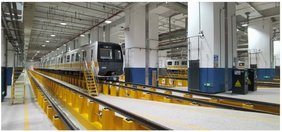
Figure 1.
Metro vehicle depot maintenance base.
As shown in Figure 2, metro undercarriage inspections cover several key components and systems: bogie structural elements, including detection of cracks, deformations, or wear on frames and side frames; wheel treads, involving identification of scratches, spalling, and cracks, measuring flange height and thickness, and verifying wheel-axle assembly integrity; suspension systems, assessing the operational status and fastening conditions of air springs, hydraulic dampers, and rubber stacks; piping, checking for leaks, ruptures, and aging; and the condition of undercarriage cleaning and lubrication.
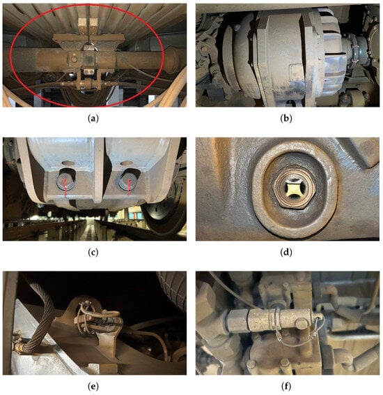
Figure 2.
Metro chassis inspection components: (a) Semi-permanent coupler. (b) Motor. (c) Motor mounting bolts. (d) Oil level gauge. (e) Linchpin. (f) Lead seal.
Manual inspections follow predefined routes and checklists. Inspectors perform visual examinations of the undercarriage and basic functional tests, relying on their experience and professional expertise to assess equipment condition. Figure 3 shows a real-life manual metro inspection. These inspections are typically performed once per day—often at night when vehicles are stationary—allowing for detailed examination without disrupting service. First, the appearance of key components (bogie, wheels, braking system, suspension device, piping, and wiring) is checked for cracks, deformation, loosening, or leakage. Second, the tightness of fasteners is verified to identify any loosened or missing parts. For a six-car metro, a single manual inspection can involve over 10,000 individual checkpoints, most concentrated on the undercarriage. Consequently, inspectors spend extended periods working within a confined, physically demanding inspection trench.
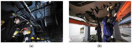
Figure 3.
Manual inspection: (a) Repair the piping. (b) Inspect the braking system.
2.2. Rollingstock Undercarriage Robot
Several variants of rollingstock undercarriage robots have been developed in prior work. This study focuses on a compact version featuring a collaborative manipulator, as shown in Figure 4. The system integrates a wheeled mobile platform, manipulator, and vision module, operating within railway inspection pits to autonomously inspect undercarriage components and side panels. This robotic innovation addresses key limitations of manual inspection, such as harsh working environments, high physical demands, and human judgment variability, thereby reducing maintenance personnel workload, improving inspection quality, and systematically mitigating operational safety risks.
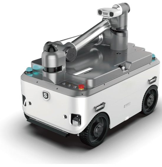
Figure 4.
Rollingstock undercarriage robot.
The robot’s technical parameters are presented in Table 2. Its chassis is equipped with eight drive units, enabling omnidirectional mobility for enhanced maneuverability in complex environments. Three LiDARs, mounted at the front, rear, and top, provide comprehensive environmental perception, facilitating accurate obstacle avoidance and navigation.
Table 2.
Technical parameters of the robot.
The robot incorporates multiple safety features, including an emergency stop mechanism, front and rear collision avoidance systems, and a virtual wall for the manipulator. It carries a six-axis collaborative manipulator equipped with a multifunctional inspection device. By integrating feature matching, deep learning algorithms, and edge computing, the robot enables efficient and comprehensive fault detection of the metro undercarriage. This multi-technology solution significantly enhances detection performance and provides robust technical support for intelligent metro maintenance.
To support the development of this robot, an undercarriage inspection scenario was independently constructed, as shown in Figure 5. The scenario incorporates an actual metro vehicle and precisely replicates the depot pit environment, faithfully simulating real-world maintenance conditions. As a result, this highly realistic development environment significantly enhances development efficiency and ensures that the robot can undergo comprehensive performance testing and optimization prior to field deployment.
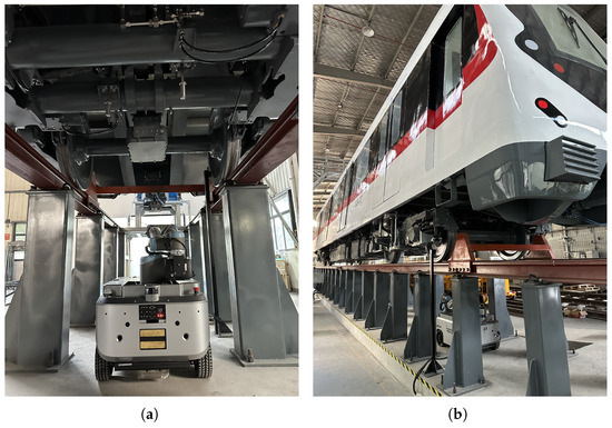
Figure 5.
The inspection of the metro undercarriage is divided into two parts: (a) Inspection under the metro undercarriage. (b) Inspection along the side of the metro undercarriage.
The robot was deployed for long-term operational testing at a metro vehicle depot, as shown in Figure 6. The deployment procedure is outlined as follows. First, the robot’s LiDAR system was used to scan the environment and generate a 2D grid map of the entire depot. Based on maintenance requirements, inspection points and the location of the automatic charging station were marked on the map. Subsequently, the robot’s route was manually planned according to actual working conditions. Once the navigation points were configured, the robot was remotely operated to perform offline teaching of manipulator actions both in the undercarriage pit and alongside the vehicles. It is worth noting that the teaching process is the most time-consuming and labor-intensive stage of the robot deployment, significantly limiting the initial deployment efficiency. This remains a bottleneck due to the lack of more efficient solutions in current industry practices.
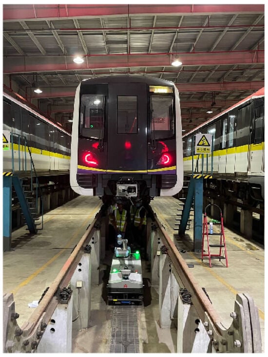
Figure 6.
The robot performs tasks at the vehicle depot.
2.3. Challenges and Solutions
In practical applications, rollingstock undercarriage robots face several challenges during metro inspections. First, the detection of component defects relies heavily on both 2D and 3D perception algorithms. Since the inspection image data must be acquired through manipulator control, modifying the manipulator’s trajectories and adjusting camera focus settings and zoom levels on-site is time-consuming and labor-intensive. Consequently, collecting image samples from multiple angles, under various lighting conditions, and with different focal settings becomes highly inefficient. This limits the diversity and coverage of training data for large-scale fault detection models, ultimately reducing algorithmic accuracy. An improved data acquisition strategy would substantially enhance model performance. Second, a full metro comprises tens of thousands of inspection points, all of which require manual teaching through robot and manipulator operation. This process demands extensive time and effort and must typically be conducted during early morning hours after metro service ends, causing significant physical and mental strain on maintenance personnel. These limitations collectively highlight the need for improved robot inspection workflows, particularly in enhancing data acquisition efficiency and optimizing the teaching process. An in-depth analysis of the existing metro inspection tasks and robot systems has revealed a significant efficiency bottleneck in the current robot deployment process. This is particularly evident in the manipulator teaching phase. Hence, it is necessary to design a new offline teaching solution. The aim is to optimize this process through simulation technology. This study proposes a design approach where a simulation system is used to pre-program and test robot navigation points as well as manipulator motions. Then, the pre-set point information is deployed onto the robot for on-site verification and fine-tuning. This helps reduce the time and resources required for on-site teaching.
In the field of metro vehicle undercarriage inspection, despite the clear advantages of robotic systems, their development remains constrained by challenges in data acquisition and labor-intensive teaching procedures. To address these limitations, this paper proposes an innovative simulation-based solution that integrates an undercarriage robot simulation system with an offline teaching framework. This approach aims to improve inspection efficiency and quality while providing a solid theoretical and practical foundation for the digital transformation of the industry.
Digital twin technology has emerged as a prominent research focus in industrial robotics [11,45]. The proposed simulation system represents a foundational step toward building a digital twin for metro maintenance and inspection. It enables accurate simulation of inspection scenarios, offering a flexible and efficient platform for algorithm testing and optimization, thereby significantly reducing the need for on-site data collection. Leveraging the simulation environment, diverse image samples can be rapidly generated under varying perspectives, lighting conditions, focal settings, and distances, enhancing the comprehensiveness of training datasets and improving the accuracy of fault detection models.
Furthermore, the offline teaching solution supports the pre-planning and optimization of manipulator trajectories within the virtual environment. These optimized motions can be directly transferred to real-world applications, substantially reducing the time and human effort required for on-site teaching and enhancing deployment efficiency. Overall, this solution lays a robust foundation for the future development of a digital twin-based intelligent maintenance framework, accelerating the industry’s transition toward smart and automated operations.
3. Gazebo-Based Simulation System Development
Given the complex and large-scale inspection environment, the metro train undercarriage inspection robot simulation system must handle. And considering the challenges of large-scale, high-precision scene modeling in simulation fields. The robot model integrates complex structures and devices like manipulators, cameras, LiDAR, and mobile chassis. This chapter aims to rapidly design and develop a simulation system. Its core objective is to explore the development path of simulation systems for metro train undercarriage inspection. Also, to verify the potential effectiveness of the undercarriage inspection robot simulation system in solving real-world problems. Based on this, this study selects Gazebo as the simulation platform. Gazebo is chosen for its high integration with ROS and relatively low development difficulty. Then, the study investigates the design and development solutions of the simulation system.
Gazebo is an open-source simulation platform widely adopted in robotics research and development [46,47,48,49]. It plays a significant role in advancing robotic technologies by offering a comprehensive set of features. With support for multiple physics engines, Gazebo enables realistic simulation of physical interactions, including motion, collisions, and contact dynamics. It also emulates a wide range of sensors, including LiDAR, RGB cameras, and depth cameras, thereby creating a virtual testing environment with high fidelity to real-world conditions.
In addition, Gazebo allows the construction of complex environments tailored to specific task requirements, whether in open terrains or confined spaces with dense obstacles. Its high scalability further enables the integration of custom plugins, allowing researchers to extend system functionality to meet the evolving needs of robotic applications.
Gazebo holds paramount importance in robotics development, as it enables the programming, debugging, and optimization of robotic systems within a virtual environment, thereby eliminating reliance on expensive and potentially hazardous hardware platforms. This capability not only reduces development costs but also mitigates numerous operational risks. Through iterative testing and refinement of control, perception, and navigation subsystems in simulation, developers can validate high levels of performance prior to physical deployment.
Furthermore, Gazebo supports the emulation of complex multi-robot scenarios, which is essential for investigating collaborative behaviors and enhancing overall system efficiency. As robotic technologies continue to advance, Gazebo is expected to remain a foundational tool for simulation, providing robust support for innovation and practical application.
This chapter introduces the architecture of an intelligent undercarriage inspection robot simulation system. By integrating key technologies, multi-source perception data fusion, point cloud-based reverse-engineered modeling, and intelligent path planning, a Gazebo-based undercarriage robot simulation platform is established. The platform comprises the following core modules:
- (1)
- Laser Point Cloud Acquisition Module performs comprehensive scanning of rail vehicle undercarriages and inspection pits using both stationary and handheld laser scanners. By evaluating data quality across devices and scan positions, it defines an optimized point cloud acquisition scheme for rail scenarios.
- (2)
- Point Cloud Data Processing Module preprocesses raw scans through alignment, merging, and clipping to produce continuous, high-fidelity point cloud datasets suitable for simulation and modeling.
- (3)
- Reverse-Engineered Modeling Module converts processed point clouds into mesh models. This rapid reconstruction approach overcomes Gazebo’s limitation of importing raw point clouds and enables seamless integration of undercarriage geometry into the simulation environment.
- (4)
- Intelligent Inspection Target Vectorization Module provides a dedicated annotation tool for marking inspection points directly on point cloud data. The exported coordinates are meshed into inspection point models, which are then imported together with the undercarriage mesh into Gazebo for visualized target definition.
- (5)
- Robot Model Design Module generates a 3D robot representation in SolidWorks 2020, configures sensors, controllers, and joints, and exports the assembly in URDF format. Sensor parameters, manipulator controllers, and chassis dynamics are subsequently configured within ROS and Gazebo.
- (6)
- Safe Motion Planning Module converts undercarriage point clouds into a 3D voxel representation and leverages ROS MoveIt to plan collision-free manipulator trajectories, ensuring the safe execution of inspection tasks in confined pit environments.
The Gazebo simulation system designed in this study has six core modules. The laser point cloud acquisition module acquires high-quality environmental data. The point cloud data processing module preprocesses the data to ensure modeling accuracy. The reverse-engineered modeling module converts the processed data into an environmental model for simulation. The intelligent inspection target vectorization module enables the manual precise marking of inspection targets. This helps the robot adjust the manipulator posture accurately to capture the targets. The robot model design module and the safe motion module work together to ensure safe robot motion and efficient task execution in the simulation. It should be noted that in the system design, this study has taken relevant measures to minimize the impact of possible errors on the simulation results during the design phase. However, simulation results cannot fully reflect real-world operations, as errors cannot be completely eliminated. Therefore, when deploying simulation results to real robots, it is necessary to first verify and fine-tune the simulation results to ensure their effectiveness and reliability in real environments.
3.1. Laser Point Cloud Acquisition Module
This study conducts an in-depth comparison of four laser-based modeling devices: Leica RTC360 stationary 3D laser scanner, Leica RLP6 handheld 3D laser scanner, Trimble X7 stationary 3D laser scanner, and Z+F 5016 3D laser scanner (Figure 7). Point cloud data were collected across the chassis and underfloor conduits of a metro vehicle at a self-built inspection site. Because certain chassis regions were obstructed by onboard equipment, each scanner had to be positioned at specific locations and adjusted to appropriate heights to capture all internal details fully.
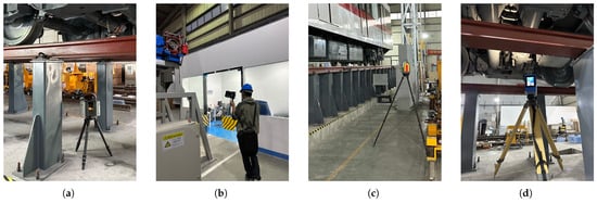
Figure 7.
3D laser scanner: (a) Leica RTC360. (b) Leica RLP 6. (c) Trimble X7. (d) Z+F 5016.
3.1.1. Leica RTC360 Scanning Results
The Leica RTC360 features compact size, lightweight design, and high portability. Field experiments indicate that each scanning position requires 86 s, and a total of 20 positions are needed to cover a metro carriage and its underfloor conduits. Including equipment setup and data preprocessing, the complete scanning workflow is completed in approximately 60 min. Selected scan results are presented in Figure 8.
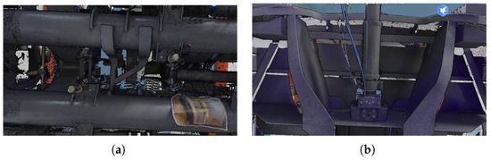
Figure 8.
Leica RTC360 Colored Point Cloud Scan Results: (a) Axle details. (b) Coupler details.
As shown in the point cloud visualization in Figure 8, the Leica scanner’s advanced imaging system simultaneously captures HDR imagery during laser scanning, yielding richly colorized point clouds with high radiometric fidelity and remarkably without the need for auxiliary lighting.
3.1.2. Leica RLP6 Scanning Results
The Leica RLP6 handheld scanner proved to be the most rapid device evaluated. By simply moving the handheld unit around the metro carriage and its underfloor conduits, the operator acquires complete point cloud data in approximately 10 min per vehicle. Nevertheless, due to the absence of an integrated camera, the resulting dataset consists solely of colorless, monochrome point clouds. Sample scanning results are shown in Figure 9.
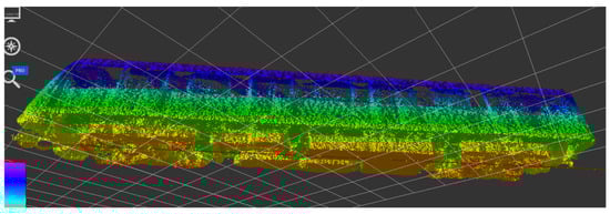
Figure 9.
Leica RLP6 colored point cloud scan results.
Due to the absence of an integrated camera, the Leica RLP6 handheld scanner produces uncolored, sparsely sampled point clouds; consequently, registration inaccuracies and geometric deviations arise in the reconstructed metro carriage model (Figure 9).
3.1.3. Trimble X7 Scanning Results
Under identical conditions, the Trimble X7 stationary scanner acquired point cloud data at 19 scanning positions, requiring approximately 4 min per position (75 min total). Upon completion, both the point cloud dataset and panoramic imagery were immediately accessible via the control terminal (Figure 10).
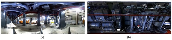
Figure 10.
Trimble X7 colored point cloud scan results: (a) Panorama of the wheel and bogie. (b) 3D point cloud.
Because the Trimble X7 lacks integrated fill-light capability, multiple external flashlights are required to provide adequate illumination of the metro carriage chassis during scanning; otherwise, the resulting point clouds remain too dark to allow precise detection of inspection targets.
3.1.4. Z+F 5016 Scanning Results
The Z+F scanner required 20 stations, with each station taking 4 min, resulting in a total scanning time of 140 min. The extended duration is primarily due to the need for manual leveling of the Z+F device, which reduces overall scanning efficiency. However, the Z+F is equipped with an integrated fill light, allowing it to capture images and point cloud data with ideal brightness, as illustrated in Figure 11.
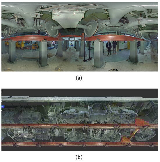
Figure 11.
Z+F 5016 Colored Point Cloud Scan Results: (a) Panorama of the wheel and bogie. (b) 3D point cloud.
3.1.5. Discussion on 3D Scanning Devices
The point cloud data acquired by the stationary scanner satisfies the fundamental criteria for metro carriage undercarriage inspection. The three-dimensional data demonstrates high density and strong performance in both registration accuracy and color fidelity, resulting in clear and detailed visual outputs. Although some devices may lose detail in panoramic images under poor lighting conditions, this limitation can be mitigated by incorporating fill lighting during data acquisition.
Specifically, under proper lighting conditions, panoramic imaging on the side of the metro carriage can clearly reveal fine features such as anti-loosening markings on bolts. This indicates that, under appropriate lighting, the stationary scanner can acquire images with sufficient detail to support part detection via panoramic views during offline teaching. Moreover, experienced operators are able to accurately identify inspection target locations solely based on the point cloud data.
Considering scanning efficiency, cost-effectiveness, and data quality, the Trimble X7 scanner was selected as the most suitable data acquisition device. This choice ensures both efficient and accurate data collection, laying a solid foundation for subsequent simulation system development and inspection tasks. It is important to note that metro trains of different models vary in structure, and even those of the same model may exhibit variations in the positions of equipment and components due to manufacturing tolerances and long-term usage. As a result, the Aurora data acquisition system does not currently offer universality. To address this situation, it is necessary to perform data collection specifically for each metro train requiring robot-assisted inspection.
As illustrated in Figure 12, two Trimble X7 scanners were deployed in a field scenario to complete the data acquisition of six metro carriages and their associated underfloor ducts within four hours. Each scanner was equipped with four fill-light units to ensure the quality of the captured point cloud data.
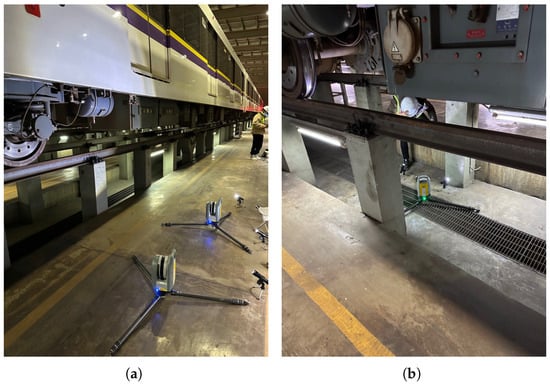
Figure 12.
Vehicle section on-site data scanning: (a) Scanning of the undercarriage side. (b) Scanning of the undercarriage bottom.
After data acquisition, a thorough quality assessment of the acquired 3D data is required to ensure that all relevant undercarriage details have been clearly captured. Representative results are shown in Figure 13, where the point cloud details of both the front section of the metro carriage and its undercarriage are clearly visible. Inspection targets can be identified directly from the point cloud data.
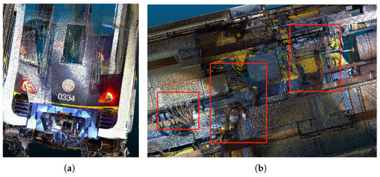
Figure 13.
Point cloud detail presentation: (a) Point cloud of metro head. (b) Point cloud of metro bottom.
3.2. Point Cloud Processing Module
The initial step in processing raw point cloud data is to filter out irrelevant information, retaining only the point cloud data of the metro carriage and the inspection duct. The yaw angle of the point cloud is then adjusted to achieve precise alignment of the metro and duct with the coordinate axes, thereby facilitating the subsequent offline teaching process.
Prior to importing the data into the simulator, the origin of the simulation environment must be defined. In this project, the origin is defined as the ground projection point of the coupler at the front end of the metro carriage to unify the coordinate systems of the robot, inspection environment, and sensors.
Due to potential parking deviations of the metro carriage, the point clouds of the duct and the vehicle are segmented. The robot detects the position of the front section of the carriage to determine the parking deviation, which serves as the basis for the coordinate compensation of subsequent navigation and inspection points. The segmented vehicle undercarriage and duct point cloud data are shown in Figure 14.
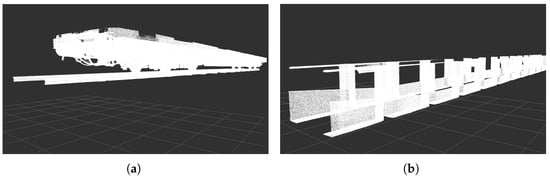
Figure 14.
Point cloud segmentation: (a) Point cloud of metro undercarriage. (b) Point cloud of inspection duct.
The simulation system in this study was run on a computer equipped with an 11th Gen Intel(R) Core(TM) i9-11900KF processor @ 3.50GHz, 128 GB of RAM, and an NVIDIA GeForce RTX 4090 graphics card with 24 GB of dedicated memory. However, when loading point cloud data exceeding 1 GB into Gazebo, significant system latency was observed due to the prolonged computation time required by the controllers. To mitigate this issue, all point cloud data were downsampled using a voxel grid filter with a resolution parameter of 0.015 and subsequently saved in PCD format. As a result, the data size for a single metro carriage was reduced to 42 MB and that of the corresponding ducts to 13 MB. This preprocessing step effectively alleviated performance bottlenecks in the simulation while preserving sufficient detail for inspection and planning purposes.
3.3. Point Cloud Reverse Engineering Modeling Module
To address the challenge of importing point cloud data into Gazebo as a model, this study proposes a solution using point cloud reverse engineering modeling. First, import the point cloud data into Geomagic software, select the highest quality settings during meshing, and output the model in STL format. Since Gazebo does not support direct import of colored models, colors and texture images need to be designed separately and loaded individually.
However, there is an inherent drawback in automatically meshing point clouds into model-format files. The normal vector direction of the generated mesh model’s faces cannot be controlled. This causes many holes in the model when loaded into Gazebo, as shown in Figure 15a. The reason is that Gazebo only displays normal vectors within a fixed range. If the normal vector points inward, the corresponding face will not be displayed correctly.
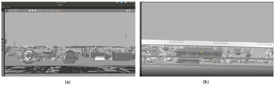
Figure 15.
Point cloud meshing model: (a) The model generated by the meshing algorithm has many holes. (b) The model obtained by double-sided meshing solves the problem of holes.
To resolve the issue of incomplete model visualization in Gazebo caused by inward-facing surface normals, this paper proposes a practical mesh post-processing technique. After generating the mesh model as described previously, a duplicate of the model is created, and the direction of all surface normals in the duplicate is inverted. The original and inverted models are then combined into a single composite mesh. This approach ensures that all surfaces are visible regardless of normal orientation. The result, after importing them into Gazebo, is illustrated in Figure 15b.
As illustrated in Figure 15a,b, the double-meshed model is fully and accurately rendered in Gazebo, with all structural details clearly preserved. This approach effectively addresses the issue of missing surfaces caused by inward-facing normals, thereby ensuring the usability of the imported model. After processing in this way, the model can provide correct results for the LiDAR and camera in the Gazebo simulation without obtaining incorrect data due to model holes. It has been verified that the processed mesh model meets the requirements of the simulation system. The double-grid method improves model display in Gazebo by flipping normal vectors and integrating models. It effectively reduces display holes. It retains the original geometric details. It ensures consistency between the simulation display and real-world scene. This offers accurate environmental data for robot path planning and manipulator operation.
3.4. Intelligent Inspection Target Vectorization Module
Target vectorization is a method used to obtain the coordinates and orientation of inspection targets. In this study, due to the large data volume of metro vehicles and the complexity of inspection areas and components, we have developed a vectorization annotation platform based on a WebGL large-scale point cloud renderer. The platform is capable of directly importing and displaying colored point cloud data collected by the Trimble X7, as shown in Figure 16. As an example, a coupler is annotated by selecting it with a rectangular box tool, where the target’s name, category, and orientation are labeled to complete the annotation.
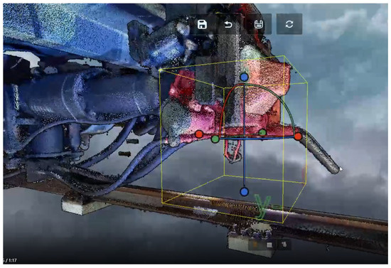
Figure 16.
Target vectorization annotation.
After completing all annotations, the annotated point-location information is exported in a specified format. Then, in ROS, circular yellow models are created for these points and imported into Gazebo for display alongside the undercarriage model.
3.5. Robot Model Design Module
Having completed the robot body design and production in prior work, a detailed 3D model is available in SolidWorks’ STEP format. This richly textured model with precise dimensions enhances localization, navigation, and manipulator simulation in ROS. Nevertheless, its large file size-stemming from complex textures and numerous facets-poses the following challenges in ROS:
- ROS simulators such as Gazebo and RVIZ are unable to load the large model.
- Even if the model is loaded, the simulator experiences significant lag due to limited computer performance, usually dropping to around 10 frames per second, which compromises the visual quality.
- An unconfigured 3D model, lacking the proper configuration of links, joints, and sensor positions, cannot accurately control the manipulator or wheel rotation.
In order to utilize more realistic and high-precision models in ROS simulations, one must first master the basic SolidWorks operations and the procedure for creating URDF models in ROS. First, this paper converts the SolidWorks model file into a URDF model. Subsequently, to configure the two controllers for the vehicle undercarriage and manipulator control, the URDF model is then further converted into an XACRO model.
In this study, the configuration of the robot model followed the steps outlined below: First, key points on the robot were selected for components such as lasers, cameras, manipulators, and wheels, with coordinate systems created for each. Next, the rotation axes of the wheels and manipulators were defined to establish the model’s orientation reference. Then, the robot’s origin was chosen, and the base_link was created, serving as the base coordinate system. Subsequently, links were created for other components (e.g., sensors, wheels), completing the model structure. The configured robot links are illustrated in Figure 17. After the links were created, the parameters of each joint were carefully checked and configured to ensure that their motion ranges and connection methods met the design requirements. Simultaneously, the properties and relationships of all links were checked to verify the model’s integrity and correctness. Upon completion of all settings, the model was saved as a package and exported as a URDF file for subsequent simulation and control in ROS. Although SolidWorks offers the functionality of automatically configuring links and joints, for complex models, this automatic configuration process may lead to errors or inaccuracies. Therefore, to ensure the precision of the model configuration, manual configuration is recommended.
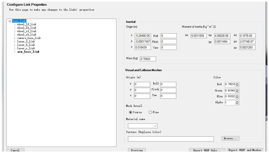
Figure 17.
The links of the robot configured in SolidWorks.
After completing the steps above, the robot’s URDF file is exported for display in Gazebo. Upon completion of the chassis robot URDF modeling, Gazebo’s controller plugins for the wheels and manipulator are configured. This requires converting the URDF model to an XACRO model for subsequent configuration. Since the URDF and XACRO formats are similar, and the controller configuration is straightforward, this process is not elaborated upon here. The camera model mounted at the robotic manipulator end-effector is ZIVID, which captures visible-light images and simultaneously generates high-precision depth maps using a structured light array. These depth maps enable the detection of bolt loosening. ZIVID provides URDF files that can be directly integrated into the robot’s URDF configuration.
When using Solidworks to export a robot URDF file, you can convert it to an XACRO model file by simply modifying the declaration in the model file. Specifically, rename the file extension from .urdf to .xacro at the beginning of the file, and update the declaration to <?xml version="1.0" encoding="UTF-8" ?> and <robot name="robot_name" xmlns:xacro="http://www.ros.org/wiki/xacro">. Next, import the XACRO files of the ZIVID camera and UR10 manipulator into the robot model. Use a fixed-type joint to configure the camera and manipulator on the robot model, as shown in Figure 18a. For instance, use the <include filename="zivid_file_path"> tag to import the ZIVID camera’s XACRO file into the robot model, and use the <joint name="zivid_joint" type="fixed"> tag to mount it on the manipulator’s end-flange tool0. Setting the joint type to fixed ensures a rigid connection between the ZIVID camera and the manipulator’s flange. Also, the robot’s manipulator base is a height-adjustable mechanism. So, a motor is needed to control this mechanism. As shown in Figure 18b, a lifting joint named "trans_joint" is added to the mobile base model of the robot. A drive motor is configured for this joint, thus achieving a vertical movement of 0.4 m.
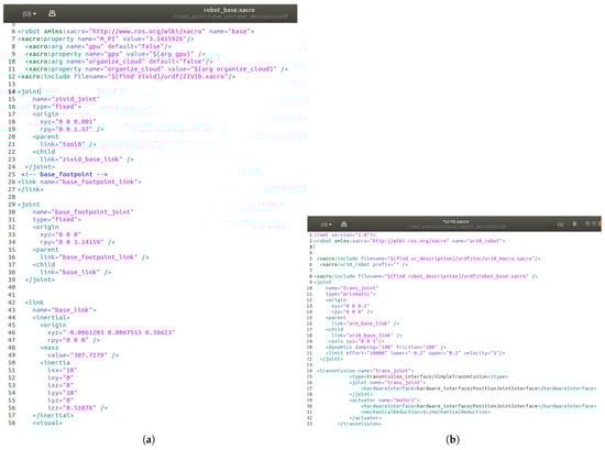
Figure 18.
Robot model URDF description file: (a) Import ZIVID into the robot base model and fix it on the manipulator. (b) Configure a lifting mechanism for the manipulator.
Figure 19 illustrates the robot’s coordinate system framework after configuration. It includes the coordinate systems of the camera, LiDAR, manipulator, wheels, base, and lifting mechanism, showing their positions and hierarchy.
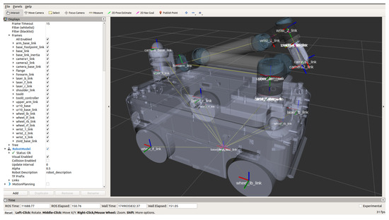
Figure 19.
Overview of the Robot Coordinate System.
After all configurations are completed, the robot model is capable of running localization, navigation, manipulator control, and image detection algorithms in the simulation, as shown in Figure 20.
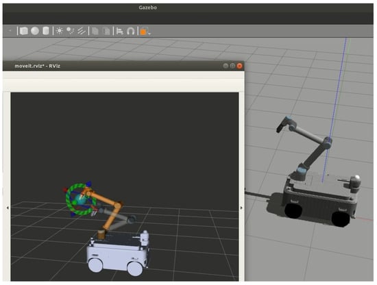
Figure 20.
The robot model imported into Gazebo.
During the conversion of Solidworks models to URDF models, it is necessary to simplify the models. This involves removing internal complex structures and redundant components of the robot, such as screws, batteries, and bearings that do not affect the appearance. If simplification is not carried out, the exported URDF model file will be too large. This will significantly increase the computer performance requirements after importing into the simulator, causing the simulator to run slowly or even fail to start. Therefore, the simplification of Solidworks models is essential. After simplification, the model only retains the size and positional relationships of the robot’s key components. This ensures that the model’s kinematic and dynamic characteristics in the simulation are highly consistent with those of the actual robot.
3.6. Safety Motion Module
Achieving safe and collision-free motion control for manipulators in the narrow spaces of metro inspection pits is crucial. This technology significantly improves inspection efficiency and quality. Precise path planning ensures the autonomous detection of key components by the manipulator, reduces oversight risks in manual inspections, and enhances fault detection accuracy. Simultaneously, this control method reduces maintenance costs, safety risks, and equipment damage from collisions while ensuring stable robot operation. Furthermore, it enhances the flexibility and adaptability of inspections, establishing a technical foundation for future complex inspection tasks and efficient maintenance models.
In the robot URDF modeling, the mobile base, manipulator, and end-mounted camera are included. The URDF also incorporates collision models between the robot body and the manipulator. By loading the URDF file, collision detection between the mobile base and the manipulator can be implemented, thereby avoiding collisions with the mobile base during manipulator motion planning.
This paper discusses a manipulator safety path planning method based on laser point cloud data. Section 3.1 presents a 3D laser data acquisition method specifically tailored for rail transit applications. Using this method, comprehensive and accurate point cloud data of vehicles and inspection pits were obtained. Compared to the real-time laser point cloud data acquired during robot inspections, the pre-collected point cloud data exhibits higher precision and completeness, making it more advantageous for safe manipulator path planning.
In this study, the manipulator acquires environmental data by converting PCD point cloud data into 3D OctoMap format, which represents the environment as voxel grids, with each voxel recording the occupancy probability. This format allows the manipulator controller to perform safe path planning. One limitation of this method is that every time the robot navigates to a new position, the point cloud and 3D Octomap need to be recalculated and reloaded for the manipulator controller. This involves complex computations and typically takes a long time to complete. Thus, selecting a proper resolution to provide precise environmental and structural information and fast loading is key to enhancing robot inspection performance. To address the long Octomap loading time, a local point cloud processing method based on robot position is proposed. Tests on the manipulator controller loading Octomap show that high-resolution Octomap offers more accurate structures and details but takes longer to load due to high computational demands, as seen in Figure 21. Considering the robot and manipulator’s movement range, for safe obstacle avoidance, there is no need to load all subway data at once. Instead, loading Octomap with proper resolution within the robot’s movement range is sufficient.
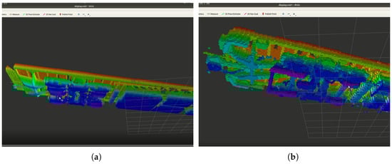
Figure 21.
An Octomap consists of numerous cubes. Below are the display effects of Octomap at different resolutions: (a) The display effect of Octomap with a cube edge length of 1 cm. (b) The display effect of Octomap with a cube edge length of 5 cm.
This paper conducts experiments on data loading for varying lengths and resolutions. The results are presented in Table 3.
Table 3.
Comparison of resolution and processing time.
Experiments show that when the Octomap resolution is 0.05 m, the controller takes 24 s to load point cloud data for an entire metro carriage. The time rises to 190 s at a 0.01 m resolution. However, loading only the data within 5 m of the robot cuts loading time significantly. As Figure 22 shows, with the loading range set at 5 m and the 3D Octomap resolution at 0.05 m, the controller can load the Octomap in about 1 s. This time is acceptable, and the 0.05 m resolution suffices for the manipulator’s motion planning.
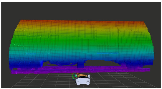
Figure 22.
Octomap with 5 cm resolution, showing only the 5 m section directly above the robot.
The Planning Scene of MoveIt in the robot manipulator controller integrates the Octomap for obstacle detection. During path planning, MoveIt’s planning algorithm (e.g., RRTConnect) computes a safe trajectory from the start to the target point, utilizing the robot’s kinematic model and obstacle data from the Octomap. This ensures that the manipulator avoids obstacles during its movement. In this study, the longset valid segment fraction parameter of RRTConnect for motion discretization is set to 0.01, and the maximum step length for random sampling is set to 0.1, in order to adapt to the confined space of the inspection channel. This approach offers an efficient, flexible, and precise path planning solution, which is crucial for robotic operations in confined environments, such as metro undercarriage inspection ducts.
3.7. Summary of System Configuration
Given the complexity and scale of metro underframe inspection, the simulation system development involves multiple aspects. Here is a summary of the development work in a Gazebo-based simulation system:
- The Environmental Data Collection module manually collects point cloud data of the inspection scene.
- The Point Cloud Processing module uses algorithm-assisted automatic processing plus manual fine-tuning.
- The Environmental Modeling module generates a grid-based model via software, with manual fine-tuning.
- The Robot Modeling module manually creates a robot URDF model.
- The Goal Vectorization module manually marks inspection targets.
- The Safety Module performs robot collision detection, with manual parameter configuration.
In the development of a simulation system based on Gazebo, the configuration and collaborative work of the modules are crucial for the system’s efficiency. The environmental data acquisition module manually collects point cloud data of the inspection scene, offering basic environmental information for the simulation system. By applying point cloud fusion technology, the integrity and accuracy of the collected data are ensured, providing precise environmental features for subsequent scene modeling and robot motion. The point cloud processing module combines algorithm-based automatic processing with manual fine-tuning. It completes the alignment, splicing, and cutting of environmental point cloud data, generating a continuous and complete dataset, improving data quality, and laying the foundation for modeling and simulation. The environmental modeling module uses Geomagic software to transform the processed point cloud data into a mesh model. Normal vector reversal processing is employed to solve the mesh model hole problem, ensuring good model display and addressing the issue of Gazebo’s inability to directly import point cloud data. The robot modeling module manually creates a URDF model of the robot and configures its physical properties and parameters to guarantee correct robot motion and control accuracy in the simulation environment. The target vectorization module utilizes a vectorization labeling platform to manually mark inspection targets. Operators can directly mark inspection points in the point cloud data, providing data support for robot navigation and manipulator operation. The safety module handles robot collision detection, with relevant parameters configured manually. Vehicle undercarriage point cloud data is converted into a 3D voxel data format and analyzed using ROS’s MoveIt tool. This enables safe motion planning of the manipulator in complex environments, avoiding collisions and ensuring inspection task execution. Running the robot in the simulation environment and performing preset inspection tasks verifies the accuracy of the robot model and the effectiveness of the control system. The collision detection function of the safety module performed well in multiple experiments, effectively preventing robot-environment collisions and ensuring the safety and reliability of the simulation process.
4. ISAAC SIM-Based Simulation System Development
In the field of robot simulation, Gazebo, a widely used open-source tool, has several limitations, particularly in handling large-scale point cloud data. Its tendency to lag and crash is due to insufficient data processing efficiency and graphics rendering capabilities. Moreover, Gazebo is inadequate in providing precise physics simulation and rich sensor data, which are crucial for complex robot applications. Its graphics rendering is not realistic and fails to offer a visual experience on par with real-world scenarios. Moreover, Gazebo’s integration with other development tools and AI frameworks is limited, restricting the flexibility and efficiency of the development process.
In order to address these limitations, the project developed a new simulation system for undercarriage robots based on NVIDIA’s Isaac Sim 4.5, which was released in January 2025. This system aims to improve the efficiency and precision of undercarriage inspection robot development. Importantly, the adoption of the Isaac Sim platform leverages its AI framework and deep learning capabilities, which are crucial for algorithm development and large model training.
NVIDIA Isaac Sim offers significant advantages compared to Gazebo. Built on the NVIDIA Omniverse platform, it combines advanced real-time rendering and physics engines to create highly realistic virtual environments. The simulation of lighting, materials, and physical reactions closely mirrors reality, providing robots with a more accurate perception and interaction experience. With GPU-accelerated computing, Isaac Sim greatly improves simulation efficiency, especially in complex scenes and large-scale datasets. It is also deeply integrated with NVIDIA’s AI ecosystem, including tools like CUDA, cuDNN, and TensorRT, offering robust support for AI model training and inference. This integration accelerates data processing and algorithm development, significantly enhancing robot intelligence. In undercarriage inspection tasks, Isaac Sim can more efficiently simulate robot movements and sensing in confined and complex environments, aiding in the optimization of path planning and obstacle avoidance strategies. This provides a superior platform for robot development and testing.
Gazebo is suitable for initial system design and algorithm development due to its open-source nature and deep ROS integration. Isaac Sim excels in the fine-grained simulation of complex scenes with its real-time rendering and high-precision physics engine. This study leverages both platforms by first conducting preliminary design and algorithm development in Gazebo. Then, it moves to Isaac Sim for in-depth optimization and validation. This progressive simulation-based development approach aims to maximize the advantages of both platforms. Thus, it can achieve more efficient and accurate simulation results.
4.1. Simulation Scenario Construction
In the previous section, the Gazebo simulation platform only imported the undercarriage components of a single metro carriage model. This simplification was necessary due to Gazebo’s sensitivity to the size of model files. When the file size exceeds 100 MB, Gazebo’s frame rate significantly drops, adversely affecting real-time simulation performance. Therefore, lightweight modeling is essential for maintaining efficient simulation performance in Gazebo.
In contrast, the Isaac Sim platform effectively addresses this limitation. Under the same hardware conditions, Isaac Sim can load complex models with rich textures and various materials. By utilizing RTX real-time ray tracing and DLSS technologies, it delivers highly realistic lighting and material simulations, significantly enhancing visual fidelity and providing a more authentic interaction environment for both robots and users.
However, models derived from point cloud reverse engineering and meshing often suffer from deformations and lack of color information, limiting their applicability in high-precision simulations. To fully leverage Isaac Sim’s capabilities and meet the project’s accuracy requirements, this study used 3DMax to create a high-precision USD-format metro vehicle model, as shown in Figure 23. This model faithfully reproduces the details and material characteristics of a real metro undercarriage, providing a more reliable foundation for subsequent simulations.
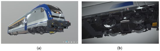
Figure 23.
A metro model with rich material and texture information: (a) Overall View. (b) Bogie details.
To create the railway and duct models, the dimensions of the real ducts were first measured, and the inspection duct was then modeled based on these measurements. Similarly, 3DMax was used to create a duct environment model with corresponding materials and textures. The vehicle and duct models were then combined. Leveraging Isaac Sim’s resources and real metro inspection requirements, the scene layout was designed. The metro vehicle was placed on the tracks, and elements such as platforms, tunnels, signals, and overhead lines were arranged to replicate a real metro operation environment. Using Isaac Sim’s lighting and material systems, appropriate lighting conditions and material properties were configured. By adjusting parameters such as light source position, intensity, and color, along with material reflectivity, refractivity, and roughness, realistic lighting and material effects were achieved, enhancing the scene’s visual fidelity. To enhance simulation efficiency for a large-scale scenario, the scene parameter configuration has been optimized in the following ways. First, the Anti-Aliasing setting was downgraded from TAA 8x to TAA 2x to increase the frame rate. Second, during runtime, the Shadow Resolution is adjusted based on the system’s hardware capabilities, which were either reduced or disabled. Similarly, the Screen Space Reflections quality is enabled or disabled according to hardware requirements. Additionally, the simulation environment utilizes the default natural light settings. As a result, the metro inspection scenario model shown in Figure 24 was completed.
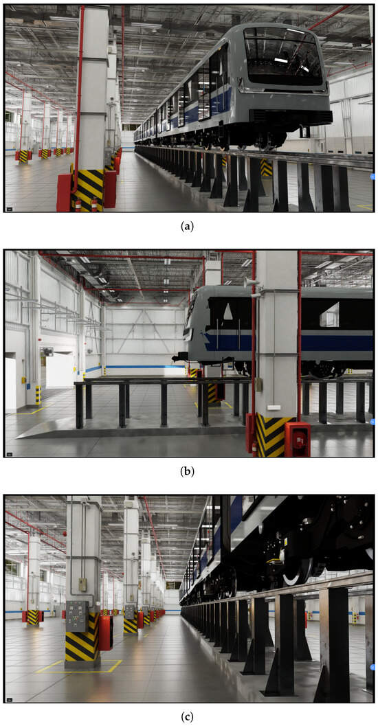
Figure 24.
The metro inspection scenario model built using Isaac Sim’s powerful rendering capabilities: (a) Overall view. (b) Side view. (c) Inspection duct.
Figure 24 demonstrates the scene’s high rendering quality. The powerful engine enables realistic simulations of lighting, shadows, and material effects. The model also includes a high-precision collision detection system, with physical properties such as friction and hardness adjustable to match real-world conditions.
For users with hardware limitations, system performance can be improved by reducing lighting and material parameters that have minimal impact on robot operations. This can be performed by adjusting the simulator’s rendering settings.
4.2. Robot Modeling
4.2.1. Robot Model Import
The URDF model of the robot, developed for Gazebo simulation, can be directly imported and run in Isaac Sim. To do this, perform the following:
- Open the extension window in Isaac Sim via “Window” -> “Extensions” and enable the URDF plugin by searching for “URDF” in the search box.
- Access the URDF Importer tool through “Isaac Utils” -> “Workflows” -> “URDF Importer” to prepare for model import.
- Before importing, configure the import options meticulously, including merging fixed joints, fixing the base link, setting inertia tensors, unit scale factors, and joint drive types and parameters.
- After completing the settings, import the URDF model into the simulation environment. To ensure the model’s physical interaction characteristics are accurately represented, visualize the collision mesh for verification.
The correctly imported robot is shown in Figure 25. Compared to Gazebo models, those in Isaac Sim allow for richer details. For instance, the simulated laser radar in Isaac Sim can fully showcase its appearance and component details. In contrast, Gazebo might simplify complex laser radar models to cylinders. Moreover, the robot’s material textures can be displayed with varying visual effects based on real-world reflection results.
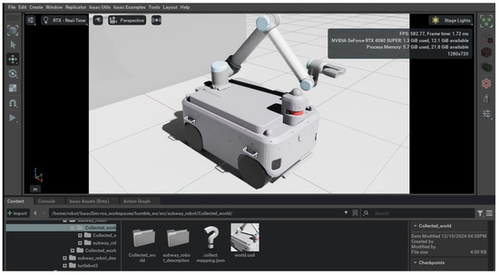
Figure 25.
The robot model that has not undergone appearance material settings after being imported into Isaac Sim.
In this project, since a mobile robot is used, additional configuration steps are required when importing the URDF model into Isaac Sim to ensure model accuracy and simulation efficiency.
First, the URDF file must fully describe the physical structure of the robot, including the mobile base, manipulator, camera, radar, and sensors. During the import process, the model is automatically converted to USD format. The hierarchy of the USD model file must then be manually adjusted to ensure each component has an independent level for precise control.
Second, for mobile robots, the “Fix Base Link” option must be unchecked to allow movement in the simulation. The joint drive type should also be set to velocity mode for more accurate motion simulation.
Finally, to enhance simulation realism and reliability, the drive strength parameters of all joints in the mobile base and manipulator must be adjusted to match those of the actual robot, ensuring the simulation accurately reflects real-world performance.
The Physically Based Rendering (PBR) parameters of the robot are imported through the model description file in the robot URDF. Currently, no additional material settings for the robot model are implemented in Isaac Sim. The friction coefficients of the robot’s wheels and the ground are set to their default values.
4.2.2. Manipulator Module
Configuring the imported URDF manipulator in Isaac Sim involves several key steps:
- Adjust Physical Properties: Begin by checking and adjusting the physical properties of each link, such as mass and inertia matrices, to ensure accurate physical simulation.
- Verify Joint Types: Confirm that the joint types match the actual manipulator and set the joint drive types and parameters in the properties panel. This includes defining joint motion ranges to prevent exceeding physical limits.
- Enable Collision Detection: Enable collision detection for each link and assign appropriate collision shapes to ensure precise collision detection during the simulation.
- Adjust Visual Properties: Modify the visual properties of the manipulator, such as color and material, to enhance the appearance. Additionally, optimize rendering performance if necessary.
- Add Controllers: Add the appropriate controllers and write control logic using Isaac Sim’s programming interface to enable joint motion control and trajectory planning.
- Run and Test Simulations: Finally, run simulations to observe the manipulator’s motion and physical behavior. Verify that it meets expectations and refine the model and configuration based on test results.
As depicted in Figure 26, the manipulator controller is configured via Python scripting. Figure 27a illustrates the configuration of the joint physical properties, which includes setting parameters such as joint rotation type, damping coefficient, and maximum torque. Figure 27b shows the configuration of the manipulator controller parameters, focusing on the setup of the controller’s PID parameters.
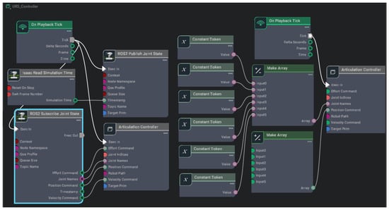
Figure 26.
The configuration diagram of the Manipulator node in Isaac Sim.
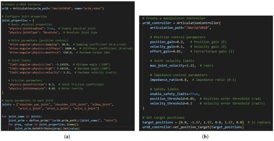
Figure 27.
Manipulator configuration: (a) Joint parameter details. (b) Manipulator controller parameters.
In Isaac Sim, the manipulator, acting as an actuator, is controlled by the MoveIt controller in ROS. In MoveIt, the manipulator’s motion trajectory is calculated by manually adjusting its posture. This trajectory is then transmitted via the ROS system to the manipulator in Isaac Sim for execution. Additionally, when computing the manipulator’s trajectory, MoveIt has completed safe path planning based on the Octomap data of the metro inspection channel and undercarriage. This ensures that the manipulator does not collide with the robot body or surrounding environment during motion.
4.2.3. Communication Module
To control the robot and manipulator within the simulation environment, a communication bridge between the Isaac Sim simulator and ROS 2 is essential. This is achieved using a dedicated ROS 2 bridge plugin. The key configuration step involves matching the topic names for the robot and manipulator control nodes in both Isaac Sim and ROS 2.
For example, as shown in Figure 28, the manipulator control follows these steps:
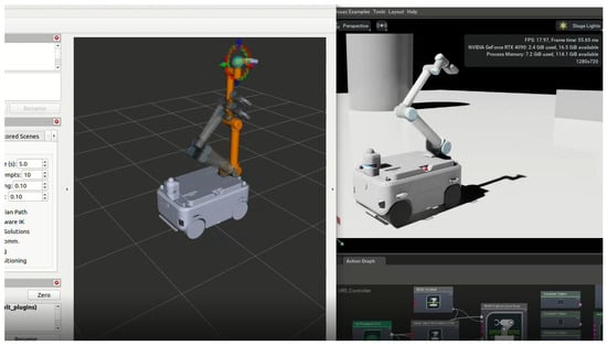
Figure 28.
ROS and Isaac Sim communicate to enable MoveIt control of the manipulator.
- MoveIt Control in ROS 2: In ROS 2, MoveIt is used for planning and controlling the manipulator. Motion commands are generated and sent to the manipulator.
- Motion Command Relay: The motion commands are transmitted to Isaac Sim through the ROS 2 bridge, where the simulator executes the corresponding movements.
- State Data Feedback: The manipulator’s state data (such as joint position, velocity, and other relevant metrics) is sent back to ROS 2 through the same bridge.
- Monitoring with RVIZ: Tools like RVIZ in ROS 2 can be used to visualize and monitor the manipulator’s motion, providing real-time feedback about its current position and state.
By establishing this communication bridge, seamless control and monitoring of the manipulator and robot within the simulation environment is ensured. This setup also supports the efficient integration of ROS 2-based algorithms, control systems, and visualization tools, improving the overall simulation experience.
4.2.4. Sensor Configuration
Isaac Sim provides diverse sensors. These can be placed on designated links via plugins and activated after setting key parameters. For instance, cameras require settings for image resolution, frame rate, field of view (FOV), and focal length. LiDAR needs configuration for horizontal and vertical scanning angles, number of scan lines, scans per second, and maximum measurement distance.
Once configured, set the sensor data publication frequency and output topic names to meet the robot’s control and data processing needs. Also, configure the data output format, such as RGB for cameras and point clouds for LiDAR. Then, use Isaac Sim’s ROS 2 bridge to establish communication between Isaac Sim and ROS 2, enabling algorithm and simulator interaction.
Note that Isaac Sim currently only supports 3D LiDAR. In this project, the undercarriage robot also has 2D LiDAR. Hence, the 3D point cloud data must be preprocessed with filtering and coordinate transformation to project it onto a horizontal plane. Convert the resulting point cloud data into polar coordinates to calculate the shortest distance for each angle, generating 2D LiDAR scan data. Finally, publish this 2D data to ROS 2 topics for localization and navigation algorithms. The converted data is shown in Figure 29.
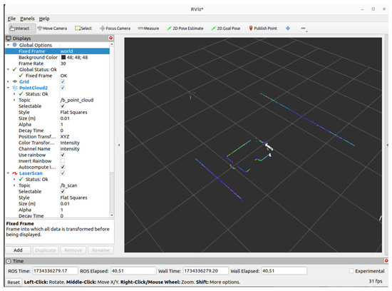
Figure 29.
Two-dimensional LiDAR data simulated via algorithm processing.
4.3. System Integration
The robot used in this study comprises a differential-drive base controller, a 6-DOF manipulator, an end-of-arm camera, and key components like LiDAR and IMU. In the Isaac Sim simulation environment, it is required to configure and develop interfaces for each component that are compatible with Isaac Sim and the ROS system.
In terms of motion control, the robot’s moving base in Isaac Sim is adjusted by receiving velocity commands from ROS. In ROS, the robot’s linear and angular velocity information is published via the “/cmd_vel” topic. This precisely controls the wheel speeds of the differential-drive base, enabling the robot to translate and rotate and ensuring it follows the designated path. The manipulator is controlled using ROS’s MoveIt. The manipulator joint-state publishing interface in Isaac Sim sends current joint angles and status to MoveIt via ROS. At the same time, the motion-planning objective interface built in Isaac Sim receives joint target positions or end-effector poses planned by MoveIt.
For sensor interfaces, the data collected by the LiDAR in Isaac Sim is published to the “/scan” topic via the ROS interface. Using the “sensor_msgs/LaserScan” message format, it publishes point-cloud data, including measurement range, angular resolution, and scanning angle, providing environmental perception for localization and navigation. Camera image data is published by ROS after conversion. For RGB images, the detection camera at the end of the manipulator in Isaac Sim publishes image data to the “/camera/image_raw” topic. This topic uses the “sensor_msgs/Image” format for raw image data. The “/camera/camera_info” topic publishes camera intrinsic parameters in the “sensor_msgs/CameraInfo” format. These parameters are used for image correction and geometric calculations by image-processing algorithms. Image-detection algorithms in ROS subscribe to image topics to acquire and process images.
When the simulation system operates, first start Isaac Sim to load the robot and sensor models, then start the functional nodes in ROS. Sensors in Isaac Sim collect and publish data to the ROS network in real time. The localization and navigation algorithm node subscribes to LiDAR data and combines it with the robot’s kinematic model and map to determine the position and plan a path. Then, it generates velocity commands to control the robot’s movement. The image-processing algorithm node receives image data, preprocesses it, and uses target-detection algorithms to identify targets and coordinate manipulator operations. The manipulator control node receives motion-planning commands and controls the manipulator to perform tasks.
During robot motion, the chassis control node feeds back the actual motion status. The localization and navigation algorithm node uses this feedback to correct positioning errors and optimize path planning. The manipulator control node feeds back joint states, prompting MoveIt and other nodes to adjust planning strategies and ensure stable system operation.
The system implementation process is shown in Figure 30; all modules and functions of the simulation system must be manually developed, with the implementation process as follows: First, the joints of the simulated robot are set up, defining their degrees of freedom and motion ranges. The physical properties, such as mass and inertia matrices, are configured to ensure realistic motion. Next, a control connection to the robot is established, and control parameters are set for precise motion management. Following this, the robot configuration is completed, including sensor and actuator settings, creating a basic platform for subsequent experiments. At the same time, the simulation environment is configured by adjusting parameters like gravity and friction and defining environmental properties such as ground material and air resistance, thus ensuring reliable simulation results. Additionally, simulation data is labeled, and a data labeling system is designed for traceability and easier management and analysis. Then, the simulation environment is built to meet experimental requirements, including scene construction, obstacle addition, and lighting and texture adjustments, facilitating robot motion and data collection. Robot simulations are run in this environment using a physics engine and control algorithms to generate training data, including robot motion trajectories and sensor data. The collected simulation data is processed through synthesis and data augmentation to enhance dataset diversity and applicability. Pre-trained models are fine-tuned using the synthetic data, optimizing model performance with deep-learning frameworks to improve adaptability for specific tasks. Finally, the trained model’s performance is evaluated using a validation set to test its accuracy and generalization ability, with performance analyzed through key indicators.
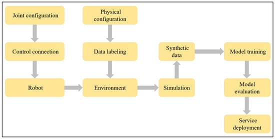
Figure 30.
System implementation process.
In this study, our goal is to leverage Isaac Sim’s powerful simulation and deep learning capabilities to build a robotics simulation system that integrates virtual and real-world data, providing technical support for training large-scale object detection models for undercarriage inspection robots. As shown in Figure 31, the model training process focuses on improving performance through the synergy of simulated and real-world data. The system first collects data in virtual environments using robots, including sensor information from area-array laser cameras and RGB cameras. This data is transmitted to the image processing module via ROS bridges. Meanwhile, real robots operating in physical environments send their sensor data to the same ROS bridges. Virtual and real data are then fused at the ROS bridges to generate composite datasets for training visual detection models. The trained models are rigorously evaluated and optimized based on performance metrics. Finally, optimized models are deployed to physical robots, significantly enhancing detection capabilities. This simulation-to-reality workflow addresses real-world data scarcity while improving model generalizability and adaptability.
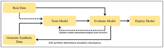
Figure 31.
Simulation-to-real-world workflow.
The project thoroughly tested the undercarriage robot inspection process in Isaac Sim. As shown in Figure 32, the robot starts inspecting the metro vehicle. Even with large-scale, high-fidelity simulations running, the simulator delivers great visual effects, ensuring smooth data flow and seamless user interaction. This significantly improves the efficiency and coverage of offline teaching.
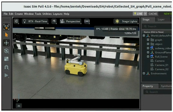
Figure 32.
The robot moves along the side of the metro undercarriage in Isaac Sim.
4.4. Discussion on System Operation Status
This study monitored the computer system status during the operation of Gazebo and Isaac Sim simulations, with performance parameters shown in Figure 33. Gazebo simulations ran at 62.47 FPS, indicating smooth operation and efficient hardware resource usage. In contrast, Isaac Sim simulations had a much lower frame rate of 11.28 FPS. This difference is mainly due to the varying levels of graphic-rendering complexity and physics-engine precision between the two platforms. Isaac Sim’s demand for GPU resources is high, owing to its high-fidelity graphic rendering and advanced physics engine. This results in significantly increased GPU memory usage during operation, reaching 11721 MiB, which is much higher than the 4071 MiB used during Gazebo simulations. Meanwhile, Isaac Sim simulations also show relatively higher GPU power consumption and temperature, reflecting its intensive use of computing resources.
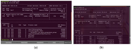
Figure 33.
GPU usageduring the operation of the two simulation systems: (a) GPU usage during the operation of the Gazebo simulation. (b) GPU usage during the operation of Isaac Sim.
Under the same hardware conditions, Isaac Sim has a lower simulation frame rate and noticeable visual lag. Although using a high performance GPU can speed up its operation, this will also increase costs. Therefore, in the verification of positioning and navigation algorithms, debugging of manipulator control algorithms, and research on offline teaching schemes, this study mainly uses the Gazebo simulation platform. In contrast, the Isaac Sim platform is employed when high-precision rendering of scenes is required.
5. Offline Teaching
Offline teaching is essential in industrial robotics. It allows operators to program robot motions and tasks in a virtual simulation without using on-site robot resources. This avoids interference with real-world processes and enhances efficiency, enabling rapid iteration and optimization of programs. As a result, on-site deployment and debugging times are significantly reduced. By improving development efficiency, safety, and flexibility, offline teaching plays a crucial role in advancing industrial automation. It also helps cut training and integration costs.
Currently, the teaching work of the undercarriage inspection robot mainly depends on manual operation. According to the feedback from the on-site workers, for a metro with 8 carriages, manual teaching of the manipulator needs to be performed at least 1200 times. The on-site teaching staff work for about 10 h a day, and it takes about 13 days to finish the teaching work for the whole 8-carriage train. The result of manual teaching shows that it takes an average of 5 to 6 min to complete one action of the manipulator through manual teaching, which means about 10 teaching actions can be performed per hour.
This study focuses on the development and design of an offline teaching scheme for undercarriage inspection robots, selecting a Gazebo-based simulation platform as the development environment. Gazebo’s deep integration with ROS enables quick environment and robot modeling, smooth deployment, and efficient robot control and sensor data collection via ROS’s communication framework, lowering system development complexity. Compared to Isaac Sim’s complicated processes, Gazebo offers a more streamlined platform for optimizing algorithms and controllers. After completing the Gazebo-based offline teaching system and algorithm optimization, robots can be swiftly deployed in Isaac Sim’s high-fidelity simulations, leveraging its superior rendering and physics engine to enhance user experience. To comprehensively evaluate the feasibility of the proposed offline teaching scheme, robot inspection tasks were first simulated and tested in the virtual environment, with a series of experiments conducted to validate the approach under ideal conditions. Subsequently, the scheme was applied to real-world scenarios for thorough validation, confirming its effectiveness and reliability in operational settings and ensuring that the research outcomes can be successfully translated into practical applications.
This study addresses the inefficiency of on-site robot teaching through an offline teaching solution. By pre-planning robot paths and manipulator motions in a simulation environment, time and labor requirements for on-site teaching can be significantly reduced. The design focuses on robot motion safety in complex environments and task accuracy. It uses a simulation system to optimize navigation point setup, manipulator teleoperation, and automatic data recording. These steps ensure the feasibility and effectiveness of the offline teaching solution.
5.1. Research on Offline Teaching
The offline teaching scheme for metro inspection proposed in this paper is as follows:
- (1)
- Simulation environment setup: Build a complete six-carriage inspection environment in the Gazebo simulation system and import the processed undercarriage and inspection-point models;
- (2)
- Import inspection points: Import the inspection-point coordinates generated by the vectorization annotation software into the simulation system and mark all inspection points on the undercarriage model;
- (3)
- Robot navigation points setup: Set navigation points every 3 m between carriages for the robot to teach manipulator actions sequentially;
- (4)
- Manipulator remote control: Operators remotely control the manipulator in the simulation to move it to each inspection point;
- (5)
- Data capture and data recording: At each point, the manipulator performs shooting actions, and the simulation system records its posture and shooting data;
- (6)
- Data processing and path planning: Process the recorded data to generate manipulator motion paths with collision detection and optimization;
- (7)
- Multi-person collaboration: Enable multiple operators to teach simultaneously, improving programming efficiency.
Figure 34 illustrates the simulation test scenario in Gazebo, developed during the offline teaching process. It includes meshed models of the metro undercarriage and ducts. The robot controller has loaded the 3D Octomap of the metro and ducts to plan safe paths for the robot.
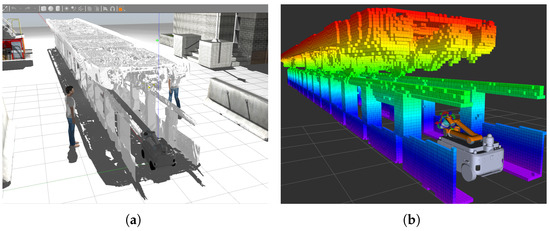
Figure 34.
Offline teaching simulation scenario: (a) The working scenario built in Gazebo. (b) The Octomap environmental information loaded by the manipulator controller when the robot is in the inspection duct.
Offline teaching involves remotely operating the manipulator in simulation to reach inspection points marked on the vectorization platform and acquire visual data. This stage is the most time-consuming part of the process. However, compared to the approximately 180 s required per point during on-site manual operations, the offline teaching process takes only around 10 s per point, significantly improving teaching efficiency.
As shown in Figure 35, the simulation depicts the robot inspecting the metro undercarriage. The robot uses the end-effector-mounted camera to capture images of the inspection targets, which are visualized as yellow cubes based on the vectorization platform annotations.
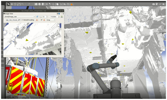
Figure 35.
The image of the metro undercarriage by the camera in the simulation.
Figure 36 illustrates the 3D Octomap rendered in RViz, which provides critical environmental data to support manipulator control during undercarriage operations. To address challenges such as localization and navigation algorithm inaccuracies and potential robot malfunctions, the manipulator controller performs path planning based on real-time environmental information before each action, thereby guaranteeing collision-free trajectories. This strategy effectively enhances system safety and improves the overall reliability of manipulator operations.
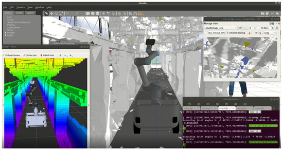
Figure 36.
Manipulator path planning based on 3D octomap.
After acquiring images from all inspection points, the simulation system preserves the data from the cameras at the end of the robot manipulators, as shown in Figure 37. This data is then used for subsequent manual confirmation and the deployment of image-processing algorithms to evaluate the inspection results.
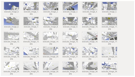
Figure 37.
RGB images of inspection targets acquired through offline teaching.
Finally, this paper tests an offline teaching scheme using a metro model with six carriages. These six carriages involve 960 manipulator actions. The test shows that offline teaching takes 9 h in total. It takes about 30 s to program each action, compared to the 5–6 min needed on site. The teaching efficiency is greatly improved.
5.2. Experimental Verification
To verify the feasibility of the offline teaching scheme, this study conducted a comprehensive validation experiment at the research facility, taking into account the safety requirements associated with real-world metro inspection scenarios. As the actual metro robots were already deployed in the field during this phase, a compact wheeled inspection robot was used to perform gauge inspections within the research center. The validation procedure involved the following steps: First, 3D laser scanning technology was employed to construct a detailed point cloud model of the research facility. Next, a vectorization tool was used to accurately annotate gauge positions within the point cloud. These annotated targets were then used in the simulation environment to conduct offline teaching, during which navigation waypoints and corresponding robot pose data were generated and stored. Finally, the generated data were transferred to the real robot for execution. The effectiveness of the proposed approach was validated through a comparison between the executed robot trajectories and the offline-taught annotations.
As shown in Figure 38, the navigation points and corresponding camera and gimbal poses were obtained through offline teaching in the simulation environment. These results were successfully deployed on the real robot, which accurately captured images of the inspection targets (i.e., streetlights) using the predefined waypoints and poses.
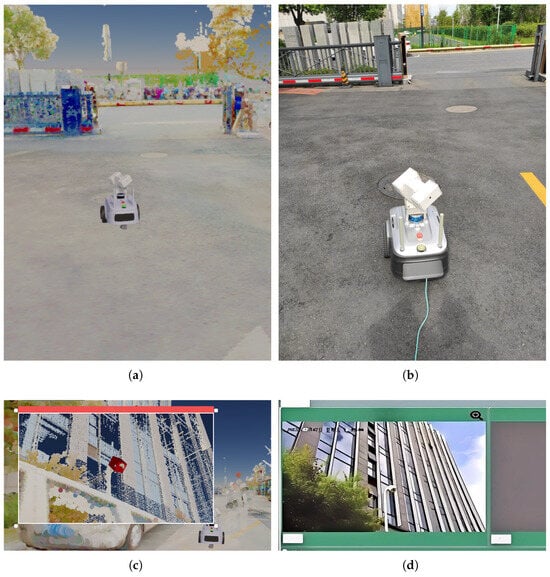
Figure 38.
Offline teaching experiment: (a) The pose of the robot during offline teaching. (b) The pose of the actual robot when executing the offline teaching task. (c) The target captured during offline teaching. (d) The target captured by the actual robot when executing the offline teaching task.
In this study, offline teaching was performed for 44 inspection targets located within a park environment. The corresponding trajectories and poses generated in the simulation were subsequently executed by the real robot. A successful capture was defined as one in which the target appeared clearly, completely, and centrally within the captured image. The inspection outcomes for all 44 targets, based on this evaluation criterion, are summarized in Table 4.
Table 4.
Scheme verification results.
The data presented in the table indicates that the offline teaching approach achieved a success rate of 84%. Further analysis and repeated testing revealed that the primary causes of failure are cumulative system errors and suboptimal camera parameter configurations. As illustrated in Figure 39, inaccurate environment modeling during the offline teaching process can lead to positional deviations, resulting in incomplete or misaligned inspection images.
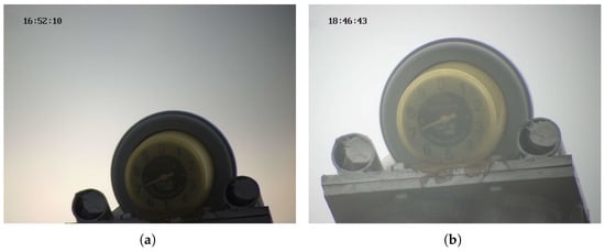
Figure 39.
The deviation comparison chart of the target captured: (a) Target image captured after offline teaching. (b) Standard target image.
To further verify the system’s accuracy, two validation experiments were conducted at the research center using a robot. One experiment involved the robot’s camera photographing gauges, and the other used an infrared camera to measure the temperature of power transmission equipment. These two methods comprehensively verified the intelligent inspection target vectorization module and offline teaching scheme. The specific results are presented in Table 5.
Table 5.
Verification results of infrared and visible light imaging.
Figure 40 presents infrared images captured during the validation of the offline teaching tool and scheme, covering both qualified and disqualified (due to blurriness) infrared images. The blurriness is mainly attributed to the navigation point errors in the simulation system, resulting in inaccurate camera focusing.
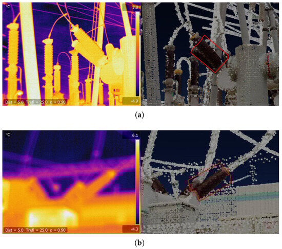
Figure 40.
Infrared temperature measurement experiment. The left is the image taken by the robot. The right is the patrol target selected during vectorized marking in the offline programming system: (a) Image meeting the inspection requirements. (b) Images rendered unusable due to blurriness.
Figure 41 shows photos of unqualified meters taken by a visible light camera during offline teaching result implementation. In Figure 41a, the obvious shooting angle deviation makes data unreadable. This is due to navigation point offsets from simulation system errors, causing incorrect teaching. Figure 41b is blurry and unusable because of the wrong camera focus settings in offline teaching.
Figure 41.
Images of visible light camera shooting failures: (a) Target shooting failures due to large angle deviations. (b) Blurred images due to incorrect camera parameters.
This paper has conducted a detailed analysis of the simulation system’s modules to explore the sources of errors in offline teaching. The following aspects are found to be prone to errors:
- Inaccurate environmental mapping;
- Point cloud meshing errors in road surface modeling;
- Discrepancies in wheel compliance modeling between the simulation and the real robot;
- Coordinate system misalignment in the undercarriage model;
- Differences between the simulated and actual hardware, including the installation positions of the LiDAR, gimbal, and camera;
- Variations in camera intrinsic parameters caused by differences in focal length, zoom, and aperture settings;
- Localization and navigation inaccuracies.
Scene modeling errors and camera parameter configuration issues in offline teaching are the main sources of error. In addition, dynamically and accurately setting the camera focal length in simulations presents significant challenges.
Aiming at the errors caused by the above issues, this paper proposes a manual correction scheme, which is as follows:
- Manual adjustment of navigation points: In offline teaching, if there are obstructions at navigation points or the pan-tilt-zoom (PTZ) reaches its extreme angle, these navigation points should be manually adjusted. After moving the robot to a suitable position remotely, the original navigation points should be covered. This operation can optimize the robot’s position, reduce the risk of the target being blocked, and improve the efficiency and accuracy of teaching.
- Manual correction scheme: Adjust the camera parameters manually based on the distance between the inspection target and the camera. During offline teaching, ensure that the inspection target is centered in the image and occupies no more than 50% of the image area. By reasonably controlling the position and proportion of the target in the image, this scheme effectively increases the fault-tolerance rate of shooting and improves the accuracy of teaching.
In the experimental validation of the offline teaching solution, this study not only assessed the feasibility of the solution but also focused on its stability and reliability under different conditions. The experimental results showed that the solution achieved high success in acquiring RGB images of inspection targets, with an average pass rate of 84%, thus confirming its effectiveness, especially in improving teaching efficiency. Through multiple experiments targeting different targets, the adaptability of the offline teaching solution under different distances and angles was verified. For example, within the farthest distance of 7 m, the solution could still maintain good shooting effects, indicating its strong applicability. Despite the presence of system errors and camera parameter setting issues, the accuracy of teaching was significantly improved through a manual correction solution. Specifically, for the pan-tilt posture deviation caused by modeling accuracy issues, a method of manually adjusting navigation points and camera parameters was adopted, making the captured images more complete and clear.
In addition, two validation experiments were carried out in this study: one was to use the robot’s camera to shoot meters, and the other was to use an infrared camera to measure the temperature of transmission equipment. These experiments further confirmed the reliability of the vectorization labeling results and the offline teaching solution. In the test of 621 infrared images and 51 visible light images, the success rate of the infrared camera reached 95%, and that of the visible light camera was 86%. The reasons for the failures mainly focused on image blurring and target deviation from the image center, most of which could be solved by optimizing the navigation point settings and adjusting the camera focus. Note that the current experiment only focuses on the success rate and efficiency of offline teaching. It does not calculate the pose deviation between reality and simulation using the acquired point cloud data and RGB images.
5.3. System Limitations Analysis and Discussion
5.3.1. Simulation-to-Reality Discrepancy Analysis
When modeling the environment with laser point clouds, we used two Trimble X7 terrestrial laser scanners due to the six-car metro’s great length. In data processing, we had to stitch together data from multiple stations for each scanner and also merge the point cloud data from both scanners. Although the scanners have automatic registration algorithms, manual fine-tuning is still needed to ensure the tracks and cars are straight, which inevitably introduces some registration errors. Laser scanning, while capturing rich data, struggles to record minute ground irregularities and facility wear, causing model-reality discrepancies.
Metro modeling also faces precision challenges. The metro’s complex design, along with manufacturing and assembly errors, creates differences between the actual and design models. Long-term wear and tear exacerbate this. Robot modeling precision is also affected by mechanical component and assembly errors, leading to discrepancies in dimensions, structure, and dynamics between the actual robot and the simulation model.
Sensor data accuracy in simulations is another key factor causing deviations. Gazebo can apply Gaussian noise to sensors, and Isaac Sim can add more noise types like uniform and signal interference noise. But real sensors can be affected by unmodeled factors like electromagnetic interference. Also, simplified sensor characteristics in simulations can result in discrepancies between simulated and real sensor data.
5.3.2. Discussion of Solutions
During LiDAR point cloud data processing, manual refinement post-algorithmic automation was adopted to enhance data accuracy, yet human adjustment precision remains limited. To tackle data incompleteness and precision shortcomings, future research plans to employ dynamic neural radiance field (Dynamic NeRF) technology for LiDAR data augmentation [50,51,52]. Given the undercarriage’s complexity with occlusion and noise, data augmentation will boost the model’s adaptability and robustness. By leveraging existing point cloud data and scene context, Dynamic NeRF can estimate occluded areas, completing missing geometric and appearance information. This improves model integrity and accuracy, aiding real-scene modeling. Moreover, Dynamic NeRF’s high-resolution modeling will optimize local details of key and problematic metro undercarriage components. Finer sampling and modeling of these areas will highlight their features, enabling better detection and assessment of wear and loosening, thus supporting vehicle maintenance.
Regarding robot modeling and sensor errors causing simulation imprecision, this study’s offline robot teaching is primarily affected. To address this, strict operational constraints were set in offline teaching:
- The movement of the manipulator’s elbow joint must maintain a minimum safety distance of 5 cm from the undercarriage channel to prevent collisions that may result from operational errors.
- When shooting inspection targets, centrally position them in the image via arm operation and adjust shooting distance to limit their proportion in the frame.
These measures aim to boost offline teaching’s fault tolerance and facilitate on-site validation and correction of teaching results.
6. Conclusions
This study has achieved core outcomes by focusing on the practical application requirements of intelligent undercarriage inspection robots in urban rail transit.
First, two simulation systems with unique advantages were developed. The paper provides a comprehensive overview of the simulation system’s framework. It also covers subsystem design approaches. Additionally, it offers modeling and data processing techniques tailored for metro inspection scenarios. The paper also provides solutions to the challenges encountered during system development. These simulation systems underpin the proposed methods and solutions. The Gazebo-ROS framework enables rapid algorithm prototyping, especially for navigation, imaging, and control optimization. Its low computational overhead and ROS compatibility significantly reduce the development cycle time. Additionally, its low learning cost enhances the system’s practicality. The Isaac Sim-based system delivers excellent real-time rendering and high-precision physics. It accurately simulates complex, large-scale scenes and provides an excellent user experience. Future functional expansion can be achieved using the deep learning and AI features of Isaac Sim. The Gazebo-based simulation system strongly supports robot algorithm development and optimization. After algorithm development and testing in this system, robots can be directly deployed to the Isaac Sim system for further refinement. This achieves simulation effects with rich material textures, good rendering, and comprehensive physical properties.
Second, a structured offline teaching scheme for undercarriage robots was proposed based on these systems. The scheme includes navigation point setup, teleoperated manipulator control, and automatic data recording. It streamlines teaching, reduces operational risks, and cuts deployment time. Experimental results show that it can program a single manipulator motion in about 30 s, which is 10 times faster than manual on-site teaching. This scheme offers an innovative approach for rail transit’s intelligent operation and maintenance.
The paper introduces simulation systems and offline teaching methods used in the design and development of undercarriage inspection robots in the rail transit industry. It outlines the design methods, technical challenges, and solutions for each subsystem. The feasibility of offline teaching within simulation systems is demonstrated through experiments, and the scheme’s effectiveness is confirmed by deploying the teaching outcomes onto robots. The study provides new technical tools for the rail transit industry’s intelligent operation and maintenance, reduces costs and risks, and shows strong practical potential.
7. Future Work
This study has laid the preliminary foundation for simulation and offline teaching technologies in intelligent inspection robots for rail transit. However, to meet the increasingly complex operational demands and dynamic challenges of the industry, further research is needed in the following areas:
- (1)
- Currently, laser point cloud data collection is incomplete, and data processing is inefficient, especially for large-scale scene reconstruction. Future work will focus on dynamic NeRF technology to develop a fast, convenient, and high-precision scene modeling method. This will improve modeling speed and accuracy and enhance simulation system scene reality and applicability.
- (2)
- Given the insufficient precision of direct point cloud meshing and the labor-intensive nature of manual 3D model reconstruction, exploring optimized methods to generate lightweight yet detailed environmental models could be a promising approach for the future. These models, generated via adaptive geometric simplification and feature retention strategies, will reduce hardware dependency while maintaining practical utility.
- (3)
- In response to the rail transit industry’s urgent need for intelligent operations and maintenance, this study explores ways to enhance simulation system performance for greater effectiveness.
These research directions will not only improve the performance and functionality of simulation systems but also provide strong technical support for the digital transformation and intelligent upgrade of the rail transit industry.
Author Contributions
Conceptualization, C.S., H.W. and S.T.; data curation, C.S. and X.L.; formal analysis, C.S., H.W. and X.L.; funding acquisition, C.S. and H.W.; Investigation, C.S., H.W. and S.T.; Methodology, C.S., H.W., H.J. and X.L.; project administration, C.S.; resources, C.S. and X.L.; software, C.S. and X.L.; supervision, H.W., Z.Y., H.J. and S.T.; validation, C.S. and Z.Y.; visualization, C.S., H.W. and S.T.; writing-original draft, C.S.; writing-review and editing, C.S., H.W., H.J., X.L., Z.Y. and S.T. All authors have read and agreed to the published version of the manuscript.
Funding
This research was funded by the Research and Application of Embodied Intelligence Technology for Inspection Robots in Complex Scenarios, grant number 2025C01012.
Data Availability Statement
The original contributions presented in the study are included in the article. Further inquiries can be directed to the corresponding authors.
Conflicts of Interest
Authors Changhao Sun, Haiteng Wu, Zihe Yang, Xujun Li and Shaohua Tian were employed by the Hangzhou Shenhao Technology Co., Ltd. The remaining authors declare that the research was conducted in the absence of any commercial or financial relationships that could be construed as a potential conflict of interest.
References
- Huang, L.; Li, Y.; Wang, W.; He, Z. Enhanced Detection of Subway Insulator Defects Based on Improved YOLOv5. Appl. Sci. 2023, 13, 13044. [Google Scholar] [CrossRef]
- Bao, X. Urban rail transit present situation and future development trends in China: Overall analysis based on national policies and strategic plans in 2016–2020. Urban Rail Transit 2018, 4, 1–12. [Google Scholar] [CrossRef]
- Tao, S.; Zhang, M.; Wu, J. Big data applications in urban transport research in Chinese cities: An overview. In Big Data Applications in Geography and Planning; Edward Elgar Publishing: Cheltenham, UK, 2021; pp. 220–244. [Google Scholar]
- Zhu, J. Research on urban architecture design based on the concept of smart city. Acad. J. Archit. Geotech. Eng. 2024, 6, 116–122. [Google Scholar]
- Zhang, X.; Fan, T.; Mao, Q.; Zhang, Y. Vehicle-Mounted Rail Patrol Inspection Equipment Using a Combination of Line-Scan Cameras and Lasers. J. Surv. Eng. 2025, 151, 06024003. [Google Scholar] [CrossRef]
- Rahman, M.; Liu, H.; Cardenas, I.D.; Starr, A.; Hall, A.; Anderson, R. A review on the prospects of mobile manipulators for smart maintenance of railway track. Appl. Sci. 2023, 13, 6484. [Google Scholar] [CrossRef]
- Zou, W.; Man, S.S.; Hu, W.; Zhou, S.; Chan, H.S.A. Factors Influencing the Acceptance of Industry 4.0 Technologies in Various Sectors: A Systematic Review and Meta-Analysis. Appl. Sci. 2025, 15, 4866. [Google Scholar] [CrossRef]
- Jourabchi Amirkhizi, P.; Pedrammehr, S.; Pakzad, S.; Shahhoseini, A. Generative Artificial Intelligence in Adaptive Social Manufacturing: A Pathway to Achieving Industry 5.0 Sustainability Goals. Processes 2025, 13, 1174. [Google Scholar] [CrossRef]
- Patrício, L.; Varela, L.; Silveira, Z. Implementation of a Sustainable Framework for Process Optimization Through the Integration of Robotic Process Automation and Big Data in the Evolution of Industry 4.0. Processes 2025, 13, 536. [Google Scholar] [CrossRef]
- Zhang, Z.; Zhang, J.; Chen, Y. An online metro train bottom monitoring system based on multi-camera fusion. IEEE Sens. J. 2024, 24, 27687–27698. [Google Scholar] [CrossRef]
- González-Herbón, R.; González-Mateos, G.; Rodríguez-Ossorio, J.R.; Domínguez, M.; Alonso, S.; Fuertes, J.J. An approach to develop digital twins in industry. Sensors 2024, 24, 998. [Google Scholar] [CrossRef]
- Caiza, G.; Sanz, R. An Immersive Digital Twin Applied to a Manufacturing Execution System for the Monitoring and Control of Industry 4.0 Processes. Appl. Sci. 2024, 14, 4125. [Google Scholar] [CrossRef]
- Zizic, M.C.; Mladineo, M.; Gjeldum, N.; Celent, L. From industry 4.0 towards industry 5.0: A review and analysis of paradigm shift for the people, organization and technology. Energies 2022, 15, 5221. [Google Scholar] [CrossRef]
- Skobelev, P.O.; Borovik, S.Y. On the way from Industry 4.0 to Industry 5.0: From digital manufacturing to digital society. Ind. 4.0 2017, 2, 307–311. [Google Scholar]
- Liu, J.; Zhang, K. Design and Simulation Debugging of Automobile Connecting Rod Production Line Based on the Digital Twin. Appl. Sci. 2023, 13, 4919. [Google Scholar] [CrossRef]
- Baek, S.; Lee, S.H.; Oh, S.E. Conceptual Design of Simulation-Based Approach for Robotic Automation Systems: A Case Study of Tray Transporting. Processes 2024, 12, 2791. [Google Scholar] [CrossRef]
- Koenig, N.; Howard, A. Design and use paradigms for gazebo, an open-source multi-robot simulator. In Proceedings of the 2004 IEEE/RSJ International Conference on Intelligent Robots and Systems (IROS) (IEEE Cat. No. 04CH37566), Sendai, Japan, 28 September–2 October 2004; IEEE: Piscataway, NJ, USA, 2004; Volume 3, pp. 2149–2154. [Google Scholar]
- Furrer, F.; Burri, M.; Achtelik, M.; Siegwart, R. Robot Operating System (Ros): The Complete Reference; Springer International Publishing: Cham, Swizterland, 2016; Volume 1, pp. 595–625. [Google Scholar]
- Garg, G.; Kuts, V.; Anbarjafari, G. Digital twin for fanuc robots: Industrial robot programming and simulation using virtual reality. Sustainability 2021, 13, 10336. [Google Scholar] [CrossRef]
- Zafar, M.H.; Langås, E.F.; Sanfilippo, F. Exploring the synergies between collaborative robotics, digital twins, augmentation, and industry 5.0 for smart manufacturing: A state-of-the-art review. Robot. Comput.-Integr. Manuf. 2024, 89, 102769. [Google Scholar] [CrossRef]
- Yalpanian, M.A.; Raeesi Vanani, I.; Taghavifard, M.T. Analyzing the Impact of Key Digital Transformation Technologies on Business Performance Improvement Using Advanced Text Analytics Methods. Bus. Intell. Manag. Stud. 2024, 13, 207–253. [Google Scholar]
- Rojas, M.; Hermosilla, G.; Yunge, D.; Farias, G. An easy to use deep reinforcement learning library for ai mobile robots in isaac sim. Appl. Sci. 2022, 12, 8429. [Google Scholar] [CrossRef]
- Zhou, Z.; Song, J.; Xie, X.; Shu, Z.; Ma, L.; Liu, D.; Yin, J.; See, S. Towards building AI-CPS with NVIDIA Isaac Sim: An industrial benchmark and case study for robotics manipulation. In Proceedings of the 46th International Conference on Software Engineering: Software Engineering in Practice, Lisbon, Portugal, 14–20 April 2024; pp. 263–274. [Google Scholar]
- Mesa-Montoya, C.A.; Peláez, N.I.M.; Ortega-Quiñones, K.D.; Holguín-Londoño, G.A.; Vanegas-Useche, L.V.; Daraviña-Peña, G.C.; Ariza-Echeverri, E.A.; Vergara, D. Integration of a Digital Twin Framework for Trajectory Control of a 2RRR Planar Parallel Manipulator Using ROS/Gazebo and MATLAB. Future Internet 2025, 17, 146. [Google Scholar] [CrossRef]
- Vice, J.M.; Sukthankar, G. DUnE: A Versatile Dynamic Unstructured Environment for Off-Road Navigation. Robotics 2025, 14, 35. [Google Scholar] [CrossRef]
- Chen, Z.; Yan, J.; Ma, B.; Shi, K.; Yu, Q.; Yuan, W. A Survey on Open-Source Simulation Platforms for Multi-Copter UAV Swarms. Robotics 2023, 12, 53. [Google Scholar] [CrossRef]
- Fornarelli, L.; Young, J.; McKenna, T.; Koya, E.; Hedley, J. Stastaball: Design and Control of a Statically Stable Ball Robot. Robotics 2023, 12, 34. [Google Scholar] [CrossRef]
- Rohmer, E.; Singh, S.P.; Freese, M. V-REP: A versatile and scalable robot simulation framework. In Proceedings of the 2013 IEEE/RSJ International Conference on Intelligent Robots and Systems, Tokyo, Japan, 3–7 November 2013; IEEE: Piscataway, NJ, USA, 2013; pp. 1321–1326. [Google Scholar]
- Amal, B. Virtual navigation of mobile robot in V-REP using hybrid ANFIS-PSO controller. J. Control Eng. Appl. Informat. 2024, 26, 25–35. [Google Scholar] [CrossRef]
- Hu, J.; Lu, Q.; Fan, H.; Xiao, Y.; Zhou, Y.; Zhang, S. Unity 3D-Based Six-Degree-of-Freedom Robotic Arm Virtual Simulation Teaching Platform. In Proceedings of the 2024 3rd International Conference on Robotics, Artificial Intelligence and Intelligent Control (RAIIC), Mianyang, China, 5–7 July 2024; IEEE: Piscataway, NJ, USA, 2024; pp. 265–270. [Google Scholar]
- Tao, M.; Feng, N.; Duan, F.; Meng, Z.; Liu, Y.; Zhong, H.; Wang, Y. Simulation Study on Mobile Robot Obstacle Avoidance and Path Planning based on Unity3D. Int. Core J. Eng. 2024, 10, 123–135. [Google Scholar]
- Li, R.; Shang, X.; Wang, Y.; Liu, C.; Song, L.; Zhang, Y.; Gu, L.; Zhang, X. Research on Parameter Compensation Method and Control Strategy of Mobile Robot Dynamics Model Based on Digital Twin. Sensors 2024, 24, 8101. [Google Scholar] [CrossRef] [PubMed]
- Wang, Y.; Wu, C.; Chen, L.; Xiao, J.; Xu, Z. Research on the Design and Application of Intelligent Inspection System Based on Digital Twin Technology. In Proceedings of the 2024 Boao New Power System International Forum-Power System and New Energy Technology Innovation Forum (NPSIF), Boao, China, 8–10 December 2024; IEEE: Piscataway, NJ, USA, 2024; pp. 733–739. [Google Scholar]
- Tang, Z.; Ling, L.; Zhang, T.; Hu, Y.; Wang, K.; Zhai, W. Towards digital twin trains: Implementing a cloud-based framework for railway vehicle dynamics simulation. Int. J. Rail Transp. 2025, 13, 444–467. [Google Scholar] [CrossRef]
- Wang, P.; Lin, Z.; An, Y.; Gu, X.; Ding, Y. Real-Time Junction Temperature Monitoring Method for IGBT Power Modules of VSC Converters Based on Digital Twin Technology. In Proceedings of the 2024 IEEE PES 16th Asia-Pacific Power and Energy Engineering Conference (APPEEC), Nanjing, China, 25–27 October 2024. [Google Scholar]
- Xiao, G.; Liao, Q.; Yang, Q.; Zhang, W.; Zhao, S.; Huang, J. Virtual Reality Based Digital Twin Simulation System for Rail Transit Vehicles. In Urban Rail Transit Research; Tongji University Press: Shanghai, China, 2024; p. 027. [Google Scholar]
- Ning, X.; Dong, W.; Ji, Y.; Sun, X. A deep reinforcement learning framework for integrated optimization of train scheduling, train control and passenger flow assignment. In Proceedings of the IET Conference Proceedings CP911, Wuhan, China, 28–30 December 2024; IET: London, UK, 2024; Volume 2024, pp. 114–120. [Google Scholar]
- Ge, X.; Han, Q.L.; Zhang, X.M. Secure virtual coupling control of connected train platoons under cyber attacks. Veh. Syst. Dyn. 2025, 63, 93–120. [Google Scholar] [CrossRef]
- Zheng, H. Research and analysis on the application of digital twin technology in urban rail transit. In Proceedings of the 2021 IEEE Asia-Pacific Conference on Image Processing, Electronics and Computers (IPEC), Dalian, China, 14–16 April 2021; IEEE: Piscataway, NJ, USA, 2021; pp. 1067–1070. [Google Scholar]
- Kaewunruen, S.; Xu, N. Digital twin for sustainability evaluation of railway station buildings. Front. Built Environ. 2018, 4, 77. [Google Scholar] [CrossRef]
- Padovano, A.; Longo, F.; Manca, L.; Grugni, R. Improving safety management in railway stations through a simulation-based digital twin approach. Comput. Ind. Eng. 2024, 187, 109839. [Google Scholar] [CrossRef]
- Kah, P.; Shrestha, M.; Hiltunen, E.; Martikainen, J. Robotic arc welding sensors and programming in industrial applications. Int. J. Mech. Mater. Eng. 2015, 10, 1–16. [Google Scholar] [CrossRef]
- Deng, S.; Cai, Z.; Fang, D.; Liao, H.; Montavon, G. Application of robot offline programming in thermal spraying. Surf. Coatings Technol. 2012, 206, 3875–3882. [Google Scholar] [CrossRef]
- Holubek, R.; Delgado Sobrino, D.R.; Košt’ál, P.; Ružarovskỳ, R. Offline programming of an ABB robot using imported CAD models in the RobotStudio software environment. Appl. Mech. Mater. 2014, 693, 62–67. [Google Scholar] [CrossRef]
- Chen, L.; Meng, F.; Gu, Y. Research on Damage Identification Method and Application for Key Aircraft Components Based on Digital Twin Technology. Eng. Proc. 2025, 80, 44. [Google Scholar]
- Platt, J.; Ricks, K. Comparative analysis of ros-unity3d and ros-gazebo for mobile ground robot simulation. J. Intell. Robot. Syst. 2022, 106, 80. [Google Scholar] [CrossRef]
- Sánchez, M.; Morales, J.; Martínez, J.L.; Fernández-Lozano, J.J.; García-Cerezo, A. Automatically annotated dataset of a ground mobile robot in natural environments via gazebo simulations. Sensors 2022, 22, 5599. [Google Scholar] [CrossRef]
- Tinoco, V.; Malheiro, B.; Silva, M.F. Design, Modeling, and Simulation of a Wing Sail Land Yacht. Appl. Sci. 2021, 11, 2760. [Google Scholar] [CrossRef]
- Tsai, J.; Chang, C.C.; Ou, Y.C.; Sieh, B.H.; Ooi, Y.M. Autonomous Driving Control Based on the Perception of a Lidar Sensor and Odometer. Appl. Sci. 2022, 12, 7775. [Google Scholar] [CrossRef]
- Wang, M.; Yu, Q.; Liu, H. Three-Dimensional-Consistent Scene Inpainting via Uncertainty-Aware Neural Radiance Field. Electronics 2024, 13, 448. [Google Scholar] [CrossRef]
- Lin, J. Dynamic nerf: A review. arXiv 2024, arXiv:2405.08609. [Google Scholar]
- Shi, Y.; Tao, Y.; Yang, M.; Liu, Y.; Yi, L.; Zhou, B. Articulated Motion-Aware NeRF for 3D Dynamic Appearance and Geometry Reconstruction by Implicit Motion States. IEEE Trans. Vis. Comput. Graph. 2024, 30, 1–12. [Google Scholar] [CrossRef] [PubMed]
Disclaimer/Publisher’s Note: The statements, opinions and data contained in all publications are solely those of the individual author(s) and contributor(s) and not of MDPI and/or the editor(s). MDPI and/or the editor(s) disclaim responsibility for any injury to people or property resulting from any ideas, methods, instructions or products referred to in the content. |
© 2025 by the authors. Licensee MDPI, Basel, Switzerland. This article is an open access article distributed under the terms and conditions of the Creative Commons Attribution (CC BY) license (https://creativecommons.org/licenses/by/4.0/).