1. Motivation: Wireless Sensing on Limited RF Power
The 21st century has witnessed the advent of the Internet of Things (IoT), where everyday physical objects form part of a smart, interconnected network of devices. Wireless technologies are crucial in facilitating this development by allowing wireless communication [
1,
2], control [
3], monitoring [
4], and automation [
5] without physical connections, being unplugged but connected [
1].
We are looking at a future Trillion IoT devices market [
6], making every challenge we face even larger by scale. Conventional power sources, such as batteries and wired power, become unsustainable and impractical at the scale of billions or trillions of devices [
7,
8]. The limitations of batteries contribute to increased costs and heightened maintenance demands.
Radio-frequency identification (RFID) is a wireless technology based on using electromagnetic waves for energy harvesting and communication, primarily used for the identification and tracking of tagged objects [
9]. The two most essential components of an RFID system are a transponder or RFID tag and an interrogator, also called a reader device [
10].
While RFID devices are low-power and cost-effective, they lack onboard sensing capabilities and cannot execute even basic computation or control tasks. These limitations create a critical gap in scenarios like condition monitoring, predictive maintenance, or supply chain sensing, where thousands of sensors may be needed, and wired power or frequent battery replacement is not feasible. CRFID (Computational RFID) seeks to integrate sensing and computing into battery-less RFID tags. Computational RFID (CRFID) devices combine the computational power normally offered by microcontrollers with augmented RFID capabilities such as telemetry, providing an all-in-one solution for various IoT applications [
11,
12,
13,
14]. With the help of computational techniques, CRFID systems can offer advanced functionality, such as data analysis [
15], edge computing [
16], and advanced decision making [
17] at a low cost. CRFID technology is an ideal passive solution for autonomous tasks such as monitoring applications in remote environments where RF power is limited.
However, existing CRFID systems require a microcontroller, which adds complexity to the device and increases energy demands. To bridge this gap between RFID and CRFID, VCRFID has emerged as a scalable, low-power, and low-complexity solution for sensing applications that were previously inaccessible to passive RFID systems.
1.1. Microcontrollers on RFID Tags
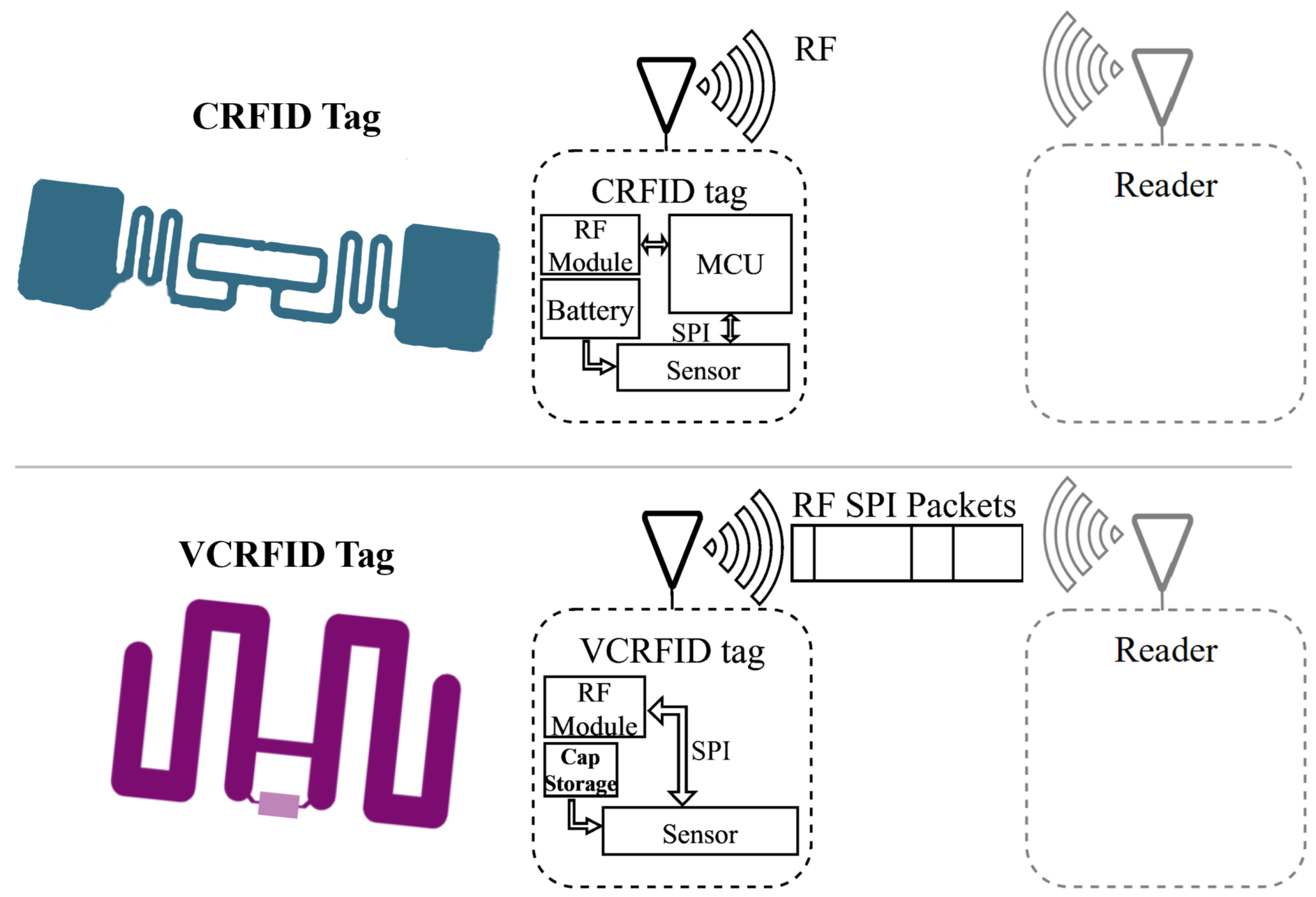
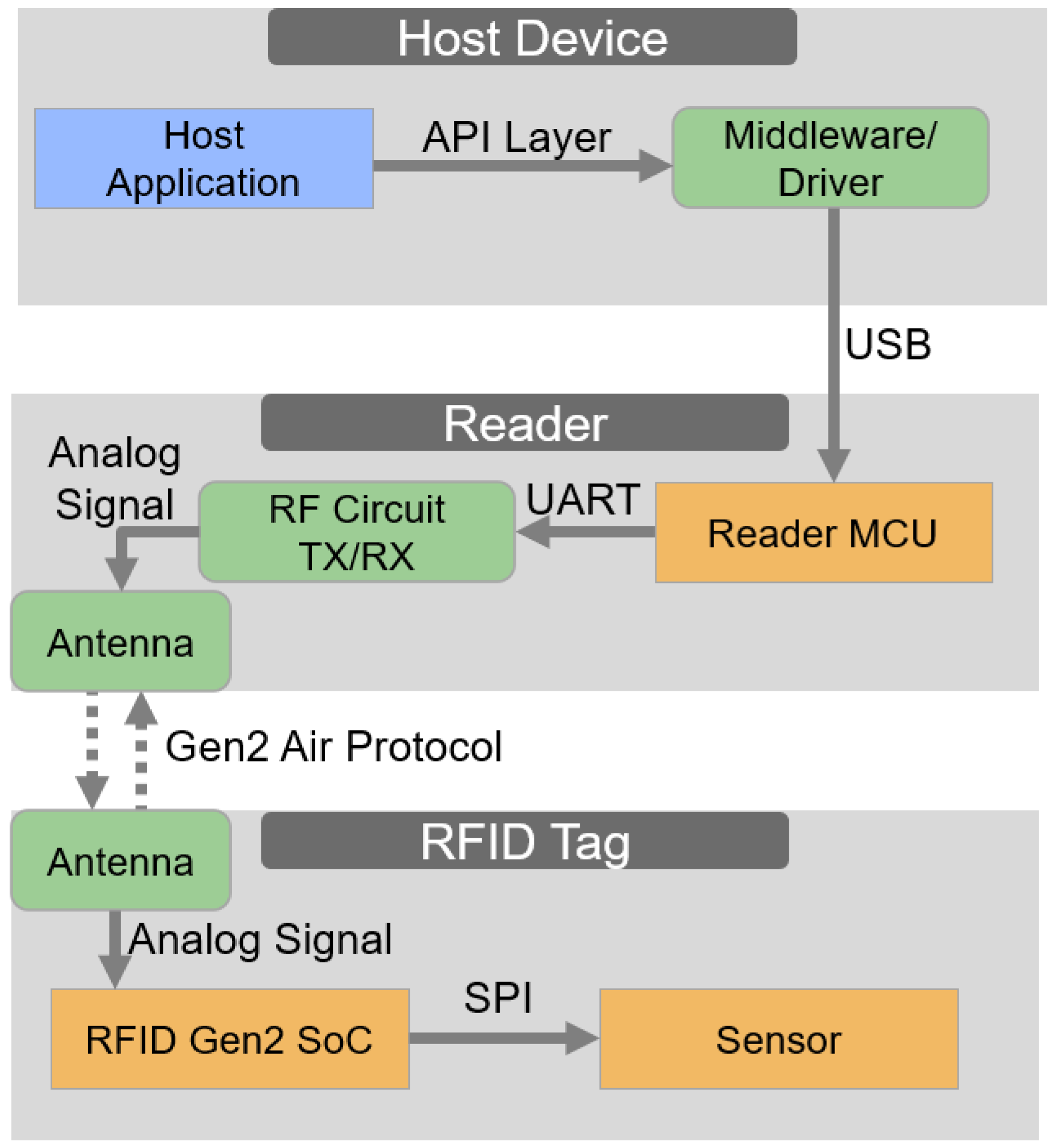
In applications that involve sensors, typically, a controller device, as shown in
Figure 1, is set to handle the operation, stream data, and talk to peripherals through interfaces such as SPI or I
2C. To operate the microcontroller, in addition to requiring additional functionality blocks such as controllers and other peripherals, batteries and the power management block are critical components of the design. However, this design complexity leads to increased demands for processing capability and energy consumption in microcontroller-based devices [
14,
18].
Conventionally, batteries have been the primary energy source to meet these requirements. Still, the major challenges associated with battery-powered IoT devices are that their power is limited and tied to the battery charge, resulting in a finite lifespan and environmental impact.
To address this limitation, RF power harvesting is employed in various wireless sensing platforms [
19,
20,
21,
22]. Using RF energy harvesting enhances device longevity and decreases environmental consequences, promoting sustainable energy use in IoT deployments. It also emphasizes the importance of innovative power management in supporting sensor-based devices.
CRFID tags offer several advantages as IoT devices, but there are some important factors to consider:
Integrating sensors on an RFID tag usually requires the use of a microcontroller or peripheral controller.
A lack of flexibility since reconfigurability of the node, in software or hardware, is not possible without physical access and direct modification to the CRFID tag.
On battery-dependent devices, the overall cost and maintenance, including charging or replacing the battery, is larger compared to that of RF harvesting devices.
Balancing low power requirements and high performance is challenging in sensing CRFID tags due to the microcontroller’s high power consumption.
1.2. Balancing Power Consumption
Various techniques can contribute to reducing power consumption and making the devices more energy-efficient, one of which is duty cycling, periodically turning on and off the devices [
23]. Another is dynamic voltage scaling, a technique to adjust to the consumed power as required [
24]. Notably, standby mode, marked by static leakage power, contributes to substantial energy loss, exacerbating concerns related to short battery lifespans. Finally, another way to extend the device energy lifespan is to design ultra-low power devices [
25]. Ultimately, all previously mentioned energy-saving techniques create trade-offs. The proposed Virtualized Computational RFID (VCRFID) system tag design maximizes harvested RF and decreases the number of elements actively consuming power through the introduction of the concept of a Virtualized Controller for RFID.
2. System Architecture of VCRFID
2.1. Virtualized Controller as Solution
We introduce an approach that focuses on eliminating the high power consumption of microcontrollers and addresses some of the issues associated with CRFIDs as IoT devices. This new system architecture achieves this goal by offering two key features: (1) wireless control of sensors and (2) sensory data computation.
We propose shifting control and computational functions from the tag to the reader. The reader performs the more computationally intensive operations, thus saving energy on the tag and reducing the tag’s power consumption. By eliminating the microcontroller, energy-demanding operations shift to the reader via RF commands. We achieved the virtualization of the microcontroller’s functions using custom SPI instructions sent and received by the reader over RF. In summary, the VCRFID design achieves the following:
Virtualization of the serial peripheral interface bus and controller through custom SPI commands over RF. Offloading power-intensive functions from the tag to the reader eliminates the need for a microcontroller on the tag to control the sensors.
A simplified ultra-low energy design performs efficient energy management for self-power and to power additional sensors on the tag without the need for batteries.
Wireless control and reconfigurability allow new functions to be implemented with a set of SPI instructions sent from the virtualized controller via RF. Thus the configuration and operation of the system are modified on the fly, without requiring physical access to the tag, and quickly adapting the system to changing conditions.
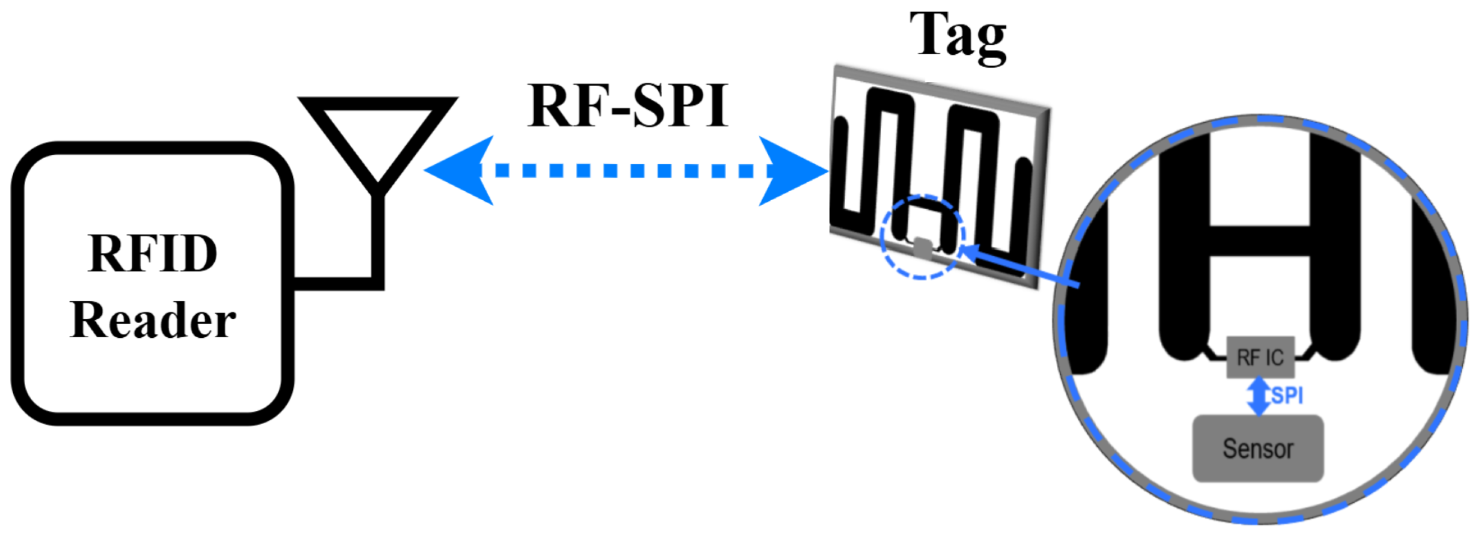
As shown in
Figure 2, we design a sensing system consisting of a tag and a reader node as the main elements. The VCRFID system tag is designed with a receiving antenna, a sensing module, and an RF IC for managing RF communications and long-distance energy harvesting from the transmitted reader signal.
A controller device handles the operation of peripherals, particularly communication between integrated circuits, for example, the sensor and the RF front-end IC, and performs computational tasks. In our design, the VCRFID system employs virtualized instructions to control data transmission and sensor operation and does not require a microcontroller to be built on the tag. The operation is completed using RF instructions transmitted between the sensor and the reader node. These instructions handled by the reader are SPI signals over RF packets, which we can refer to as SPI-over-RF. This eliminates the need for a microcontroller on the VCRFID system tag to manage the sensing functions, as well as removing the need for a battery to provide additional power to the microcontroller.
A detailed comparison presented in
Table 1 evaluates prior CRFID systems and battery-assisted passive RFID tags based on energy consumption per operation, functionality, and system flexibility. The VCRFID system exhibits notable advancements in energy efficiency, operating with a reduced energy budget per transaction compared to WISP and conventional battery-assisted passive RFID tags.
The power required to operate the RFID tag is transmitted by the reader, which emits an RF signal that is received by the antenna on the tag. Once the tag receives this signal, the energy harvesting process in the tag RF IC converts the RF energy into usable electrical energy, which is then used to power the components embedded in the tag. The custom RF commands are transmitted between the reader and the tag’s RF IC, which is directly connected to the sensor.
For the communication exchange between the reader and the VCRFID system tag, the reader sends custom RF command “SendSPI” which contains an SPI packet. The SPI packets are the base for the communication exchange between the reader and the VCRFID tag. As described in
Section 4 [
31], the RF transmission process begins with the reader emitting the SendSPI command over the air using a valid Gen2 frame, which simultaneously powers the tag and delivers the SPI instruction in a single operation. On the tag side, the RF IC (e.g., EM4325) receives and decodes the SPI instruction, functioning as a hardware bridge that transmits the command directly to the sensor via wired SPI lines. The sensor then executes the instruction and, if required, returns data to the RF IC, completing the transaction.
2.2. Vibration Detection
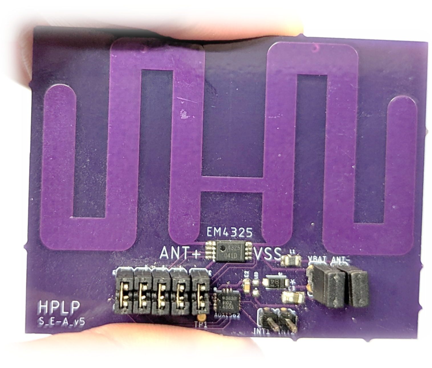
To experimentally validate the main ideas related to the virtualization of the VCRFID functionality, we fabricated a tag prototype on a 4.5 cm × 5.7 cm FR4 board with a receiving meandering dipole antenna and an RF module composed of an EM4325 IC [
27] and sensor module with a 3-axis ADXL362 accelerometer [
33], see
Figure 3. A ST25RU3993-HPEV board from ST Microelectronics was set as the reader node for the VCRFID system.
2.2.1. Experimental Setup
Operation of the tag and all the RF communication is carried out in the UHF band at 915 MHz. Custom SPI commands are sent from the virtualized controller at the reader over RF for reading, writing, and accessing the sensor data in real-time. The testbed included a vibrating platform driven by a controlled fan motor to simulate periodic mechanical motion. The reader used the SendSPI command to trigger real-time SPI reads from the ADXL362 at fixed intervals. Due to the increased energy demand of high-frequency data acquisition, the tag was positioned at 0.5 m from the reader antenna to ensure sufficient RF power delivery. The RF field was maintained at 30 dBm using a directional antenna to focus energy on the tag. Vibration measurements were verified against a reference accelerometer module to ensure data consistency. The data collected through VCRFID was plotted and analyzed to confirm that the passive system could reliably track dynamic motion in three axis.
2.2.2. Results
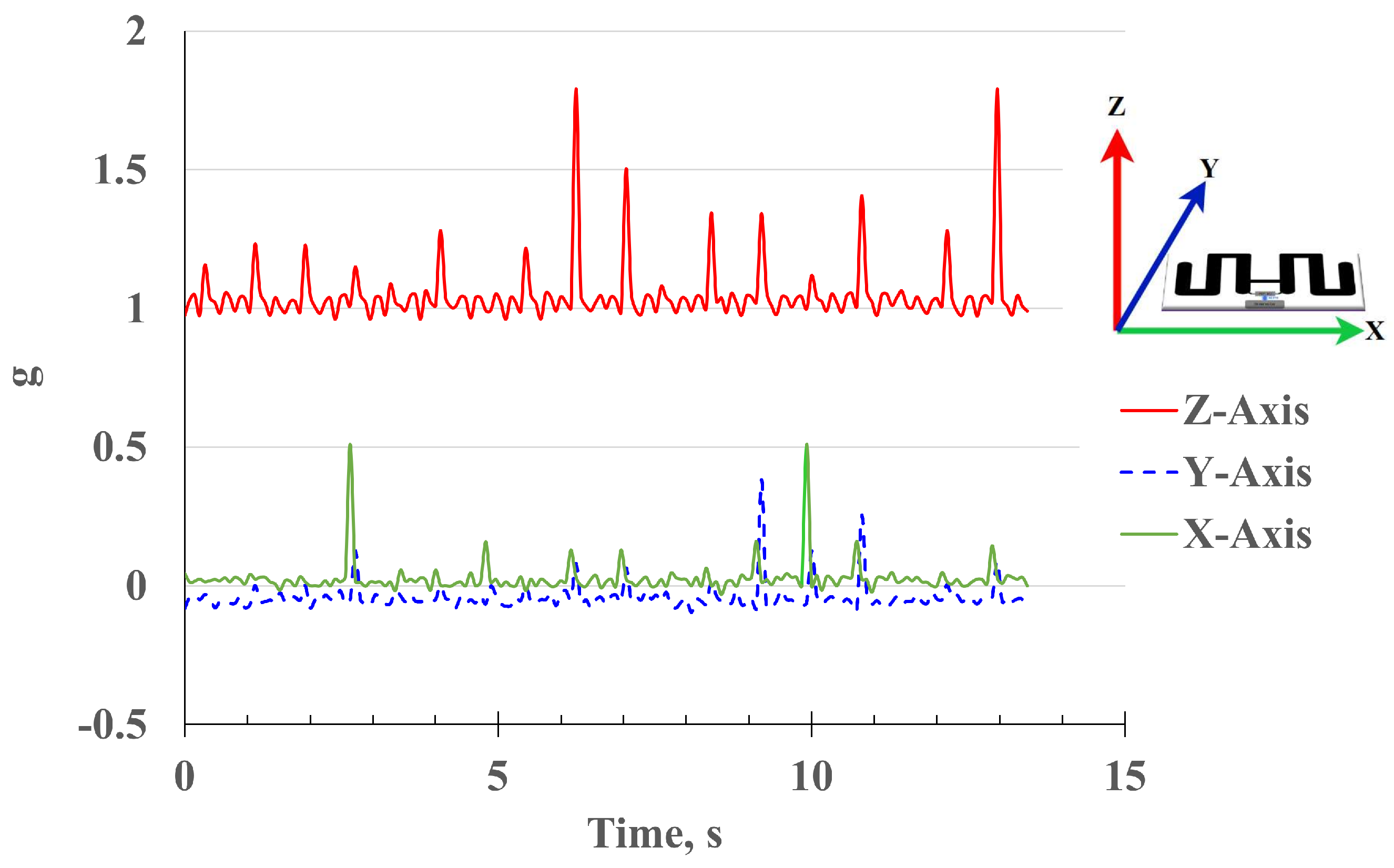
Figure 4 shows vibration data collected wirelessly using the ADXL362 sensor (3-Axis MEMS Accelerometer from Analog Devices, Wilmington, MA, USA) in the VCRFID system tag. The system demonstrated successful SPI communication and sensing with the tags at distances of up to 3 m. However, to ensure packet integrity at the higher frequency required for the vibration test, we positioned the target device 50 cm away from the reader. Using the tag mounted on the device under test, we collect 3-axis acceleration data in real-time, representing the device’s vibration and displacement.
A periodic signal observed in the vibration plot shows a harmonic repeating pattern. The vibration pattern is particularly visible on the Z-axis, representing a movement perpendicular to the surface. The acquired signal can be further analyzed to identify the type of faults in the vibrating equipment based on the patterns observed. With the vibration data acquired through the tag, it’s possible to remotely monitor equipment such as motors, fans, and machines. Because of their simplicity, reliability, and long-life design, VCRFID system tags are ideal for this type of application. These features of the VCRFID device are valuable for numerous applications in remote locations, including anomaly detection, pattern recognition, and predictive maintenance [
34,
35].
3. Edge-Powered WSN Based on VCRFIDs
This section examines the implementation of an edge-powered Wireless Sensor Network (WSN) architecture utilizing ultra-low-power VCRFID tags. The proposed system supports autonomous sensing and data exchange without reliance on physical interconnects or onboard energy storage, enabling scalable deployment in energy-constrained environments. In addition, the architecture is designed to interface with machine learning (ML) frameworks at the edge or in the cloud, allowing for intelligent data processing and anomaly detection. This approach is oriented towards applications with stringent constraints on device size, weight, and power availability, such as aerospace systems, mobile platforms, and remote environmental monitoring.
3.1. Edge Solutions to the Data Deluge
The emergence of trillions of diverse, interconnected sensing devices further accentuates the complexity of wireless network ecosystems. A significant concern arising from the expansion of IoT sensing devices is the overwhelming amount of data, the data deluge [
6]. We may reach a point where our ability to generate analog data surpasses our capacity to efficiently utilize it, potentially impeding the retrieval of valuable information when required. In devices connected to the cloud, we encounter problems such as limited data bandwidth, delays in data transfer to the cloud, higher energy use due to large data handling, and security concerns [
36,
37]. In this evolving landscape of Wireless Sensing Networks (WSN), edge devices have the advantage of being near the information source. However, a drawback associated with edge-based devices is their constraints in computational resources, memory capacity, and power budget [
38,
39]. In addition, a notable challenge is achieving the perfect equilibrium among ease of implementation, affordability, and scalability, all key for IoT connectivity solutions.
3.2. Related Works
Previous research has explored the utilization of RFID tags for wireless sensing applications, specifically employing the Gen2 EM4325 IC developed by EM Microelectronic. The EM4325 is a versatile RFID IC that operates as both a passive and battery-assisted passive RFID IC. The EM4325’s unique capability ensures its robust performance across various applications in an efficient and adaptable mode for RFID technology solutions. The adoption of the VCRFID system facilitates the creation of advanced smart sensing platforms, enhancing data collection and enabling operation in varied and demanding conditions, as demonstrated in the next section.
In the study conducted by [
40], RFID tags incorporating the EM4325 IC were used for epidermal body temperature measurements. Likewise, in the works by [
41,
42,
43], this RF IC is used for temperature measurements, with each study creating new designs for the RFID tag antenna tailored to their specific application. The work by [
31] introduced an ultra-low power virtualized Computational RFID tag system that leverages a virtualized SPI interface over RF to enhance sensing capabilities in EM4325-based tags. Among others, all these works are a brief highlight of the widespread adoption of RFID tags and collectively underscore the widespread adoption of RFID enabled sensors.
For machine learning applications that include RFID tags as sensors, the authors in [
44] developed a Bayesian Regularization classifier ML model that performs structural health monitoring by detecting cracks on conveyor belts. The authors in [
45] developed a classification algorithm based on Support Vector Machines to identify ripe fruits using RFID sensing tags that measure chemicals released by the fruit. However, to our best knowledge, no previous research combines battery-less VCRFID sensing and temperature anomaly detection using LSTM at the edge.
In this work, we implement an edge-powered RFID-based IoT sensor platform to monitor sensor data, such as indoor temperature conditions, and access real-time temperature data.
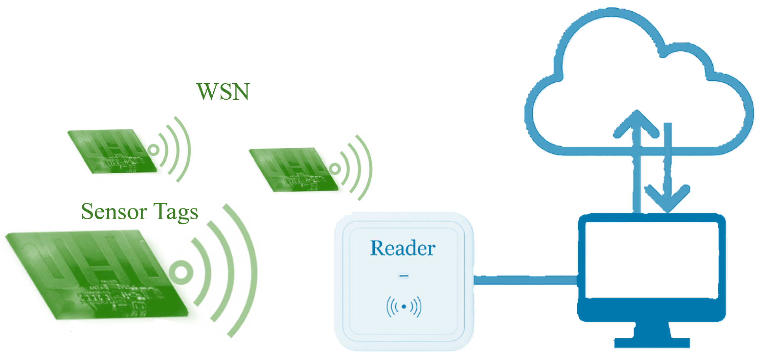
The VCRFID IoT platform provides programmable functionalities and supports a wide array of sensors, including temperature sensors, accelerometers, and other types of Commercial Off-The-Shelf (COTS) SPI-interconnected sensors. The VCRFID-based sensor network is comprised of three main components, as shown in the diagram in
Figure 5. Central to its architecture is a reader connected to an antenna, set for optimal RF data reception and transmission at a frequency of 915 MHz. The reader is connected to a Raspberry Pi that manages the hardware firmware and executes the program to log the sensor data. The sensor network comprises an array of battery-less and wireless IoT sensors, with each sensor embedded within VCRFID tags powered by the transmitted RF signals. We use ultra-low-power VCRFID system tags, first introduced in [
31], for the WSN. The VCRFID system tags offload computationally intensive operations to the reader while harnessing their energy from the RF reader. These tags form the core framework for the network’s sensing functionalities. If the number of sensors needs to be increased, no additional operation is required for the new sensing device to be added to the network. Ready to deploy, all that is required is to bring the RFID-based IoT sensing device within range of a reader.
3.3. RF Power at the Edge
The VCRFID-based IoT platform’s RF harvesting element can mitigate the challenges of power constraints and a limited battery lifetime. The passive VCRFID sensing devices enable self-powered and sustainable battery-less sensor operation. The RFID reader antenna radiates electromagnetic energy that is harvested by the tags and used to power the tag’s IC.
Figure 5 shows a diagram representation of the proposed VCRFID system, consisting of interconnected battery-less and wireless sensing tags in a small form factor that performs the function of a flexible IoT sensing platform. The reader, linked to the antenna, serves as the hub, responsible for sending and receiving RF signals to and from the VCRFID system tags. RF is used for communication and power. The Raspberry Pi serves as an intermediary host between the reader and higher-level systems. These three components establish the foundation of the proposed wireless sensing platform and data acquisition.
3.4. VCRFID Power Evaluation
We can estimate the energy consumed by the EM4325 RF IC during a read of the tag-ID from the measured voltage drop. Each read operation consumes an estimated 400 mV from the capacitor charge. During the duty cycle, after the read operation is completed, the charge is restored with the energy harvested by the EM4325. We can calculate the energy consumed per sensing operation from (
1), where
V,
V, and for a chosen
F. We can estimate
= 52
J.
The energy feasibility condition for a particular sensor can be expressed as:
where the energy required to read the sensor must not exceed the usable stored energy. This expression can be used to calculate the capacitor size and voltage headroom required.
The current consumption for the sensor and RFID tag are and , respectively; C is the capacitance of the storage capacitor, and T is the total time of active operation. The rectified voltage is and is the required operating voltage. Assuming that the sensor has the same voltage supply as the RF IC, V. The left-hand side of the inequality represents the energy consumed by the sensor and the tag during one operation. The right-hand side represents usable stored energy above , the minimum operating voltage of the tag. The equation makes it clear that the limiting factor when selecting sensors is not only the current consumption (which determines power) but also the total required execution time of the sensor and RFID tag (energy rather than power).
Given a transmitted power fixed at 30 dBm for a frequency of 915 MHz, with the transmit antenna gain at 6 dBi, and the receive antenna gain at 2 dBi, we can calculate the received power at various distances using the Friis transmission equation. The effective isotropic radiated power (EIRP) is thus 36 dBm, adhering to the FCC limit for a UHF RFID reader.
The wavelength
is calculated as follows:
Using the Friis transmission equation in dB form:
where
is the received power in dBm, and
r is the range in meters.
We can compare the calculated power consumption of the VCRFID system tag to other battery-less RF harvesting CRFID sensing systems. The tag’s total consumed power will vary depending on the load that’s embedded in it.
The component that has the most significant power consumption is the computational element, the microcontroller, which handles the sensor’s control. The VCRFID system tag’s power consumption comes mainly from the RF IC responsible for RF communication and the attached sensor. Moreover, the tag’s power consumption is considerably lower, indicating a 97% reduction in energy consumption compared to other energy-harvesting RFID tags that incorporate microcontrollers for sensor operation in their circuit.
The VCRFID system’s sensing range during vibration data collection (0.5 m) compared to nominal reads (3 m) reflects the higher energy demands of active sensing (i.e., the ADXL362 accelerometer) during frequent SPI data exchanges. This highlights a key trade-off in passive energy harvesting: as distance increases, the available RF power drops significantly with the distance increments due to the inverse-square law. One way to extend the effective range is by using a directional antenna, which focuses the RF beam and increases received power. However, this comes at the cost of reduced coverage area, making it less suitable for applications requiring wide-area scanning for multiple tags. The RF harvester designs presented in the work by Yin et al. [
21,
22] introduce a promising solution: a UHF RF rectifier with a higher sensitivity and a peak power conversion efficiency of 31.3% . In turn, this approach could enable the VCRFID tag’s system to operate efficiently at lower input voltages, extending reading distances.
The VCRFID system is fully passive, does not store context or maintain operational state across power cycles. Instead, the system operates transactionally:
When the RFID tag receives sufficient RF energy from the reader, it powers up.
Simultaneously, the reader transmits a custom SPI-over-RF instruction, which the tag immediately interprets.
The tag then executes the requested sensing operation on-the-fly, using only the harvested energy.
After completing the operation and transmitting data back to the reader, the tag returns to an idle state. If RF power is lost, the tag simply powers down.
A power interruption (i.e., sudden loss of RF signal) during sensing immediately halts the operation. Any in-progress task, such as sensor activation, SPI transaction, or data transfer, is abruptly terminated. The reader must reissue the SPI-over-RF instruction, and the sensing process restarts. It is up to the reader, or host system, to handle retry logic or detect partial responses.
3.5. WSN Temperature Application
We demonstrate the integration of VCRFID sensor tags as a cost-effective tool for sensing and collecting temperature data. For this, we analyzed the RFID tag’s performance in sensing temperature variation.
We employed the tag’s RF IC EM4325 (EM Microelectronic) for the temperature measurements. The RF IC temperature sensor specifications indicate a typical accuracy of
°C when operating in the range of
°C to
°C [
27].
The sensor data was transmitted to the reader (ST Microelectronic ST25RU3993-HPEV) at the US 915 MHz operating frequency. The battery-less, ultra-low power VCRFID sensing devices’ design allows for configuration flexibility, which means the sensing devices can be reconfigured to support various types of SPI-controlled sensors using a virtualized SPI interface as described in [
31]. Similar to the temperature sensor example in this paper, the system can be set to obtain humidity, vibration, acceleration, and position if desired sensor is connected via SPI to the tag. The use of the VCRFID system sensing tags enables temperature monitoring applications in locations with restricted access and power constraints where physical access is difficult. In the described VCRFID-based edge computing system, processing and data storage occur within the reader and Raspberry Pi host device near the data source. This approach allows for data pre-processing, decreasing the amount of data intended for transfer to the cloud. Consequently, it efficiently mitigates the expenses associated with data transmission and accumulation within the cloud infrastructure.
3.6. Temperature Data Analysis
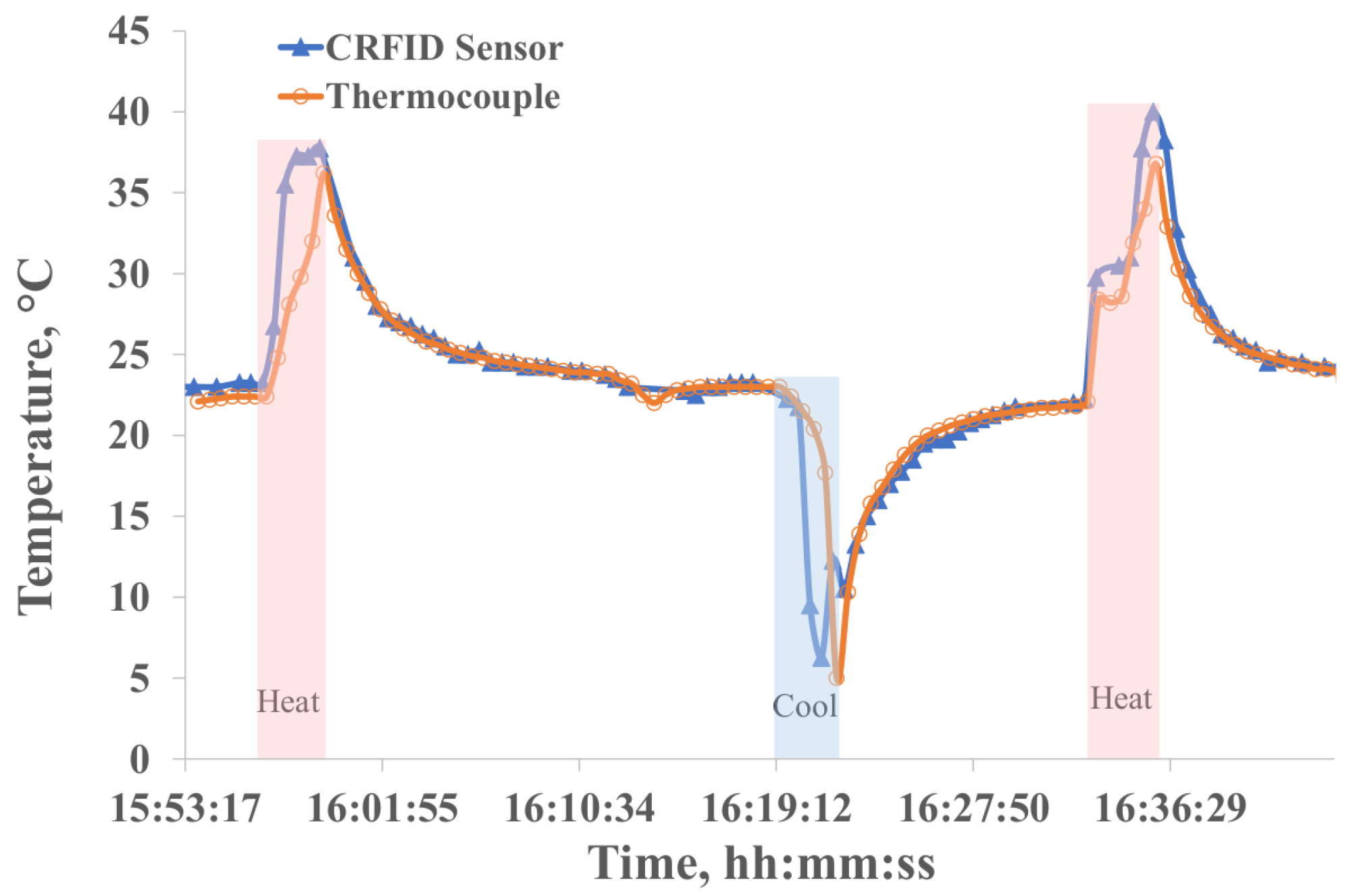
This section analyzes the temperature sensing capabilities of the VCRFID system tags, evaluating the potential of the system to gather and relay temperature data at regular intervals. For the experiment, a sensing tag was exposed to sudden temperature fluctuations, alternating between periods of heating and cooling. The temperature readings obtained from the VCRFID system tag were collected and compared against the temperature measurements concurrently recorded using a thermocouple (Elitech Tlog-100). This process allowed us to gauge the accuracy and reliability of the sensing tags in capturing temperature data under varying conditions.
Figure 6 shows the temperature data collected and monitored using a single VCRFID IoT system tag of the sensor network every 30 s. The sensing tag was exposed to heat and cold. Temperature data were collected every T = 30 s using the tag’s EM4325 IC and compared to the temperature recorded with a thermocouple.
To find the accuracy of the tag measurements, we compare the data points from both the tag and the thermocouple for the same time intervals. To calculate the difference between the two readings at each time interval, then average these differences to obtain the measurement mean error. This mean error can then be expressed as a percentage of the total range of temperatures recorded. Although some variation is observed between the thermocouple and VCRFID data collected, particularly at sudden rises and falls in temperature, the measurement’s accuracy between both sensing elements is consistent. This suggests that the WSN, with its VCRFID system sensing tags used for real-time temperature monitoring in various applications, can reliably replicate traditional sensing methods while offering the advantages of wireless connectivity and remote monitoring capabilities without the battery limitation.
3.7. Temperature Anomaly Detection
In this section, we analyze the temperature data acquired from a VCRFID WSN. The system uses an LSTM autoencoder model for anomaly detection in temperature variations. We configured the Raspberry Pi to oversee the anomaly detection model, manage the reader, and aggregate the sensor data. We run an optimized lightweight LSTM autoencoder model with the help of TensorFlow as the backend on the Raspberry Pi.
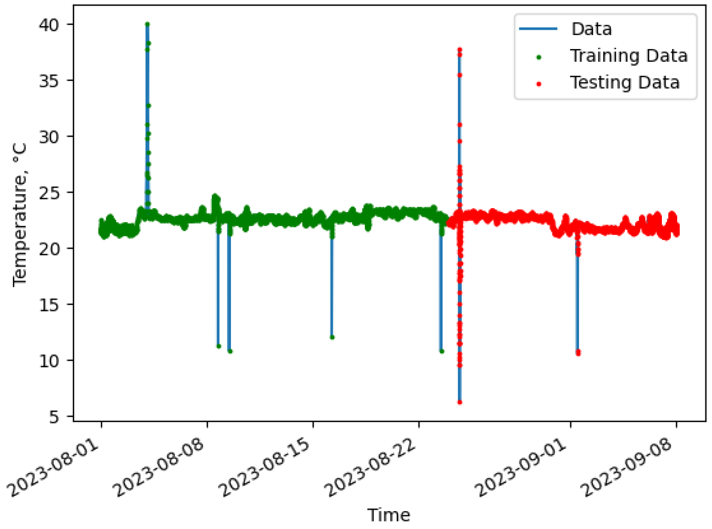
The data used in this work, shown in
Figure 7, was collected for over a month from a WSN consisting of three tags in the VCRFID system that measure the room temperature every half hour using an EM4325 RF IC and transmit that data at 915 MHz via RF to the reader. The resulting plots show the capabilities of VCRFID system tags as IoT devices in a WSN and serve as an example of an anomaly detection system powered by the edge.
As shown in
Figure 7, the sensor data was partitioned into subsets: 70% allocated for training and the remaining 20% part designated for testing. The model training is then validated with 10% of the data allocated for validation purposes.
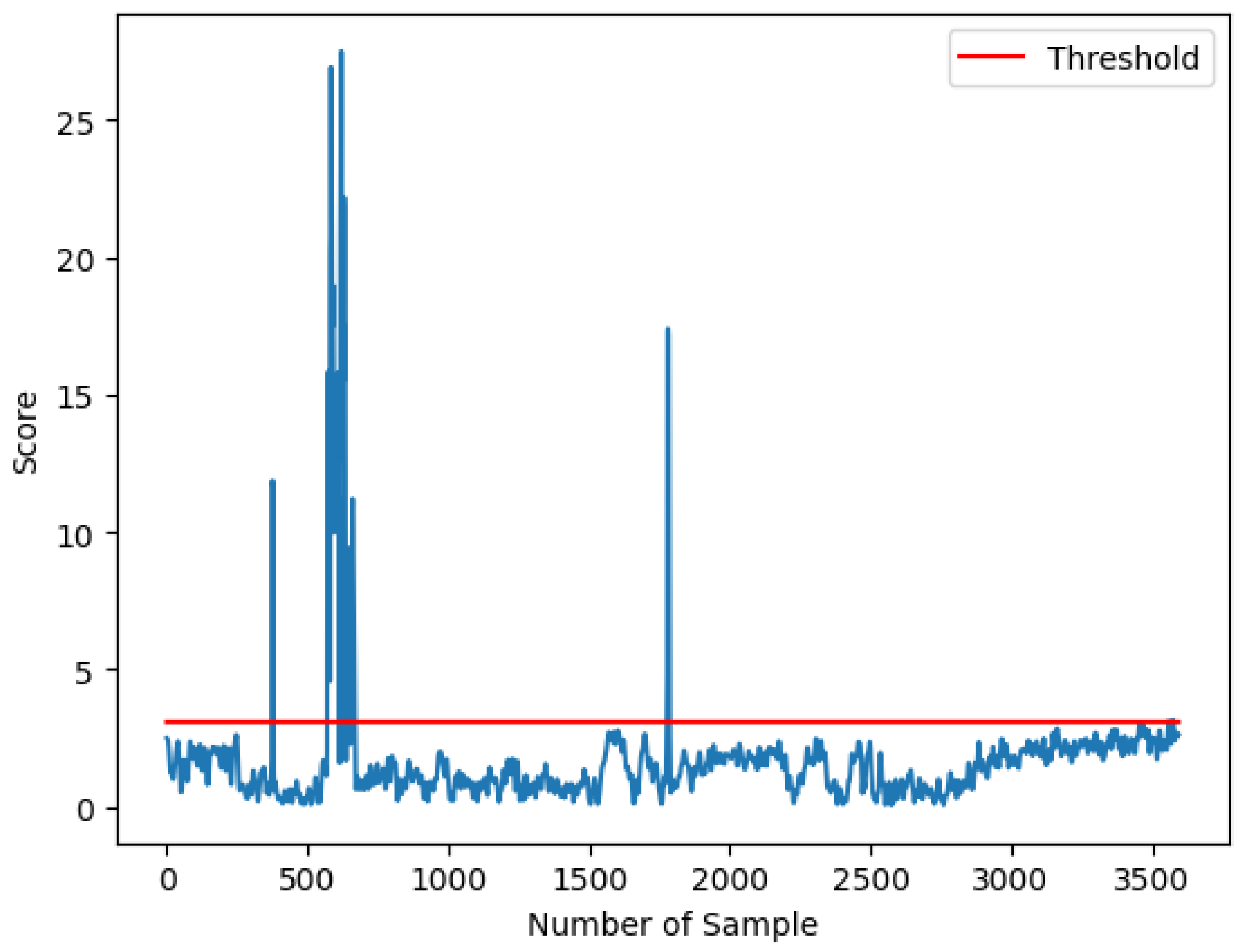
As defined by Chandola et al., an anomaly is a pattern in data that does not conform to a definition of normal behavior [
46]. The primary output from the LSTM autoencoder model is the reconstruction error observed in
Figure 8, which measures how well the model can reconstruct the input data. Considering the standard deviation
of the temperature data’s normal distribution, we established the threshold value and validated the results through event observation. Data points exceeding
, for a threshold ratio over 0.95% of the samples, are identified as outliers. Reconstruction errors with high values indicate anomalies, while values within the threshold limits are regarded as normal. We determine which data points are considered anomalies and which are considered normal based on the reconstruction scores and threshold.
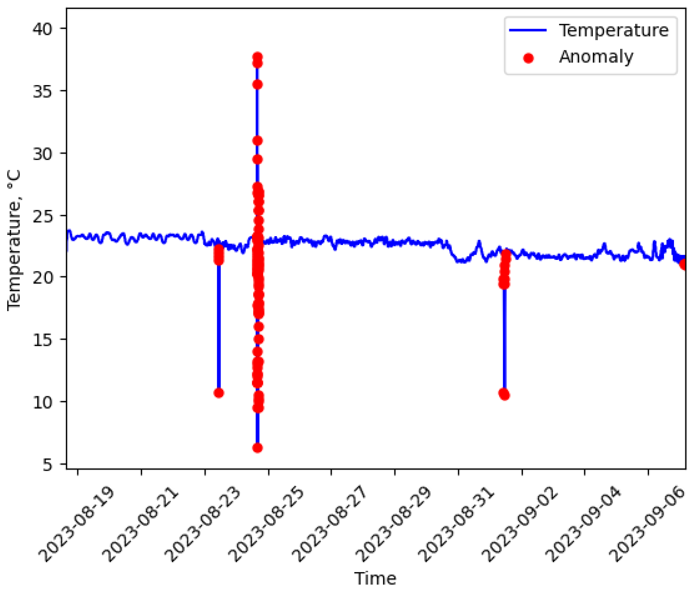
3.8. Temperature Anomalies Detected
Data points indicating anomalies provide insights into patterns of temperature variation and the predictive capability of the LSTM autoencoder model. The detected anomaly data points, as illustrated in
Figure 9, represent the temperature anomalies detected. The temperature anomalies detected, highlighted in red, are plotted over the temperature data gathered by the sensors shown in blue. To understand the performance of the LSTM autoencoder model during training, we analyze the training loss and validation loss, which suggests that the model will respond well to new data that the model has not seen during training. A larger dataset would likely enhance the model’s performance.
The anomaly detection was implemented using an LSTM autoencoder and integrated at the edge. The efficient transmission of data is crucial. Under estimations that each data sample occupies 1 byte, with an associated energy cost of 0.01 mJ per byte for transmission, the total energy requirement to transmit all 3595 samples (comprising 3415 normal and 179 anomalies) is approximately 35.94 mJ. If only the 179 anomalous samples detected with the LSTM algorithm are transmitted, the energy consumption significantly drops to about 1.79 mJ, thereby achieving a substantial reduction in data transmitted by approximately 95.02%. With the operations performed near the sensors, this reduces latency, avoids delays in real-time detection, and reduces power from processing and transmitting large amounts of raw data to the cloud.
3.9. ML in Edge-Powered VCRFID
A key feature of the VCRFID architecture is the integration of machine learning algorithms directly at the reader, leveraging edge intelligence to process and interpret sensor data from multiple tags in real time. For example, vibration and temperature data collected from battery-less tags deployed on pumps and motors in Industry 4.0 environments can be used by the reader to perform predictive maintenance using embedded ML models, identifying early signs of mechanical failure without relying on cloud connectivity or local processing on the tags themselves. This approach is exemplified by the LSTM-based predictive analytics method discussed in the previous section by [
32], which operates entirely at the reader and demonstrates how sequence-learning models at the edge represent a state-of-the-art technique for RFID-based IoT sensor networks. To address the trade-offs between model complexity, tag energy consumption, data accuracy, and real-time responsiveness in edge-based machine learning, we propose the following guidelines for model selection. First the implementation of lightweight, low-latency models (e.g., LSTM, 1D CNNs, or decision trees) that are optimized for edge deployment. Second, to analyze the power consumption, latency, and accuracy profiles across various model configurations and sensor types to identify optimal operating points.
Recurrent neural networks (RNNs), particularly Long Short-Term Memory (LSTM) models, have been effectively applied to RFID sensor data for sequential prediction tasks. For instance, Oguntala et al. [
47] employed an LSTM-RNN to classify human activities based on passive RFID Received Signal Strength (RSS) sequences, achieving an accuracy of 98.18%. Their LSTM model outperformed traditional classifiers such as random forests, hidden Markov models (HMM), Naive Bayes, and hidden semi-Markov models (HSMM), as well as a convolutional neural network (CNN) baseline. It is important to note that in this context, accuracy refers to the proportion of correctly predicted activity labels, and the authors also report metrics such as precision, recall, and F1-score.
More broadly, performance in RFID-based ML systems is typically reported as classification accuracy (%) or regression error (e.g., mean squared error (MSE), root mean squared error (RMSE), or percentage error). For example, the aforementioned LSTM-based human activity recognition (HAR) system achieved 98.18% accuracy [
48], while DeepTag, a hybrid CNN/LSTM architecture, reported approximately 94% accuracy in tag classification tasks [
49]. In regression-based tasks, such as tag ID prediction, errors are often reported using RMSE; for example, one study reports an RMSE of just 0.87% [
50].
These examples highlight the importance of performance metrics and consistent performance evaluation when deploying ML models in RFID-based systems. Real-time applications demand low latency (typically <100 ms) and high throughput, which are key performance indicators. Notably, edge-based machine learning systems typically offer significantly lower latency than their cloud-based counterparts. Once parameters, such as accuracy, error rate, latency, and throughput, are properly defined and consistently measured, they can serve as a standardized framework for evaluating and benchmarking the performance of different ML models across various RFID-based deployments. This enables informed model selection based on specific application requirements, resource constraints, and performance trade-offs.
4. VCRFID Tools for IoT Applications
Together with the hardware of the VCRFID system tags, the development of an application and firmware was carried out to wirelessly program and send the instructions that control the operations of the RF IC and sensors. The VCRFID system’s SPI-over-RF approach employs custom commands within the EPC Gen2 standard to facilitate communication with EM4325 chips. While the EPC Gen2 standard natively supports the use of custom commands, not all readers are equipped to handle them by default. Implementing such commands requires firmware updates or modifications, which may not be feasible for all devices. The EM4325 chip supports SPI communication and can be configured via custom commands. However, utilizing this feature requires both the tag and the reader to support and correctly interpret these custom commands, necessitating coordinated firmware capabilities on both ends. This methodology is consistent with prior efforts that have utilized EPC Gen2 extensibility for specialized applications.
For the tags to interact with the reader hardware, the development software was required to handle the high-level commands and the firmware to convert them into low-level instructions that the reader board could understand. This application fulfills wirelessly and dynamically through the RF channel the configuring functions that, for example, other CRFID devices complete before deployment through a 4-wire programmer on the MSP430 to control access to the sensor. Analyzing the capabilities of typical RFID systems, we first encounter that the commercial reader technology, predominantly designed for warehouse inventory management, is constrained to three basic functions: select, inventory, and access [
28]. This last function, access, allows the user to read and write words from a specific register in the memory bank of the RFID IC. Therefore, recognizing the limitations of such a restricted functionality, we developed our own application, leveraging cutting-edge STMicroelectronics reader technology together with the EPC Gen2 protocol, to introduce a versatile solution tailored to meet the evolving needs of IoT and Industry 4.0.
4.1. Host and Reader
We pair the operation of a host computer and reader to handle the implementation of the EPC Gen2 standard for the UHF passive RFID system. The EPC Gen2 (v3) protocol offers features with commands for direct tag instruction, such as controlling the SPI bus that connects the sensors, broadening the scope of possible applications. EPC Gen2 is an air interface protocol defined by EPCglobal identified as the standard for UHF passive RFID (RAIN RFID) [
51]. Part of the Gen2 protocol’s focus is on enhancing the RFID system’s security and overall performance in tune with Industry 4.0.
The VCRFID system, as previously introduced in
Section 2.1 and
Section 3, enables wireless identification and sensing using the VCRFID system tags hardware.
Based on the initial setup described, the system consists of three main components: the host, the reader (also known as an interrogator), and the RFID tag. These three elements interface together through the Rust code ecosystem, the program used for developing the software components of the VCRFID system. The following section contains a detailed description of each component and the operation of the VCRFID system.
As shown in
Figure 10, the host computer interfaces with the ST25RU3993 reader hardware through a dedicated software and firmware layer, which translates high-level commands into low-level instructions that the reader board can understand. This allows users to concentrate on developing application logic that incorporates the RF operations. The host computer manages key functionalities, including configuration management, sensor data processing, integration of ML processing, and network communication, which are detailed as follows:
Configuration Management: The host computer is used to handle the ST25RU3993 RF reader board’s configuration, such as RF power, modulation, and data rate, to optimize the system for various operational environments and tag types.
Data Processing: Once the RF reader board receives data from RFID tags, it is relayed to the host computer that processes this information, performing actions such as data logging, analysis, and ML processing, triggering external systems.
Network Communication: The host computer often serves as a gateway, enabling the RFID system to communicate with other systems and databases over a network and setting up the protocol for message transmission, which supports uses like real-time monitoring.
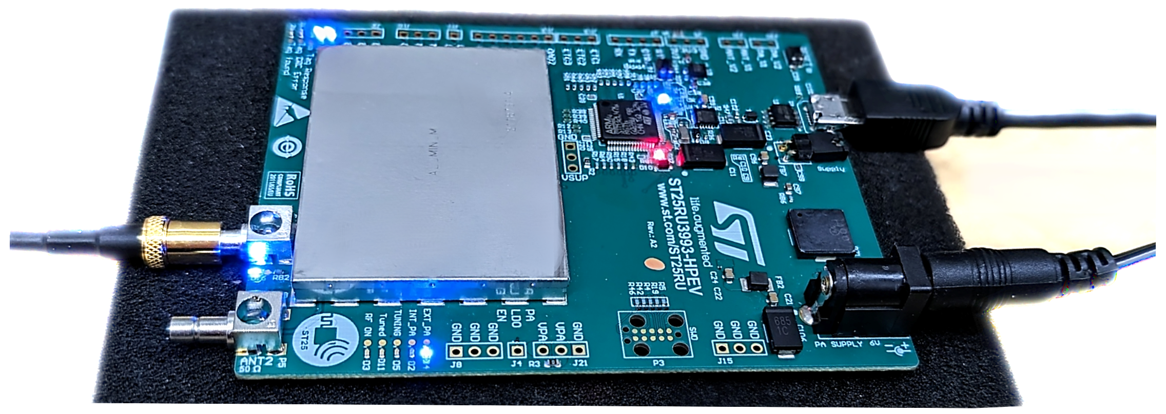
4.1.1. Reader Hardware
The reader hardware consists of the ST25RU3993 RAIN (UHF) from STMicroelectronics with an STM32L476RGT6 (Arm® 32-bit Cortex®-M4) Microcontroller Unit (MCU) and a UHF RFID reader IC ST25RU3993 for high-performance execution of UHF RFID reading and writing functions. The reader has a tunable radio frequency from 840 to 960 MHz that can operate in continuous wave mode or modulated RF output and is controlled by a host device via a USB/UART bridge.
Figure 11 shows the ST25RU3993 RAIN (UHF) board with the mentioned controlling circuit, power connections, one for the external power amplifier (PA) and micro-B USB connector for communication and power from the host computer, and two RF ports, ANT1 and ANT2, for antenna connection.
4.1.2. Reader Firmware
We developed a firmware to handle the control of the reader system and communicate with the RFID tags. This firmware handles the SPI and other custom commands through various crates and libraries, which include sensor libraries (adxl363) and a generic ST RFID library (libstuhfl). The app, in a RUST suite, covers a broad range of functionality, from basic sensor checks to configuration of the RFID IC and ADXL, demonstrating a thorough approach to validating tag interactions and sensor operations. The firmware code is available in the HPLP group repository.
4.1.3. Reading and Writing to the Tag RFID SoC Memory
In order to read and write to the RFID SoC memory addresses, the RFID SoC has to be set to a specific reading mode to access the memory data. The configuration process involves writing to designated memory addresses within the user bank of the IC memory. For example, subsequent to the writing operation using the em_write_config test function, a verification read operation, em_read_config, can be conducted on the memory address to ensure the integrity of the data written and that the configuration of the tag IC was successful.
The memory of the RFID SoC is subdivided into four memory banks, as shown in
Table 2, with each of these memory banks structured into 64 pages, with each page containing 4 words that are each 16 bits in length. The first memory bank, defined as Reserved, contains the chip’s Kill and Access passwords. The TID memory bank, containing the IC serial number that serves as the tag ID, is factory-configured and unmodifiable. The bits of UII/EPC encoding in commercial RFID tags serve as storage for the Unique Identifier for the tagged object. The user memory is allocated to the system memory configuration. Additionally, the user memory bank contains the words for passive and BAP mode configuration, as well as the I/O control words for the SPI enable mode, including interface configuration.
Some of the main test functions for the tag SoC are:
continuous_power: Controls the reader on/off of continuous power for the specified time. Supplies the tag RF power without interrogation.
find_tags: Detect and identify tags within its range through a broadcast query for EPC ID.
em_passive_mode: Configures the device’s functionality in passive mode, utilizing internal power for operation without external sources like batteries.
em_bap_mode: Configures the device’s Battery Assisted Passive (BAP) mode for enhanced tag operation.
em_sensor_test: Requests and retrieves the data of the temperature sensor integrated into the EM4325 device.
4.1.4. Reading Sensor Data
Once the tag device is configured as an SPI Master and SPI operation is enabled, the system reader can be used to send custom SendSPI commands to access sensor data. This approach enables the real-time acquisition of acceleration data for the interaction, for example, between the EM4325 chip and the ADXL363 accelerometer sensor. Nevertheless, as previously mentioned, this method requires the support of user-defined Gen2 commands by the RFID reader. A list of the operations enabled through the application functions, listed as serial Rust tests, is shown in
Table 3, and the main functions are described next.
Functions for the ADXL accelerometer sensor:
adxl_setup_config This function sets the configurability of the ADXL device for optimal sensor performance.
adxl_sensor_test Activates the functionality of the ADXL’s sensors. Returns three axis acceleration data.
adxl_sensor_duration Activates the functionality of the ADXL’s sensors for a time specified. The ADXL sensor operates acceleration functions for a specific duration.
4.2. VCRFID from Edge to Cloud Implementation
For RFID-enhanced automated monitoring, we created a Python 3.10 script that establishes the connection to a message queuing telemetry transport (MQTT) broker through a client application, reads RFID tag data from a reader or a series of readers, and then publishes the data to a specified MQTT topic. The database repository is connected to Grafana, an open-source platform for monitoring, visualization, and data analysis. It’s designed to work with a specific RFID reader and MQTT broker configuration. MQTT is a network protocol that provides machine-to-machine publish-and-subscribe messaging. It was selected as the network protocol based on its lightweight implementation and bandwidth-efficient characteristics.
4.2.1. Automated Monitoring Features
Among the Features that the automated monitoring and reporting system integration performs are the following
Read tag data from an external reader using a sub-process for Rust Test.
Uses regular expressions to extract relevant information, metadata from the reader output.
Handles MQTT connection and credentials from host and publishing of data.
Connects to an MQTT broker to publish RFID tag data.
4.2.2. Security in VCRFID
The VCRFID system inherits and extends security features from the EPCglobal Class-1 Gen2 RFID standard, which provides foundational protection mechanisms widely adopted in commercial RFID systems [
52]. These include standard RFID tag security mechanisms as:
Password Protection: EPC Gen2 tags support two types of 32-bit access passwords:
Access Password: Controls access to tag memory and enables or disables tag functionality.
Kill Password: Permanently disables the tag if security is compromised.
Lock Commands: Allow the reader to lock individual memory banks (EPC, TID, or User memory), preventing unauthorized overwriting.
Challenge-Response Authentication (in newer standards like Gen2v2): Some tags include support for symmetric authentication protocols to verify legitimate readers.
In addition to standard RFID protections, VCRFID explores enhanced security mechanisms tailored for ultra-low-power systems. Recent work on VCRFID has proposed architectural solutions that enable cryptographic operations within the severe energy constraints of passive RFID tags. For example, Gao et al. [
53] propose an approach that strengthens hardware-based security by combining a Weak Physically Unclonable Function (PUF) with a lightweight cryptographic core, offering a robust and energy-efficient foundation for secure authentication in CRFID platforms. This hybrid construction results in a Strong PUF that is lightweight and Energy-Efficient. This design is also suitable for low-power environments, such as CRFID and IoT edge nodes. Because of that, CryptoPUF can be integrated into constrained systems without significant energy or area overhead and is resistant to Machine Learning (ML) attacks.
5. Conclusions and Future Work
The Internet of Things (IoT) integrates everyday physical objects into a smart, interconnected network. This digital cyber-physical revolution, driven by the demand for connectivity and information, has been accelerated by wireless devices enabling remote communication, control, monitoring, and automation. As we navigate the challenges of power delivery and data management in the vast and multifaceted IoT landscape, the role of RFID becomes increasingly significant, especially in the context of Industry 4.0.
This paper presents a unique approach to wireless sensing IoT devices through computational RFID technology, combining RFID capabilities with advanced computational and sensing technology. We have proposed and put into operation a system that employs a Virtualized Controller for Computational RFID-based IoT Sensors [
31] and the use of power at the edge to enable the smart sensing and computational capabilities of the VCRFID system [
32]. We have used the VCRFID system as a Wireless Sensor Network (WSN) with edge data processing based on an LSTM autoencoder in the host device (raspberry Pi) that minimizes transmission costs to the cloud. The next improvements should focus on continuing the exploration, incorporating VCRFIDs and ML at the edge, and refining data preprocessing for ML analysis.
Our work is driven by the potential of smart sensing devices based on RFID technology and the tangible benefits they can bring. Known for its low cost, simplicity, and efficiency, the VCRFID sensor system offers practical solutions to predict industrial equipment failures using real-time data and historical machine behavior analysis. By simplifying the implementation and deployment of computational RFID systems for equipment monitoring and predictive maintenance, we can significantly reduce downtime and maintenance costs, thereby contributing to the advancement of smarter, more connected factories.
To quantify the impact and implications of our research in Computational RFID, we focus on the following points:
Cost Reduction: Through a more straightforward design that eliminates the need for microcontrollers embedded on the tag circuit to manage the sensors, we estimate a notable cost reduction of approximately $10 USD per Computational RFID tag. Additionally, the VCRFID system completely removes the need for ongoing device maintenance associated with battery replacements.
Energy Consumption Reduction: With the implementation of the VCRFID sensing system, we observe a 97% energy consumption reduction compared to computational tags with MCUs. In addition, we see improvements in data transmission efficiency by 95% by only transmitting anomalies detected using the ML method.
Adoption Rate: By comparing the current number of users of RFID systems across various industries, we can anticipate a significant uptake of the new VCRFID technology. VCRFID is an attractive IoT option driven by the ease of implementation of the sensing devices, lower costs per device, and enhanced self-power capabilities.
Future directions of research will focus on further improving the range of VCRFID systems, enhancing their security features, expanding the scope from single-reader/single-tag to networked multi-reader/multi-tag systems, and especially developing full applications deploying VCRFID systems for medical applications, Industry 4.0, smart agriculture, etc.


