Abstract
In this paper, we study an unmanned aerial vehicle (UAV)-enabled maritime communication system, where a single rotary-wing UAV is dispatched to communicate with multiple moving vessel users. We formulate the energy efficiency optimization problem with a propulsion energy consumption model by jointly considering the UAV transmit power, flight trajectory, and flight velocity. The problem is a non-convex fractional programming problem, which makes it difficult to obtain the optimal solution. To solve this problem, we propose an efficient algorithm utilizing the successive convex approximation techniques and Dinkelbach (SCAD) algorithm. In particular, we divide the original problem into three involved sub-problems that can be solved by adopting alternate optimization. In order to satisfy the constraint of maximum UAV flight velocity, we obtain a modified flight trajectory by matching the UAV positions. Numerical results demonstrate the effectiveness of the proposed scheme which effectively improves the energy efficiency for UAV communication. Meanwhile, the SCAD shows an outstanding performance in terms of energy efficiency for a long-duration flight.
1. Introduction
The proposed sixth generation mobile communication network technology allows air, space, ground, and sea communications to be linked together as a whole, achieving ubiquitous coverage for global users [1]. In recent years, with the rapid development of maritime activities, the requirement for maritime communication systems has increased dramatically. Currently, the main maritime communication includes satellite communication and on-shore base stations. Although satellite communication can provide wide coverage, it also inevitably suffers from shortcomings involving high costs, limited bandwidth, and many delays. On the other hand, the limited coverage of on-shore base stations leads to coverage blind areas [2]. In this instance, unmanned aerial vehicles (UAVs) are widely used as a mobile base station in the maritime environment owing to their flexibility and low cost [3].
Although UAVs can be used in maritime communications thanks to their flexibility, UAV communication still faces various challenges. The issue of insufficient onboard energy severely limits the communication performance and flight duration of UAVs [4]. To address this challenge, researchers have conducted studies on energy-efficient UAV communication. A fixed-wing UAV-based communication system was considered in [5] to maximize energy efficiency by optimizing UAV flight trajectory and transmit power. The impact of wind velocity on fixed-wing UAV trajectories and energy consumption was considered in [6]. The authors in [7] introduced a circular flight trajectory based on a propulsion energy model for fixed-wing UAV, and jointly optimized the velocity of the UAV and trajectory radius to maximize energy efficiency. In contrast to [7], the authors in [8] derived a propulsion energy model for rotary-wing UAV and proposed a path discretization method to reduce UAV energy consumption. Based on the energy model in [8], the authors in [9] incorporated the concept of thrust-to-weight ratio into the propulsion energy model, resulting in further optimization of energy efficiency. The authors in [10] considered the use of reconfigurable intelligent surface (RIS) to assist the UAV communication system in case of direct link interruption to jointly optimize the UAV position, the RIS phase-shift matrix, and the transmit power of users to improve the system energy efficiency.
To further improve the communication efficiency of UAVs, several studies have considered the UAV channel model. Considering the mobility of UAVs and ground receivers, a three-dimensional multiple input and multiple output (MIMO) channel model for air-to-ground communication was proposed in [11]. In order to enhance the communication quality, a reconfigurable intelligent surface was introduced in [12] to passively reflect signals between the transceivers. In [13], an arbitrary-elevation two-cylinder model was introduced to characterize the UAV-to-UAV Rician fading channels, which captures the arbitrary altitude and vertical movement of the UAV. Based on the elliptic cylinder model proposed in [14], the statistical properties of the proposed UAV–MIMO channel model were investigated in [15]. It is worth mentioning that only non-line-of-sight (NLoS) propagation was considered in [15] due to the obstruction of buildings and trees.
However, the above studies essentially consider UAV-to-ground communication. Unlike the conventional terrestrial communication networks, the maritime UAV-to-ship communication has several unique channel characteristics such as sparsity, sea wave fluctuation, and the waveguide effect caused by changes in atmospheric pressure and air temperature [16]. Wang et al. [17] established a novel multi-mobility UAV channel model which considered these channel characteristics. On the other hand, compared with terrestrial base stations that cannot obtain user location information in a timely manner [18], maritime vessels generally follow fixed shipping lanes, which allows us to estimate the shipping lane information in future periods [19]. We can fully exploit the specific characteristics of ship user mobility for the study of resource allocation. [20] studied the deployment strategy and path planning problem of multi-UAV-assisted maritime communication systems, assuming that the UAVs charge on the ship and then set off sequentially to communicate with the users, and proposed a positive cosine optimization algorithm to minimize the UAV flight energy consumption. [21] comprehensively considered the possible energy insufficiency problems of UAVs and maritime users, used UAVs to transmit energy signals to charge the users, and minimized the system energy consumption by jointly optimizing the UAV flight trajectory and communication time, which effectively improved the system energy efficiency. [22] considered the joint optimization of the phase shift coefficient, amplitude coefficient, and RIS ratio of the RIS-assisted UAV communication system under the constraints of the interference noise and the communication quality of users to maximize the system energy efficiency. Moreover, in order to improve the serving efficiency and guarantee the service quality for each user, it is essential to deploy UAV communicates with multiple users [23].
In this paper, we focus on energy efficiency optimization with a rotary-wing UAV deployed to communicate with multiple vessel users in the maritime environment. Despite the differences between land and sea communication scenarios, optimization algorithms for land communication can be applied to sea communication scenarios. Considering the mobility and sparsity of vessel users in UAV maritime communication, we aim to maximize the energy efficiency of the UAV by jointly optimizing the transmit power, flight trajectory, and flight velocity of the UAV, taking into account the communication throughput and propulsion energy consumption.
2. System Model and Problem Formulation
2.1. System Model
We consider a UAV-aided maritime communication system as shown in Figure 1. Specifically, a rotary-wing UAV flies at a fixed altitude H to communicate with N ship users on the sea, which the user set is denoted by . Let T denote the entire UAV service time and divide it into M time slots with sufficiently small length, defined as , and each time slot length is . The n-th user coordinate at the m-th time slot is denoted as . The position of the UAV at the m-th time slot is given by . We assume that the maximum velocity of the UAV is . The position change of the UAV during flight satisfies the following constraint:
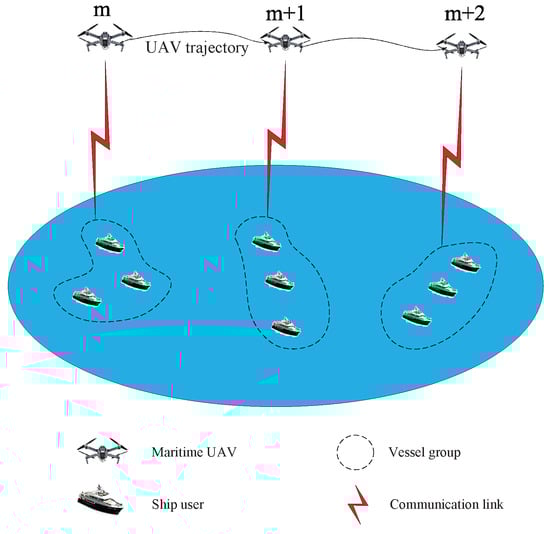
Figure 1.
UAV-aided maritime communication system model.
The UAV trajectory during entire time T is defined as . Hence, the distance between the UAV and the n-th user at the m-th time slot can be obtained as
Since the obstacles are rarely presented over the sea, we assume that the communication links are dominated by line-of-sight (LoS) link. The communication link follows the free-space path loss model, which can be expressed as
where represents the path loss at the unit reference distance. The achievable rate for the n-th user at the m-th time slot can be obtained as
where B denotes the channel bandwidth, is the transmit power of the UAV serving the n-th user at the m-th time slot, and is the noise power spectral density at the receiver. Thus, the sum achievable rate for the UAV in the entire duration can be obtained as
2.2. UAV Propulsion Energy Consumption Model
For a rotary-wing UAV, energy consumption mainly consists of communication-related energy and propulsion energy. Since the communication energy is much less than the propulsion energy in practical applications, it is neglected in this paper. Propulsion energy ensures the flight state of the UAV at high altitudes and provides reliable maneuverability for the UAV. In general, the propulsion energy depends on the flight velocity and acceleration. In this paper, the additional energy consumption caused by UAV acceleration is ignored for analysis simplicity. According to the expression in [9], we obtain the propulsion energy model with respect to (w.r.t.) the velocity at the m-th time slot as
where
Here and represent the blade profile power and the induced power in hovering status, respectively, denotes the parasite power of UAV, where denotes the tip velocity of the rotor blade, and denotes the mean rotor induced velocity in hover. In addition, denotes the fuselage drag ratio, s denotes the rotor solidity, and A denote air density and rotor disc area.
2.3. Problem Formulation
Based on the aforementioned system model, we aim to maximize the energy efficiency of a UAV-aided maritime communication system by jointly optimizing UAV transmit power, UAV flight trajectory and the velocity of the UAV. The maximum transmit power of the UAV is defined as , then the optimization problem can be formulated as
where constraints (C1) and (C2) indicate that the UAV allocates transmit power for each user without exceeding the maximum transmit power, and (C3) limits the flight velocity of the UAV.
3. SCAD Algorithm
To address the complicated problem (P1), this section presents an efficient algorithm based on the successive convex approximation (SCA) technique and the Dinkelbach algorithm. The optimization scheme separates the original problem into three sub-problems to be solved. First, we optimize the transmit power and the UAV positions, followed by matching the UAV positions to obtain a modified UAV flight trajectory. Subsequently, we convert the expression of the propulsion energy model into a convex form, which proceeds to tackle problem (P1).
3.1. Resource Allocation Optimization
Note that the numerator and denominator of problem (P1) are coupled because exists in both of them. In this sub-section, we give an initial value of UAV position to consider the throughput and sum propulsion energy separately. Moreover, when the UAV position is given, the optimization problem can be further decoupled in any time slot. Therefore, we consider a single rotary-wing UAV communicates with all the ship users at an arbitrary time slot. Then the optimization problem can be expressed as
Problem (P2) is a non-convex problem related to transmit power and UAV positions. We introduce an auxiliary variable which is defined as the sum throughput at each time slot; thus, the new problem can be written as
Here, constraint (C1) is actually a quality of service (QoS) for users. Problem (P3) remains a non-convex problem. Due to the non-linear coupling between the UAV positions and the transmit power in the expression of , and need to be separated and alternately optimized to obtain the optimal solution. We plan to first determine the UAV initial positions and optimize the transmit power and then substitute the optimized transmit power into the objective function to optimize the UAV communication positions.
In this paper, we consider the centroid position of all ship users at the m-th time slot as the cluster center, and define the cluster center as .
We use as the initial position of the UAV at the m-th time slot, and the problem (P3) can be rewritten as
Problem (P4) is a standard convex optimization problem that can be solved directly with a certain optimization algorithm to find the optimal transmit power .
3.2. UAV Trajectory Optimization
In this sub-section, we substitute the optimal transmit power into problem (P3) to optimize the UAV communication location, which is denoted as
where
Considering the left-hand side of the above constraint, it is still non-convex w.r.t. . If is considered as a whole part, we can perform a first-order Taylor expansion at any given local point to obtain an approximate lower bound that satisfies convex constraint. The new lower bound of is shown in expression (14). Actually, equivalently denotes the QoS for each user.
By replacing the constraint, the new optimization problem can be expressed as
Problem (P6) is a standard convex optimization problem. We can obtain the optimal transmit power and communication positions of the UAV at the m-th time slot by optimizing problems (P4) and (P6) alternately until the objective function converges.
Furthermore, the optimal trajectory of the UAV should satisfy the constraint of the maximum flight velocity mentioned in (1). For the trajectory that does not satisfy the requirement, we need to repeat the optimization steps in the previous sub-section to find the optimal trajectory of the UAV. Accordingly, an algorithm for UAV resource allocation and trajectory optimization is given as shown in Algorithm 1.
| Algorithm 1 Resource allocation and trajectory optimization algorithm |
|
3.3. UAV Energy Efficiency Optimization
As the square root part of expression (6) is non-convex, in problem (P1) is also non-convex. Hence, we first introduce the slack variable , which satisfies
then we easily obtain the expression as
For any given Taylor expansion local point , the right-hand side of (17) can be lower-bounded via the first-order Taylor expansion. The convex constraint can be expressed as
According to the above derived approximate lower bound functions, problem (P1) can be reformulated as
Problem (P7) is a quasi-convex optimization problem, containing linear numerator and convex denominator, and all constraints are convex. The problem can be solved by the Dinkelbach algorithm. Dinkelbach algorithm is widely used to solve the fractional programming problem, the fundamental idea of this algorithm is to transform the fractional programming problem into a linear programming problem by introducing auxiliary variables, and the algorithm gradually approaches the optimal solution by gradually optimizing and updating the auxiliary variables. Here, a fractional programming problem such as is converted to , and is a constant. We utilize the Drinkelbach algorithm to compute the optimal solutions of and and set the energy efficiency incremental threshold to maximize the energy efficiency by iteratively updating until its convergence. The algorithm is summarized in Algorithm 2.
| Algorithm 2 Dinkelbach algorithm for energy efficiency maximization |
|
4. Numerical Results
This section provides numerical results to validate the effectiveness of SCAD algorithm. The UAV altitude is set as H = 100 m and the channel bandwidth is assumed to be B = 2 MHz. For the UAV propulsion energy consumption model, the parameters are used if not mentioned otherwise: = 79.8 w, = 88.6 w, = 120 m/s, = 4.03 m/s, = 0.6, s = 0.05, A = 0.503 and = 1.22 [8,9]. We assume that there are eight piers equally spaced on a circular sea boundary with a radius of 800 m and a fixed shipping lane between each two piers. A total of 28 users randomly move in a straight line between two piers with no greater than 20 m/s and turn around when they reach the piers. Figure 2 shows the trajectories of the 28 users with given in T = 50 s.
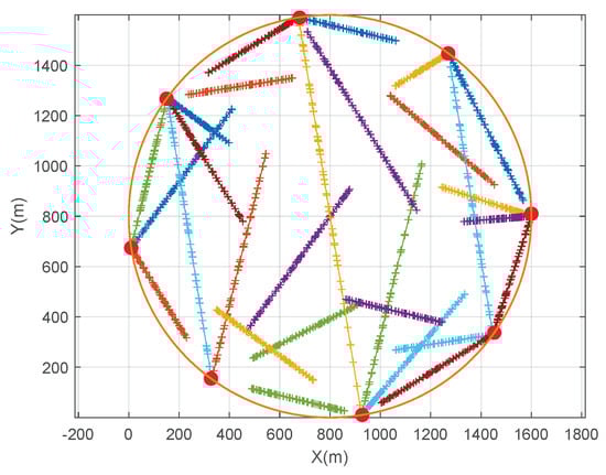
Figure 2.
Trajectories of 28 users.
To clearly show the flying route of UAVs with SCAD, we randomly choose three ship users at any three time slots in Figure 3. Different spot shapes denote different time slots.
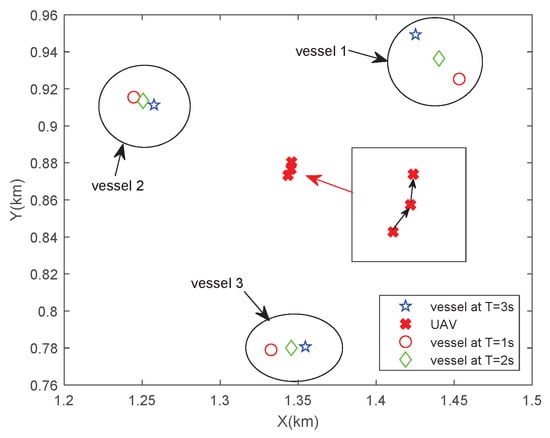
Figure 3.
UAV flight trajectory following the cluster center.
In Figure 3, we consider the multiple users and the mobility of the vessels, which is effective for UAVs to fly following the cluster center, instead of just flying directly above each user as described in [9]. Apparently, our approach is more applicable to the maritime communication environment because there are plenty of ship users in a busy harbor. It effectively avoids the additional energy consumption of visiting each user and reduces time for UAV communication.
We also compare the SCAD algorithm with two other path algorithms. One of the trajectories involves the UAV flying around a circle with a radius of 400 m, which is denoted as circular trajectory (CT) [6]. Another trajectory is inspired by [23] that the UAV flies along the centroid positions of all ship users at each time slot, which is denoted as cluster center hovering (CCH).
Figure 4 presents the comparison between the SCAD algorithm and CCH scheme on the trajectories of UAV. From the figure, it can be seen that the cluster centers are only distributed in a small area, forcing the UAV to continuously fly with frequent sharp turns. This flying ensures that the UAV maintains a stable speed in a small area, but it exacerbates the propulsion energy consumption of the UAV. On the other hand, the optimized UAV trajectory is much smoother and guarantees higher communication rates.
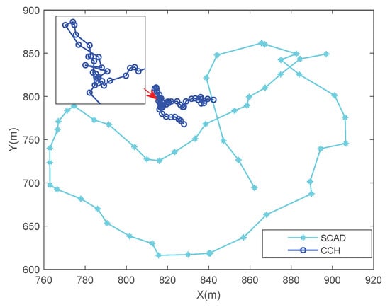
Figure 4.
Comparison of two different trajectories of the UAV.
In Figure 5, we analyze the effect of flight altitude on the communication rate. The communication throughput of the UAV clearly increases with the transmit power. Note that, as the flight altitude increases, the free-space path loss also increases, resulting in weaker channel conditions. Therefore, the optimal coverage performance is achieved at a UAV altitude of 100 m, which complies with the FAA regulation that restricts UAV flight altitude within 122 m.
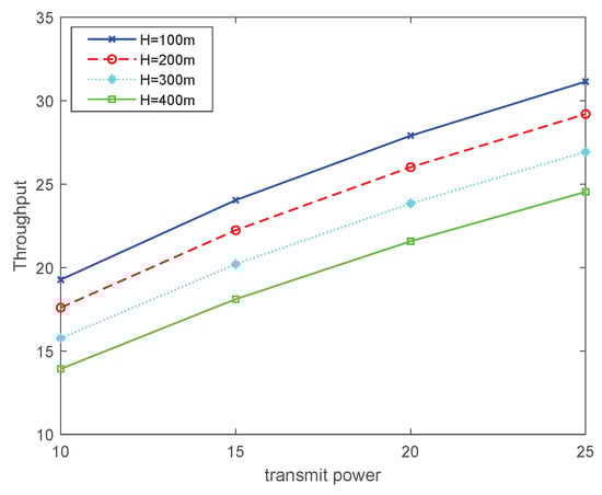
Figure 5.
Throughput with different flight altitudes.
Figure 6 shows the simulation results of the energy efficiency of the UAV for three different trajectory schemes in different T. The energy efficiency obtained by our proposed SCAD algorithm gains higher value than others. On the other hand, the UAV flying following CT is constrained by the limited position, resulting in relatively low service quality and low energy efficiency. Furthermore, as the flight duration increases, the advantages of our proposed SCAD algorithm become more apparent, with a more obvious performance gain in energy efficiency. Thus, the SCAD algorithm can be more applied to long-duration flights.
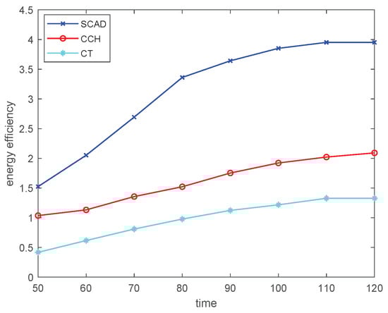
Figure 6.
Energy efficiency comparison of three different trajectory plans.
Figure 7 demonstrates the variation of energy efficiency with increasing transmit power for three different trajectory schemes of UAV. It can be observed that, as the transmit power increases, the energy efficiency gradually improves. Our proposed optimization algorithm yields a more obvious improvement in energy efficiency. Due to positional constraints, the energy efficiency improvement is relatively slow for CT when increasing transmit power.
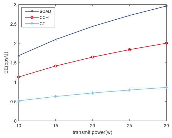
Figure 7.
Comparison of energy efficiency with increasing transmit power.
5. Conclusions
This paper investigates a maritime communication system enabled by rotary-wing UAVs. We focus on maximizing the energy efficiency of the UAV subject to the UAV velocity constraint. By proposing the SCAD algorithm, we jointly optimize the velocity, flight position, and transmit power of the UAV to obtain the modified UAV flight trajectory, which enhances the energy efficiency while satisfying the QoS for users. Simulation results show that the UAV flight trajectory obtained using the proposed algorithm is smoother than the other trajectory schemes, and higher energy efficiency is obtained.
Author Contributions
Conceptualization, Y.X. and P.S.; Methodology, J.Z.; Writing—original draft, W.Z.; Writing—review and editing, Y.X. All authors have read and agreed to the published version of the manuscript.
Funding
This research was supported in part by the free exploration research fund of Jiangsu Key Laboratory of Power Transmission and Distribution Equipment Technology, Hohai University, under Grant 2023JSSPD09, in part by the National Natural Science Foundation of China under Grant 62476080, in part by Key Laboratory about Maritime Intelligent Network Information Technology of the Ministry of Education under Grant EKLMIC202405, and in part by Changzhou Sci & Tech Program under Grant CJ20241033.
Data Availability Statement
Data will be made available on request.
Conflicts of Interest
The authors declare no conflicts of interest.
References
- Wang, J.B.; Zeng, C.; Ding, C.F.; Zhang, H. Unmanned Surface Vessel Assisted Maritime Wireless Communication Toward 6G: Opportunities and Challenges. IEEE Wirel. Commun. 2022, 29, 72–79. [Google Scholar] [CrossRef]
- Warrier, A.; Aljaburi, L.; Whitworth, H. Future 6G Communications Powering Vertical Handover in Non-Terrestrial Networks. IEEE Access 2024, 12, 33016–33034. [Google Scholar] [CrossRef]
- Erdelj, M.; Natalizio, E. Help from the Sky: Leveraging UAVs for Disaster Management. IEEE Pervas. Comput. 2017, 16, 24–32. [Google Scholar] [CrossRef]
- Zeng, Y.; Zhang, R.; Lim, T.J. Wireless communications with unmanned aerial vehicles: Opportunities and challenges. IEEE Commun. Mag. 2016, 54, 36–42. [Google Scholar] [CrossRef]
- Guo, L.L.; Ji, X.D.; Zhang, S.B. Energy-efficient full-duplex UAV relaying with trajectory optimization and power control in maritime communication environments. China Commun. 2022, 19, 216–231. [Google Scholar] [CrossRef]
- Zhang, Y.F.; Lyu, J.B.; Fu, L.Q. Energy-Efficient Trajectory Design for UAV-Aided Maritime Data Collection in Wind. IEEE Trans. Wirel. Commun. 2022, 21, 10871–10886. [Google Scholar] [CrossRef]
- Zeng, Y.; Zhang, R. Energy-Efficient UAV Communication With Trajectory Optimization. IEEE Trans. Wirel. Commun. 2017, 16, 3747–3760. [Google Scholar] [CrossRef]
- Zeng, Y.; Zhang, R.; Xu, J. Energy Minimization for Wireless Communication With Rotary-Wing UAV. IEEE Trans. Wirel. Commun. 2019, 18, 2329–2345. [Google Scholar] [CrossRef]
- Duo, B.; Dai, X.H.; Yuan, X.J. Energy-Efficient UAV Communications: A Generalized Propulsion Energy Consumption Model. IEEE Wirel. Commun. Lett. 2022, 11, 2150–2154. [Google Scholar]
- Wen, Z.; Na, Z.; Zhang, Y. Energy Efficiency Optimization for RIS-Assisted Uplink-NOMA UAV Network. IEEE Wirel. Commun. Lett. 2024, 13, 1640–1644. [Google Scholar] [CrossRef]
- Jiang, H.; Zhang, J.F.; Zhang, Z.C. A Novel 3D UAV Channel Model for A2G Communication Environments Using AoD and AoA Estimation Algorithms. IEEE Trans. Commun. 2020, 68, 7232–7246. [Google Scholar] [CrossRef]
- Xiong, B.P.; Jiang, H.; Zhang, Z.C. A 3D Non-Stationary MIMO Channel Model for Reconfigurable Intelligent Surface Auxiliary UAV-to-Ground mmWave Communications. IEEE Trans. Wirel. Commun. 2022, 21, 5658–5672. [Google Scholar] [CrossRef]
- Liao, X.W.; Jiang, H.; Xiong, B.P. Three-Dimensional UAV-to-UAV Channels: Modeling, Simulation, and Capacity Analysis. IEEE IoT J. 2023, 11, 10054–10068. [Google Scholar]
- Jiang, H.; Zhou, J.; Mukherjee, M. Channel Modeling and Characteristics for 6G Wireless Communications. IEEE Netw. 2021, 35, 296–303. [Google Scholar] [CrossRef]
- Jiang, H.; Wu, L.; Dang, J. Three-Dimensional Geometry-Based UAV-MIMO Channel Modeling for A2G Communication Environments. IEEE Commun. Lett. 2018, 22, 1438–1441. [Google Scholar] [CrossRef]
- Akhtar, M.W.; Saeed, N. UAVs-Enabled Maritime Communications: UAVs-Enabled Maritime Communications: Opportunities and Challenges. IEEE Syst. Man. Cybern. Mag. 2023, 9, 2–8. [Google Scholar] [CrossRef]
- Liu, Y.; Wang, C.X.; Chang, H.T. A Novel Non-Stationary 6G UAV Channel Model for Maritime Communications. IEEE J. Sel. Area. Comm. 2021, 39, 2992–3005. [Google Scholar] [CrossRef]
- Wei, C.; Liu, H.P.; Zhang, Z.C.; Wu, L. Approximate Message Passing-Based Joint User Activity and Data Detection for NOMA. IEEE Commun. Lett. 2017, 21, 640–643. [Google Scholar] [CrossRef]
- Wei, T.; Feng, W.; Wang, J.; Ge, N. Exploiting the Shipping Lane Information for Energy-Efficient Maritime Communications. IEEE Trans. Veh. Tech. 2019, 68, 7204–7208. [Google Scholar] [CrossRef]
- Zheng, C.; Liu, J.M.; Chi, K. Seamless and Energy-Efficient Maritime Coverage in Rechargeable UAV Networks. In Proceedings of the 2024 IEEE International Conference on Unmanned Systems (ICUS), Nanjing, China, 18–20 October 2024. [Google Scholar]
- Jing, T.; Jiao, H.Y.; Gao, Q.H. Energy-Minimization Trajectory Optimization with Dynamic NOMA Clustering and Wireless Powering for UAV-Assisted Maritime Communication. In Proceedings of the 2023 15th International Conference on Communication Software and Networks (ICCSN), Shenyang, China, 21–23 July 2023. [Google Scholar]
- Lin, K.; Yang, H.; Zheng, M. Penalized Reinforcement Learning-Based Energy-Efficient UAV-RIS Assisted Maritime Uplink Communications Against Jammingt. IEEE Trans. Veh. Tech. 2024, 73, 15768–15773. [Google Scholar] [CrossRef]
- Tang, R.; Feng, W.; Ge, N. NOMA-based UAV communications for maritime coverage enhancement. China Commun. 2021, 18, 230–243. [Google Scholar] [CrossRef]
Disclaimer/Publisher’s Note: The statements, opinions and data contained in all publications are solely those of the individual author(s) and contributor(s) and not of MDPI and/or the editor(s). MDPI and/or the editor(s) disclaim responsibility for any injury to people or property resulting from any ideas, methods, instructions or products referred to in the content. |
© 2025 by the authors. Licensee MDPI, Basel, Switzerland. This article is an open access article distributed under the terms and conditions of the Creative Commons Attribution (CC BY) license (https://creativecommons.org/licenses/by/4.0/).