Abstract
The article describes an Arduino-based, portable, remotely usable weather monitoring station capable of measuring temperature, relative humidity, pressure, and carbon monoxide (CO) concentration and transmitting the collected data to the Cloud through the mobile telephony network. The main modules of the station are as follows: a DHT11 sensor for temperature and relative humidity sensing, a BMP180 sensor for pressure monitoring (with temperature compensation), a MQ7 sensor for the monitoring of the CO concentration, an Arduino Uno board, a GSM SIM900 module, and a buzzer, which is activated when the temperature exceeds 35 °C. The station operates as follows: the Arduino Uno board gathers the data collected by the sensors and, by means of the GSM SIM900 module, it transmits the data to the Cloud by using the mobile telephony network as well as the ThingSpeak software which is an open-code IoT application that, among others, enables saving and recovering of sensing and monitoring data. The main novelty of this work is the combined use of the GSM network and the Cloud which enhances the portability and usability of the proposed system and enables remote collection of data in a straightforward way. Additional merits of the system are the easiness and the low cost of its development (owing to the easily available, low-cost hardware combined with an open-code software) as well as its modularity and scalability which allows its customization depending on specific application it is intended for. The system could be used for real-time, remote monitoring of essential environmental parameters in spaces such as farms, warehouses, rooms etc.
1. Introduction
Climate and weather conditions have a serious effect on almost every human activity and weather monitoring and forecast are among the most important operations of everyday life. In that respect, the monitoring and collection of weather data is essential, yet it usually requires sophisticated and expensive equipment which is not easily available.
During the recent years, several attempts have been made to develop weather monitoring systems that are portable and affordable. Most of those systems use an Arduino module which is an open-source microcontroller (MC) that can be easily programmed and reprogrammed. The Arduino platform was introduced in 2005 as a low-cost, easy way for the development of devices that can interact with their environment through actuators and sensors. Arduino is also capable of exchanging information over the Internet. The hardware that Arduino uses is known as the Arduino development board while the software for the code development is the Arduino Integrated Development Environment (IDE). Built up with an 8-bit or 32-bit Atmel microcontroller, Arduino can be easily programmed by using variants of the C or C++ language in the Arduino IDE [1]. A detailed literature review regarding Arduino boards and fields of applications as well as a description of the steps and research questions related to prototyping with Arduino (that were applied during this work) is included in [2].
A conceptual diagram of a microcontroller-based weather monitoring system is shown in Figure 1. Proper sensors collect data regarding environmental parameters (such as temperature, relative humidity and barometric pressure) and feed a microcontroller while the transmission of the collected data is implemented by means of a communication module.
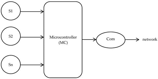
Figure 1.
A conceptual diagram for a typical weather monitoring system (S1, S2,…, Sn: sensors, Com: communication module).
In [3], a weather monitoring system is presented which uses an ATmega-328 microcontroller (the one used in Arduino-Uno boards) programmed with Python and capable of sensing temperature, barometric pressure and luminocity and transmitting collected data through the GSM network (with the use of the Internet mentioned as a future possibility). Ref. [4] describes a system based on an ARM microcontroller that can monitor temperature and relative humidity and transmit data by means of an RF (2.4 GHz) module. The same parameters are monitored by the system described in [5], which uses an Arduino-Uno microcontroller and transmits data to a base-station by using a Zigbee wireless link. Ref. [6] presents an Arduino-Uno-based system that monitors temperature, relative humidity, barometric pressure and wind speed and transmits data also by means of Zigbee. In [7], an Arduino-Uno-based arrangement is described which monitors temperature, relative humidity, and luminosity, but collects data only locally. Ref. [8] presents a compact Arduino-Uno-based weather monitoring station which uses Bluetooth for the transmission of data, while [9] presents a weather monitoring prototype which senses temperature, barometric pressure, and luminosity and transmits data through WiFi. The same parameters are monitoring by the system described in [10] which, uses an Arduino-mega microcontroller and transmits the collected data to a smartphone via Bluetooth. Ref. [11] in turn proposes a hardware module, also based on Arduino-Uno, which, apart from temperature, pressure, and relative humidity, can also monitor wind speed and direction and transmit collected data to a computer through a Zigbee wireless link. Ref. [12] describes a system capable of monitoring temperature, luminosity, and CO concentration that uses an Arduino-Uno board and ZigBee to transmit data to the Internet, ref. [13] presents an Arduino-Uno-based system for sensing temperature, relative humidity and wind-related parameters that uses WiFi for data transmission while [14] presents a system that uses an ESP8266 microcontroller, senses temperature, relative humidity, and CO concentration and transmits data by means of WiFi and the Internet of Things (IoT). Ref. [15] proposes a weather monitoring system which uses Arduino-Uno as the main controller and is capable of transmitting weather data by using an RF 2.4 GHz module, while [16] proposes an Arduino-Mega-based system that uses a single sensor for temperature, relative humidity and pressure monitoring and employs WiFi for data transmission. Finally, ref. [17] presents a system that can monitor temperature, relative humidity and pressure and either display data on an LCD screen or transmit them to a computer or a mobile device for further analysis.
All in all, most of the presented weather monitoring systems (especially the most recent ones) are based on some Arduino-based microcontroller (often, the Arduino-Uno version) and monitor environmental parameters such as temperature, relative humidity, barometric pressure, and luminosity. An overview of the systems mentioned above is shown in Table 1.

Table 1.
An overview of weather monitoring systems.
The present article describes an Arduino-based, portable, and remotely usable weather monitoring station that can monitor essential environmental parameters, such as temperature (T), relative humidity (RH), barometric pressure (P), and the carbon-monoxide (CO) concentration. The main modules of the station are a DHT11 sensor for temperature and relative humidity sensing, a BMP180 sensor for pressure monitoring (with temperature compensation), and a MQ7 sensor for the monitoring of the CO concentration, an Arduino-Uno board (for gathering the sensors’ data), a GSM SIM900 module (for the transmission of data), and a buzzer, which is activated when the temperature exceeds 35 °C. The novelty of the described system is the combined employment of the widely available mobile telephony (GSM) network (by means of the ThingSpeak open-code), the Cloud, and IoT for the transmission of the remote collection of the gathered data that enhances the portability and usability of the system. The merits of the proposed system are its capability of monitoring essential environmental parameters, the easiness and the low cost of its development (owing to the use of easily available and low-cost hardware in combination with open-code software), its enhanced usability and portability (due to the use of the GSM network) as well as its modularity and scalability given that sensors can be added or removed at will.
2. Description of the System
The modules included in the weather monitoring system (also cited in Section 1 above) are shown in Table 2:
Table 2.
The modules of the weather monitoring system.
2.1. The DHT11 Sensor
DHT11 (Figure 2) is a digital temperature and humidity sensor that uses a negative-temperature-coefficient (NTC) thermistor to monitor the ambient air temperature and a resistive-type component to measure the relative humidity [18].
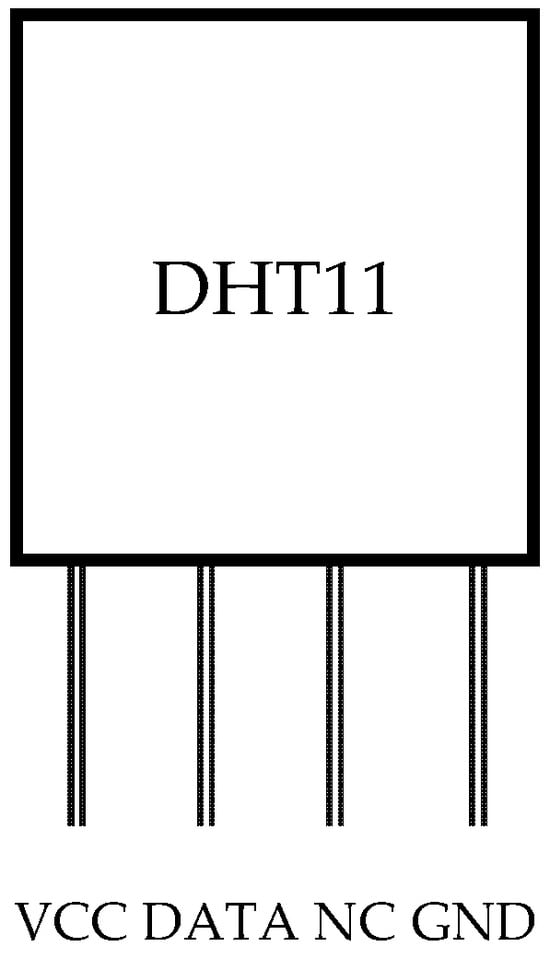
Figure 2.
A schematic of the DHT11 sensor.
In a first-order approximation, a change ΔT in temperature causes a change in the thermistor’s resistance ΔR, which is analog to ΔT that is
where k is the first-order temperature coefficient (k < 0 for an NTC thermistor). Relative humidity (RH) on the other hand is defined as
where ρw is the water vapor density and ρs the water vapor density in saturation. RH = 0% (ρw = 0) means that the air is entirely dry while RH = 100% (ρw = ρs) refers to the state of condensation.
ΔR = kΔT
RH = (ρw/ρs) × 100%
The merits of the DHT11 sensor include its small size, low cost, and low power consumption, as well as its high precision, stability, and reliability. The sensor has four pins, one for power (VCC), one for data (DATA), one for ground (GND) and one that is not used (NC).
The main technical characteristics of the DHT11 sensor are shown in Table 3.
Table 3.
Technical characteristics of the DHT11 sensor.
The communication process is initiated when the Arduino board sends the first signal. The Arduino-sensor communication is achieved by means of the library provided by the manufacturer. The sensor switches from the low-power mode to the normal mode and remains in that state until the end of the process. Once the sending is complete, the DHT11 sends back to the Arduino board a 40-bit data packet that contains the relative humidity and the temperature information. After that, the sensor returns to the low-power mode waiting for a new signal. The 40-bit data packet includes the following:
- A total of 8 bits for the integer and 8 bits for the decimal relative humidity value.
- A total of 8 bits for the integer and 8 bits for the decimal temperature value.
- A total of 8 bits for the parity check of the data.
2.2. The BMP180 Sensor
The BMP180 sensor (Figure 3) is a highly accurate, low-power consuming atmospheric pressure sensor which also includes a temperature sensing component for temperature compensation (to anticipate for pressure changes due to temperature variations) [19]. The sensor has four pins, one for power (VCC), one for ground (GND) and two I2C pins for one of which, there is a 3.4 MHz serial clock.
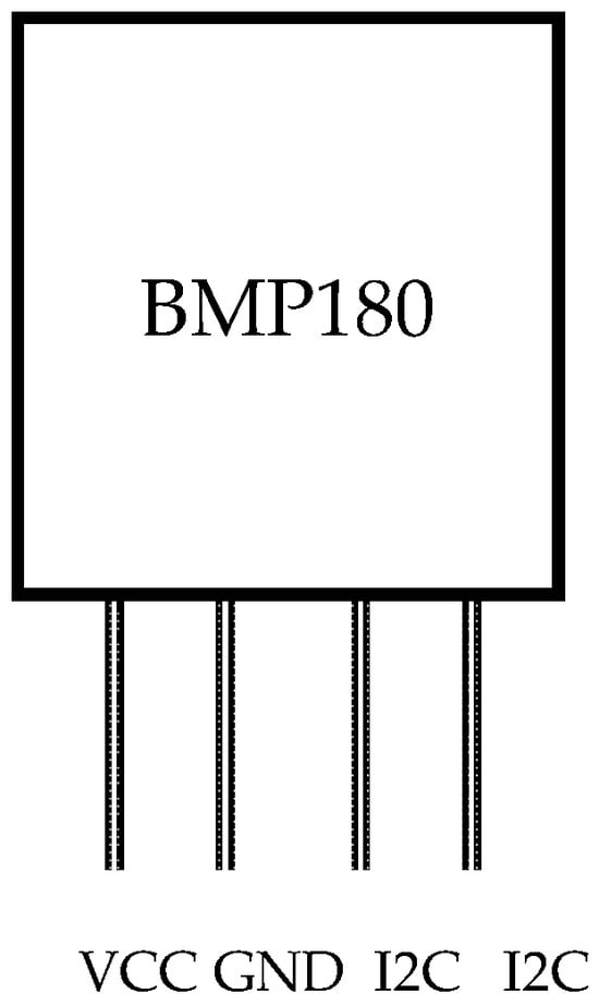
Figure 3.
A schematic of the BMP180 sensor.
The main technical characteristics of the BMP180 sensor are shown in Table 4.
Table 4.
Technical characteristics of the BMP180 sensor.
2.3. The MQ7 Sensor
The MQ7 sensor measures the concentration of CO [20]. Its operation is based on a variable resistor whose material reacts with the atmospheric CO resulting in the change in its resistance. The typical CO concentration range is from 20 to 2000 ppm. The sensor includes six pins, of which four are used for signal reception and two for power supply (a voltage of 5 V).
2.4. The Arduino Uno Module
The Arduino Uno (R3) module (Figure 4 [21] and Table 5 [2]) has 14 digital input/output pins (numbered 0,…, 13) and six analog input pins (named A0,…, A5). Six of the fourteen digital ports, that is 3, 5, 6, 9, 10, and 11, are also pulse-width-modulation (PWM) ports, which means that they can also simulate analog outputs. The side with the analog pins also includes the pins for the module’s power supply. Each digital input/output involves digital signals of 0 or 5 V while the analog signals have values between 0 and 5 V. The activation of the Arduino Uno functions is achieved through the “Integrated Development Environment” (IDE), available at [22], which is compatible with all the existing variants of Arduino boards and can run on Windows, Linux and MacOS. Programming of the module is made by means of the “Wiring” language which is a variation in C++.
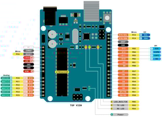
Figure 4.
The Arduino Uno module (top view) [21].
Table 5.
Technical characteristics of Arduino-Uno [2].
The Arduino-Uno board is programmed by following the procedure shown in Figure 5. First, the developer downloads IDE to a computer which is then connected to the Arduino board through a USB port. Then, the developer writes the Arduino code (by using a simplified version of C++) on the IDE right on the computer system. An IDE start-up screen typically includes a menu line (with buttons such as “File”, “Edit”, etc.), a toolbar (with buttons such a “Verify”, “Upload”, “New”, “Open”, “Save”, etc.), a text editor (where the code can be written), a message area (for providing feedback including error messages) and a status bar (with info such as the board type, the USB port though which the computer is interconnected to the board, etc.). Once written, the code is uploaded to the microcontroller that executes the code (after compiling it by means of the so-called “avr-g++” compiler). Finally, the microcontroller interacts with the inputs and outputs from the system’s sensors [2].
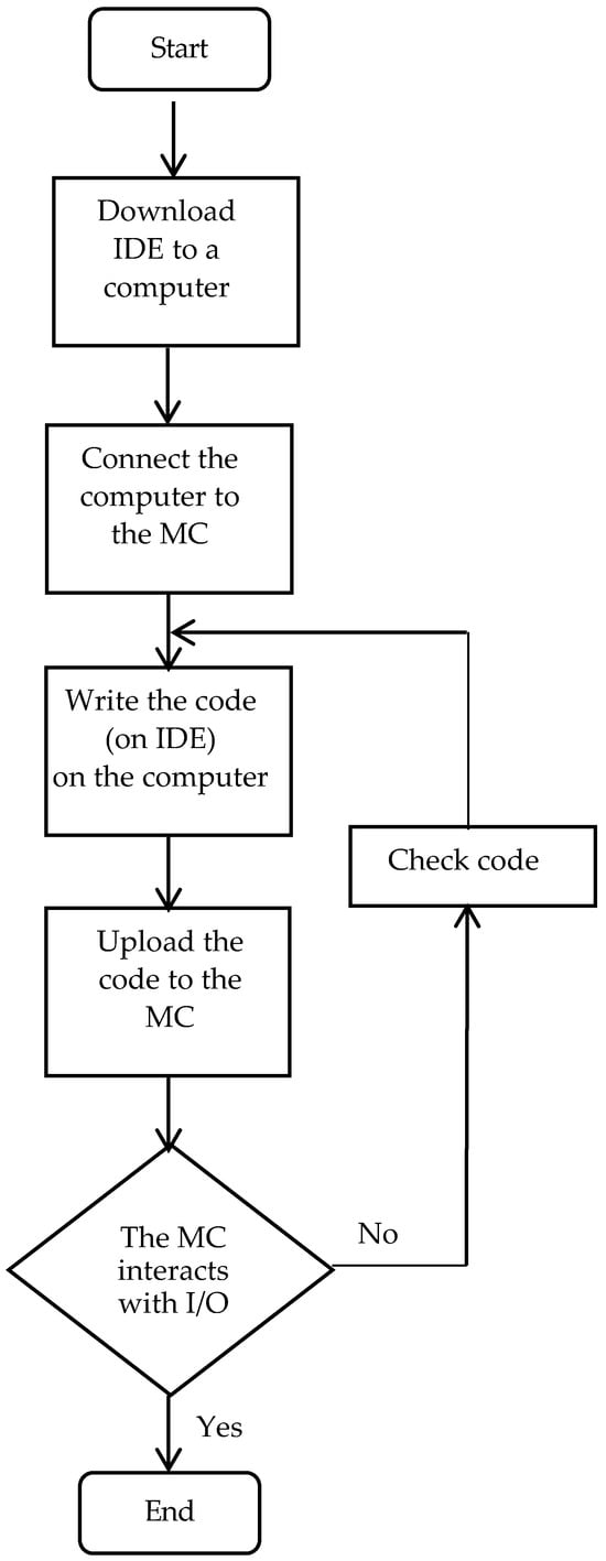
Figure 5.
The basic steps of Arduino programming.
2.5. The GSM SIM900 Module
The GSM SIM900 module [23] enables easy connection to mobile telephony network, by simply using a SIM card. The main chip of the module is SIM900 which is a low-cost GSM/GPRS modem. SIM900 supports AT commands by a serial UART. Through those commands the module makes it possible to make phone calls, send and receive text messages (SMSs), and connect to the Internet thus enabling access to the IoT.
The main technical characteristics of the GSM SIM900 module are shown in Table 6.
Table 6.
Technical characteristics of the GSM SIM900 module.
Connection of the GSM SIM900 module to the Arduino Uno module is achieved by inserting a SIM card in the respective socket while the powering-up of the GSM SIM900 is performed either from the Arduino-Uno or from an external source.
2.6. The Buzzer
The buzzer contains a piezoelectric element that can produce a sound signal of a specific frequency. Regarding the described system, the buzzer is activated when the temperature exceeds 35 °C.
2.7. ThingSpeak
ThingSpeak is an open-source IoT application and application programming interface (API) for storing and retrieving data from devices using the HTTP protocol over the Internet or over a local network [24]. Among others, ThingSpeak enables the creation of sensor logging applications and location tracking applications with status updates and it also has a built-in support of MathWorks’s MATLAB software that allows users to analyze and visualize uploaded data using MATLAB.
Merits of ThingSpeak include easy configuration of devices for sending data by means of popular IoT protocols, real-time visualization of data entered by the system’s sensors, aggregated data on demand from third-party sources, automatic data movement and communication using third-party services such as X (former Twitter), and the use of MATLAB for data analysis and visualization.
3. The System’s Operation
A conceptual and a block diagram of the proposed weather monitoring system is illustrated in Figure 6. A photo of the actual system is shown in Figure 7.
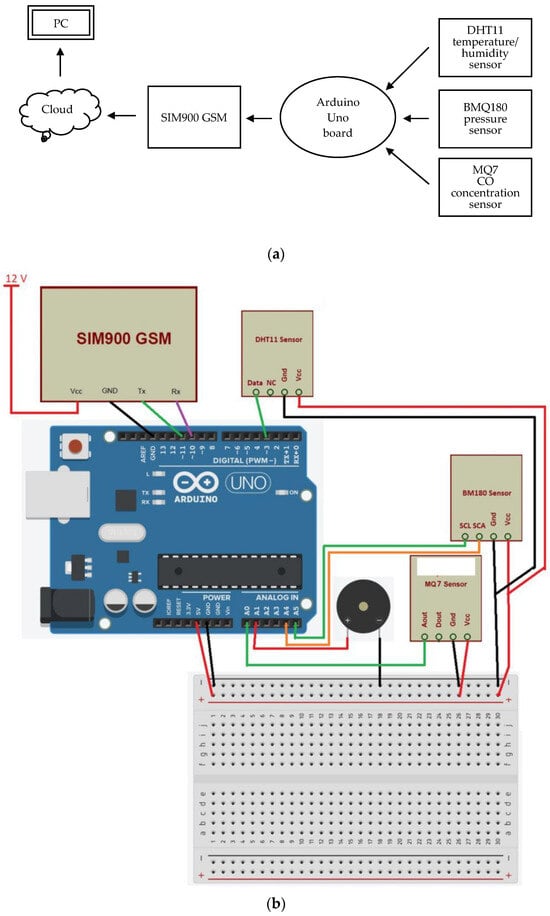
Figure 6.
(a) A conceptual diagram and (b) a block diagram of the weather monitoring system.
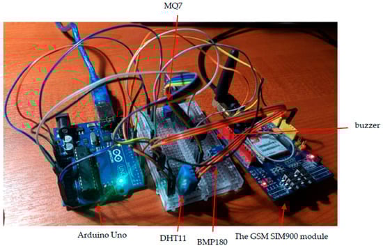
Figure 7.
The weather monitoring system (photo).
The Arduino Uno board gathers the data collected by the sensors and, by means of the GSM SIM900 module, it transmits the data to the Cloud. It achieves that by means of ThingSpeak, which, among others, enables saving and recovering of the sensing and monitoring data. Due to the use of the mobile telephony network (instead of wireless technologies such as Zigbee and Bluetooth), the proposed system has an enhanced availability and portability and is easy to use. Weather data are received by a computer; however, they can also be received on a mobile phone by employing the phone’s browser and connecting to ThingSpeak.
Figure 8 depicts a flowchart of the system’s operation. After the setting-up and initialization phase, the setup function signals the start of the system’s operation which continues through the repeated execution of the loop function, resulting in data being uploaded to ThingSpeak.
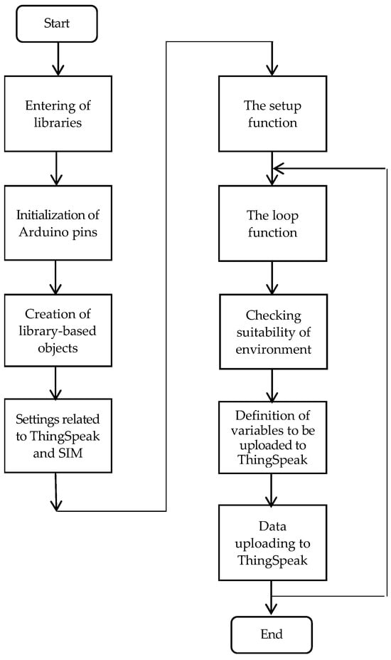
Figure 8.
Flowchart of the system’s operation.
The proposed system was tested by implementing real-time measurements regarding relative humidity, temperature, sensible temperature, atmospheric pressure and CO concentration. In Figure 9, a typical screenshot is shown with consecutive measurements regarding the above parameters. At the same time, the relative humidity and temperature measurements were graphically recorded with respect to time, as shown in Figure 10.
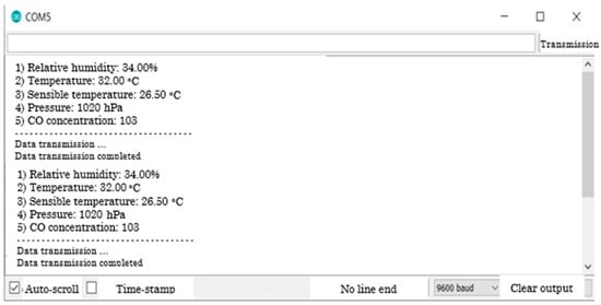
Figure 9.
A screenshot with consecutive real-time measurements (readings have been translated to English). RH = 34%, T = 32 °C, sensible temperature = 26.5 °C, pressure = 1020 hPa, CO concentration = 103 ppb (parts per billion).
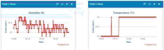
Figure 10.
Graphs of relative humidity and temperature measurements with respect to time.
To validate measurements, the results were compared with those of conventional temperature, relative humidity, and pressure measuring devices. In all cases, the difference between the respective measurements was within 5%, which is compatible with the DHT11 and BMP180 sensors’ accuracy.
4. Discussion
The cost of the described system is analyzed in Table 7. The overall cost is estimated at about EUR 98, which makes the system a flexible, low-cost solution for real-time, remote monitoring of essential environmental parameters in spaces such as farms, warehouses, rooms, etc. The monthly cost of using the GSM (e.g., through a 1 GB data package) is about EUR 5. Apart from [10], there is no cost-related info mentioned in the literature; however, given that most of those systems are also based on the Arduino-Uno board together with the fact that the cost of the rest of the hardware components is only between EUR 1 and 6, it can be concluded that the cost of the described system should be at least comparable with that of the systems presented in the literature. On the other hand, the cost of a commercial weather monitoring system with a reasonable accuracy and durability is estimated to about EUR 180–360 (excluding the transmission module).
Table 7.
Cost of the weather monitoring system.
The system’s power consumption is estimated to about 1–2 W, mainly due to the use of the GSM module. Since powering the system by a conventional 9 V battery could only last for about 5–10 min, the use of a solar panel could be an option in cases where powering though the grid is not possible.
The prototype described in this paper can be considered to have a technology readiness level (TRL) equal to 5, which corresponds to the components and/or breadboard validation in relevant environment [25].
Possible improvements that could be applied to the described system include the following:
- A smartphone application that would enable data supervision. This can be achieved by properly programming the Arduino for the GSM module to transmit an SMS, e.g., every 30 min.
- Incorporation of additional sensors, for, e.g., luminosity, wind speed/direction, soil moisture, etc.
- Use of higher-performance (e.g., industrial) sensors.
- Addition of an LCD for displaying sensors’ data.
- Addition of a camera for receiving live images.
It is estimated that the above improvements would increase the cost of the system by about EUR 200 (which still makes it a viable solution given that a commercial system should at least cost EUR 180–360 excluding the transmission module).
The system could also anticipate more alarms (e.g., when the relative humidity exceeds some value) and/or be upgraded in order to interoperate with equipment such as air-conditioners and/or dehumidifiers that could be automatically activated in order to regulate environmental conditions in closed spaces such as rooms and warehouses. Depending on the particular application, the potential user might also choose either not to measure the CO concentration (and remove the MQ7 sensor) or measure it by means of a higher performance sensor or even extend the system’s use to the sensing of more dangerous gases such as carbon-dioxide (CO2) and methane (CH4). All in all, and owing to its modularity and scalability, the system can be customized to meet the needs of the particular application for which it is intended.
Further future improvements could include:
- The use of a printed-circuit board (PCB) instead of a breadboard.
- The development of the system by using integrated sensors and system-on-chip technology.
- Powering of the system by means of rechargeable batteries or solar panels.
- An enhanced set of experimental results that would be thoroughly tested through a relevant statistical analysis. This could also help in upgrading the TRL of the system (e.g., to 6).
Apart from the technical aspect, Arduino-based projects, like the one described in this article, can also serve as didactical tools due to the fact that such projects usually require the combination of different knowledge subjects while involving cooperative and inquiry-based learning in accordance with the STEM principles. This is particularly important for students who would like be employed as teachers in technology-oriented schools after their graduation. In this context, the development of the described weather station can be considered as a rich activity that comprises all three types of knowledge (content, pedagogical, and technological) of the TPACK framework [26] and all six levels (remember, understand, apply, analyze, evaluate, create) of Bloom’s taxonomy [27].
5. Conclusions
A weather monitoring system capable of measuring temperature, relative humidity, atmospheric pressure and CO concentration was described. The system uses low-cost, widely available sensors connected to an Arduino-Uno module, and transmits the collected data to the Cloud by means of GSM SIM900 module. The main novelty of the proposed system is the combined use of the GSM network (with the aim to employ its wide coverage) the Cloud and the IoT. The system has the merits of easy development, low cost (less than EUR 100), and low power consumption, combined with enhanced availability and portability due to the use of the mobile telephony network. The system is modular and scalable and can be customized according to the needs of the particular application for which it is intended since sensors can be added or removed at will.
The proposed system was tested by implementing a set of measurements (regarding temperature, relative humidity, sensible temperature, atmospheric pressure, and CO concentration) and comparing them with those of conventional temperature-, relative-humidity-, and pressure-measuring devices. In all cases, the difference was lower that 5%, compatible with the DHT11 and BMP180 sensors’ accuracy.
Possible improvements in the described systems could be the incorporation of additional and/or higher-performance sensors, the addition of an LCD and/or a camera, the employment of a PCB (instead of a breadboard), the use of integrated sensors and system-on-chip technology, powering the system by means of rechargeable batteries or solar panels, and the gathering and statistical analysis of an enhanced set of experimental results.
Finally, apart from the technical aspect, projects such as the one described in this article can also cover didactical objectives in engineering education.
Author Contributions
Investigation, I.M., P.M. and P.T.; software, I.M., P.M. and P.T.; data curation, I.M.; writing—original draft preparation, G.P., A.P. and L.D.; writing—review and editing, I.M., G.P., A.P. and L.D.; supervision, G.P.; project administration, G.P. All authors have read and agreed to the published version of the manuscript.
Funding
This research received no external funding.
Data Availability Statement
The original contributions presented in this study are included in the article. Further inquiries can be directed to the corresponding author.
Conflicts of Interest
The authors declare no conflicts of interest.
References
- Louis, L. Working principle of Arduino and using IT as a tool for study and research. Int. J. Control Autom. Commun. Syst. 2016, 1, 21–29. [Google Scholar] [CrossRef]
- Kondaveti, H.K.; Kumaravelu, N.K.; Vanambathina, S.D.; Mathe, S.E.; Vappani, S. A systematic literature review on prototyping with Arduino. Comput. Sci. Rev. 2021, 40, 2–28. [Google Scholar] [CrossRef]
- Mircea, P.; Catalin, I. Embedded Weather station with remote wireless control. In Proceedings of the 19th Telecommunications Forum (TELFOR), Belgrade, Serbia, 22–24 November 2011. [Google Scholar]
- Hosamani, R.; Sujathakumari, B.A. Wireless Weather Data Logger Using SD Card with ARM Controller; Visvesvaraya Technological University Belgaum: Karnataka, India, 2010. [Google Scholar]
- Ferdoush, S.; Li, X. Wireless Sensor Network System Design using Raspberry Pi and Arduino for Environmental Monitoring Applications. Procedia Comput. Sci. 2014, 34, 103–110. [Google Scholar] [CrossRef]
- Sabharwal, N.; Kumar, R.; Thakur, A.; Sharma, J. A low-cost Zigbee based automatic wireless weather station with GUI and web hosting facility. Int. J. Electr. Electron. Eng. 2014, 1, 258–263. [Google Scholar]
- Krishnamurthi, K.; Thapa, S.; Kothari, L.; Prakash, A. Arduino based weather monitoring system. Int. J. Eng. Res. Gen. Sci. 2015, 3, 452–458. [Google Scholar]
- Chawla, A.; Bangera, T.; Kolwalkar, C.; Bhat, M. Bluetooth-based weather station. Int. J. Eng. Trends Technol. 2015, 2, 98–101. [Google Scholar] [CrossRef]
- Saefullah, A.; Sunarya, A.; Fakhrizal, D. Prototype Weather Station Berbasis Arduino Yun. Creat. Commun. Innov. Technol. J. 2015, 8, 57–65. [Google Scholar] [CrossRef]
- Mesas-Carrascosa, F.J.; Verdu Santano, D.; Merono, J.E.; Sanchez de la Orden, M.; Garcıa-Ferrer, A. Open source hardware to monitor environmental parameters in precision agriculture. Biosyst. Eng. 2015, 137, 73–83. [Google Scholar] [CrossRef]
- Saini, H.; Thakur, A.; Ahuja, S.; Sabharwal, N.; Kumar, N. Arduino based automatic wireless weather station with remote graphical applications and alerts. In Proceedings of the 3rd International Conference on Signal Processing and Integrated Networks (SPIN), Noida, India, 11–12 February 2016. [Google Scholar]
- Rao, B.S.; Rao, K.S.; Ome, N. Internet of Things (IoT) based weather monitoring system. Int. J. Adv. Res. Comput. Commun. Eng. 2016, 5, 312–319. [Google Scholar]
- Mahmood, S.N.; Hasan, F.F. Design of weather monitoring system using Arduino-based database implementation. J. Multidiscip. Eng. Sci. Technol. 2017, 4, 7109–7117. [Google Scholar]
- Girija, C.; Shires, A.G.; Harsalatha, H.; Pushpalatha, H.P. Internet of Things (IoT) based weather monitoring system. Int. J. Eng. Res. Technol. 2018, 6, 1–4. [Google Scholar]
- Sidqi, R.; Rynaldo, B.R.; Suroso, S.H.; Firmansyah, R. Arduino based weather monitoring telemetry system using NRF24L01+. IOP Conf. Ser. Mater. Sci. Eng. 2018, 336, 012024. [Google Scholar] [CrossRef]
- Holovatyy, A. Development of IOT weather monitoring system based on Arduino and ESP8266 Wi-Fi Module. IOP Conf. Ser. Mater. Sci. Eng. 2021, 1, 012014. [Google Scholar] [CrossRef]
- Liyakat, K.S.S.; Liyakat, K.K.S. Arduino based weather monitoring system. J. Health Syst. Res. 2023, 8, 24–29. [Google Scholar]
- Mouser Electronics, Munich, Germany. DHT11 Humidity & Temperature Sensor. Available online: https://www.mouser.com/datasheet/2/758/DHT11-Technical-Data-Sheet-Translated-Version-1143054.pdf?srsltid=AfmBOoqBzEvf7Kjxa6huTH5bRzOyYxn6rCvpGPspNJnf-PtrZhrwZpmG (accessed on 17 December 2024).
- Bosch GmbH. BMP180 Digital Pressure Sensor. BMP180 Datasheet (2/29 Pages) BOSCH|Digital Pressure Sensor. Available online: https://www.alldatasheet.com/html-pdf/1132068/BOSCH/BMP180/353/2/BMP180.html (accessed on 17 December 2024).
- Hanwei Electronics Co. Ltd., Zhengzhou, China. MQ-7. Available online: http://www.hwsensor.com (accessed on 17 December 2024).
- UNO R3. Arduino UNO Rev3 with Long Pins|Arduino Documentation. Available online: https://docs.arduino.cc/retired/boards/arduino-uno-rev3-with-long-pins/ (accessed on 17 December 2024).
- Arduino IDE 2.3.4. Available online: www.arduino.cc/en/software (accessed on 17 December 2024).
- Grobotronics, Athens, Greece. GSM SIM900. GSM/GPRS Shield for Arduino SIM900. Available online: https://grobotronics.com/gsm-gprs-shield-for-arduino-sim900.html?srsltid=AfmBOor6xLlkolNLYSfNa9j8UEDzgDh8pVctlNtQ_SoZZQ_g73-TTxzt (accessed on 17 December 2024).
- Learn More About Thingspeak. Available online: https://thingspeak.com/pages/learn_more (accessed on 17 December 2024).
- Heder, M. From NASA to EU: The evolution of the TRL scale in Public Sector Innovation. Innov. J. 2017, 22, 3. [Google Scholar]
- Mishra, P.; Kohler, M.J. Technological pedagogical content knowledge: A framework for integrating technology in teacher knowledge. Teach. Coll. Rec. 2006, 108, 1017–1054. [Google Scholar] [CrossRef]
- Armstrong, P. Bloom’s taxonomy. Vanterbilt University Center for Teaching. Available online: https://cft.vanderbilt.edu/guides-sub-pages/blooms-taxonomy (accessed on 12 September 2023).
Disclaimer/Publisher’s Note: The statements, opinions and data contained in all publications are solely those of the individual author(s) and contributor(s) and not of MDPI and/or the editor(s). MDPI and/or the editor(s) disclaim responsibility for any injury to people or property resulting from any ideas, methods, instructions or products referred to in the content. |
© 2025 by the authors. Licensee MDPI, Basel, Switzerland. This article is an open access article distributed under the terms and conditions of the Creative Commons Attribution (CC BY) license (https://creativecommons.org/licenses/by/4.0/).