Article

Research on Path Planning for Mobile Charging Robots Based on Improved A* and DWA Algorithms

School of Mechanical Engineering, Jiangsu Ocean University, Lianyungang 222005, China
*
Author to whom correspondence should be addressed.
Electronics 2025, 14(12), 2318; https://doi.org/10.3390/electronics14122318
Submission received: 25 April 2025 / Revised: 3 June 2025 / Accepted: 4 June 2025 / Published: 6 June 2025

Abstract

Driven by rapid growth in the new-energy vehicle (NEV) market and advances in automation, mobile charging robots are increasingly deployed in parking facilities. In complex environments featuring both static and dynamic obstacles, conventional trajectory plans often exhibit insufficient safety margins and poor smoothness. This paper proposes a hybrid path-planning strategy that combines an improved A* algorithm with an enhanced dynamic window approach (DWA). The enhanced A* algorithm incorporates obstacle influence factors and adaptive weighting during global search, enabling proactive avoidance of obstacle-dense regions and employing segmented Bezier curves for path smoothing. In local planning, the modified DWA integrates a global guidance term and distance-dependent heading weights to mitigate issues of local minima and target loss. Simulation results indicate that the proposed method substantially improves path safety, continuity, and adaptability to complex scenarios while maintaining computational efficiency. Specifically, under high-obstacle-density conditions (e.g., a 20 × 20 grid map), the collision rate is reduced by 66.7% compared to the standard A* algorithm (from 30% to 10%), and the minimum safety distance increases to 0.5 m. Current validation is conducted in simulations; future work will involve real-robot experiments to evaluate real-time performance and robustness in practical environments.

1. Introduction

In recent years, with the rapid development of the new-energy vehicle industry, the traditional charging mode of “drivers seeking charging piles” has gradually been replaced by the new concept of “charging piles seeking drivers”. The congestion and space limitations of fixed charging stations increasingly fail to meet the growing demand for efficient charging, driving the evolution of charging methods toward more flexible and distributed solutions. To address the technical requirements for flexible power supply to multiple devices, Reference [1] proposes an inductive power transfer (IPT) system with dual transmitters for IoT scenarios, which can simultaneously provide stable and efficient wireless charging for multiple autonomous catering vehicles in limited spaces. Its diverted magnetic field and multi-receiver coupling design offer an engineering approach for flexible power supply systems. This distributed power architecture reflects the gradual shift of charging systems from static charging piles to mobile and modular configurations. Against this backdrop, mobile charging robots [2] have emerged, providing capabilities such as on-demand mobility, localized power supply, and multi-robot scheduling, effectively alleviating the deployment adaptability limitations of traditional charging stations. A mobile charging robot is shown in Figure 1. Additionally, in closed and complex environments such as parking lots, dense obstacles and intertwined traffic flows pose significant challenges to the path planning of charging robots. To ensure charging efficiency while achieving smooth obstacle avoidance and precise navigation in narrow spaces [3], research on path planning for mobile charging robots has important theoretical and practical significance.
Path planning can be categorized into global and local path planning algorithms based on the static and dynamic information of the map. Common global path planning algorithms include Dijkstra’s algorithm, Best-First Search (BFS), and Rapidly-exploring Random Trees (RRT), each with unique characteristics but certain limitations. Dijkstra’s algorithm can find globally optimal paths in non-negatively weighted graphs, but it has high computational complexity, slow expansion speed, and is unsuitable for large-scale scenarios [4]; the BFS algorithm is applicable to discrete grid environments, capable of traversing all possible paths and guaranteeing a solution, but it exhibits low search efficiency and consumes excessive computational resources in high-dimensional spaces [5]; the RRT algorithm constructs feasible paths quickly through random sampling, which is suitable for complex continuous spaces and high-dimensional environments. However, the generated paths are usually discrete and require subsequent optimization to meet the robot’s kinematic constraints [6]. In contrast to other algorithms, the A* algorithm utilizes heuristic search to minimize invalid node expansion, enhance computational efficiency, and reduce computational costs while guaranteeing optimality. Thus, it has been widely adopted in pathfinding research. To address the issues of excessive node traversal and large turning angles—both of which increase obstacle collision risks—Junfeng Bai et al. [7] replaced the original four-neighborhood search with an eight-neighborhood search during pathfinding. Meanwhile, Erke et al. [8] effectively addressed excessive turning and collision risks near obstacles by introducing an evaluation criterion parameter into the cost function. Qianzhan Qi et al. [9] proposed a heuristic function fusing Euclidean and Manhattan distances, using adaptive weight factors to significantly enhance search efficiency. However, their method lacked explicit obstacle avoidance mechanisms, leaving the algorithm vulnerable to collisions in cluttered environments. In addition, Lisang Liu et al. [10] optimized the storage structures of the open and closed lists by integrating an obstacle function, thereby improving search efficiency. Zhongyu Wang et al. [11] proposed a static weight allocation strategy for the evaluation function to address obstacle avoidance challenges, reducing redundant nodes and inflection points in path generation. Xiaohui Li et al. [12] improved obstacle avoidance efficiency by using an array to store node information and combining A*’s heuristic search with a path repair strategy, but their approach had limited applicability and failed to account for dynamic obstacles. Further, Fenglian Qi et al. [13] enhanced algorithm efficiency and solved obstacle collision issues by introducing heuristic function weight coefficients and obstacle safety distances. Jia et al. [14] proposed a multi-objective optimization function based on quintic Bezier curves, fusing curvature smoothness and path length with dynamic obstacle constraints to ensure both obstacle avoidance and path smoothness. Liu et al. [15] introduced a hybrid heuristic function and adaptive global path yaw angle to improve path smoothness by reducing search nodes, though the algorithm’s complexity limited its applicability in highly dynamic environments.
The accuracy and real-time performance of dynamic obstacle avoidance are crucial factors affecting robotic operations. Local path planning for this task relies on algorithms that balance responsiveness and safety, primarily including fuzzy control, the artificial potential field method (APF), neural networks, and the dynamic window approach (DWA) [16]. Hongbin Wang et al. [17] enhanced APF flexibility by integrating velocity-dependent factors into gravitational and repulsive potential fields, introducing virtual subgoals and adaptive step sizes to improve robot adaptability in dynamic environments. Recognizing that single-method optimizations have limited scope, researchers have increasingly adopted hybrid approaches. Liu et al. [18] formulated multi-objective optimization problems incorporating trajectory time, energy consumption, and smoothness, leveraging evolutionary algorithms to find optimal trade-offs. The dynamic window approach (DWA) stands out for its real-time obstacle avoidance accuracy, motion feasibility, and trajectory continuity, making it a popular research target. Huayang Jiang et al. [19] optimized its evaluation function through normalization, enhancing the algorithm’s ability to balance speed, safety, and target convergence for mobile charging robots in complex environments. Lin et al. [20] designed a dual-input dual-output fuzzy controller integrated with collision risk indices (based on relative velocity and distance) and fuzzy rules, enabling robots to dynamically adjust direction and avoid moving obstacles by leveraging environmental feedback.
Hybrid planning strategies combining global and local algorithms have emerged as a leading solution through which to overcome the limitations of single-layer planners, particularly in balancing long-range path optimality with real-time obstacle avoidance in dynamic, complex environments. For mobile robots, Hongxia Yang et al. [21] proposed a novel hybrid approach fusing an improved A* algorithm with an enhanced dynamic window approach (DWA), aiming to strengthen path safety and obstacle avoidance capabilities. The improved A* algorithm enhances search efficiency through a refined heuristic function, while a path-smoothing mechanism eliminates abrupt turns, significantly improving the feasibility of global trajectories. Concurrently, the enhanced DWA integrates a path deviation penalty term and dynamic obstacle risk assessment, enabling the robot to respond swiftly and safely in cluttered, dynamic scenarios. In marine applications, similar hybrid frameworks have been adapted for unmanned surface vehicles (USVs). Yuchao Wang et al. [22] developed a planner combining an improved Artificial Potential Field–Rapidly-exploring Random Tree (APF-RRT) algorithm with DWA to address kinematic constraints and maritime collision regulations (COLREGS). By introducing a direction-guided dynamic potential field into the RRT framework, this method enhances path continuity and avoids local minima, while embedding COLREGS-based constraints into the DWA cost function ensures compliant and effective local obstacle avoidance. These hybrid approaches demonstrate notable improvements in global path quality, obstacle avoidance robustness, and safety margins, providing practical navigation solutions for both terrestrial and maritime autonomous systems.
In summary, the mobile charging robot path planning algorithm must not only construct optimal paths in static environments but must also enable real-time adaptability to dynamic obstacles, ensuring safe and smooth robot movement. To address these challenges, this paper proposes a hybrid path planning method for mobile charging robots, integrating an improved A* algorithm and an enhanced dynamic window approach (DWA). The specific contributions are as follows:
  • Aiming at the traditional A* algorithm’s insufficient obstacle avoidance in evaluation functions, this study introduces an obstacle influence factor and employs dynamic weight coefficients to balance global search optimality and local obstacle avoidance. This approach effectively reduces path deviation caused by obstacles, improving both the efficiency and safety of path planning in cluttered environments.
  • To solve the problem of non-smooth motion due to excessive turning points in A*-generated paths, segmented Bezier curve optimization is applied to eliminate sharp angles and trajectory discontinuities. This method significantly enhances path smoothness, ensuring better compliance with the robot’s kinematic constraints and reducing motion instability in narrow spaces.
  • Addressing the common issues of target loss and local minima in the standard DWA, this paper integrates a global guidance term and distance-dependent heading weights into the local evaluation function. These modifications enable the robot to maintain steady progress toward the target while dynamically avoiding moving obstacles, fundamentally improving the directivity and real-time adaptability of path planning in complex scenarios.

2. A* Algorithm Optimization

2.1. Traditional A* Algorithm

The A* algorithm, a graph-based global path planning method, is widely applied in robot navigation, game development, and other graph search domains. It determines the optimal path from a start node to a goal node by integrating two key components in its evaluation function: the actual cost from the start to the current node and a heuristic estimate of the remaining cost to the goal. The core evaluation function of A* is defined as
F n = G n + H n
where F ( n ) represents the evaluation function of the planning path, G ( n ) represents the actual cost from the starting point ( x s , y s ) to the current point ( x , y ) , and H ( n ) represents the estimated cost from the current point ( x , y ) to the target point ( x g , y g ) . In this paper, Manhattan distance is chosen as the calculation method of the heuristic function. The calculation method is as follows:
H n = x 1 x 2 + y 1 y 2
Using Manhattan distance can not only better reflect the directional restriction of robot driving but can also improve the efficiency of path planning.

2.2. A* Algorithm Heuristic Function Optimization

The main problems of traditional A* algorithms are that over-reliance on G ( n ) leads to over-scaling, and over-reliance on H ( n ) misses the optimal path. Heuristic function design is crucial to the optimality and efficiency of the algorithm. A proper heuristic function can reduce the search space and speed up the computation, while an inappropriate heuristic function may reduce efficiency or fail to guarantee the optimal solution.
In order to optimize the performance of the A* algorithm, this paper introduces the obstacle influence degree O b ( n ) , which is used to reflect the influence of obstacles near the current node on the path planning, on the basis of the traditional evaluation function:
O b n = i = 1 M 1 1 + d i s t n , O i
In this equation, M denotes the total number of obstacles in the environment, O i = ( x i , y i ) represents the spatial coordinate of the i obstacle, and d i s t ( n , O i ) = ( x n x i ) 2 + ( y n y i ) 2 calculates the Euclidean distance between node n and obstacle O i . Through the obstacle influence factor defined in Equation (3), the obstacle impact intensity decreases gradually with increasing distance, meaning the closer a node is to an obstacle, the more significant the influence it experiences. This mechanism helps to guide the mobile charging robot to avoid obstacle-dense areas and reduces collision risks during path planning. Additionally, to enhance the efficiency and quality of the A* algorithm’s path planning, adaptive weight coefficients ω 1 and ω 2 are employed to dynamically balance the relationship between various parameters of the evaluation function. The new evaluation function is as follows:
F n = G n + ω 1 H n + ω 2 O b n
In this formula,
ω 1 ( E , P ) = ω b a s e 1 + Δ ω s ( E , P ) ω 2 ( E , P ) = ω b a s e 2 Δ ω s ( E , P )
s ( E , P ) = e ( E 2 ) 1 1 + P
E = N o b s π r 2
P = 1 ( x g x ) 2 + ( y g y ) 2 ( x g x s ) 2 + ( y g x s ) 2
where ω b a s e 1 and ω b a s e 2 are both set to 1 (as the initial weights); the moderator function s ( E , P ) is composed of the environmental complexity function E and the path search progress function P , and Δ ω (set to 0.2) denotes the moderating magnitude of the moderator function on ω 1 and ω 2 .
Specifically, the coupling function s ( E , P ) plays a critical role in dynamically adjusting the weights in response to changing environments. By simultaneously accounting for the environmental complexity E (i.e., obstacle density per unit area) and the search progress P (i.e., the ratio of current remaining distance to the initial distance), it enables the dynamic interplay between heuristic weight ω 1 and obstacle avoidance weight ω 2 , which are under mutual restriction, thus establishing a complementary equilibrium. Firstly, when the environmental complexity E increases (indicating a rise in obstacle density), the value of s ( E , P ) rapidly decreases. This decrease causes ω 2 to increase accordingly, thereby prioritizing local avoidance capabilities in densely obstructed regions; simultaneously, ω 1 is purposefully reduced to prevent the heuristic term from dominating and becoming trapped in a local suboptimal solution. Conversely, as the robot approaches the goal and the remaining path distance P decreases, s ( E , P ) likewise diminishes. Under these conditions, ω 1 is swiftly elevated to accelerate global convergence toward the goal, while ω 2 is concurrently decreased to minimize unnecessary detours around sparse obstacles, thus shortening the overall path length. To prevent excessive oscillations, upper and lower bounds are imposed on ω 1 and ω 2 . Furthermore, the exponential decay in E guarantees rapid responsiveness when obstacle density spikes, and the reciprocal decay in P secures steadily strengthened heuristic guidance as the remaining distance shrinks. Hence, the proposed formulation inherently balances local safety with global efficiency, directly supporting the objectives of real-time adaptability and robust path planning performance.
For the purpose of verifying the validity as well as the feasibility of the dynamic weight coefficients, a 20 × 20 grid map is used for testing, alongside the evaluation function from the literature [8], the evaluation function of the traditional algorithm, and the improved evaluation function, which are for simulation. The simulation results are shown in Figure 2.
Figure 2 and Table 1 reveal that the algorithm in the literature [8] has the smallest number of searched nodes, yet its search time is the longest. Moreover, neither the inflection point nor the path length is optimal. Additionally, the planned paths collide with obstacles, similar to traditional algorithms, which is highly unfavorable for the motion planning of mobile charging robots in real-world scenarios. In terms of the number of searched nodes, the improved algorithm’s evaluation function is inferior to that of the algorithm in the literature [8]. However, compared with the traditional algorithm, both the search time and the number of searched nodes of the algorithm in this paper are improved. Furthermore, the path planned by the improved algorithm exhibits no collision phenomenon, which is highly beneficial to the security of mobile charging robot planning. The improved evaluation function can effectively balance search efficiency and path quality, thereby verifying the feasibility and effectiveness of the improved evaluation function.
Table 1 and Figure 2 present a performance comparison of three algorithms. The reference algorithm from [8], despite examining the fewest search nodes (72), incurs the longest search time (0.033 s), and neither its path length (27.38 m) nor its minimum safety distance (MSD = 0 m) is satisfactory; more critically, its collision rate (CR)—which reflects the incidence of collisions during path generation—reaches 37.5%, with the planned path exhibiting severe collisions with obstacles (Figure 2a), such that its safety performance is wholly inadequate for practical deployment. By contrast, the conventional algorithm achieves a shorter search time (0.018 s) but explores a larger number of nodes (126). Although its path length (25.97 m) and MSD (0 m) remain unchanged compared to the reference algorithm, it nonetheless suffers a 30% CR—indicating that nearly one-third of generated paths collide with obstacles—and demonstrates evident path–obstacle conflicts (Figure 2b), indicating substantial safety risks. In stark contrast, the improved algorithm delivers a qualitative breakthrough in core safety metrics; its CR is reduced to 10%, and its MSD is increased to 0.5 m, so that the planned path (Figure 2c) remains entirely collision-free. Consequently, its safety performance is enhanced threefold relative to the conventional algorithm and nearly fourfold relative to the reference algorithm. Notably, the MSD directly correlates with CR; an MSD of 0 gives no buffer against obstacles, resulting in high collision likelihood (CR > 30%), whereas an MSD of 0.5 m provides a robust clearance margin that translates into a substantial CR reduction. The improved evaluation function thus effectively balances search efficiency, path quality, and a non-zero MSD, thereby verifying its feasibility and effectiveness.

2.3. Bezier Curve Smoothing Path

The Bezier curve is widely used for path smoothing. It can generate a smooth path through several control points. The Bezier curve is a set P = { P 0 , P 1 , , P n } consisting of n + 1 control points. The Bezier curve of order n is expressed as follows:
B t = i = 0 n C n i 1 t n i t i P , t [ 0 , 1 ]
The evaluation function with dynamic weights enhances the path search process and elevates the adaptability of path planning. Nevertheless, as the search process is still impacted by the discretization of the grid map, the generated paths frequently possess numerous inflection points. This gives rise to frequent sharp turns or even transient halts of the mobile charging robot during its travel. Hence, to further enhance the practicality and continuity of the paths, dynamic-order Bezier curves proposed in this study are utilized to fit the paths, improving their smoothness and enabling the robot to comply with kinematic constraints. Therefore, the optimization is conducted considering both path segmentation and curvature constraints, and the specific process is as follows.
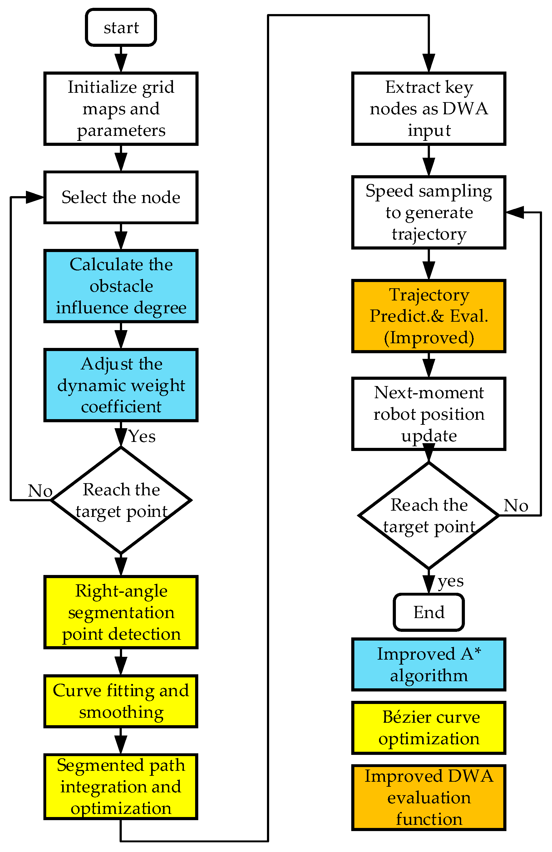
  • Detect right angle points and split the path iteratively over the neighboring nodes m , m + 1 , m + 2 in the path; calculate the angle at the node m + 1 . If this angle is close to 90° (The error is ±5°), the node m + 1 is labeled as a right-angle point, and this is used as the dividing point to split the path into sub-segments. Each sub-segment contains several consecutive nodes until the next right-angle point or the end of the path. If the angle of a node m + 1 does not meet the conditions of a right angle, then continue to check the next node until the end of the path.
  • For each sub-segment after segmentation, determine whether it is a straight segment. If the starting and ending directions of the sub-segment are the same (i.e., the angle is close to 0° or 180°), the straight line segment is retained directly; otherwise, the sub-segment is treated as a curve segment, and its nodes are extracted as the control points of the Bezier curve. The section is subjected to the Bezier curve smoothing process.
  • The control points of curve segments are optimized through iterative adjustments, and their positions are optimized through several iterations. In each iteration, more points are sampled to accurately assess the curvature of the curve, and local adjustments are made to the control points whose curvature exceeds the limit to ensure the smoothing of the curve, and finally, a smooth Bezier curve is generated based on the optimized control points.
  • All the smoothed straight line segments and curve segments are merged into a complete smooth path in order. Verify the merged path to check whether its curvature meets the maximum curvature limit and whether there is a derivative discontinuity. If the problem is found, it is adjusted according to the actual situation to ensure the smoothness and security of the final path.

3. Dynamic Window Approach

3.1. Kinematic Model of the Mobile Charging Robot

This paper takes the Mecanum wheel robot as the research object. The charging-enabled mobile robot is equipped with four Mecanum wheels. This model allows the robot to achieve independent motion in any direction in a two-dimensional plane. The state variables of the robot are set as x t , y t , θ t , among which x t , y t represent the position of the robot on the plane and θ t is the current orientation angle of the robot. The speed control input of the robot is determined by the rotation speed of the four wheels, which are represented by the parameters ω 1 , ω 2 , ω 3 and ω 4 , corresponding to the drive of the four wheels of the robot. According to the symmetry and geometric characteristics of the Mecanum wheel robot, the relationship between the linear velocity v x , v y and angular velocity ω of the robot and the rotation speed of the four wheels can be described by the following kinematic equations:
v x = r 4 ω 1 + ω 2 + w 3 + w 4 v y = r 4 ω 1 ω 2 w 3 + w 4 ω = r l w 1 + ω 2 + w 3 w 4
Among them, r is the radius of the wheel, and l is the distance from the wheel to the center of the robot. Then the equation of motion of the robot should be as follows:
x t + 1 = x t + v x cos θ t Δ t v y sin θ t Δ t y t + 1 = y t + v x sin θ t Δ t + v y cos θ t Δ t θ t + 1 = θ t + ω Δ t

3.2. Velocity Space of the Mobile Charging Robot

The key idea of the DWA algorithm is that firstly, a set of velocity samples are generated by the robot kinematics model, and the robot’s trajectory in a certain time is predicted based on these velocity samples. Then, a comprehensive evaluation is performed for each trajectory, and the optimal trajectory is selected for tracking and execution. The current linear and angular velocities of the robot determine the robot’s motion attitude and direction by the current, which interact with each other and affect the robot’s traveling path.
Since the linear and angular velocities of the mobile charging robot are limited by itself, the samples it produces have a certain velocity limit, at which point the velocity space V c should satisfy
V o = v , ω | v v m i n , v max , ω ω m i n , ω m a x
In addition, the influence of the mobile charging robot’s own motor leads to the existence of deceleration constraints on its linear and angular acceleration as well, at which point the velocity space V d should satisfy
V o = v , ω | v v t v a Δ t , v t + v a Δ t , ω ω t ω a Δ t , ω t + ω b Δ t
For this formula, v t and v a are the linear velocity and linear acceleration at the current moment, and ω t and ω a are the angular velocity and angular acceleration at the current moment.
To ensure real-time dynamic obstacle avoidance, the influence of surrounding obstacles must be considered. Thus, the velocity space V o must satisfy the following condition, such that
V o = v , ω | v 2 d i s t v , w v a , ω 2 d i s t v , w ω a
Once the sampling of the velocity space is completed, multiple motion trajectories can be predicted by utilizing the kinematic model of the robot. Subsequently, in order to select the optimal path, it is necessary to evaluate these motion trajectories, and the evaluation function should satisfy the following conditions:
G v , ω = σ α h e a d v , ω + β d i s t v , ω + γ v e l v , ω
where h e a d v , ω represents the angle between the robot’s velocity direction and the target point. A smaller angle leads to a higher score; d i s t v , ω denotes the distance between the robot’s trajectory and the obstacle. A greater distance results in a higher score; v e l v , ω is the current moving speed of the robot. A higher speed corresponds to a higher score. σ is the smoothing function, and α , β , γ are the weight coefficients of the three evaluation functions.

3.3. Global Navigation and Dynamic Heading Adjustment

The real-time adaptation of the DWA algorithm applied to dynamic environments is remarkable as it takes into account the robot’s kinematic constraints and real-time obstacle avoidance. Therefore, it is suitable for applications such as self-driving cars and warehouse robots. However, the DWA algorithm also has significant limitations, especially the local minimum problem. When the robot is approaching the goal, due to the conflict of obstacle avoidance priorities, it is difficult for the robot to reach the goal. In this situation, the robot may become trapped in obstacle-induced local minima, preventing goal convergence. To solve these problems, this paper proposes an enhanced DWA algorithm that integrates a global guidance mechanism and dynamic heading weight adjustment. The improved evaluation function is as follows:
G N v , ω = σ ( α h e a d v , ω + β d i s t v , ω + γ v e l v , ω + δ g o a l v , ω
Here, α is a dynamic heading weight coefficient, which will be dynamically adjusted as the distance between the robot and the target changes. As the distance decreases, α will increase, ensuring that the robot can move towards the target first when it is near the target, rather than getting trapped by obstacles. g o a l ( v , ω ) provides a global guidance item for the robot to help it always move towards the target in a complex environment.
Through the above improvements, the real-time obstacle avoidance ability of the DWA algorithm is not only retained, but the reliability of reaching the target is also enhanced, especially in obstacle-dense environments or when the robot is near the target. Specifically, the enhanced DWA’s global guidance term and dynamic heading weights enable real-time trajectory adjustment in the presence of moving obstacles. By continuously aligning the robot’s motion with the global target while evaluating obstacle velocities and distances, the algorithm avoids local minima and ensures collision-free navigation in dynamic scenarios, such as environments with moving pedestrians or vehicles. This dual capability—maintaining target convergence while adapting to real-time obstacle dynamics—significantly strengthens the algorithm’s robustness in complex, unpredictable environments.

4. Fusion Algorithm

Although the dynamic window approach (DWA) demonstrates excellent obstacle avoidance performance and can adjust the robot’s motion trajectory according to environmental changes in real time, it lacks a global path as a foundation, leading to excessively tortuous paths in its planning and even making it prone to collisions with obstacles. This limitation makes it difficult for DWA to effectively ensure global path optimization and smooth motion in complex environments. To overcome this issue, this paper proposes a fusion of the A* algorithm and the DWA algorithm. The flow of the fusion algorithm is shown in the Figure 3. Firstly, an improved heuristic search A* algorithm is utilized to generate a global path, and by introducing obstacle influence factors and dynamic weight coefficients, the robot can perform initial obstacle avoidance while searching for the target point. Next, aiming at the problems of uneven smoothness and numerous turning points in the path generated by the A* algorithm, Bezier curves are employed for secondary optimization to obtain a smooth global path. Then, key points are extracted from the optimized route as inputs to the DWA algorithm. Subsequently, numerous candidate motion trajectories are generated according to the robot’s kinematic model. Finally, the DWA algorithm uses an evaluation function integrated with global guidance and dynamic heading adjustment to evaluate the candidate trajectories and select the optimal one, preventing the generated path from falling into local minima and being unable to reach the target point. Thus, the fusion effect is achieved where the A* algorithm provides the global path framework, and the DWA algorithm ensures the safety and real-time performance of the robot in complex and dynamic environments for obstacle avoidance.

5. Simulation Validation

To validate the optimization efficacy of the enhanced algorithm, this research performed simulation experiments using MATLAB R2022a. The experimental environment comprised a Windows 11 operating system platform with an i7-13620H processor featuring 16 GB of RAM.

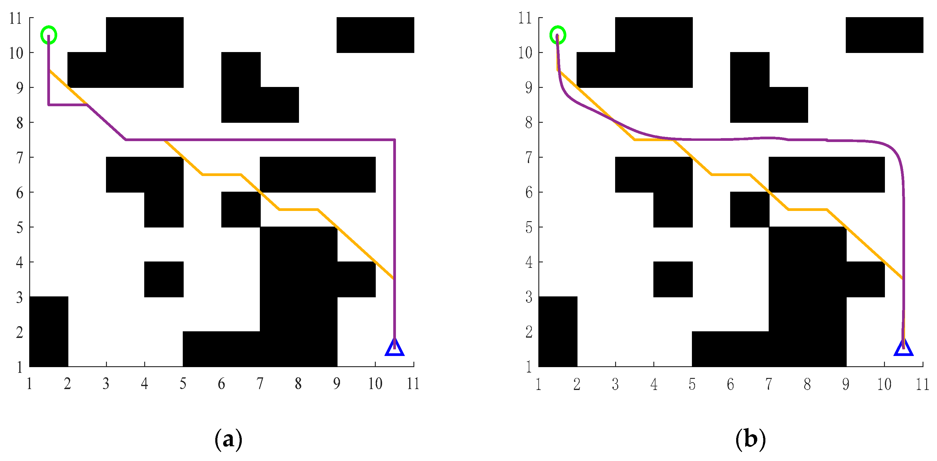
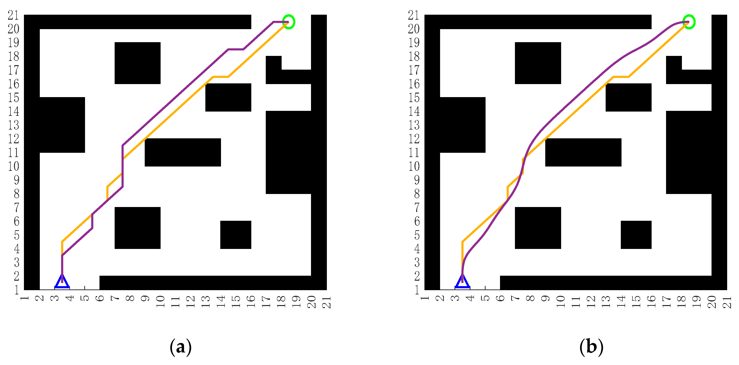
5.1. Improvement of A* Simulation

In this experiment, the traditional A* algorithm and the improved A* algorithm were employed to conduct path planning in raster environments of varying sizes. The planning results were then compared with the smooth paths generated based on Bezier curves. In the figures, the black areas denote obstacles, whereas the white or light-colored regions represent traversable spaces. Lines of different colors correspond to the paths generated by different algorithms or post-processing methods.
The first environment was a 10 × 10 raster map. With the starting point set at (1, 10), the end point at (10, 1), and an obstacle coverage rate of 22%, the path planning trajectory is depicted in Figure 4. The second environment was a 15 × 15 raster map, featuring a starting point at (15, 9), an end point at (2, 6), and an obstacle coverage rate of 30%. The corresponding path planning trajectory is illustrated in Figure 5. The third environment was a 20 × 20 raster map. The starting point was (18, 19), the end point was (3, 1), and the obstacle coverage rate was 35%. The path planning trajectory of this environment is shown in Figure 6.
Figure 4a, Figure 5a and Figure 6a show the path planning results of the traditional A* and improved A* algorithms in 10 × 10, 15 × 15, and 20 × 20 grid maps (traditional A* in yellow and improved A* in purple). As can be seen from the figure, the path generated by the traditional A* algorithm can reach the end point, but has a significant drawback: when planning paths in different raster maps, there are instances where the paths pass through the vertices of the obstacles (e.g., the vertices at (2, 9) and (5, 7) in Figure 4a), which causes the robot to operate with insufficient safety margins and makes it particularly prone to collision risks in narrow passages. In contrast, the improved A* algorithm effectively avoids obstacle vertices (e.g., the path maintains ≥1 grid distance from the nearest obstacle in Figure 5a) through adjustment of dynamic weight coefficients, reserving sufficient steering space for the robot and demonstrating better obstacle avoidance safety. However, due to the iterative computation of dynamic weights, the number of path-turning points of the improved A* algorithm increases significantly (e.g., the purple path in Figure 6a contains eight turning points), which may lead to discontinuous robot motion in closed environments and may even induce local oscillations. Figure 4b, Figure 5b and Figure 6b demonstrate the optimization effect of Bezier curves on the improved A* path. After secondary optimization, the sharp turns at the inflection points of the path are replaced by smooth curve transitions (e.g., the turns at (5, 5) and (7, 8) are obviously smoothed in Figure 6b), and the continuity of the robot motion trajectory is significantly improved. This demonstrates that the Bezier curve effectively mitigates path discontinuities caused by the obstacle avoidance strategy of the improved A* algorithm and provides a better trajectory basis for robot motion in complex environments.
Based on the data in Table 2, the traditional A* and improved A* algorithms exhibit notable disparities in path length and computational efficiency. In terms of path length, the traditional A* algorithm yields paths that are 20.23%, 3.65%, and 2.32% shorter than those of the improved A* algorithm in 10 × 10, 15 × 15, and 20 × 20 raster maps, respectively, reflecting its global optimality. As the map scale increases, however, the discrepancy in path length gradually narrows, indicating that the improved A* algorithm maintains a controlled increase in path length within reasonable limits for large-scale environments. Regarding computational efficiency, the improved A* algorithm incurs a time cost 2–3 times that of its traditional counterpart due to dynamic weight calculations and obstacle avoidance checks (e.g., 0.06 s for the improved algorithm vs. 0.02 s for the traditional algorithm in 10 × 10 maps). While computation time rises with increasing map complexity, it remains within the acceptable threshold for real-world engineering applications.
As shown in Table 3, the collision rate (CR)—a critical metric reflecting path collision probability (lower values indicate higher safety)—of the improved A* algorithm demonstrates superior performance across all grid sizes, particularly as obstacle coverage increases (22% for 10 × 10, 30% for 15 × 15, and 35% for 20 × 20 maps, signifying a gradual rise in environmental obstacle density). In the 10 × 10 map (lowest obstacle coverage), the CR drops from 45% to 30% (33.3% reduction); in the 15 × 15 map (moderate coverage), it decreases from 35% to 16% (54.3% decline); and in the 20 × 20 map (highest coverage, 35%), it falls from 22% to 11.76% (46.5% decrease). Notably, *even as obstacle density increases by 59.1% (from 22% to 35%), the improved algorithm sustains a consistent CR reduction (average 44.7% across all maps), whereas the traditional A shows a smaller average CR decrease of 23%. This highlights the improved algorithm’s robustness in high-obstacle environments; it not only reduces collision risks but also maintains stable safety performance as the environment becomes more cluttered (e.g., in urban or industrial settings with obstacle density). The Bezier curve optimization further enhances trajectory smoothness without sacrificing safety, even in scenarios with elevated obstacle coverage, reinforcing the algorithm’s adaptability to complex terrains.
Overall, the improved A* algorithm achieves substantial advancements in path safety and trajectory smoothness at the cost of a moderate increase in computation time. The Bezier curve optimization strategy further amplifies its comprehensive advantages in motion planning for complex environments, empirically verifying the effectiveness and practicality of the “DWA + Bezier curve smoothing” framework.
To further validate the adaptability of the algorithm in large-scale environments, supplementary simulations on a 45 × 45 grid map are conducted.
In the 45 × 45 complex grid simulation (Figure 7, Table 4), the algorithm in Reference [8] achieves a search time of 0.044 s but produces highly circuitous trajectories (path length: 56.21 m) because its evaluation function omits explicit obstacle information, instead relying on neighborhood searches and post-processing to eliminate detours (Figure 7c). By contrast, the improved algorithm presented here, despite a longer search time of 0.131 s, embeds obstacle distance penalties and dynamic weighting based on environmental complexity directly into the heuristic evaluation. As a result, the optimized path length is reduced to 51.04 m—a 9.2% improvement over Reference [8]—and generates smooth, direct trajectories without redundant detours (Figure 7d). The core distinction lies in Reference [8]’s post hoc obstacle avoidance logic, which cannot balance global path efficiency and local collision avoidance in real time under complex conditions. In contrast, our method pre-integrates obstacle constraints into the evaluation function, dynamically adjusting the priority between global exploration and local evasion to minimize unnecessary detours while ensuring collision-free navigation. The improved approach is particularly well suited to applications that demand both high path efficiency and robust safety, such as mobile charging robot navigation. Experimental observations indicate that the enhanced evaluation function performs effectively and remains adaptable in environments with complex obstacle layouts.

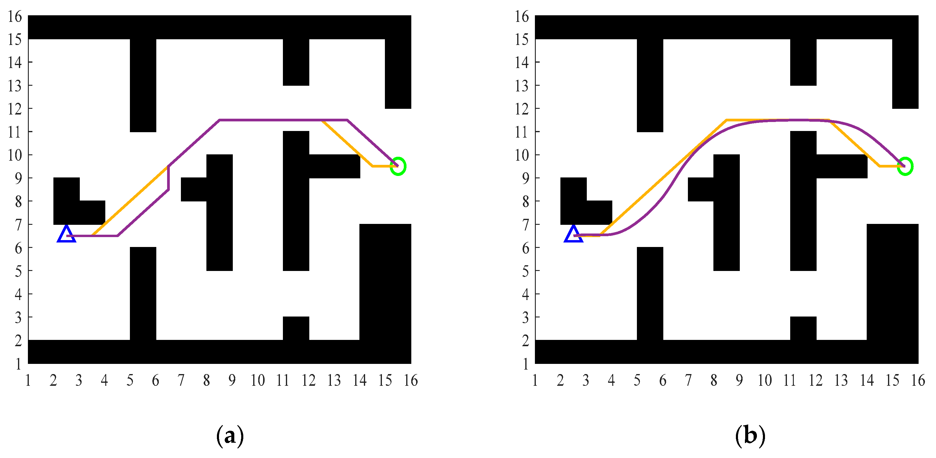
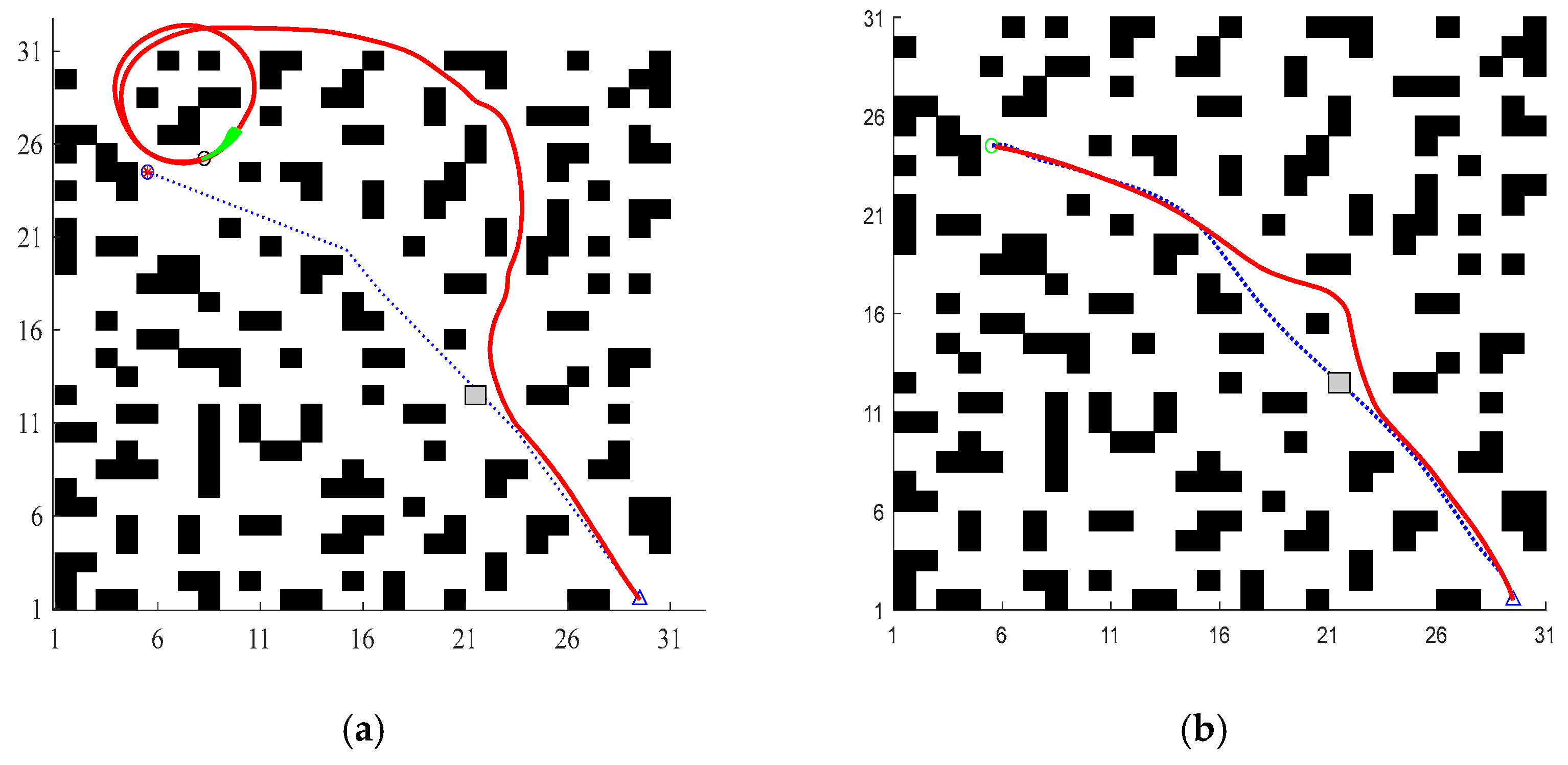
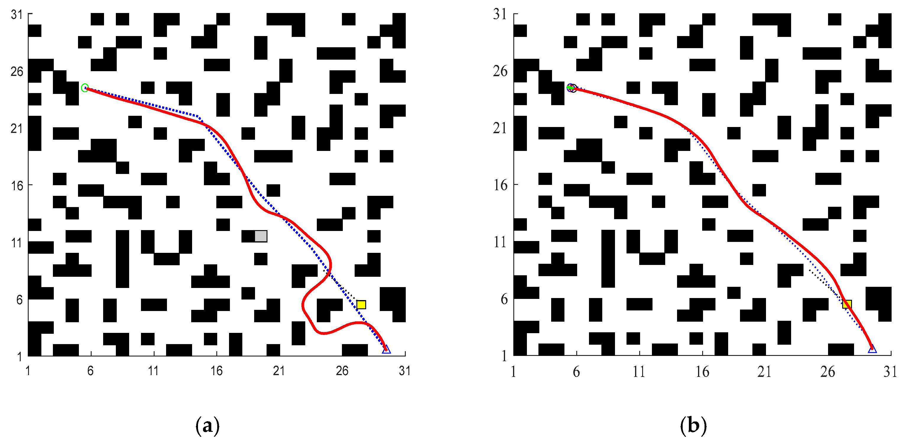
5.2. Fusion Algorithm Simulation

To verify the effectiveness of the improved evaluation function in the DWA algorithm, Figure 8 depicts the path planning for testing unknown obstacles, The dashed line denotes the global path planned by A*. The solid line signifies the final path of the fused DWA, the triangle marks the starting point, the circle indicates the end point, and the yellow square represents the moving obstacle.
For Figure 8, which illustrates obstacle avoidance for unknown obstacles, we can provide the following detailed analysis. In Figure 8a, the traditional DWA algorithm exhibits suboptimal performance when encountering unknown obstacles. The path planning appears lagging and less optimized, possibly resulting in detours or failure to maintain a safe distance from obstacles. This is attributed to the traditional algorithm’s limited ability to promptly and effectively integrate new obstacle information into its planning mechanism. In contrast, Figure 8b showcases the improved DWA algorithm. By virtue of the integrated global guidance mechanism and dynamic heading adjustment, it demonstrates enhanced responsiveness to unknown obstacles. The global guidance term provides a constant orientation towards the target, preventing the robot from deviating due to sudden unknown obstacles. Meanwhile, the dynamic adjustment of the heading weight coefficient ensures that after obstacle avoidance, the robot can quickly realign with the target -oriented direction. Consequently, the path is smoother, and the obstacle avoidance distance is more reasonable, minimizing unnecessary detours. This indicates that the improved algorithm has better adaptability to unknown environments, as the synergy of global guidance and dynamic heading adjustment enables more intelligent real-time path adjustment decision making.
Turning to Figure 9, which focuses on obstacle avoidance for moving obstacles, Figure 9a reveals that the traditional DWA algorithm struggles to cope with moving obstacles. The path planning shows fluctuations, and it fails to effectively track the target, primarily because the traditional algorithm lacks an efficient mechanism through which to predict the trajectory of moving obstacles. On the contrary, Figure 9b highlights the superiority of the improved DWA algorithm. Leveraging the improved evaluation function with global guidance and dynamic heading adjustment, it can better anticipate the trajectory of moving obstacles. The global guidance ensures continuous target tracking, preventing the robot from losing its way in dynamic scenarios.
According to the data in Table 5, in the test environment of moving obstacles, the path length of the traditional A*&DWA algorithm is 40.46 m, and the time consumption is 260.23 s. Meanwhile, for the improved A*&DWA algorithm, the path length is shortened to 34.88 s, and the time consumption is reduced to 178.48 s. It can be seen that the improved fusion algorithm reduces the path length by approximately 13.8% and shortens the time by approximately 31.4%. This indicates that the improved fusion algorithm not only optimizes path planning but also improves computational efficiency, demonstrating superior performance in the scenario of moving obstacles. It effectively verifies the feasibility and advantages of the improved fusion algorithm in practical applications.

6. Conclusions and Discussion

Traditional path planning methods face three key limitations: insufficient static path safety, poor real-time dynamic obstacle avoidance, and suboptimal smoothness. To overcome these challenges, this paper proposes a hybrid algorithm integrating enhanced A* and DWA.
  • By introducing an obstacle influence degree into the evaluation function and combining dynamic weight coefficients, the algorithm dynamically balances heuristic costs and obstacle avoidance requirements. This enables the robot to proactively avoid obstacle-dense areas during the search process, enhancing path safety in complex environments.
  • Discrete grid paths are smoothed using piecewise Bezier curve fitting, significantly reducing path inflection points and sharp turns. This approach satisfies robotic kinematic constraints, ensuring that trajectories are compatible with the robot’s motion capabilities and improving operational stability.
  • To tackle the target loss and local minimum issues in the DWA algorithm, a global guidance term and dynamic heading weight are integrated into the evaluation function. This strengthens the algorithm’s target orientation in dynamic environments, ensuring the robot maintains progress toward the goal while executing obstacle avoidance, thus overcoming the traditional DWA’s vulnerability to local optima.
Simulation results demonstrate that the improved algorithm achieves smooth path planning and effective obstacle avoidance across grid maps of varying scales, significantly alleviating issues such as collision risks and sharp turns in paths generated by traditional algorithms. The current research remains limited to validation on simulation platforms and has not undergone experimental testing on physical robots, where factors like sensor noise and localization errors in real-world scenarios may impact performance. Future work will focus on deploying and testing the proposed fused algorithm on physical robot platforms, with explicit consideration of sensor-related factors, in order to address real-world uncertainties; it will further evaluate the system’s robustness, real-time performance, and practical feasibility through experiments in actual environments.

Author Contributions

Conceptualization, Z.C.; Methodology, W.Z.; Validation, Z.C.; Formal analysis, W.Z.; Investigation, W.Z.; Resources, Z.C.; Data curation, Z.C.; Writing—original draft, Z.C.; Writing—review and editing, W.Z.; Funding acquisition, W.Z. All authors have read and agreed to the published version of the manuscript.

Funding

This research received no external funding.

Data Availability Statement

The original contributions presented in this study are included in the article. Further inquiries can be directed to the corresponding author.

Conflicts of Interest

The authors declare no conflicts of interest.

References

  1. Wang, H.; Sun, J.; Cheng, K.W.E. An Inductive Power Transfer system with multiple receivers utilizing Diverted Magnetic Field and two transmitters for IoT-level automatic catering vehicles. IEEE Trans. Magn. 2023, 59, 1–6. [Google Scholar]
  2. Ye, W. The current situation and future trends of new energy vehicles. Auto Time 2024, 19, 128–130. [Google Scholar]
  3. Karur, K.; Sharma, N.; Dharmatti, C.; Siegel, J.E. A survey of path planning algorithms for mobile robots. Vehicles 2021, 3, 448–468. [Google Scholar] [CrossRef]
  4. Rachmawati, D.; Gustin, L. Analysis of Dijkstra’s Algorithm and A* Algorithm in Shortest Path Problem. In Proceedings of the 4th International Conference on Computing and Applied Informatics 2019 (ICCAI 2019), Medan, Indonesia, 26–27 November 2019. [Google Scholar]
  5. Han, Z.; Sun, H.; Huang, J.; Xu, J.; Tang, Y.; Liu, X. Path planning algorithms for smart parking: Review and prospects. World Electr. Veh. J. 2024, 15, 322. [Google Scholar] [CrossRef]
  6. Liu, L.; Wang, X.; Yang, X.; Liu, H.; Li, J.; Wang, P. Path planning techniques for mobile robots: Review and prospect. Expert Syst. Appl. 2023, 227, 120254. [Google Scholar] [CrossRef]
  7. Bai, J.; Bai, Y.; Xi, J.; Zhang, J. Workshop Material Distribution Path Planning Based on Improved A* Algorithm. J. Jilin Univ. Sci. Ed. 2024, 62, 1401–1410. [Google Scholar]
  8. Erke, S.; Bin, D.; Yiming, N.; Qi, Z.; Liang, X.; Dawei, Z. An improved A-Star based path planning algorithm for autonomous land vehicles. Int. J. Adv. Robot. Syst. 2020, 17, 1729881420962263. [Google Scholar] [CrossRef]
  9. Qi, K.; Li, E.; Mao, Y. Dynamic Path Planning of Mobile Robot Based on Improved A* Algorithm and Adaptive DWA. Data Acquis. Process. 2023, 38, 451–467. [Google Scholar]
  10. Liu, L.; Wang, B.; Xu, H. Research on Path-Planning Algorithm Integrating Optimization A-Star Algorithm and Artificial Potential Field Method. Electronics 2022, 11, 3660. [Google Scholar] [CrossRef]
  11. Wang, Z.; Zeng, G.; Huang, B.; Fang, Z. Global Optimal Path Planning for Robots Based on Improved A* Algorithm. J. Comput. Appl. 2019, 39, 2517. [Google Scholar]
  12. Li, X.; Miao, M.; Ran, B.; Zhao, Y.; Zhao, Y.; Li, G. UAV Obstacle Avoidance Path Planning Based on Improved A* Algorithm. Comput. Syst. Appl. 2021, 30, 255–259. [Google Scholar]
  13. Qi, F.; Wang, X.; Zhang, G. Obstacle avoidance path planning for AGV based on improved A* algorithm. Mach. Tool Hydraul. 2023, 51, 34–39. [Google Scholar]
  14. Jia, L.; Zeng, S.; Feng, L.; Lv, B.; Yu, Z.; Huang, Y. Global time-varying path planning method based on tunable Bezier curves. Appl. Sci. 2023, 13, 13334. [Google Scholar] [CrossRef]
  15. Liu, H.; Zhang, Y. ASL-DWA: An improved A-star algorithm for indoor cleaning robots. IEEE Access 2022, 10, 99498–99515. [Google Scholar] [CrossRef]
  16. Cheng, C.; Sha, Q.; He, B.; Li, G. Path planning and obstacle avoidance for AUV: A review. Ocean Eng. 2021, 235, 109355. [Google Scholar] [CrossRef]
  17. Wang, H.; Hao, C.; Zhang, P.; Zhang, M.; Yin, P.; Zhang, Y. Path Planning of Mobile Robots Based on A* Algorithm and Artificial Potential Field Algorithm. China Mech. Eng. 2019, 30, 2489–2496. [Google Scholar]
  18. Liu, W.; Xu, C.; Zhang, Q.; Wan, Y. Trajectory planning of tire laser engraving orthogonal robot based on an improved multi-objective grasshopper optimization algorithm. Proc. Inst. Mech. Eng. Part C J. Mech. Eng. Sci. 2024, 238, 5851–5864. [Google Scholar] [CrossRef]
  19. Jiang, H.; Wu, T.; Ren, J.; Li, M.; Xiong, A.; Jia, J. Local Path Planning for Mobile Robots Based on Improved DWA Algorithm. Mach. Des. Res. 2024, 40, 229–234. [Google Scholar]
  20. Lin, Z.; Yue, M.; Chen, G.; Sun, J. Path planning of mobile robot with PSO-based APF and fuzzy-based DWA subject to moving obstacles. Trans. Inst. Meas. Control 2022, 44, 121–132. [Google Scholar] [CrossRef]
  21. Yang, H.; Teng, X. Mobile robot path planning based on enhanced dynamic window approach and improved A∗ algorithm. J. Robot. 2022, 1, 2183229. [Google Scholar] [CrossRef]
  22. Wang, Y.; Li, J.; Zhao, S.; Su, P.; Fu, H.; Niu, H. Hybrid path planning for USV with kinematic constraints and COLREGS based on improved APF-RRT and DWA. Ocean Eng. 2025, 318, 120128. [Google Scholar] [CrossRef]
Figure 1. Mobile charging robot.
Electronics 14 02318 g001
Figure 2. Simulation results of different evaluation functions. (a) Reference [8] algorithm. (b) Traditional algorithm. (c) Improved algorithm.
Electronics 14 02318 g002
Figure 3. Flowchart of the fusion algorithm.
Electronics 14 02318 g003
Figure 4. A 10 × 10 grid map (obstacle coverage rate: 22%). (a) Traditional A* algorithm vs. improved evaluation function A* algorithm. (b) Bezier curve optimization based on improved A* algorithm for path smoothing.
Electronics 14 02318 g004
Figure 5. A 15 × 15 grid map (obstacle coverage rate: 30%). (a) Traditional A* algorithm vs. improved evaluation function A* algorithm. (b) Bezier curve optimization based on improved A* algorithm for path smoothing.
Electronics 14 02318 g005
Figure 6. A 20 × 20 grid map (obstacle coverage rate: 35%). (a) Traditional A* algorithm vs. improved evaluation function A* algorithm. (b) Bezier curve optimization based on improved A* algorithm for path smoothing.
Electronics 14 02318 g006
Figure 7. Path planning results on a 45 × 45 grid map. (a) Traditional A* algorithm. (b) Improved A* algorithm. (c) Improved A* algorithm from Reference [8]. (d) Path optimized by Bezier curve smoothing.
Electronics 14 02318 g007
Figure 8. Obstacle avoidance for unknown obstacles. (a) Traditional DWA algorithm. (b) Improvement of the evaluation function DWA algorithm.
Electronics 14 02318 g008
Figure 9. Obstacle avoidance for moving obstacles. (a) Traditional DWA algorithm. (b) Improvement of the evaluation function DWA algorithm.
Electronics 14 02318 g009
Table 1. Simulation comparison of different evaluation functions.
Evaluation
Function
Search
Time (s)
Path
Length (m)
Searched NodesMinimum Safe
Distance (m)
Collision
Rate (%)
Reference [8]0.03327.3872037.5%
Traditional0.01825.97126030%
Improved0.02528.311060.510%
Table 2. Comparison of A* algorithm improvement before and after in multi-grid maps.
10 × 10 Grid Map15 × 15 Grid Map20 × 20 Grid Map
Length (m)Time (s)Length (m)Time (s)Length (m)Time (s)
Traditional14.480.0215.90.0225.380.03
Improved17.410.0616.480.0725.970.07
Bezier curve16.40.0715.760.0824.810.08
Table 3. Collision rate comparison.
Algorithm10 × 10 Grid
Map CR (%)
15 × 15 Grid
Map CR (%)
20 × 20 Grid
Map CR (%)
Traditional45%35%22%
Improved30%16%11.76%
Table 4. Comparison of performance of different algorithms.
AlgorithmSearch
Time (s)
Path
Length (m)
CR (%)
Traditional0.04746.947.89%
Reference [8]0.04456.2127.45%
Improved0.13151.040%
Bezier curve-48.69-
Table 5. Comparison of algorithms before and after improvement.
Length (m)Time (s)
Traditional A*&DWA40.46260.23
Improved A*&DWA34.88178.48
Disclaimer/Publisher’s Note: The statements, opinions and data contained in all publications are solely those of the individual author(s) and contributor(s) and not of MDPI and/or the editor(s). MDPI and/or the editor(s) disclaim responsibility for any injury to people or property resulting from any ideas, methods, instructions or products referred to in the content.

