
A Compact Triple Band Antenna Based on Multiple Split-Ring Resonators for Wireless Applications


Abstract
1. Introduction
2. Construction of the Proposed Multi-SRR-Based Antenna
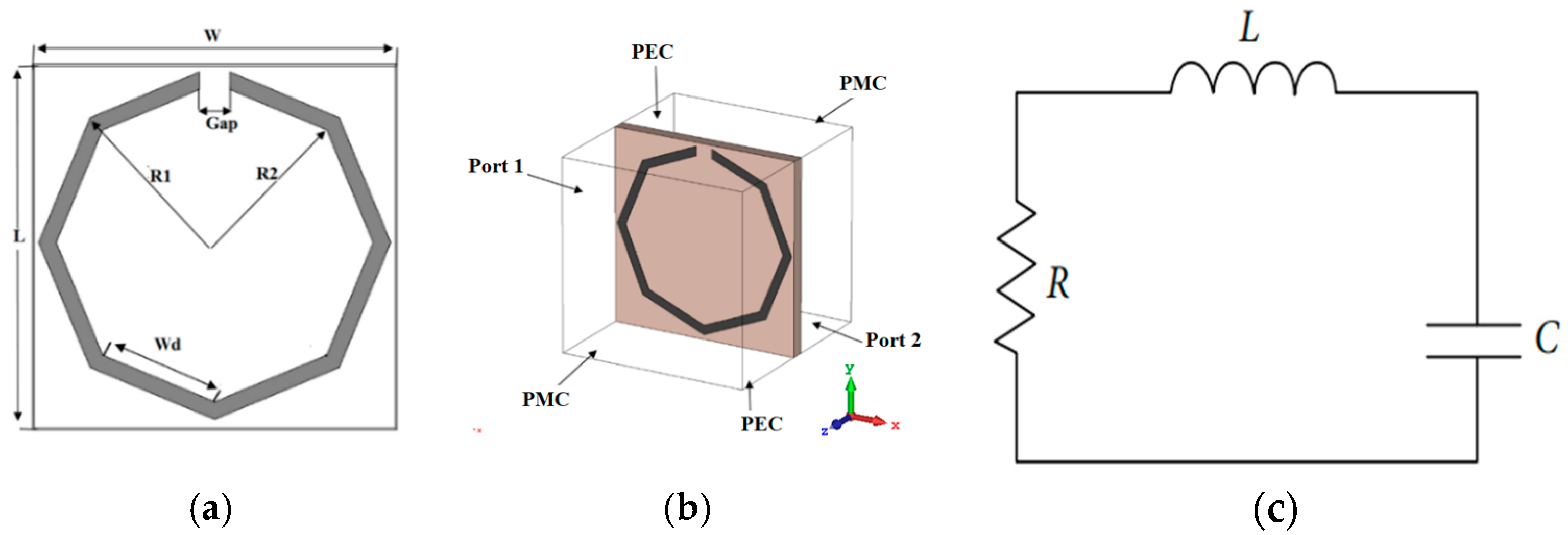
2.1. Split-Ring Resonator Unit Cell Design
- -
- Inductance (L): Represents the self-inductance of the SRR loop, which is related to the size and shape of the ring.
- -
- Capacitance (C): Corresponds to the gap of the SRR.
- -
- Resistance (R): Represents the total ohmic losses in the metallic structure, as well as dielectric losses in the substrate material.
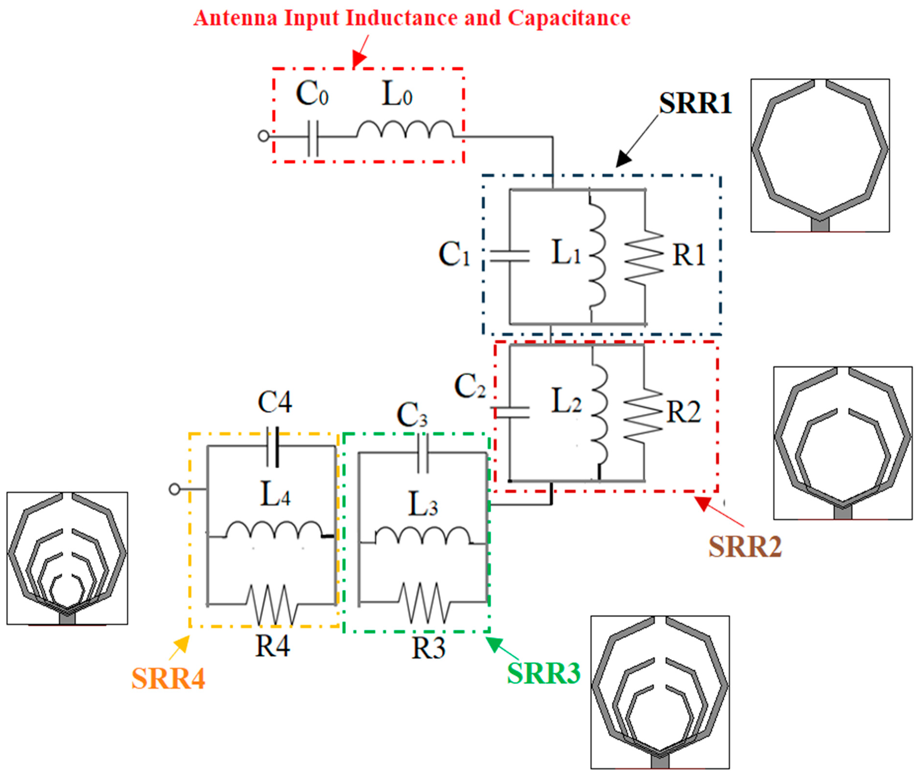
2.2. Split-Ring Resonators Loaded Antenna
2.3. Modeling and Analysis of the Equivalent Circuit for SRR-Based Antenna
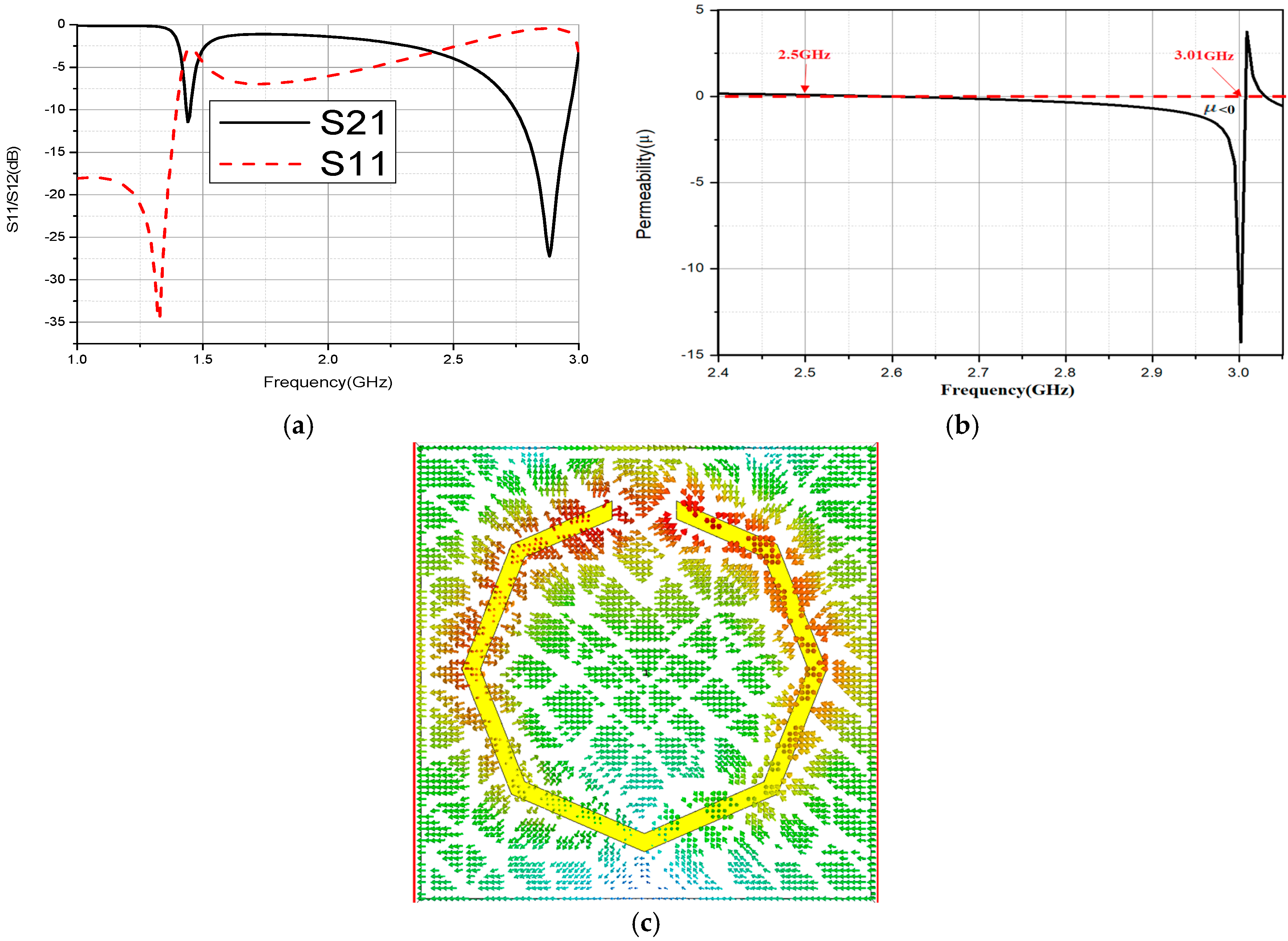
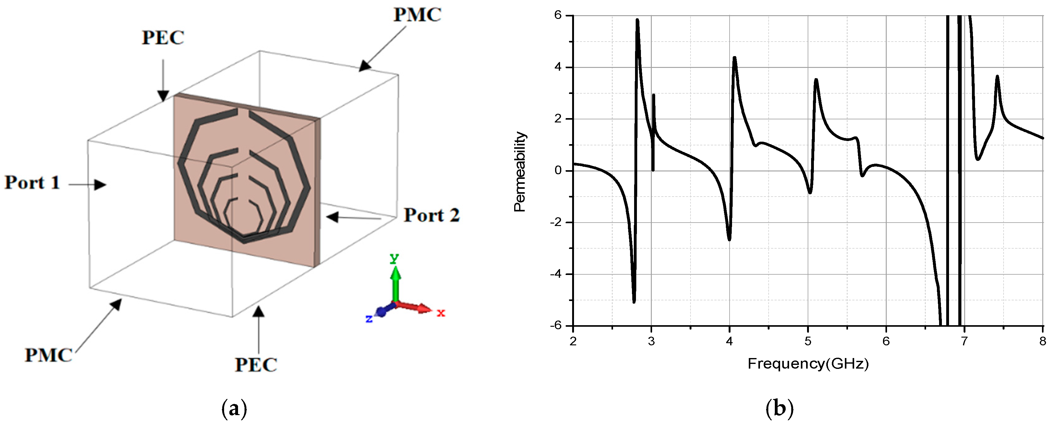
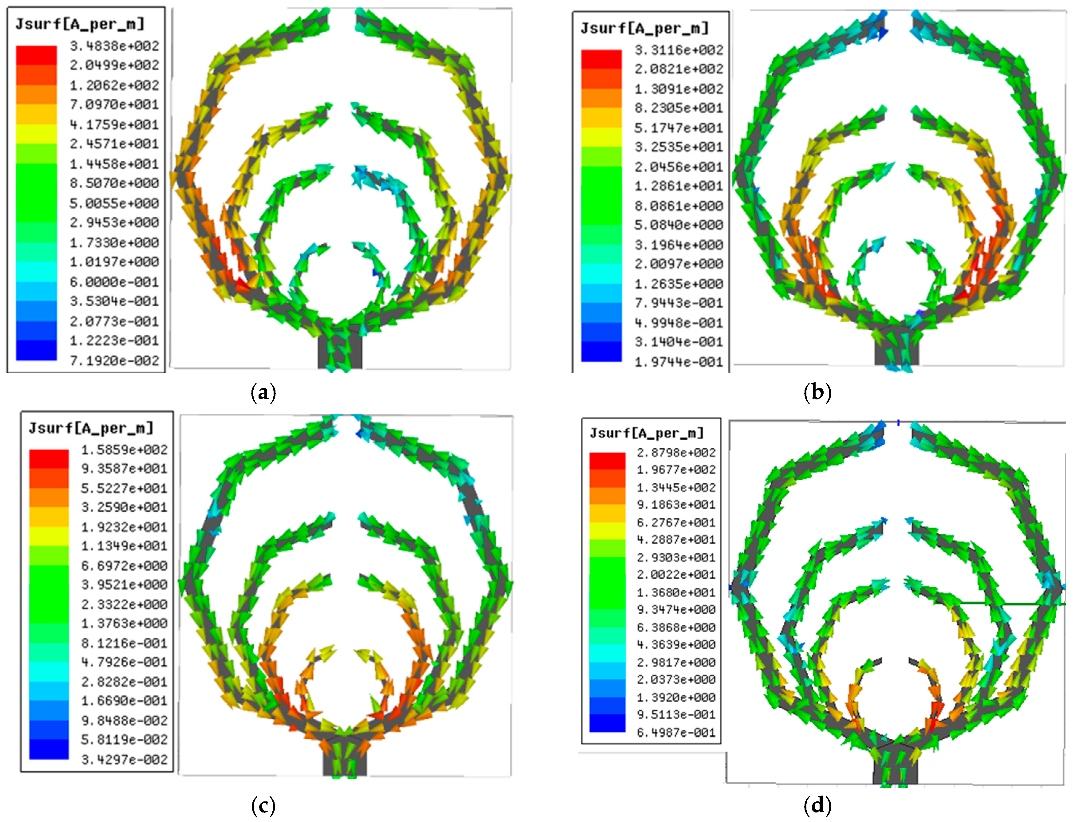
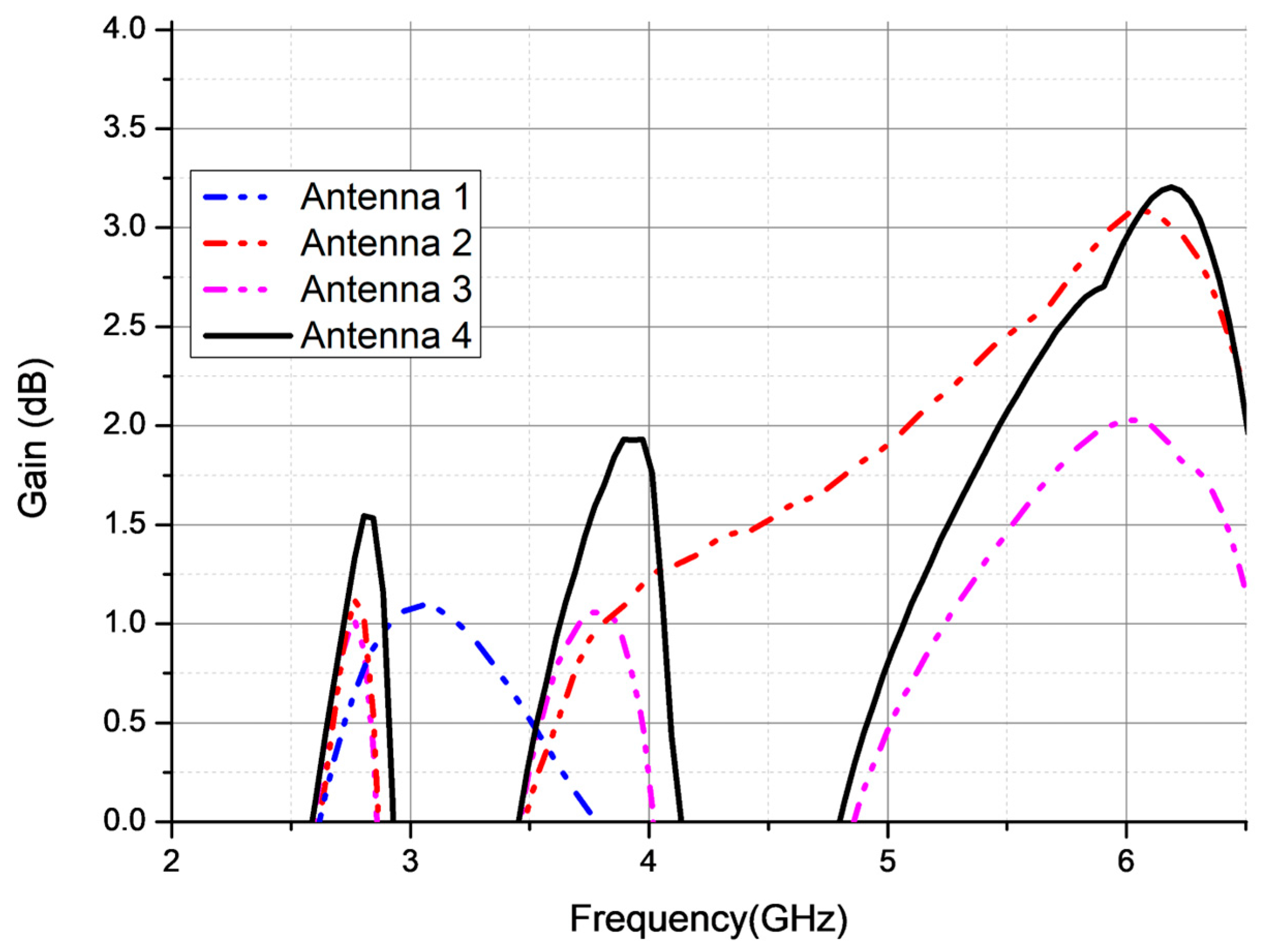
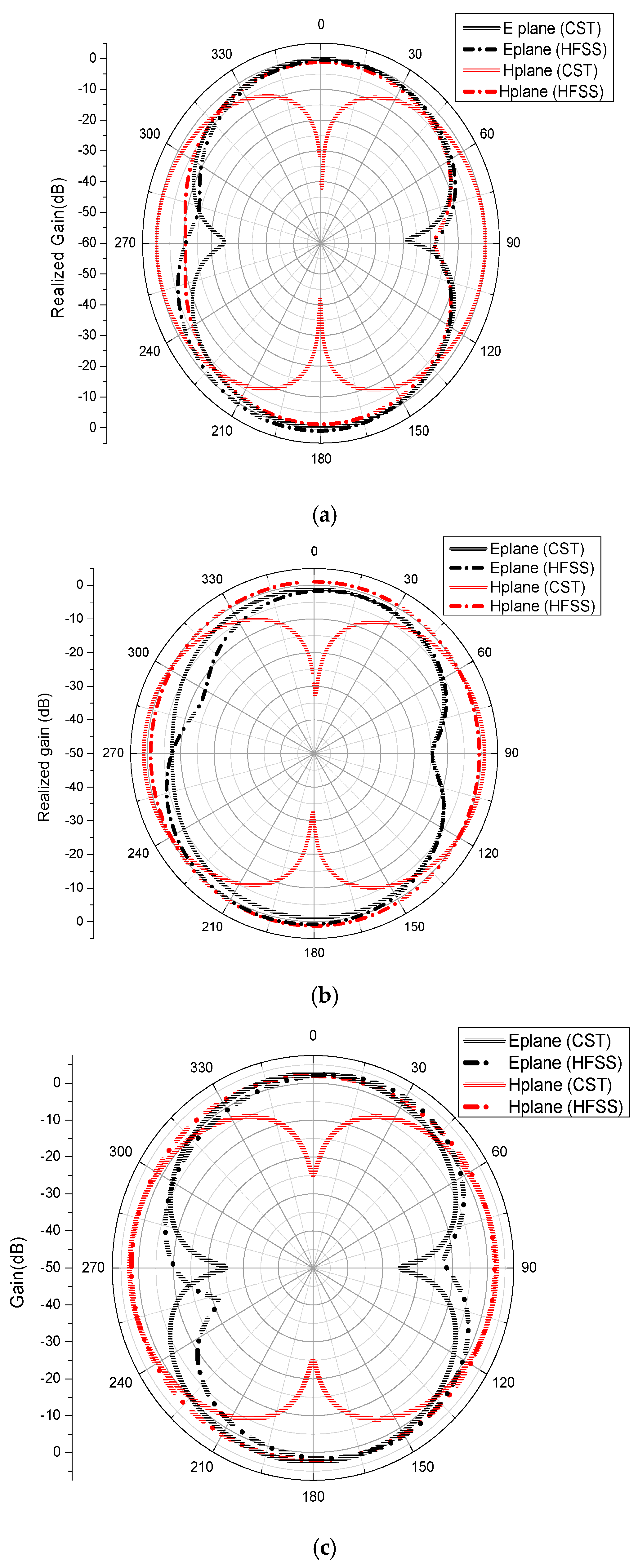
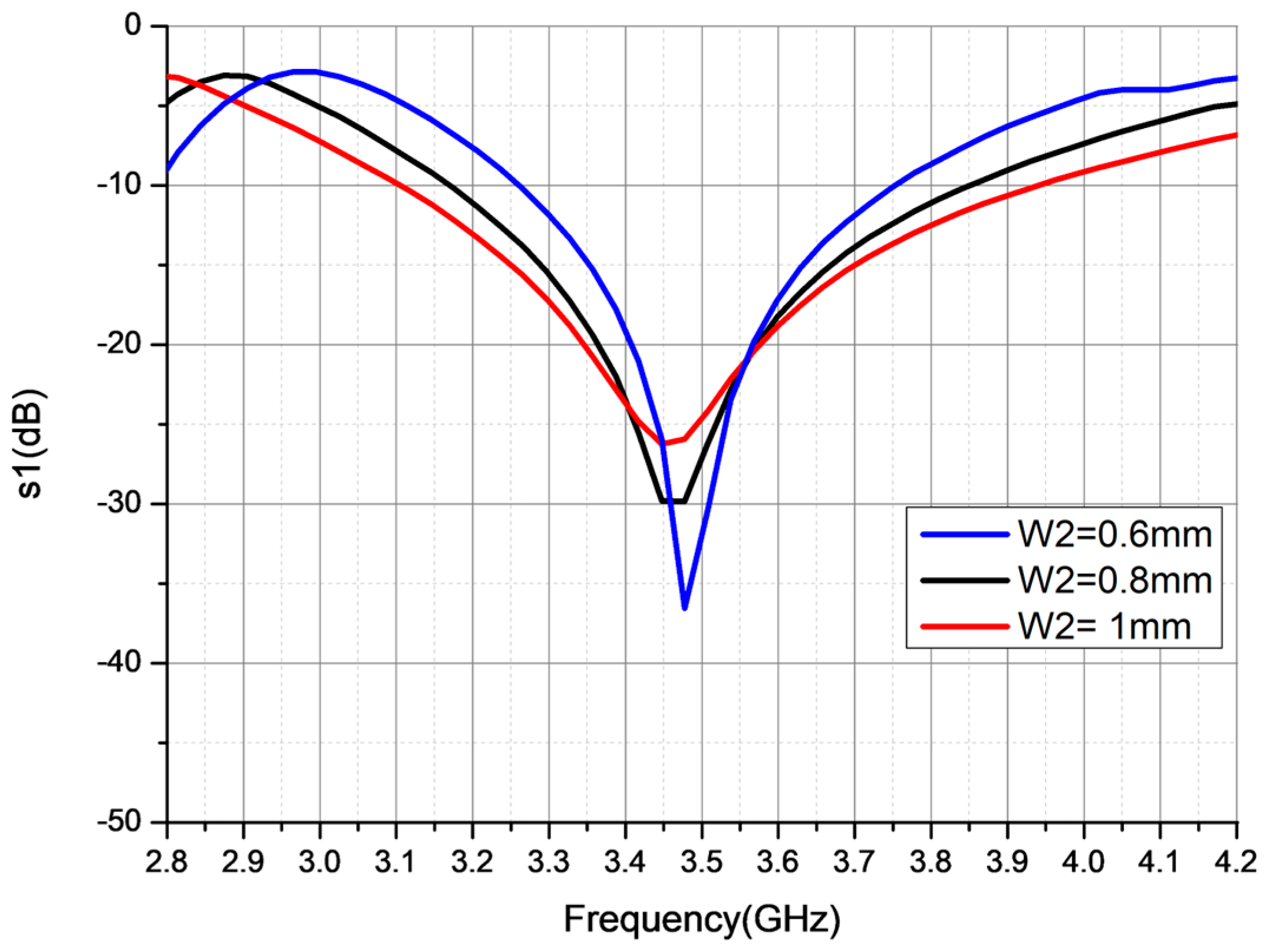
3. Results and Discussion
- -
- Method 1 models the split-ring resonator as a resonant ring, where the effective electrical length is proportional to the physical circumference. The resonance frequency is calculated using the following expression:
- -
- Method 2 treats the arms of the SRR as equivalent dipole antennas with an effective length LSRRn, leading to the resonance frequencywhereAs an illustrative example, for SRR1, the total effective length is given byLSRR1 = Wn+ Lf+ L11 + L12 + L13 + L14 = 35.45 mm
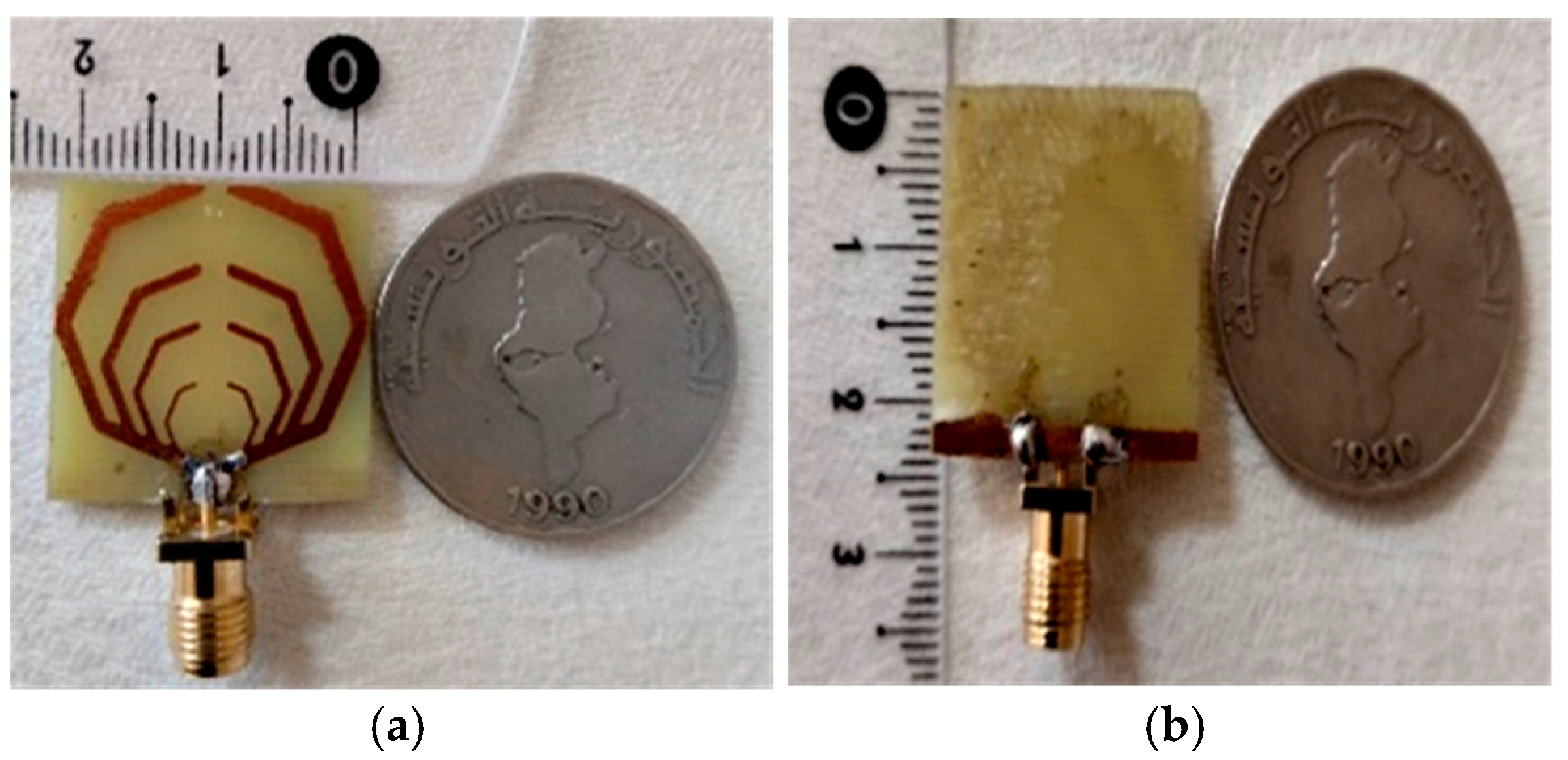
4. Fabrication and Measurement
5. Comparative Study
6. Conclusions
Author Contributions
Funding
Data Availability Statement
Acknowledgments
Conflicts of Interest
Abbreviations
| ADS | Advanced Design System |
| BW | Bandwidth |
| CST | Computer Simulation Technology |
| FBW | Fractional Bandwidth |
| HFSS | High-Frequency Structure Simulator |
| MTM | Metamaterial |
| RFID | Radio Frequency Identification |
| SRR | Split-ring Resonator |
| VNA | Vector Network Analyzer |
| VSWR | Voltage Standing Wave Ratio |
| Wi-Fi | Wireless Fidelity |
| WiMAX | World Interoperability for Microwave Access |
| WLAN | Wireless Local Area Network |
References
- Azizi, S.; Naderi, M.; Hatami, A.; Zarrabi, F.B. Microstrip slot antenna as an indoor wireless RFID with multiband attributes based on composite right-hand/left-hand load. Microw. Opt. Technol. Lett. 2020, 62, 184–192. [Google Scholar] [CrossRef]
- Wang, L.; Yu, J.; Xie, T.; Bi, K. A novel multiband fractal antenna for wireless application. Int. J. Antennas Propag. 2021, 1–9. [Google Scholar] [CrossRef]
- Sung, Y. Wideband circularly polarized antenna for dual-band operation. Microw. Opt. Technol. Lett. 2021, 63, 286–294. [Google Scholar] [CrossRef]
- Kodali, R.R.; Siddaiah, P.; Giri Prasad, M.N. Arrow cross shape slotted fractal antenna with enhanced bandwidth for Wi-Fi/WiMAX/WLAN applications. Prog. Electromagn. Res. C 2022, 119, 115–124. [Google Scholar] [CrossRef]
- Kumari, S.; Awasthi, Y.K.; Bansal, D. Proposed multiband fractal monopole antenna for WLAN and WiMAX applications. Prog. Electromagn. Res. C 2022, 127, 239–249. [Google Scholar] [CrossRef]
- Nallapaneni, S.; Muthusamy, P. Design of multiband fractal antenna loaded with parasitic elements for gain enhancement. Int. J. RF Microw. Comput. Aided Eng. 2021, 31, e22622. [Google Scholar] [CrossRef]
- Zhang, K.; Yan, S. Compact omnidirectional dual-band dipole antenna with reduced ground plane effect. Microw. Opt. Technol. Lett. 2021, 63, 1753–1759. [Google Scholar] [CrossRef]
- Yu, Z.; Lin, Z.; Ran, X.; Li, Y.; Liang, B.; Wang, X. A novel pane structure multiband microstrip antenna for 2G/3G/4G/5G/WLAN/navigation applications. Int. J. Antennas Propag. 2021, 2021, 1–15. [Google Scholar] [CrossRef]
- Xu, Y.; Zhang, Z.; Wang, A.; Hou, J. Design of three multibranch microstrip antennas compatible with WiMAX/WiFi/4G/5G NR for coal mine applications. Microw. Opt. Technol. Lett. 2023, 65, 892–900. [Google Scholar] [CrossRef]
- Fu, S.; Zhao, X.; Li, C.; Wang, Z. Dual-band and omnidirectional miniaturized planar composite dipole antenna for WLAN applications. Int. J. RF Microw. Comput. Aided Eng. 2021, 31, e22863. [Google Scholar] [CrossRef]
- Malathy, E.M.; Thanikachalam, V.; Ruby, D.; Manikandan, N. Metamaterial-loaded multiband antenna for embedded automotive Internet-of-Things communications. Int. J. Commun. Syst. 2021, 34, e4941. [Google Scholar] [CrossRef]
- Banting, H.A.; Saavedra, C.E. Bandwidth Enhancement of Low-Profile Metasurface Antenna Using Nonuniform Geometries. IEEE Open J. Antennas Propag. 2023, 4, 581–587. [Google Scholar] [CrossRef]
- Anelli, F.; Loconsole, A.M.; Francione, V.V.; Khan, M.I.; Prudenzano, F. Cost-effective Fabry-Pérot Antenna via Conductive Inkjet and Additive Printing. IEEE Antennas Wirel. Propag. Lett. 2025, 1–5. [Google Scholar] [CrossRef]
- Rammyaa, B.; Vishvaksenan, K.S. CPW fed metamaterial loaded dual-band roof-top antenna for vehicular communications. Int. J. RF Microw. Comput. Aided Eng. 2021, 31, e22740. [Google Scholar] [CrossRef]
- Rajanna, V.K.S.; Venkatesh, T.; Rajanna, P.K.T.; Shambulinga, M. A triband slot antenna loaded with asymmetric split ring resonator for wireless applications. Prog. Electromagn. Res. Lett. 2024, 117, 61–67. [Google Scholar] [CrossRef]
- Joe, D.A.; Krishnan, T. A triband compact antenna for wireless applications. Int. J. Antennas Propag. 2023. [Google Scholar] [CrossRef]
- Khadar, S.A.; Sahu, S. Compact metamaterial loaded wideband monopole antenna for wireless applications. Prog. Electromagn. Res. C 2023, 128, 247–261. [Google Scholar] [CrossRef]
- Abdalla, M.A.; El Atrash, M.; El-Sobky, N.A.; Zahran, S.R. Concept and analysis of a coupled split-ring resonator for wide-/dual bands, self-filtering, high out-of-band suppression and highly efficient antennas. Int. J. Microw. Wirel. Technol. 2021, 13, 126–136. [Google Scholar] [CrossRef]
- Noor, S.K.; Jusoh, M.; Sabapathy, T.; Rambe, A.H.; Vettikalladi, H.; MAlbishi, A.; Himdi, M. A Patch Antenna with Enhanced Gain and Bandwidth for Sub-6 GHz and Sub-7 GHz 5G Wireless Applications. Electronics 2023, 12, 2555. [Google Scholar] [CrossRef]
- Rana, M.S.; Sen, B.K.; Mamun, M.T.-A.; Mahmud, M.S.; Rahman, M.M. A 2.45 GHz microstrip patch antenna design, simulation, and anlaysis for wireless applications. Bull. Electr. Eng. Inform. 2023, 12, 2173–2184. [Google Scholar] [CrossRef]
- Abdelkarim, M.; Gharsallah, A.; Faouel, R. Analysis and design of a high gain multiband antenna based on metamaterials for RFID applications. Int. J. RF Microw. Comput. Aided Eng. 2024. [Google Scholar] [CrossRef]
- Ez-zaki, F.; Belaid, K.A.; Ahmad, S.; Belahrach, H.; Ghammaz, A.; Al-Gburi, A.J.A.; Parchin, N.O. Circuit Modelling of Broadband Antenna Using Vector Fitting and Foster Form Approaches for IoT Applications. Electronics 2022, 11, 3724. [Google Scholar] [CrossRef]
- Caratelli, D.; Cicchetti, R.; Bit-Babik, G.; Faraone, A. Circuit Model and Near-Field Behavior of a Novel Patch Antenna for Wwlan Applications. Microw. Opt. Technol. Lett. 2007, 49, 97–100. [Google Scholar] [CrossRef]
- Ma, T.-G.; Hua, R.-C.; Chou, C.-F. Design of a Multiresonator Loaded Band-Rejected Ultrawideband Planar Monopole Antenna With Controllable Notched Bandwidth. IEEE Trans. Antennas Propag. 2008, 56, 2875–2883. [Google Scholar] [CrossRef]


| Ws | Wf | R3 | R4 | Wn | Wt | Wm | R8 | R5 |
|---|---|---|---|---|---|---|---|---|
| 23 | 3 | 7.94 | 7.14 | 1.42 | 2.43 | 1.33 | 3.06 | 5.67 |
| Ls | Lf | Lm | Lp | Wr | Lt | R7 | Ground | R6 |
| 24 | 2.5 | 5.84 | 4.17 | 0.83 | 2.5 | 3.4 | 1.6 | 5.10 |
| SRR | Radius (mm) | Length (mm) | Equivalent Circuit Parameters | fr (GHz) Analytical (Method 1) | fr (GHz) Analytical (Method 2) | fr (GHz) ADS Circuit | fr (GHz) CST Simulation |
|---|---|---|---|---|---|---|---|
| 1 | 11.22 | 35.45 | C0 = 0.21 pF, L0 = 4.2 nH, C1 = 3.06 pF, L1 = 1.17 nH, R1 = 790 Ω | 2.55 GHz | 2.58 GHz | 2.65 | 2.65 |
| 2 | 7.94 | 26.13 | C2 = 3.74 pF, L2 = 0.52 nH, R2 = 500 Ω | 3.53 GHz | 3.50 GHz | 3.60 | 3.50 |
| 3 | 5.67 | 19.70 | C3 = 0.70 pF, L3 = 1.25 nH, R3 = 1 Ω | 4.90 GHz | 4.80 GHz | 4.84 | 4.83 |
| 4 | 3.40 | 12.90 | C4 = 0.70 pF, L4 = 0.995 nH, R4 = 84 Ω | 7.40 GHz | 7.06 GHz | 6.03 | 6.80 |
| Antennas | No. of Band | Frequency Band (GHz) | fr (GHz) | Bandwidth in % | Peak Gain (dBi) | Directivity (dBi) | Efficiency % |
|---|---|---|---|---|---|---|---|
| Reference patch antenna | Band 1 | 2.47–2.53 | 2.5 | 2.41 | 1.88 | 6.35 | 35.7 |
| Antenna 1 | Band 1 | 2.35–3 | 2.69 | 24.34 | 1.1 | 3.12 | 62.8 |
| Antenna 2 | Band 1 | 2.4–2.8 | 2.68 | 15.38 | 1.1 | 3.14 | 62.5 |
| Band 2 | 3.25–4.25 | 3.55 | 26.66 | 1.1 | 3.08 | 63.5 | |
| Antenna 3 | Band 1 | 2.4–2.77 | 3.66 | 14.34 | 1.1 | 3.12 | 62.8 |
| Band 2 | 3.25–3.77 | 3.49 | 15.56 | 1.2 | 3.26 | 62.2 | |
| Band 3 | 4.5–6.47 | 4.9/5.8 | 35.94 | 2.02 | 3.56 | 70.3 | |
| Antenna 4 (Proposed antenna) | Band 1 | 2.4–2.80 | 2.65 | 14.55 | 1.5 | 3.11 | 69.1 |
| Band 2 | 3.25–3.75 | 3.47 | 14.28 | 2 | 3.2 | 75.9 | |
| Band 3 | 4.5–7.84 | 4.8/6.6 | 54.13 | 3.1 | 4.52 | 72.1 |
| Parameter (mm) | Frequency Band (GHz) | Max Return Loss (dB) | Fr (GHz) | Bandwidth in % |
|---|---|---|---|---|
| W2 = 0.6 | 3.25–3.75 | −37 | 3.48 | 14.28 |
| W2 = 0.8 | 3.17–3.85 | −30 | 3.46 | 19.37 |
| W2 = 1 | 3.1–3.95 | −26 | 3.45 | 24.11 |
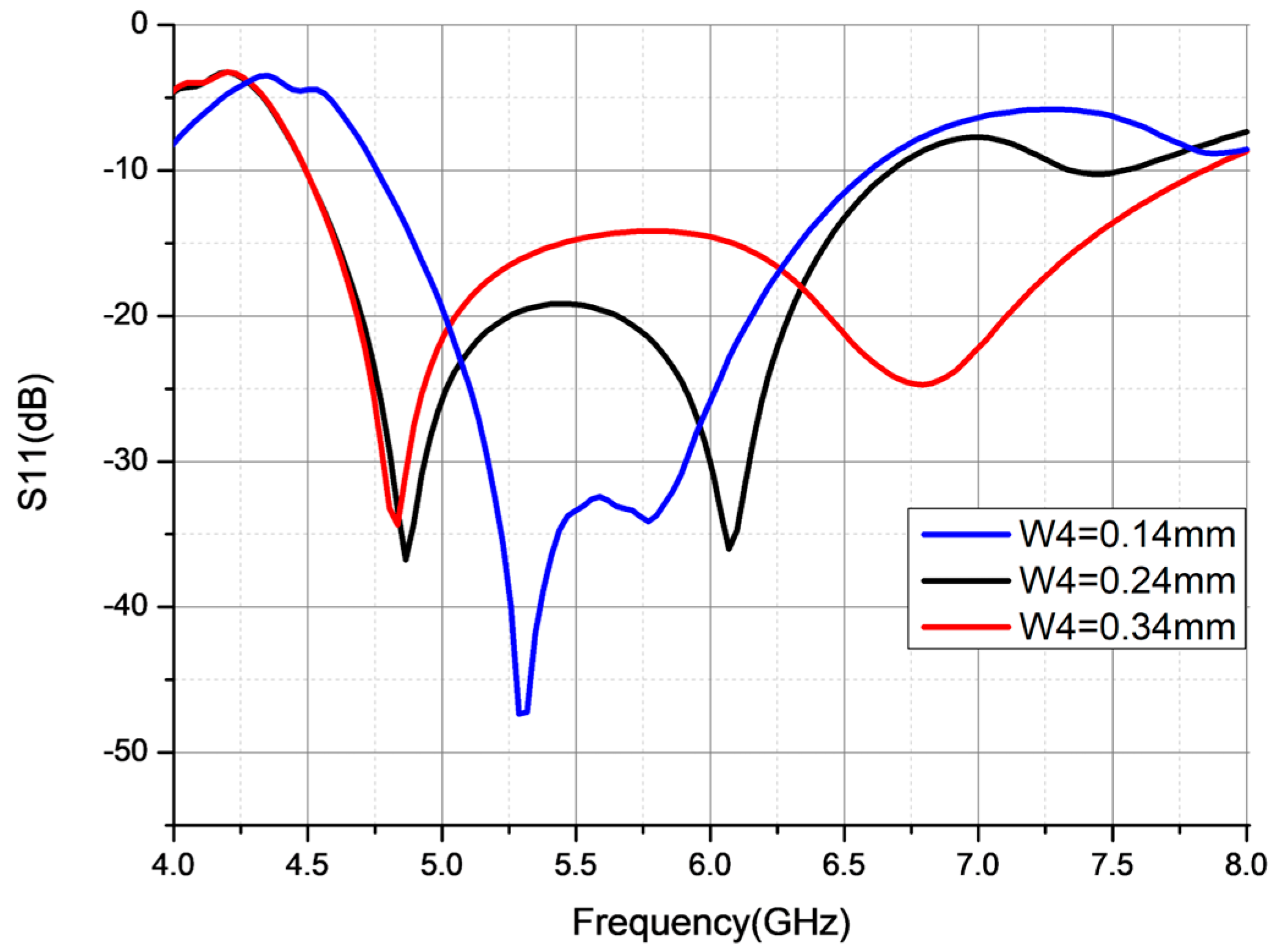
| Parameter (mm) | Frequency Band (GHz) | Max Return Loss (dB) | Fr (GHz) | Bandwidth in % |
|---|---|---|---|---|
| W4 = 0.14 | 4.75–6.5 | −45 | 5.3 | 26.43 |
| W4 = 0.24 | 4.5–6.75 | −37/−36 | 4.78/6.1 | 40.03 |
| W2 = 0.34 | 4.5–7.84 | −34/25 | 4.8 /6.8 | 54.13 |
| Parameter | Conventional Patch Antenna | Proposed Antenna | Trade-Off Analysis |
|---|---|---|---|
| Antenna dimension (mm³) | 60 × 50 × 1.6 | 23 × 24 × 1.6 | Significant size reduction |
| Electrical size (λ3) | 0.5 × 0.4 × 0.01 | 0.19 × 0.2 × 0.01 | |
| Miniaturization in (%) | - | 81.6 | Achieved via proposed Multi SRR technique |
| Operating Frequency (GHz) | 2.5 | 2.5, 3.5, 4.5−7.84 | Multiband functionality |
| Bandwidth in (%) | 2.41 | 14.55, 14.28, 54.13 | Improved bandwidth in all bands |
| Peak Gain in (dBi) | 1.87 | 1.5/2/3.1 | Slightly reduced gain |
| Directivity (dBi) | 6.35 | 3.11, 3.2, 4.52 | Significant reduced directivity |
| Radiation efficiency in (%) | 37.7 | 69.1, 75.9, 72.1 | Higher radiation efficiency despite FR4 losses |
| Band No. | Bandwidth (Simulation) | Bandwidth (Measurement) | Covered Bands |
|---|---|---|---|
| 1 | 2.4–2.80 GHz (14.55%) | 2.25–2.85 GHz (23.5%) | WLAN, RFID, Wi-Fi 6 (802.11ax) (2.4–2.48 GHz), 5G Sub-6 GHz Mid-band (2.5–2.6 GHz), WiMAX (2.3–2.5 GHz), Wi-Fi 7 |
| 2 | 3.25–3.75 GHz (14.28%) | 3.35–4.05 GHz (18.9%) | 5G Sub-6 GHz Mid-band (3.3–3.8 GHz), WiMAX (3.3–3.8 GHz) |
| 3 | 4.5–7.84 GHz (54.13%) | 5.7–7 GHz (20.47%) | RFID (5.725–5.875 GHz), Wi-Fi 5/6/7 (5.15–5.875 GHz), Wi-Fi 6E/7 (5.92–7.12 GHz), WLAN (5.15–5.35 GHz/5.725–5.825 GHz), WiMAX (5.725–5.850 GHz), 5G Sub-6 GHz Mid-band (4.5–5 GHz) |
| Device Type | Active SRRs | Optimized For | Application |
|---|---|---|---|
| Basic IoT Device | SRR1 | 2.4 GHz | Wi-Fi 4/Bluetooth/Zigbee/IoT |
| Wi-Fi 7 Router | SRR1 + SRR3 + SRR4 | 2.4/5/6 GHz | Wi-Fi 4/5/6/6E/7 |
| Enhanced Wi-Fi Device | SRR1 + SRR3 | 2.4/5.8 | Wi-Fi 4/5 |
| 5G NR Device | SRR2 + SRR3 | 3.5/5.8 | 5G NR mid-band (n77/n78), Wi-Fi 5 (5.8 GHz) |
| Ref. | Year of Pub | Antenna Size mm3 | Substrate Material | Frequency (GHz) | Gain (dBi) | Efficiency (%) | BW (%) | Techniques |
|---|---|---|---|---|---|---|---|---|
| [2] | 2021 | 87.5 × 61 × 1.6 | FR4 | 1.8–2.9/3.4–4.6/5–5.6 | 2.98/2.5/3.34 | 75/95 | 42.5/30/11.3 | Slot |
| [3] | 2021 | 50 × 50 × 0.8 0.39 λ × 0.39 λ | FR4 | 2.24–2.59/3.91–4.52 | 3/3.8 | 74/81 | 14/14.52 | Slot |
| [9] | 2022 | 50 × 50 0.31 λ × 0.31 λ | FR4 | 1.87–2.66/3.33–3.69/4.71–5.80 | Max 4 | 70 | 35.4/5.5/20.7 | Antenna shape |
| [13] | 2024 | 60 × 60 × 1.6 0.43 λ × 0.43 λ | FR4 | 2.24/2.97/3.66 | 3.1/2.18/3.29 | - | 14.25/1.78/8.37 | SRR |
| [17] | 2023 | 36 × 37 × 1.6 | FR4 | 3.59–3.69/6–6.21 | 3.83/0.537 | 97/99 | 2.75/3.44 | Parasitic strips |
| This work | - | 23 × 24 × 1.6 0.19 λ × 0.2 λ × 0.01 λ | FR4 | 2.4–2.80/3.25–3.75/4.5–7.84 | 1.5/2/3.1 | 69/76/72 | 14.55/14.28/54.13 | Multi SRR |
Disclaimer/Publisher’s Note: The statements, opinions and data contained in all publications are solely those of the individual author(s) and contributor(s) and not of MDPI and/or the editor(s). MDPI and/or the editor(s) disclaim responsibility for any injury to people or property resulting from any ideas, methods, instructions or products referred to in the content. |
© 2025 by the authors. Licensee MDPI, Basel, Switzerland. This article is an open access article distributed under the terms and conditions of the Creative Commons Attribution (CC BY) license (https://creativecommons.org/licenses/by/4.0/).
Share and Cite
Abdelkarim, M.; Bahrouni, M.; Gharsallah, A. A Compact Triple Band Antenna Based on Multiple Split-Ring Resonators for Wireless Applications. Electronics 2025, 14, 2271. https://doi.org/10.3390/electronics14112271
Abdelkarim M, Bahrouni M, Gharsallah A. A Compact Triple Band Antenna Based on Multiple Split-Ring Resonators for Wireless Applications. Electronics. 2025; 14(11):2271. https://doi.org/10.3390/electronics14112271
Chicago/Turabian StyleAbdelkarim, Mahdi, Majdi Bahrouni, and Ali Gharsallah. 2025. "A Compact Triple Band Antenna Based on Multiple Split-Ring Resonators for Wireless Applications" Electronics 14, no. 11: 2271. https://doi.org/10.3390/electronics14112271
APA StyleAbdelkarim, M., Bahrouni, M., & Gharsallah, A. (2025). A Compact Triple Band Antenna Based on Multiple Split-Ring Resonators for Wireless Applications. Electronics, 14(11), 2271. https://doi.org/10.3390/electronics14112271