Article

Torque Ripple Suppression Strategy Based on Online Identification of Flux Linkage Harmonics

1
School of Electrical Engineering, Tiangong University, Tianjin 300387, China
2
Advanced Electrical Equipment Innovation Center, Zhejiang University, Hangzhou 311107, China
*
Author to whom correspondence should be addressed.
Electronics 2025, 14(11), 2174; https://doi.org/10.3390/electronics14112174
Submission received: 23 April 2025 / Revised: 22 May 2025 / Accepted: 22 May 2025 / Published: 27 May 2025

Abstract

Permanent magnet flux harmonics in Permanent Magnet Synchronous Motors (PMSMs) can cause torque ripple. Traditional torque ripple suppression methods based on analytical models are highly dependent on the accuracy of motor parameters, while existing flux harmonic identification techniques often suffer from limited precision, compromising the effectiveness of ripple suppression. This paper proposes an online flux harmonic identification method that considers the dead-time effect of inverters. A dead-time compensation algorithm is introduced to effectively mitigate current harmonics induced by inverter dead-time. The current harmonic signals are extracted using a multi-synchronous rotating coordinate system. A harmonic controller is employed to suppress current harmonics, and its output voltage is used to identify the permanent magnet flux harmonics, from which a flux harmonic lookup table is constructed. Based on the identified flux harmonics, the torque ripple suppression strategy using analytical methods is further optimized. Experimental results validate the effectiveness of the proposed method in improving flux harmonic identification accuracy and reducing torque ripple.

1. Introduction

The PMSM drive system is highly favored in applications such as electric vehicles, aerospace, and industrial automation, owing to its advantages of high efficiency, compact structure, and low weight [1]. However, the issue of output torque ripple remains a limiting factor for its broader adoption in high-end equipment applications.
The electromagnetic torque of PMSMs results from the interaction between flux linkage and current. Flux harmonics originating from the permanent magnets not only induce current harmonics, but also lead to torque ripple, whose peak-to-peak value can exceed 20% of the fundamental amplitude. This significantly degrades both the dynamic and steady-state performance of the motor drive system [2,3,4,5,6].
Currently, efforts to reduce torque ripple in PMSMs primarily focus on two aspects: structural design optimization and control strategy improvement. From the design perspective, optimizing the magnetic circuit structure of the stator and rotor can reduce spatial harmonics and cogging torque, thereby mitigating torque ripple [7,8,9,10]. However, such designs often involve complex manufacturing processes and high production costs.
In terms of control strategies, studies [11,12,13,14,15] propose injecting current harmonics that interact with the permanent magnet flux to counteract torque ripple. Reference [12] employs finite element analysis to derive the torque map of PMSMs. However, this approach requires highly accurate mechanical and topological information, which is often difficult to obtain. References [13,14] introduce adaptive linear neural networks to compute current harmonics by adjusting injected voltage harmonics in real time. Although these algorithms do not require prior knowledge of the harmonic sources or transmission paths, their effectiveness is limited as current harmonics vary under different operating conditions, which can impair suppression performance and even exacerbate torque ripple. References [15,16] adopt iterative learning control to identify stator current harmonics that minimize torque ripple. While this method shows promise, the self-learning process introduces high computational complexity, thereby limiting its practical applicability.
The analytical torque ripple suppression strategy calculates the reference values of harmonic currents based on the motor’s mathematical model, thereby effectively reducing computational complexity. In this approach, torque ripple is first predicted using a torque model. Then, based on the torque and voltage equations of the PMSM, the required harmonic currents for ripple suppression are derived. Consequently, this method heavily relies on the accuracy of the motor model.
However, motor parameters inevitably vary during operation [17], which directly affects the model’s precision and, in turn, the effectiveness of torque ripple suppression. As a result, parameter identification—especially for inductance, resistance, and flux linkage—has received increasing attention from researchers [18,19,20].
While many techniques have been developed for identifying the fundamental component of the flux linkage, online identification methods for flux harmonics in PMSMs remain limited. Reference [21] proposes an online method for identifying flux harmonics, but it neglects the voltage harmonic errors introduced by inverter dead-time, leading to inaccurate flux harmonic estimation. According to the voltage model presented in [22], inverter dead-time can also introduce significant voltage harmonics.
Therefore, this paper proposes an online identification method for permanent magnet flux harmonics that accounts for the inverter dead-time effect. The proposed method enables the more accurate identification of flux harmonics and enhances the effectiveness of torque ripple suppression based on the analytical approach.

2. Permanent Magnet Synchronous Motor Harmonic Model

2.1. Voltage Harmonic Equation

In the dq synchronous rotating reference frame, the generalized stator voltage equation of an Interior Permanent Magnet Synchronous Motor (IPMSM), considering both the permanent magnet harmonics and the inverter dead-time effect, can be expressed as follows:
u d = R i d + L d d i d d t ω e L q i q + d ψ d d t ω e ψ q + Δ u zd u q = R i q + L q d i q d t ω e L d i d + d ψ q d t ω e ψ d + Δ u zq
Here, ud and uq are the stator voltages in the dq synchronous rotating reference frame; R is the stator resistance; id and iq are the stator currents in the dq reference frame; ωe is the electrical angular velocity of the motor; Ld and Lq are the stator inductances in the dq reference frame; ψd and ψq are the permanent magnet flux linkages in the dq reference frame; Δuzd and Δuzq represent the voltage harmonics caused by the inverter dead-time effect.
The stator voltages with harmonic components in the fundamental-frequency dq coordinate system can be expressed as
u d = u d _ 0 + u d _ k u q = u q _ 0 + u q _ k
The variables ud_0 and uq_0 denote the DC components of the stator voltage in the d-axis and q-axis directions, respectively, while ud_k and uq_k correspond to the k-th harmonic components. These harmonic voltages can be described as follows:
u d _ k = u d _ k + 1 + u d _ k 1 = U d _ k cos ( k ω e t + ϕ ud _ k ) u q _ k = u q _ k + 1 u q _ k 1 = U q _ k cos ( k ω e t + ϕ uq _ k )
Here, ud_k+1 and ud_k−1, uq_k+1 and uq_k−1 represent the (k + 1)th and (k − 1)th harmonic components of the stator voltage along the d-axis and q-axis of the IPMSM, respectively. Ud_k, Uq_k, ϕud_k, and ϕuq_k denote the amplitude and initial phase angle of the kth harmonic component in the d-axis and q-axis stator voltages, respectively, where k = 6, 12, ...
Here, ud_k+1 and ud_k-1, as well as uq_k+1 and uq_k−1, denote the (k + 1)-order and (k − 1)-order harmonic components of the stator voltage in the d-axis and q-axis directions, respectively. The terms Ud_k, Uq_k, ϕud_k, and ϕuq_k represent the magnitude and initial phase of the k-th order harmonic voltage along the respective axes, where typical harmonic orders include k = 6, 12, etc.
Similarly, in the dq coordinate system based on the fundamental frequency, the stator current with harmonic components and the voltage caused by the inverter’s dead time can, respectively, be expressed as
i d = i d _ 0 + i d _ k i q = i q _ 0 + i q _ k
Δ u zd = Δ u zd _ 0 + Δ u zd _ k Δ u zq = Δ u zq _ 0 + Δ u zq _ k
In the equation, id_0 and iq_0, as well as id_k and iq_k, represent t the steady-state terms and the k-order harmonic terms of the d-axis and q-axis currents, respectively. Similarly, Δuzd_0 and Δuzq_0, along with Δuzd_k and Δuzq_k, denote the steady-state terms and the k-order harmonic terms of the d-axis and q-axis voltages caused by the inverter’s dead time. Accordingly, id_k and iq_k, and Δuzd_k and Δuzq_k, can be expressed as
i d _ k = i d _ k + 1 + i d _ k 1 = I d _ k cos ( k ω e t + ϕ id _ k ) i q _ k = i q _ k + 1 i q _ k 1 = I q _ k cos ( k ω e t + ϕ iq _ k )
Δ u zd _ k = Δ u zd _ k + 1 + Δ u zd _ k 1 = Δ U zd _ k cos ( k ω e t + ϕ Δ uzd _ k ) Δ u zq _ k = Δ u zq _ k + 1 Δ u zq _ k 1 = Δ U zq _ k cos ( k ω e t + ϕ Δ uzq _ k )
Herein, id_k+1 and id_k−1, as well as iq_k+1 and iq_k−1, represent the (k + 1)- and (k − 1)-order harmonic components of the stator currents in the d-axis and q-axis of the IPMSM, respectively. Id_k, Iq_k, ϕid_k, and ϕiq_k denote the amplitude and initial phase angle of the k-th-order current harmonics in the currents along the d and q axes, respectively. Likewise, Δuzd_k+1 and Δuzd_k−1, along with Δuzq_k+1 and Δuzq_k−1, indicate the (k + 1)-order and (k − 1)-order harmonic components of the d-axis and q-axis voltages caused by the inverter’s dead time. ΔUzd_k and ΔUzq_k, together with ϕΔuzd_k and ϕΔuzq_k, describe the magnitude and phase shift of the k-th order voltage harmonics caused by inverter dead time.

2.2. Torque Harmonic Equation

According to the magnetic co-energy model, the electromagnetic torque of the motor can be expressed as
t e = K p ( L dq i dq + λ dq ) T × i dq + i dq T d ψ dq d θ e + t cog
In the equation, te represents the total torque generated by the PMSM, including both the DC component and harmonic components. Ldq = diag{Ld, Lq} is the dq-axis inductance matrix; ψdq = {ψd, ψq} and idq = {id, iq} are the dq-axis permanent magnet flux linkage vector and current vector, respectively; θe denotes the electrical position angle of the motor. tcog is the cogging torque. Kp = 3p/2, where p is the number of pole pairs. When the harmonic components of the inductance and the cogging torque are neglected, it follows from the magnetic co-energy model that the torque harmonics are determined by the harmonics of the permanent magnet flux linkage and the stator current.
In this equation, te denotes the overall electromagnetic torque produced by the PMSM, comprising both its steady-state and harmonic components. The inductance matrix in the dq reference frame is defined as Ldq = diag{Ld,Lq}. The flux linkage and current vectors are represented by ψdq = {ψd,ψq} and idq = {id,iq}, respectively. The variable θe\theta_eθe refers to the motor’s electrical angular position, and tcogt_{cog}tcog corresponds to the cogging torque. The constant Kp = 3p/2, where p indicates the number of pole pairs. When the influence of inductance harmonics and cogging torque is considered negligible, the magnetic co-energy theory suggests that torque harmonics primarily arise from the interaction between the harmonic components of the flux linkage and the stator current.

3. Method for Identifying Harmonic Parameters of Permanent Magnet Flux Linkage

To accurately obtain the stator harmonic currents, it is essential to improve the identification accuracy of the dq axis flux linkage. The permanent magnet flux linkage in the a-b-c three-phase stationary reference frame is given by
ψ a = Ψ 0 cos ω e t + Ψ k 1 cos ( ( k 1 ) ω e t ) + Ψ k + 1 cos ( ( k + 1 ) ω e t ) ψ b = Ψ 0 cos ω e t + Ψ k 1 cos ( k 1 ) ω e t 2 π 3 + Ψ k + 1 cos ( k + 1 ) ω e t 2 π 3 ψ c = Ψ 0 cos ω e t + Ψ k 1 cos ( k 1 ) ω e t + 2 π 3 + Ψ k + 1 cos ( k + 1 ) ω e t + 2 π 3
In the equation, ψa, ψb, and ψc represent the permanent magnet flux linkages containing both the fundamental and harmonic components. Ψk denotes the amplitude of the k-th order harmonic flux linkage, where k is the harmonic order. By applying the Park transformation to Equation (9), the dq-axis flux linkage can be obtained as follows:
ψ d _ k = Ψ k 1 + Ψ k + 1 cos ( k ω e t ) ψ q _ k = Ψ k + 1 Ψ k 1 sin ( k ω e t )
Without external excitation, the tested PMSM is driven by a dynamometer. By measuring the stator open-circuit voltage, the motor’s back electromotive force (back-EMF) can be obtained, from which the flux linkage in the a-b-c coordinate system can be calculated. The expression for the motor’s back-EMF is as follows:
e = k ω e Ψ k sin ( k ω e t )
The k-th-order flux linkage component can be derived from the harmonic content of the back-EMF using the following equation:
Ψ k = E k 3 k ω e
In the equation, Ek represents the amplitude of the k-th-order harmonic component of the back electromotive force e.

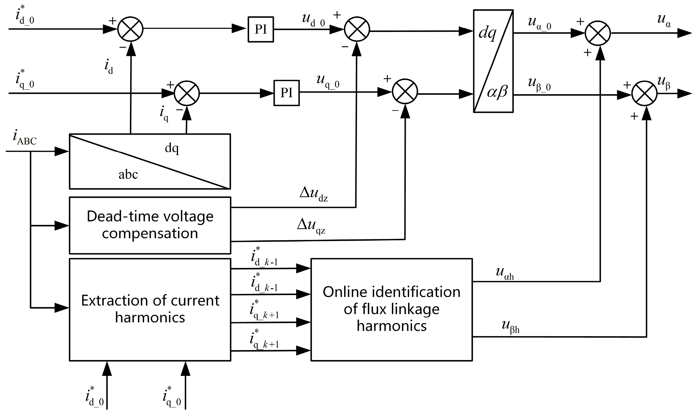
3.1. Current Harmonic Extraction Based on Multiple Synchronous Rotating Reference Frames

To achieve effective control of current harmonics, the accuracy of harmonic extraction is crucial. The method for extracting current harmonics is illustrated in Figure 1.
Based on the dq coordinate transformation, multiple synchronous rotating reference frames are employed to extract the harmonic components. The transformation matrices of the (k − 1)-order and (k + 1)-order synchronous rotating reference frames are given by
Τ dq _ 1 dq _ k 1 = cos k ω e t sin k k ω e t sin k ω e t cos k ω e t
Τ dq _ 1 dq _ k + 1 = cos k ω e t sin k ω e t sin k ω e t cos k ω e t
After applying the transformations in Equations (13) and (14), the dq axis currents can be obtained as follows:
i dh _ k 1 = I d _ k 1 cos ϕ id _ k 1 + I d _ k cos ( ( 2 k 1 ) ω e t + ϕ id _ k 1 ) i qh _ k 1 = I q _ k 1 sin ϕ iq _ k 1 + I q _ k sin ( ( 2 k 1 ) ω e t + ϕ iq _ k 1 )
i dh _ k + 1 = I d _ k + 1 cos ϕ id _ k + 1 + I d k cos ( ( 2 k + 1 ) ω e t + ϕ id _ k + 1 ) i qh _ k + 1 = I q _ k + 1 sin ϕ iq _ k + 1 + I q k sin ( ( 2 k + 1 ) ω e t + ϕ iq _ k + 1 )
From Equations (15) and (16), it can be observed that the (k − 1)-order harmonic component of the PMSM stator current appears as a direct current in the (k − 1)-order synchronous rotating reference frame, while the fundamental and other frequency components appear as alternating currents. Similarly, Equation (16) shows that the (k + 1)-order harmonic component appears as a direct current in the (k + 1)-order synchronous rotating reference frame, whereas the fundamental and other frequency components remain as alternating currents.
Therefore, by filtering out the alternating current components in the stator current within the (k − 1)- and (k + 1)-order synchronous rotating reference frames, the corresponding harmonic components can be extracted as follows:
i d _ k 1 = I d _ k 1 cos ϕ id _ k 1 i q _ k 1 = I q _ k 1 sin ϕ iq _ k 1
i d _ k + 1 = I d _ k + 1 cos ϕ id _ k + 1 i q _ k + 1 = I q _ k + 1 sin ϕ iq _ k + 1

3.2. Dead-Time Compensation Method

The voltage errors Δua, Δub, and Δuc caused by the dead-time can be calculated using the following equation:
Δ u a = 1 3 T d T s [ 2 sgn ( i a ) sgn ( i b ) sgn ( i c ) ] Δ u b = 1 3 T d T s [ 2 sgn ( i b ) sgn ( i a ) sgn ( i c ) ] Δ u c = 1 3 T d T s [ 2 sgn ( i c ) sgn ( i b ) sgn ( i a ) ]
In the equation, the variables ia, ib, and ic represent the three-phase currents obtained from current sensor measurements. The sign function is defined as follows:
sgn ( i a ) = 1 , i a > 0 1 , i a < 0
A coordinate transformation can be applied to Equation (19).
Δ u zd Δ u zq = 2 3 cos ( ω e t ) sin ( ω e t ) cos ( ω e t 2 π 3 ) sin ( ω e t 2 π 3 ) cos ( ω e t + 2 π 3 ) sin ( ω e t + 2 π 3 ) T Δ u a Δ u b Δ u c
Δuzd and Δuzq are injected into the fundamental voltage to eliminate the (k − 1)- and (k + 1)-order voltage harmonics Δuzd_k−1, Δuzq_k−1, Δuzd_k+1, and Δuzq_k+1 caused by the inverter dead time, thereby reducing its impact on the online identification of flux linkage harmonics.

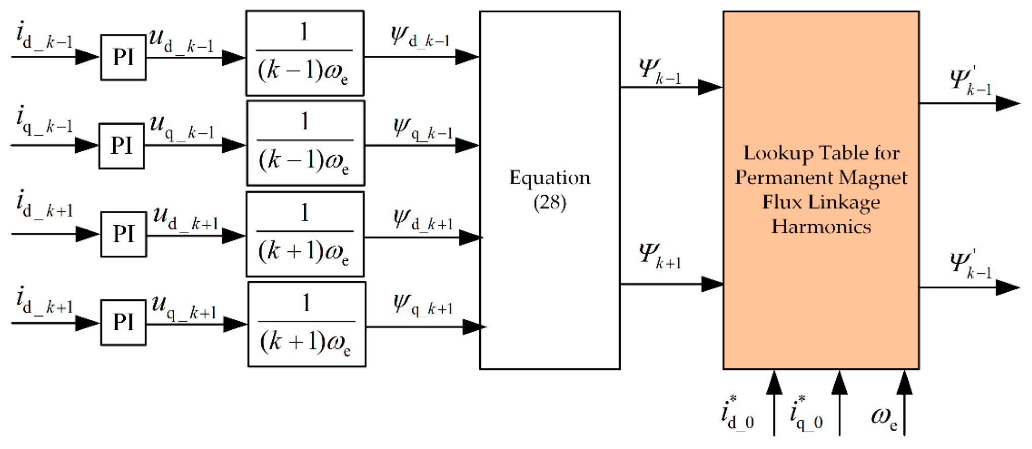
3.3. Online Identification Method for Permanent Magnet Flux Linkage Harmonics

The calculation models for the (k − 1)- and (k + 1)-order d-axis and q-axis current harmonics of the PMSM are described as follows:
Δ u d _ k 1 = R i d _ k 1 + L d d i d _ k 1 d t ω e L q i q _ k 1 + d ψ d _ k 1 d t + k 1 ω e ψ q _ k 1 + Δ u zd _ k 1 Δ u q _ k 1 = R i q _ k 1 + L q d i q _ k 1 d t ω e L d i d _ k 1 + d ψ q _ k 1 d t k 1 ω e ψ d _ k 1 + Δ u zq _ k 1
Δ u d _ k + 1 = R i d _ k + 1 + L d d i d _ k + 1 d t ω e L q i q _ k + 1 + d ψ d _ k + 1 d t k + 1 ω e ψ fq _ k + 1 + Δ u zd _ k + 1 Δ u q _ k + 1 = R i q _ k + 1 + L q d i q _ k + 1 d t ω e L d i d _ k + 1 + d ψ q _ k + 1 d t + k + 1 ω e ψ d _ k + 1 + Δ u zq _ k + 1
The elimination of the (k − 1)- and (k + 1)-order voltage harmonics caused by the inverter dead time using the dead-time compensation algorithm is given by:
Δ u d _ k 1 = R i d _ k 1 + L d d i d _ k 1 d t ω e L q i q _ k 1 + d ψ d _ k 1 d t + k 1 ω e ψ q _ k 1 Δ u q _ k 1 = R i q _ k 1 + L q d i q _ k 1 d t ω e L d i d _ k 1 + d ψ q _ k 1 d t k 1 ω e ψ d _ k 1
Δ u d _ k + 1 = R i d _ k + 1 + L d d i d _ k + 1 d t ω e L q i q _ k + 1 + d ψ d _ k + 1 d t k + 1 ω e ψ q _ k + 1 Δ u q _ k + 1 = R i q _ k + 1 + L q d i q _ k + 1 d t ω e L d i d _ k + 1 + d ψ q _ k + 1 d t + k + 1 ω e ψ d _ k + 1
To reduce the impact of motor parameter variations and enhance the robustness of the algorithm, the (k − 1)- and (k + 1)-order current harmonics (id_k−1, iq_k−1, id_k+1, iq_k+1) are regulated to zero using a harmonic current controller. Under this condition, the output harmonic voltage command from the controller corresponds to the voltage generated by the harmonic components of the permanent magnet flux linkage. Since the differential term is negligible, it can be ignored. The identified values of the (k − 1)- and (k + 1)-order flux linkage harmonics are given by:
ψ d _ k 1 = Δ u q _ k 1 k 1 ω e ψ q _ k 1 = Δ u d _ k 1 k 1 ω e
ψ d _ k + 1 = Δ u q _ k + 1 k + 1 ω e ψ q _ k + 1 = Δ u d _ k + 1 k + 1 ω e
Ψ k 1 = ψ d _ k 1 2 + ψ q _ k 1 2 Ψ k + 1 = ψ d _ k + 1 2 + ψ q _ k + 1 2
To enable the fast acquisition of high-order harmonics in the permanent magnet flux linkage during motor operation, this paper introduces a harmonic parameter identification strategy based on a lookup table approach. In Figure 2, Ψk−1 and Ψk+1 represent the estimated values of the (k − 1)- and (k + 1)-order flux linkage harmonics, respectively, and serve as key input parameters for the subsequent calculation of current harmonic reference values.
To meet the real-time performance requirements for Ψk−1 and Ψk+1, an offline table-building method is employed to construct a three-dimensional lookup table in advance. During the table construction process, the reference values of dq axis currents (id0*, iq0*) and the electrical angular velocity ωe are used as input variables. These parameters are discretized over the expected operating range, and the corresponding values of Ψk−1 and Ψk+1 at each discrete operating point are obtained using a flux harmonic identification method.
Finally, all discrete harmonic data are processed through three-dimensional interpolation to generate a complete lookup table, which is embedded in the control system for real-time use.
As shown in Figure 3, this method outlines the online identification process of flux linkage harmonics based on multiple synchronous rotating coordinate systems. First, a dead-time compensation algorithm is applied to correct the voltage error caused by inverter dead-time effects. Then, using the multi-synchronous rotating coordinate system theory based on current reconstruction, the current harmonics induced by the permanent magnet flux linkage harmonics are extracted. On this basis, the flux linkage harmonics of the permanent magnets are calculated by combining the harmonic voltage information from the controller output. Finally, the calculated harmonic voltage compensation values are injected into the uα_0 and uβ_0 components, thereby achieving online identification of the flux linkage harmonics.

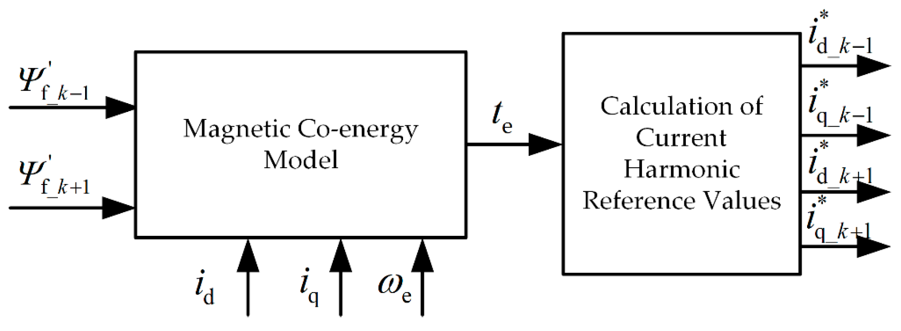
4. Torque Ripple Suppression Strategies

To mitigate torque fluctuations induced by harmonics in the permanent magnet flux linkage, a harmonic current must be superimposed on the original stator current. To obtain this harmonic current, torque ripple is first predicted using the magnetic co-energy model based on the identified flux linkage harmonics. Then, the reference values of the harmonic current are calculated analytically. The overall process is illustrated in Figure 4.
To ensure that the torque ripple caused by harmonics is minimized, the following condition must be satisfied:
min max ( t k ) min ( t k )
The expression for the k-th-order torque ripple is given by
t k = 3 p 2 L d L q I d _ 0 + ψ d _ 0 I q _ k sin k ω e t ϕ iq _ k   + 3 p 2 L d L q I q _ 0 I d _ k cos k ω e t ϕ id _ k   + 3 p 2 I q _ 0 ψ d _ k + k ψ q _ k cos k ω e t   3 p 2 I d _ 0 k ψ d _ k + ψ q _ k sin k ω e t
It can be observed from the expression that as the load torque increases, the fundamental current components id and iq also increase accordingly. This intensifies the coupling between the fundamental current and the harmonic components of the flux linkage, resulting in more pronounced torque ripple. Therefore, suppressing torque ripple becomes particularly important under high-load operating conditions.
The primary objective of the stator current harmonics used for torque ripple suppression is to
t k = 0
However, the stator harmonic currents used to minimize torque ripple introduce additional power losses in the motor, which are approximately proportional to the square of the harmonic current amplitude. Therefore, the second objective in the stator current optimization design is to minimize the motor losses caused by harmonic currents, that is, to minimize the squared amplitude of the harmonic currents,
min ( I d _ k 2 + I q _ k 2 )
According to the analytical solution presented in [16], the harmonic current used for torque ripple suppression is given by
i d _ k * = I d _ k * cos ( k ω e t + ϕ d _ k * ) i q _ k * = I q _ k * sin ( k ω e t + ϕ q _ k * )
The amplitude of the harmonic current is expressed as
I d _ k * = L Δ I q 0 E k 2 + F k 2 L Δ I d 0 + Ψ 0 2 + L Δ I q 0 2 I q _ k * = L Δ I d 0 + Ψ 0 E k 2 + F k 2 L Δ I d 0 + Ψ 0 2 + L Δ I q 0 2
E k = K P I q 0 ψ d _ k + k ψ q _ k F k = K P I d 0 k ψ d _ k + ψ q _ k
As the squared sum of harmonic current amplitudes is roughly proportional to the associated motor losses, the stator harmonic currents must adopt optimal phase angles that satisfy the following condition:
ϕ id _ k * = arctan F k E 12 + π ϕ iq _ k * = arctan F k E k + π 2
Accordingly, the reference values of the (k − 1)- and (k + 1)-order current harmonics in the synchronous rotating reference frame are calculated as
i d _ k 1 * = 1 2 I d _ k * cos ϕ id _ k * I q _ k * cos ϕ iq _ k * i q _ k 1 * = 1 2 I d _ k * sin ϕ id _ k * I q _ k * sin ϕ iq _ k *
i d _ k + 1 * = 1 2 I d _ k * cos μ id _ k * + I q _ k * cos μ iq _ k * i q _ k + 1 * = 1 2 I d _ k * sin μ id _ k * + I q _ k * sin μ iq _ k *

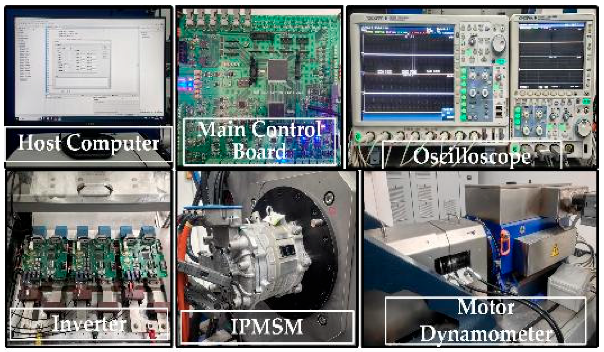
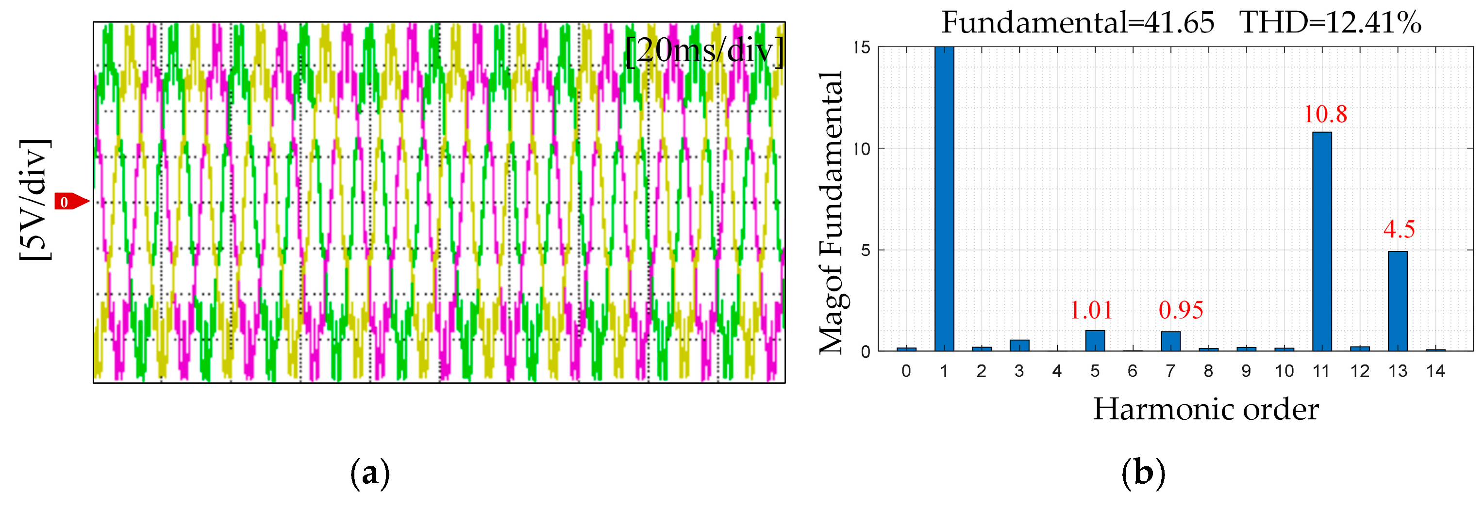
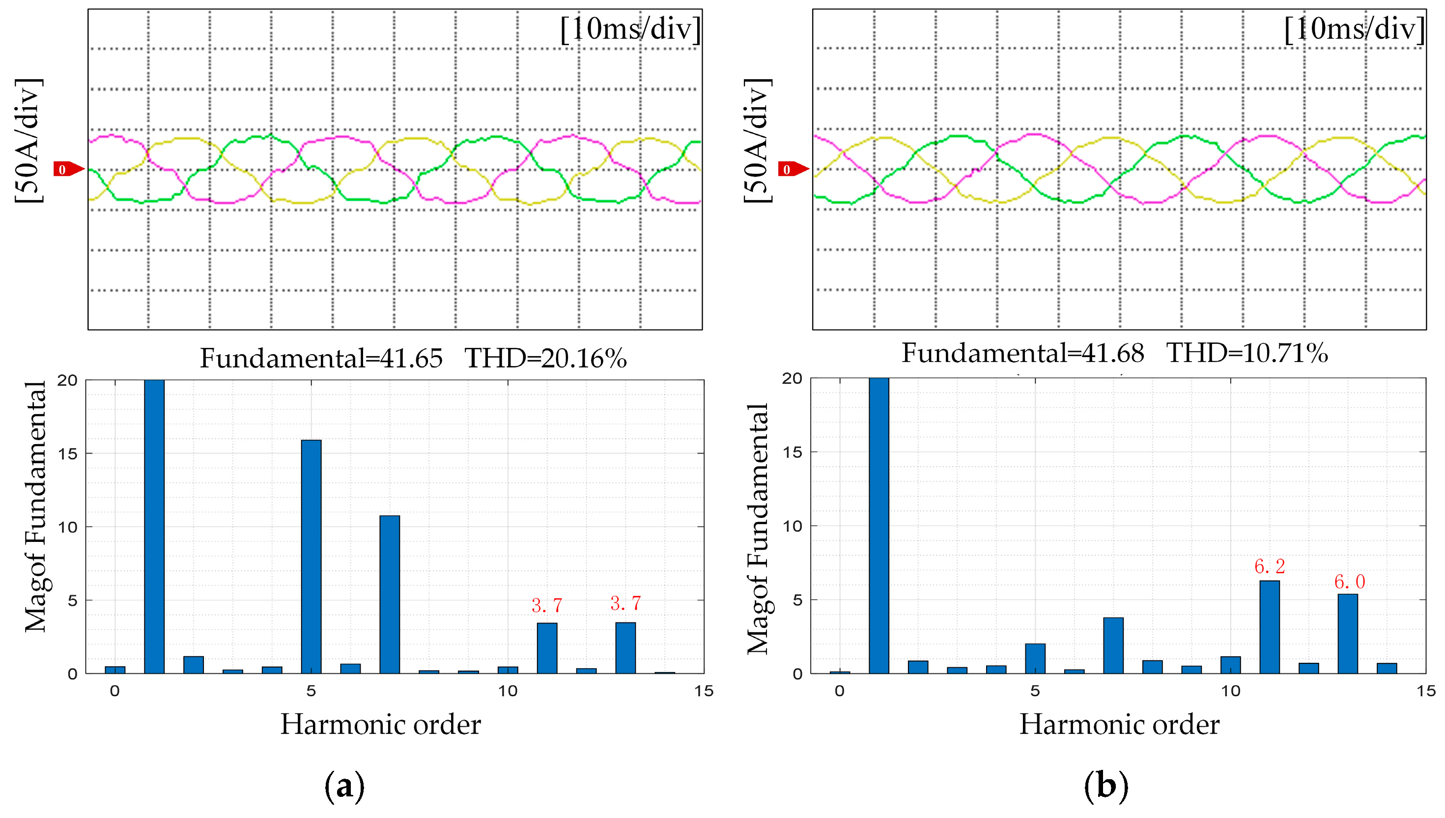
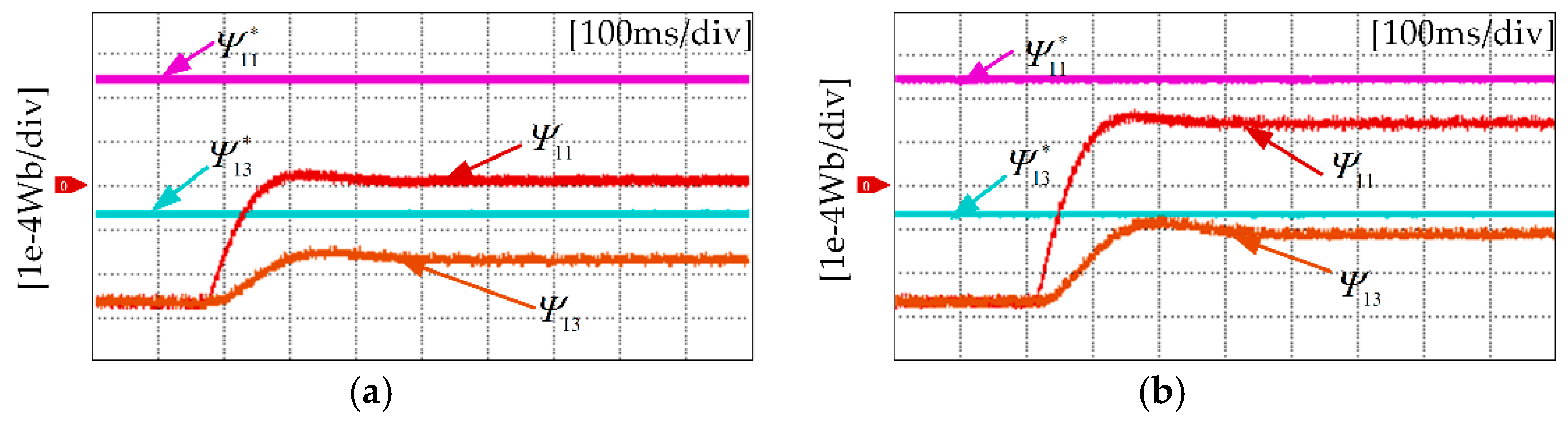
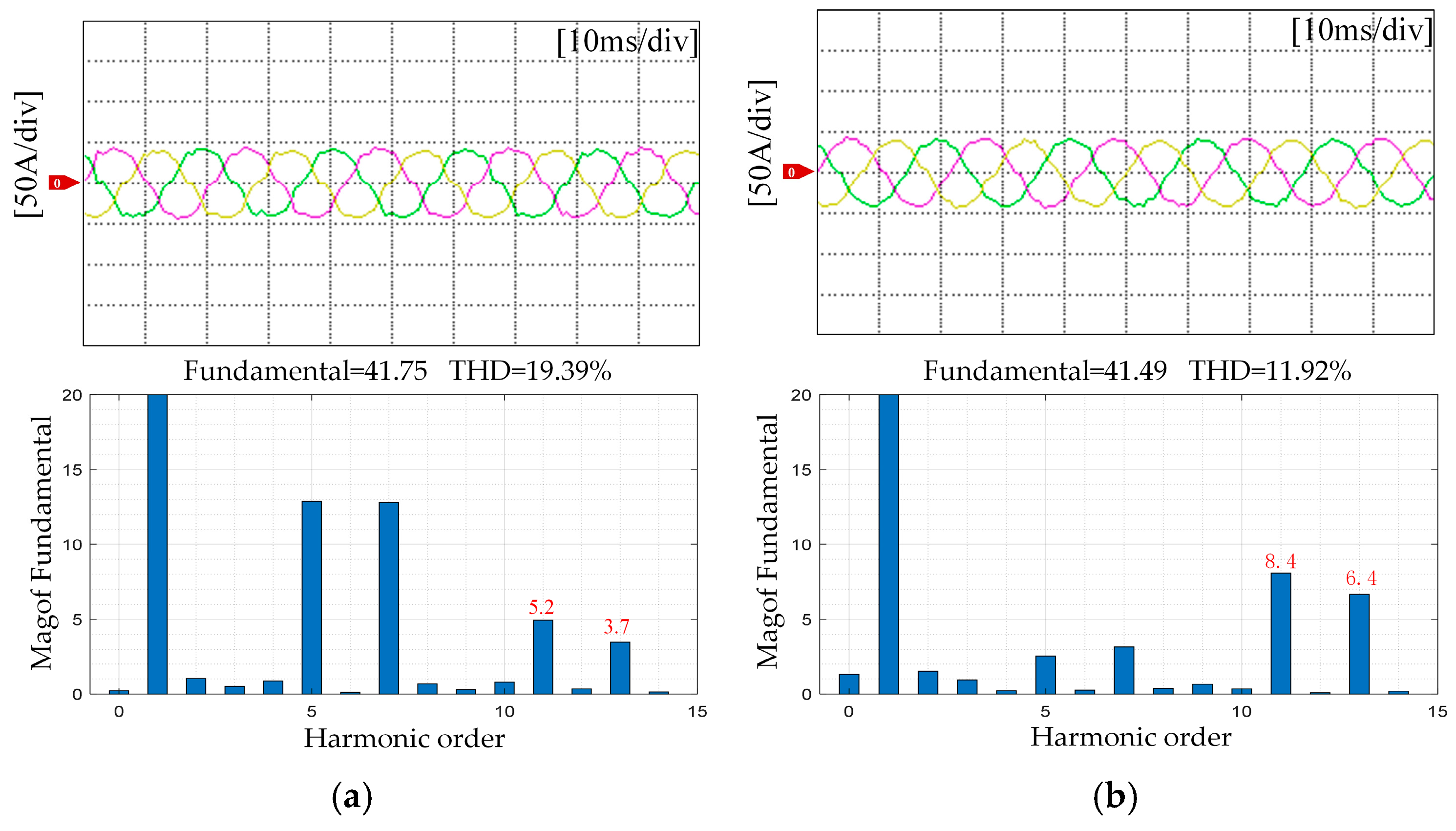
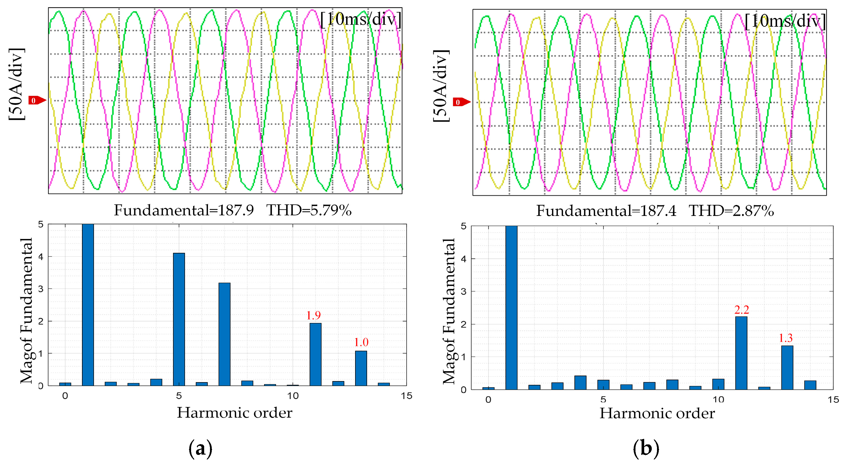
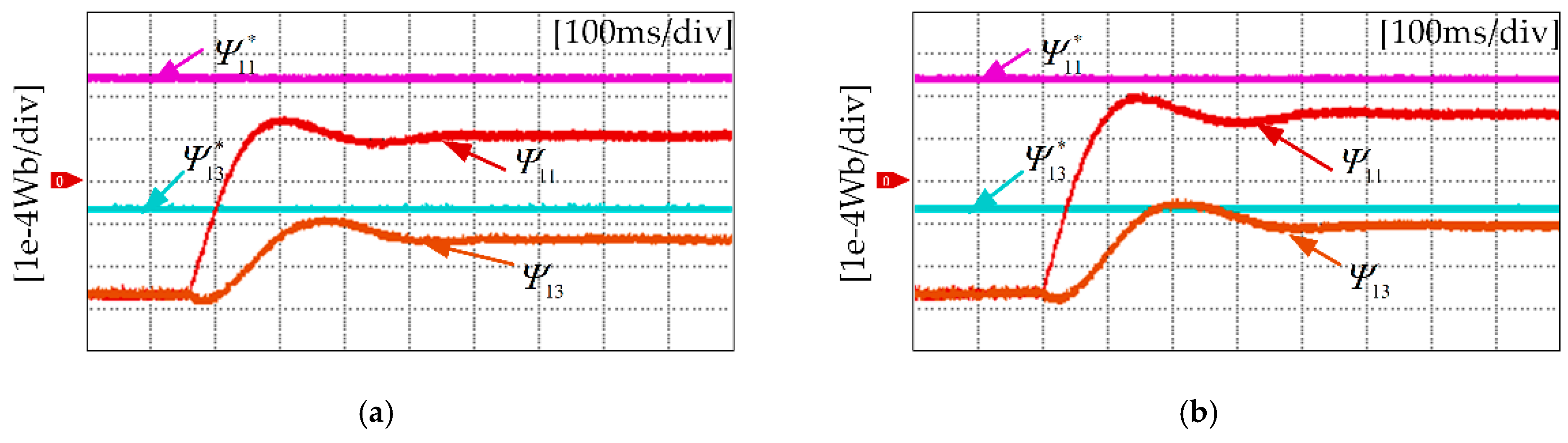
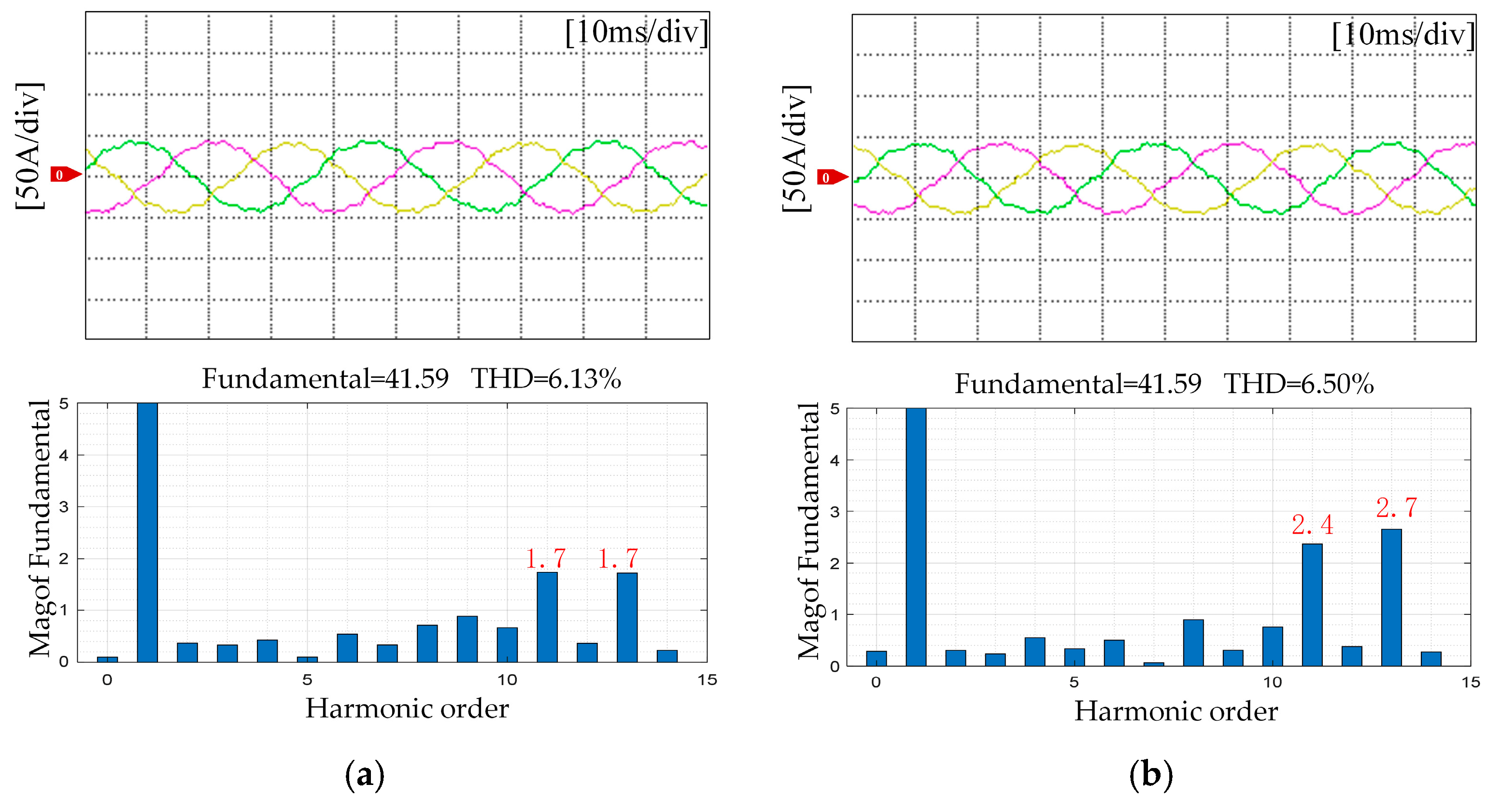
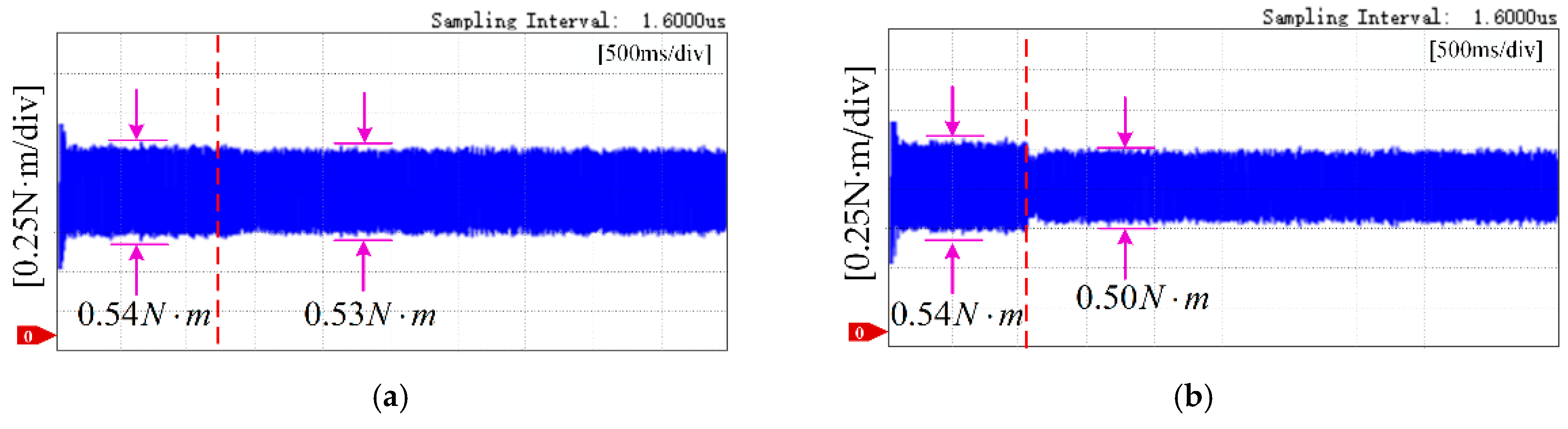
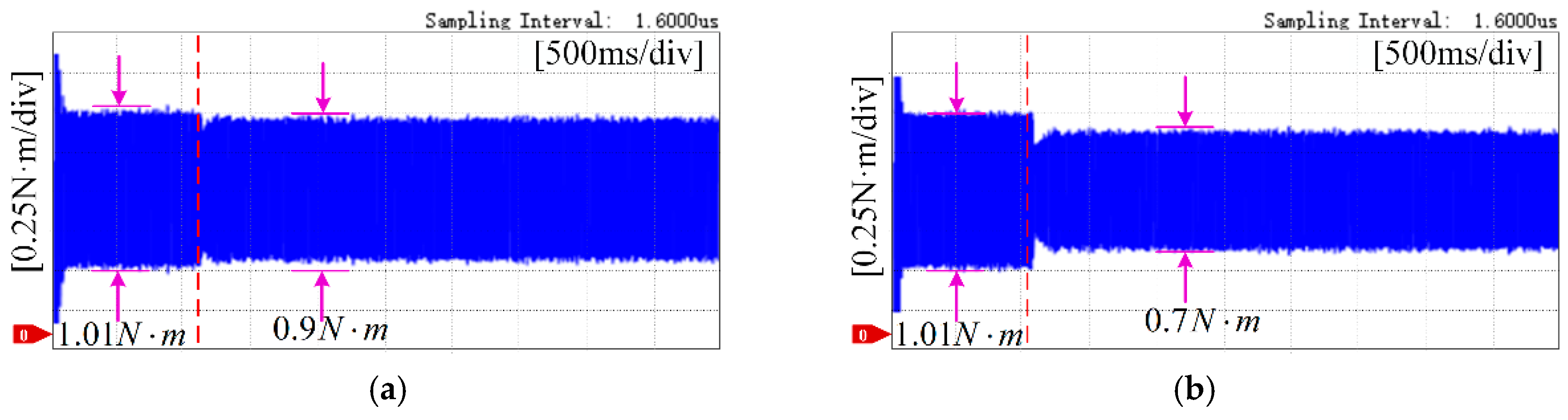
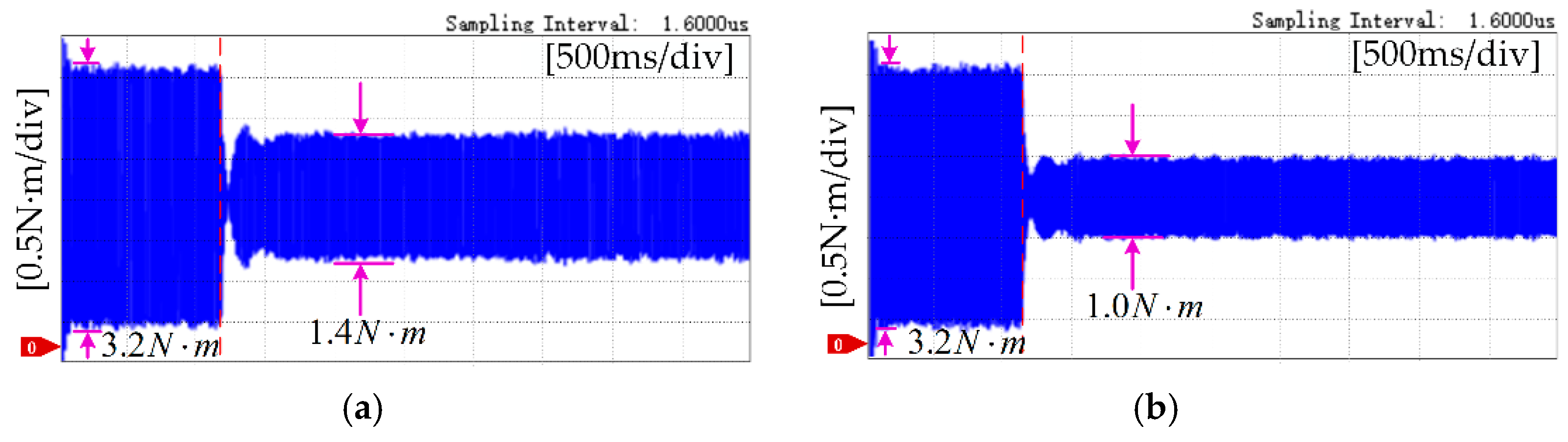
5. Experimental Results

To demonstrate the validity of the proposed approach, an experimental motor control platform was established, as illustrated in Figure 5. During testing, torque output was recorded using an HBM T12HP torque sensor. Key specifications of the prototype PMSM are provided in Table 1.

5.1. Flux Linkage Harmonic Identification

To enable the comparison of flux linkage identification results, it is first necessary to acquire the actual flux linkage values of the prototype motor. In this paper, the tested motor is rotated by a dynamometer, and the flux linkage information is extracted by collecting its back-EMF waveform. Under steady-state conditions at a speed of 600 r/min, the recorded back-EMF waveform is shown in Figure 6a, and its frequency spectrum obtained through Fourier transform analysis is shown in Figure 6b.
It should be pointed out that the permanent magnet flux linkage is determined by the internal structure of the motor, and its harmonic components remain unchanged at different speeds, exhibiting a speed-independent characteristic. According to Equations (11) and (12), the amplitudes of each order harmonic of the permanent magnet flux linkage can be accurately calculated, and the obtained values are shown in Table 2.
As can be seen from the table, the 11th- and 13th-order high-order harmonic components in the permanent magnet flux linkage of the prototype are relatively significant. The following experiments in this paper will focus on the verification and analysis of these two harmonic components.
In the harmonic current controller, the PI parameters were set as Kp = 0.5 and Ki = 10, based on conventional tuning principles to balance response speed and steady-state accuracy. These values were verified through simulation to ensure control stability and effective harmonic suppression.
Figure 7 illustrates the variation in three-phase current waveforms at 400 r/min and 10 N·m, before and after applying the dead-time compensation algorithm. In Figure 7’s three-phase current waveforms, the yellow line represents phase A current, the green line represents phase B current, and the red line represents phase C current. The color coding for the current waveform lines in subsequent figures follows this same convention. As shown, the implementation of the algorithm reduces the Total Harmonic Distortion (THD) from 21.01% to 11.74%, reflecting a marked enhancement in current waveform quality. However, the amplitudes of the 11th- and 13th-order current harmonics do not decrease; instead, they increase. This is mainly because, without the dead-time compensation, the 11th and 13th current harmonics caused by the dead-time effect partially cancel out the flux linkage harmonics at the same frequencies, thereby reducing the harmonic content in this frequency band to some extent.
With the implementation of dead-time compensation, the cancellation effect diminishes, leading to a rise in the 11th and 13th harmonic amplitudes.
Figure 8 shows the identification results of permanent magnet flux linkage harmonics under the operating condition of 400 r/min and 10 N·m load torque. As shown in Figure 8a, without considering the inverter dead time, the traditional flux linkage harmonic identification method yields Ψ11 = 2.11 × 10⁻⁴ Wb and Ψ13 = 0.74 × 10⁻⁴ Wb. Compared with the measured values listed in Table 2, the absolute errors are 45% and 51%, respectively.
When the dead-time compensation is introduced, the proposed method gives Ψ11 = 3.09 × 10⁻⁴ Wb and Ψ13 = 1.17 × 10⁻⁴ Wb, as shown in Figure 8b, with the corresponding absolute errors reduced to 20% and 23%. These results indicate that the inverter dead time introduces a systematic deviation in flux linkage harmonic identification, which can be effectively mitigated by targeted compensation, thereby improving the estimation accuracy.
Figure 9 displays the three-phase current waveforms recorded at 700 r/min and 10 N·m. With the application of the dead-time compensation algorithm, the Total Harmonic Distortion (THD) drops from 19.87% to 13.22%.
It is worth noting that, compared with the case at 400 r/min, the amplitudes of the 11th and 13th current harmonics increase. This phenomenon is caused by the increase in current harmonics induced by the permanent magnet flux linkage harmonics as the speed increases. Before compensation, there exists a certain cancellation effect between the dead-time effect and the flux linkage harmonics in this frequency range, which results in relatively smaller amplitudes of the 11th and 13th harmonics. After compensation, this cancellation effect is eliminated, leading to an increase in harmonic amplitudes in this frequency band.
The identification results of permanent magnet flux linkage harmonics at 700 r/min and 10 N·m are illustrated in Figure 10. As shown in Figure 10a, without considering the inverter dead time, the traditional flux linkage harmonic identification method yields Ψ11 = 2.33 × 10⁻⁴ Wb and Ψ13 = 0.79 × 10⁻⁴ Wb, with absolute errors of 39% and 48%, respectively. When the dead-time compensation is introduced, the proposed method provides identification results of Ψ11 = 3.28 × 10⁻⁴ Wb and Ψ13 = 1.25 × 10⁻⁴ Wb, as shown in Figure 10b, with the corresponding absolute errors reduced to 20% and 23%.
As the speed increases, the current harmonics caused by the flux linkage harmonics become larger, which helps improve the accuracy of their identification.
Figure 11 illustrates the three-phase current waveforms at 700 r/min and 60 N·m. With the application of dead-time compensation, the THD drops from 6.70% to 4.58%. However, after compensation, the amplitudes of the 11th and 13th harmonic currents exhibit an increase.
Figure 12 shows the identification results of permanent magnet flux linkage harmonics under the operating conditions of 700 r/min and 60 N·m load torque. As shown in Figure 12a, without considering the inverter dead time, the traditional flux linkage harmonic identification method yields Ψ11 = 2.82 × 10⁻⁴ Wb and Ψ13 = 0.95 × 10⁻⁴ Wb, with absolute errors of 25% and 37%, respectively. When the dead-time compensation is introduced, as shown in Figure 12b, the outcomes of the proposed identification technique are Ψ11 = 3.19 × 10⁻⁴ Wb and Ψ13 = 1.20 × 10⁻⁴ Wb, and the corresponding absolute errors are reduced to 17% and 21%.
Figure 13 shows the comparison of flux linkage identification errors under different speeds and load torques. It can be clearly seen from the figure that, compared with the traditional method, the proposed method exhibits higher identification accuracy under various speed and load conditions, with the advantage being more pronounced under high-speed and high-load scenarios, thus verifying its good adaptability and accuracy.

5.2. Torque Ripple Suppression

Based on the identified flux linkage harmonics, a torque ripple suppression experiment was carried out.
Figure 14 presents the three-phase current waveforms and their corresponding Fourier spectra at 400 r/min and 10 N·m torque after harmonic current injection. Compared to the conventional method, the THD is noticeably higher. This increase is attributed to the improved accuracy in flux linkage harmonic identification achieved by the proposed method, leading to more pronounced 11th- and 13th-order current harmonics.
As shown in Figure 15, under the operating conditions of 400 rpm and 10 N·m torque, it is difficult to directly observe the 12th-order torque ripple due to the presence of multiple frequency components in the torque waveform collected by the torque sensor. Therefore, a band-pass filter with a cutoff frequency of 320 Hz ± 50 Hz is applied to process the torque waveform.
After filtering, it can be seen that in the traditional torque ripple suppression method, the peak-to-peak value of the torque ripple is reduced from 0.54 N·m to 0.53 N·m after injecting the current harmonics, showing little improvement. In contrast, the proposed method reduces the peak-to-peak value from 0.54 N·m to 0.50 N·m, demonstrating relatively better suppression performance.
Figure 16 illustrates that at 700 r/min and 10 N·m, both the traditional and proposed identification methods yield more accurate results compared to lower-speed conditions. As a result, the magnitude of the injected current harmonics is greater than that at 400 r/min and 10 N·m.
Figure 17 shows the torque waveform sampled at 700 r/min and 10 N·m, as well as the result after processing with a band-pass filter with a cutoff frequency of 560 Hz ± 50 Hz.
Compared with the 400 r/min condition, the peak-to-peak value of the torque ripple increases from 0.54 N·m to 1.01 N·m, which is caused by the intensified current harmonics due to the increased speed. The traditional method reduces it to 0.9 N·m, while the proposed method further reduces it to 0.7 N·m, demonstrating better suppression performance.
Although the torque ripple suppression effect of the proposed method is also not significant, this is mainly because the flux linkage harmonics of the motor are relatively small, and the fundamental current is low under low-load conditions, resulting in inherently small torque ripple caused by the flux linkage harmonics. However, it can be observed that, compared with the traditional method, the proposed method still shows a more obvious advantage in torque ripple suppression.
As shown in Figure 18, under the operating conditions of 700 rpm and 60 N·m torque, the three-phase current waveforms and their FFT spectrum analysis results are presented. Figure 17 shows the torque waveforms obtained by the traditional method and the proposed method after filtering.
As shown in Figure 19, the filtered results under the conditions of 700 r/min and 60 N·m torque indicate that the torque ripple increases significantly compared with the low-load condition. This is because, as the load torque increases, the fundamental current of the motor also increases accordingly, which enhances the coupling effect between the fundamental current and the flux linkage harmonics, leading to an increase in the amplitude of the torque ripple.
Under this operating condition, the traditional torque ripple suppression method reduces the peak-to-peak value of the torque ripple from 3.2 N·m to 1.4 N·m by injecting current harmonics, achieving a 56.25% reduction. In contrast, the proposed method further reduces the torque ripple to 1.0 N·m, corresponding to a 68.75% reduction. It is evident that the proposed method demonstrates better performance in torque ripple suppression compared with the traditional method.
In summary, the comparison between the traditional torque ripple suppression method and the proposed method under different operating conditions shows that, under low-speed and light-load conditions (400 r/min, 10 N·m), due to the relatively small permanent magnet flux linkage harmonics and fundamental current, the amplitude of the torque ripple is limited. Therefore, the improvement in torque ripple suppression is not significant for either method, but the proposed method still demonstrates better performance.
Under high-speed and heavy-load conditions (700 r/min, 60 N·m), as the fundamental and harmonic currents increase, the torque ripple becomes more pronounced, making suppression more important. Under this condition, the proposed method effectively reduces the torque ripple amplitude from 3.2 N·m to 1.0 N·m, achieving better suppression performance than the traditional method, which verifies its potential and advantage under high-speed and high-load operating conditions.

6. Discussion

This paper proposes an improved online identification method for flux linkage harmonics and applies it to torque ripple suppression control. The proposed method introduces a dead-time compensation algorithm, which effectively compensates for the current harmonics caused by inverter dead time, thereby improving the accuracy of flux linkage harmonic identification.
On this basis, the torque ripple suppression strategy is further improved. Experimental results show that, compared with the traditional torque ripple suppression method, the proposed method exhibits a clear advantage in suppression performance, especially under high-speed and high-load operating conditions.

Author Contributions

Conceptualization, Z.W. and X.G.; methodology, Z.W. and B.Z.; software, B.Z.; validation, B.Z. and X.J.; formal analysis, B.Z. and X.G.; writing—original draft preparation, B.Z.; writing—review and editing, X.G., G.Z. and Z.L.; funding acquisition, Z.W. and X.G. All authors have read and agreed to the published version of the manuscript.

Funding

This research was funded by Zhejiang Provincial Natural Science Foundation of China, grant number LD24E070001” and the “National Natural Science Foundation of China, grant number 52177055”.

Data Availability Statement

Data are contained within the article.

Conflicts of Interest

The authors declare no conflicts of interest.

References

  1. Lan, Y.; Benomar, Y.; Deepak, K.; Aksoz, A.; Baghdadi, M.E.; Bostanci, E.; Hegazy, O. Switched Reluctance Motors and Drive Systems for Electric Vehicle Powertrains: State of the Art Analysis and Future Trends. Energies 2021, 14, 2079. [Google Scholar] [CrossRef]
  2. Lv, C.; Wang, B.; Chen, J.; Zhang, R.; Dong, H.; Wan, S. Research on a Torque Ripple Suppression Method of Fuzzy Active Disturbance Rejection Control for a Permanent Magnet Synchronous Motor. Electronics 2024, 13, 1280. [Google Scholar] [CrossRef]
  3. Li, H.; Guo, Y.; Xu, Q. PMSM Torque Ripple Suppression Method Based on SMA-Optimized ILC. Sensors 2023, 23, 9317. [Google Scholar] [CrossRef] [PubMed]
  4. Han, J.; Su, H.; Li, W.; Yuan, H. A VSFPWM Strategy for High Frequency Torque Ripple Control of PMSM Based on Stator Flux Ripple Prediction. Trans. Electr. Mach. Syst. 2024, 8, 414–425. [Google Scholar] [CrossRef]
  5. Qu, J.; Gao, F.; Zhang, P.; Dong, Y. Motor-Parameter-Free Solution of Optimal Harmonic Currents for Torque Ripple Reduction of PMSM Drives with Response Surface Method. IEEE J. Emerg. Sel. Top. Power Electron. 2024, 12, 2774–2786. [Google Scholar] [CrossRef]
  6. Mohan, A.; Khalid, M.; Binojkumar, A.C. A Novel Sliding Hysteresis Band Based Direct Torque Control Scheme for PMSM Motors to Achieve Improved Current THD With Reduction in Torque and Flux Ripples Eliminating the Low-Speed Problems. IEEE Access 2024, 12, 67971–67985. [Google Scholar] [CrossRef]
  7. Chuan, H.; Fazeli, S.M.; Wu, Z.; Burke, R. Mitigating the Torque Ripple in Electric Traction Using Proportional Integral Resonant Controller. IEEE Trans. Veh. Technol. 2020, 69, 10820–10831. [Google Scholar] [CrossRef]
  8. Kang, G.-H.; Son, Y.-D.; Kim, G.-T.; Hur, J. A Novel Cogging Torque Reduction Method for Interior-Type Permanent-Magnet Motor. IEEE Trans. Ind. Appl. 2009, 45, 161–167. [Google Scholar] [CrossRef]
  9. Zhu, Z.Q.; Liu, Y. Analysis of Air-Gap Field Modulation and Magnetic Gearing Effect in Fractional-Slot Concentrated-Winding Permanent-Magnet Synchronous Machines. IEEE Trans. Ind. Electron. 2018, 65, 3688–3698. [Google Scholar] [CrossRef]
  10. Gulez, K.; Adam, A.A.; Pastaci, H. Torque Ripple and EMI Noise Minimization in PMSM Using Active Filter Topology and Field-Oriented Control. IEEE Trans. Ind. Electron. 2008, 55, 251–257. [Google Scholar] [CrossRef]
  11. Lai, C.; Feng, G.; Iyer, K.L.V.; Mukherjee, K.; Kar, N.C. Genetic Algorithm-Based Current Optimization for Torque Ripple Reduction of Interior PMSMs. IEEE Trans. Ind. Appl. 2017, 53, 4493–4503. [Google Scholar] [CrossRef]
  12. Rafaq, M.S.; Midgley, W.; Steffen, T. A Review of the State of the Art of Torque Ripple Minimization Techniques for Permanent Magnet Synchronous Motors. IEEE Trans. Ind. Inf. 2024, 20, 1019–1031. [Google Scholar] [CrossRef]
  13. Flieller, D.; Nguyen, N.K.; Wira, P.; Sturtzer, G.; Abdeslam, D.O.; Merckle, J. A Self-Learning Solution for Torque Ripple Reduction for Nonsinusoidal Permanent-Magnet Motor Drives Based on Artificial Neural Networks. IEEE Trans. Ind. Electron. 2014, 61, 655–666. [Google Scholar] [CrossRef]
  14. Zhang, X.; Li, Z. Sliding-Mode Observer-Based Mechanical Parameter Estimation for Permanent Magnet Synchronous Motor. IEEE Trans. Power Electron. 2016, 31, 5732–5745. [Google Scholar] [CrossRef]
  15. Qian, W.; Panda, S.K.; Xu, J.-X. Torque Ripple Minimization in PM Synchronous Motors Using Iterative Learning Control. IEEE Trans. Power Electron. 2004, 19, 272–279. [Google Scholar] [CrossRef]
  16. Feng, G.; Lai, C.; Kar, N.C. An Analytical Solution to Optimal Stator Current Design for PMSM Torque Ripple Minimization with Minimal Machine Losses. IEEE Trans. Ind. Electron. 2017, 64, 7655–7665. [Google Scholar] [CrossRef]
  17. Liu, Z.-H.; Wei, H.-L.; Li, X.-H.; Liu, K.; Zhong, Q.-C. Global Identification of Electrical and Mechanical Parameters in PMSM Drive Based on Dynamic Self-Learning PSO. IEEE Trans. Power Electron. 2018, 33, 10858–10871. [Google Scholar] [CrossRef]
  18. Inoue, Y.; Kawaguchi, Y.; Morimoto, S.; Sanada, M. Performance Improvement of Sensorless IPMSM Drives in a Low-Speed Region Using Online Parameter Identification. IEEE Trans. Ind. Appl. 2011, 47, 798–804. [Google Scholar] [CrossRef]
  19. Liu, K.; Zhu, Z.Q. Mechanical Parameter Estimation of Permanent-Magnet Synchronous Machines with Aiding from Estimation of Rotor PM Flux Linkage. IEEE Trans. Ind. Appl. 2015, 51, 3115–3125. [Google Scholar] [CrossRef]
  20. Bedetti, N.; Calligaro, S.; Petrella, R. Stand-Still Self-Identification of Flux Characteristics for Synchronous Reluctance Machines Using Novel Saturation Approximating Function and Multiple Linear Regression. IEEE Trans. Ind. Appl. 2016, 52, 3083–3092. [Google Scholar] [CrossRef]
  21. Kim, H.; Han, Y.; Lee, K.; Bhattacharya, S. A Sinusoidal Current Control Strategy Based on Harmonic Voltage Injection for Harmonic Loss Reduction of PMSMs With Non-Sinusoidal Back-EMF. IEEE Trans. Ind. Appl. 2020, 56, 7032–7043. [Google Scholar] [CrossRef]
  22. Chen, Z.; Shi, T.; Lin, Z.; Wang, Z.; Gu, X. Analysis and Control of Current Harmonic in IPMSM Field-Oriented Control System. IEEE Trans. Power Electron. 2022, 37, 9571–9585. [Google Scholar] [CrossRef]
Figure 1. Method for extracting current harmonics.
Electronics 14 02174 g001
Figure 2. Flux linkage harmonic identification method.
Electronics 14 02174 g002
Figure 3. Online identification method for flux linkage harmonics based on multi-synchronous reference rrames.
Electronics 14 02174 g003
Figure 4. Torque ripple suppression strategy based on flux linkage identification.
Electronics 14 02174 g004
Figure 5. Experimental system.
Electronics 14 02174 g005
Figure 6. Line voltage waveform and Fourier analysis obtained by the offline method. (a) Line voltage. (b) Fourier analysis.
Electronics 14 02174 g006
Figure 7. Three-phase current waveforms and Fourier analysis before and after dead-time compensation (400 r/min, 10 N·m). (a) Before compensation. (b) After compensation.
Electronics 14 02174 g007
Figure 8. Identification results of permanent magnet flux linkage harmonics (400 r/min, 10 N·m). (a) Traditional method. (b) Proposed method.
Electronics 14 02174 g008
Figure 9. Three-phase current waveforms and Fourier analysis before and after dead-time compensation (700 r/min, 10 N·m). (a) Before compensation. (b) After compensation.
Electronics 14 02174 g009
Figure 10. Identification results of permanent magnet flux linkage harmonics (700 r/min, 10 N·m). (a) Traditional method. (b) Proposed method.
Electronics 14 02174 g010
Figure 11. Three-phase current waveforms and Fourier analysis before and after dead-time compensation (700 r/min, 60 N·m). (a) Before compensation. (b) After compensation.
Electronics 14 02174 g011
Figure 12. Identification results of permanent magnet flux linkage harmonics (700 r/min, 60 N·m). (a) Traditional method. (b) Proposed method.
Electronics 14 02174 g012
Figure 13. Comparison of flux linkage harmonic identification results under different speeds and loads. (a) Identification error of the 11th-order flux linkage harmonic. (b) Identification error of the 13th-order flux linkage harmonic.
Electronics 14 02174 g013
Figure 14. Three-phase current waveforms and FFT analysis after injecting current harmonics (400 r/min, 10 N·m). (a) Traditional method. (b) Proposed method.
Electronics 14 02174 g014
Figure 15. Torque waveform after injecting current harmonics (400 r/min, 10 N·m). (a) Traditional method. (b) Proposed method.
Electronics 14 02174 g015
Figure 16. Three-phase current waveforms and FFT analysis after injecting current harmonics (700 r/min, 10 N·m). (a) Traditional method. (b) Proposed method.
Electronics 14 02174 g016
Figure 17. Torque waveform after injecting current harmonics (700 r/min, 10 N·m). (a) Traditional method. (b) Proposed method.
Electronics 14 02174 g017
Figure 18. Three-phase current waveforms and FFT analysis after injecting current harmonics (700 r/min, 60 N·m). (a) Traditional method. (b) Proposed method.
Electronics 14 02174 g018
Figure 19. Torque waveform after injecting current harmonics (700 r/min, 60 N·m). (a) Traditional method. (b) Proposed method.
Electronics 14 02174 g019
Table 1. Parameters of the permanent magnet synchronous motor used in the experiment.
Motor ParameterSymbolUnitValue
Rated voltage UNV346
Rated currentiNA180
Number of pole pairsp--4
Stator resistanceRΩ0.03
d-axis inductanceLdH0.1049
q-axis inductanceLqH0.3453
Flux linkageΨ0Wb0.038749
Table 2. True values of flux linkage harmonics.
Ψ5* (Wb)Ψ7* (Wb)Ψ11* (Wb)Ψ13* (Wb)
9.54 × 10−55.1054 × 10−53.8454 × 10−41.5254 × 10−4
Disclaimer/Publisher’s Note: The statements, opinions and data contained in all publications are solely those of the individual author(s) and contributor(s) and not of MDPI and/or the editor(s). MDPI and/or the editor(s) disclaim responsibility for any injury to people or property resulting from any ideas, methods, instructions or products referred to in the content.

