Article

Characteristics Improvement of Brushless Doubly-Fed Wind Turbine Generator with Minimized Asymmetric Phenomena

1
College of Automation & College of Artificial Intelligence, Nanjing University of Posts and Telecommunications, Nanjing 210023, China
2
Weifu High-Technology Group Co., Ltd., Wuxi 214028, China
*
Author to whom correspondence should be addressed.
These authors contributed equally to this work.
Electronics 2025, 14(8), 1649; https://doi.org/10.3390/electronics14081649
Submission received: 5 March 2025 / Revised: 6 April 2025 / Accepted: 15 April 2025 / Published: 19 April 2025

Abstract

:
Compared with the traditional brushless doubly-fed generator (BDFG), the BDFG with double stator (BDFG-DS) architecture achieves enhanced configurability by physically decoupling the power and control windings onto independent stator assemblies. The design offers benefits such as expanded slot dimensions and enhanced power density, yet it remains constrained by inherent asymmetry in three phases, which causes large harmonics and torque ripples. In this paper, the working mechanism of the BDFG-DS is introduced. Then the root cause of the asymmetric phenomena is discussed. And based on the analysis, an optimization method with complementary skewed stators is developed to enhance the performance of the BDFG-DS. By adopting the appropriate combination of pole slot and skewing slot angles of the two stators, the asymmetry and performance, including harmonics and torque ripples, are improved. Meanwhile, unlike the traditional skewing slot method, the torque density and power density are not decreased. Finally, a finite element analysis model is built and simulations are conducted to demonstrate the electromagnetic optimization efficacy of the proposed skewed-stator topology.

1. Introduction

In recent decades, the doubly-fed induction generator (DFIG) has been one of the predominant solutions for variable-speed wind turbine applications due to its advantages of a part-size converter with dramatically reduced costs and high wind power utilization [1,2,3,4,5]. Figure 1 illustrates a DFIG-based variable-speed wind power generation system. The configuration demonstrates three distinct energy interfaces: one mechanical input for rotor torque and two bidirectional electrical connections. Specifically, the stator windings are directly coupled to the power grid, while the rotor circuit interfaces with the grid through a bidirectional back-to-back PWM power converter system. Then only an approximately 30% rated power converter is needed across a typical 2:1 operational speed range, significantly reducing converter capacity requirements. However, due to the existence of control winding on the rotor, brushes and slip rings are needed, which leads to high maintenance costs and low reliability.
In order to eliminate the brushes and slip rings, which are unreliable, the brushless doubly-fed generator (BDFG) has emerged as a promising alternative that has attracted significant global research interest [6,7,8,9,10]. Figure 2 shows the BDFG-based variable-speed wind power generation system. It can be seen that the BDFG has the same grid-connected system as the DFIG, and only a partial capacity inverter is needed. Another notable operational advantage lies in the BDFG’s inherent medium-speed characteristic, which enables the adoption of a simplified two-stage gearbox configuration. This contrasts with the three-stage high-speed gearboxes typically employed in DFIG systems, which exhibit reduced mechanical robustness and contain more failure-prone components [11]. However, the BDFG architecture presents inherent design constraints. The colocation of both the power and control windings within a shared stator creates slot space limitations, resulting in compromised power density. Figure 3 demonstrates the two prevalent rotor configurations investigated for BDFG applications, cage-type [6,7,8] and reluctance-type [9,10] rotors, which employ field modulation principles. The cage rotor design suffers from excessive copper losses and inadequate field modulation performance. While the salient pole reluctance rotor offers manufacturing simplicity, its field modulation capability remains not good enough. Although axially laminated reluctance rotors demonstrate improved flux modulation characteristics, their complex mechanical structure presents significant manufacturing challenges. To sum up, the present BDFG is far from practical applications due to several drawbacks, including structural complexity in rotor design, significant harmonic distortions, and low power density and efficiency.
To enhance the performance of the BDFG, a BDFG with a double stator configuration is proposed in [12,13,14,15,16], which has a similar rotor structure as the traditional BDFG, featuring two types of rotor structures: the cage rotor [12] and the reluctance rotor [13,14,15,16]. The reluctance rotor does not need winding and the structure is simple, compact, and firm. A BDFG with a double stator and reluctance rotor is shown as Figure 4b. However, very rarely has research work been launched on this type of machine. This innovative generator architecture employs spatially separated stator assemblies for the power and control windings, achieving enhanced design flexibility through independent winding arrangements. The decoupled stator configuration provides dual technical advantages, which include expanded slot utilization for conductor placement and superior power density compared to conventional integrated stator designs.
The development of coaxial magnetic gears and magnetic gear motors has provided a solution to the intermediate reluctance rotor structure of BDFG-DSs: the field modulation ring [17,18,19,20,21,22,23,24]. The use of a field modulation ring as the rotor connections for the BDFG-DS requires sufficient mechanical strength, stiffness, and a low coefficient of thermal expansion. According to its functional requirements, non-magnetic and non-conductive materials must be used as support for the ferromagnetic segments. The use of epoxy resin material for coaxial magnetic gears cannot meet the requirements. Meanwhile the rotor is never synchronized with the magnetic field. Therefore, silicon steel sheet stacking must be used for the ferromagnetic segments, which increases the assembly workload. The material selection and processing of the rotor bring challenges to the industrial application of BDFG-DSs. On the other hand, the incorporation of a field modulation ring introduces inherent structural asymmetry, which induces three-phase electromotive force (EMF) imbalance across both winding sets, subsequently generating substantial harmonic components in output waveforms and significant torque pulsations during electromechanical energy conversion.
This paper presents a novel BDFG configuration that employs complementary skewed stators to solve the asymmetric phenomena. The purpose of this paper is to effectively diminish the harmonics of the EMF and torque ripples while keeping the torque and power density intact. The paper is structured in the following way. In Section 2, the evolution of the double stator BDFG with a reluctance rotor is introduced, and a detailed analysis of its working mechanism based on modulation theory is carried out. In Section 3, the asymmetric phenomena are introduced and the root cause is analyzed based on a specific generator model. In Section 4, the optimization method for the asymmetric phenomena is proposed and its effectiveness is confirmed using the finite element method. Finally, Section 5 presents the conclusions.

2. Topology and Operation Principle of Brushless Doubly-Fed Generator with Dual Stators

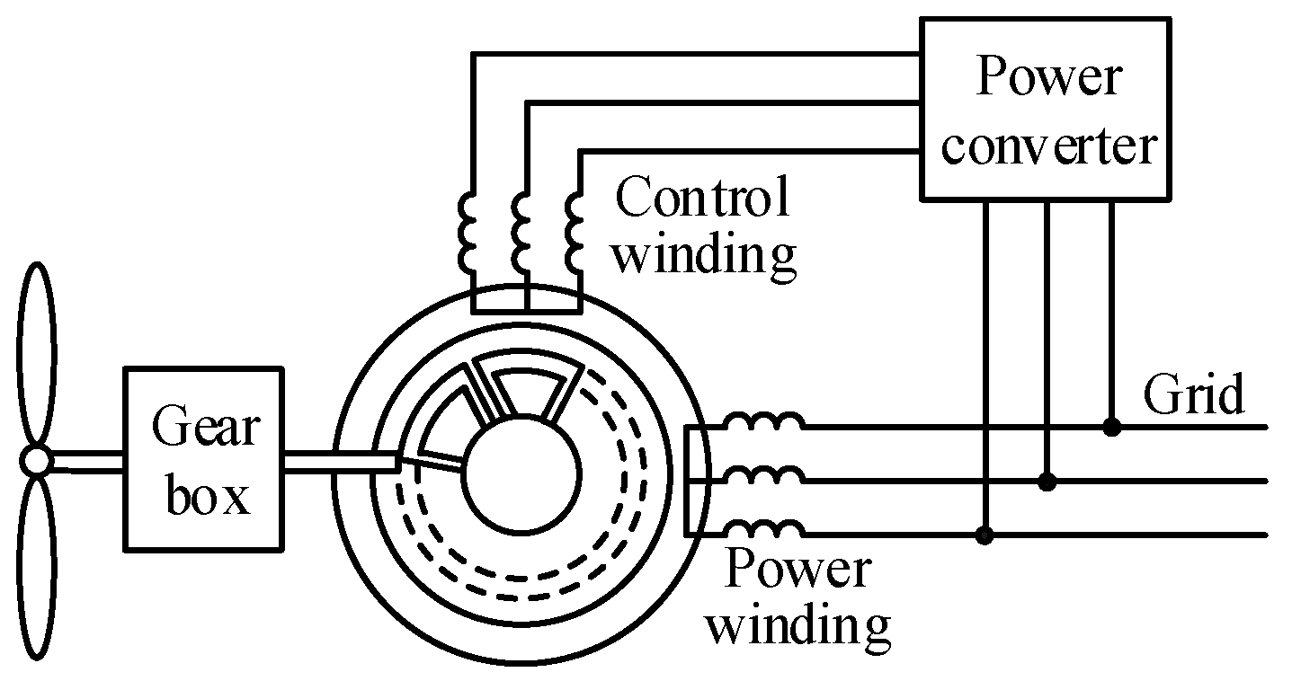
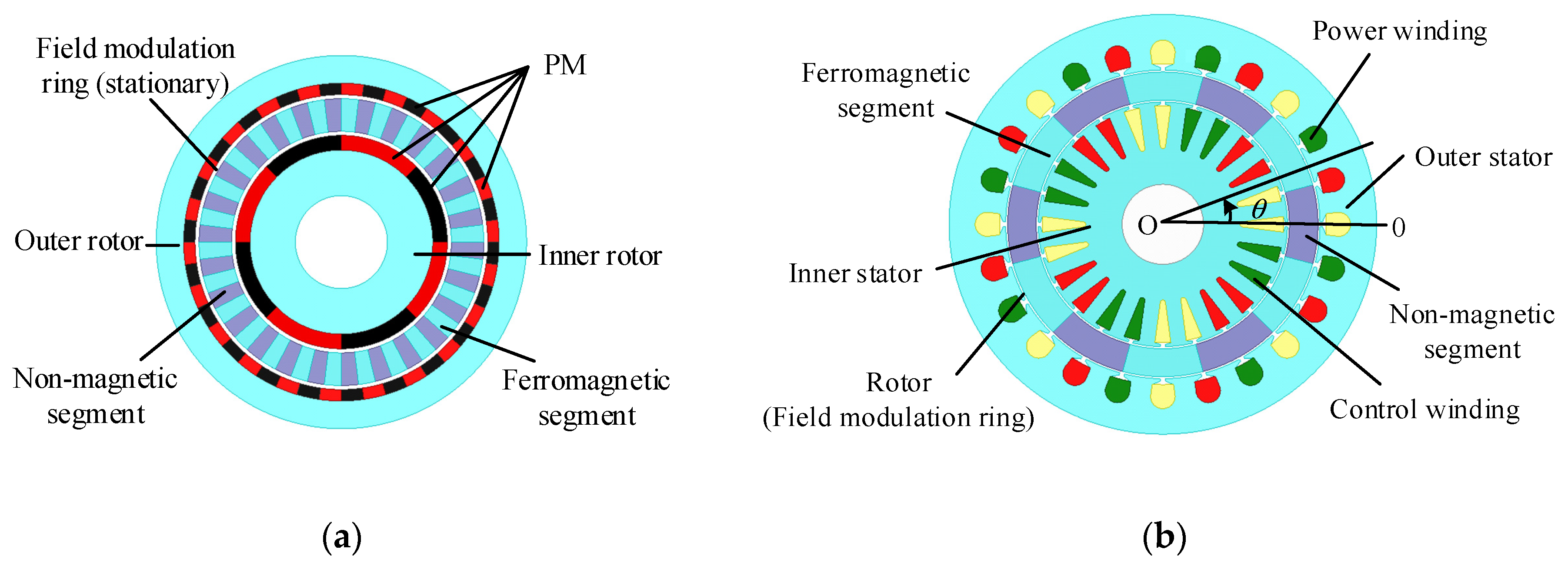
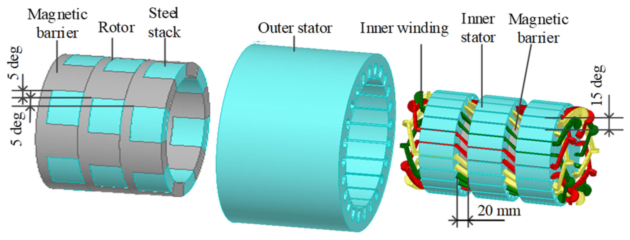
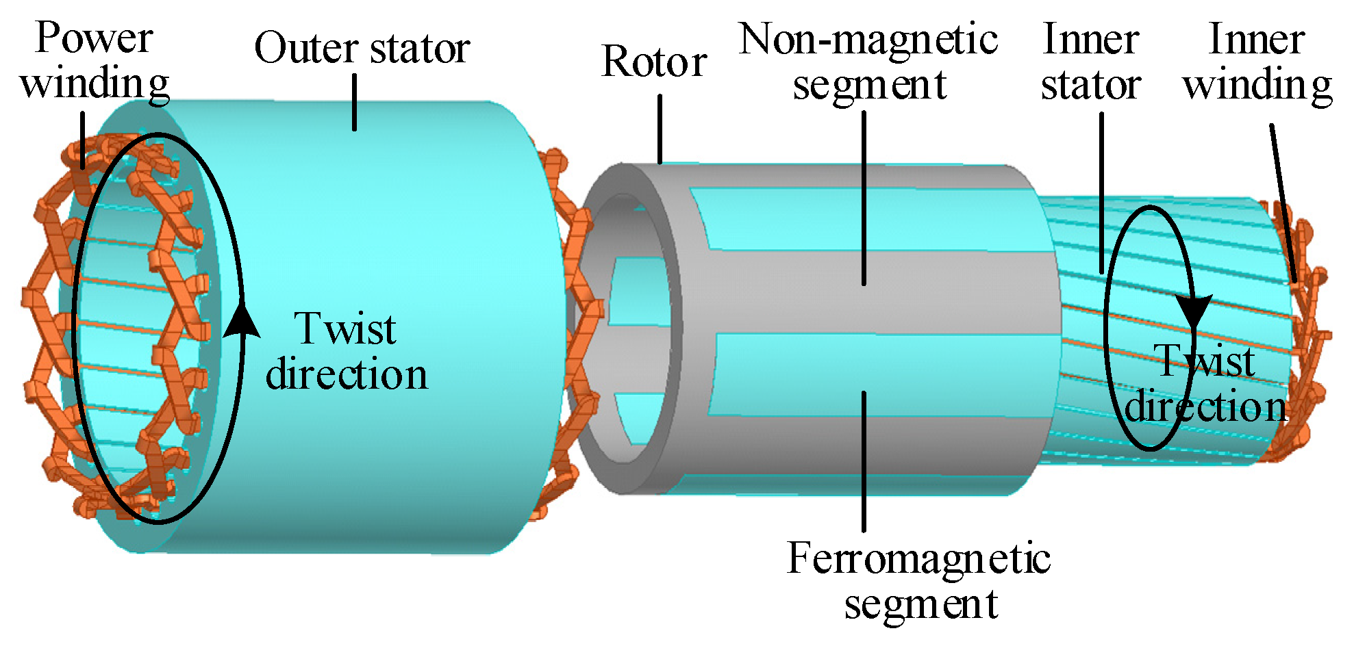
2.1. Topology of Brushless Doubly-Fed Generator with Dual Stators

Figure 4 illustrates the evolution of the BDFG with dual stators (BDFG-DS). The BDFG-DS evolved from the coaxial magnetic gear, which was firstly proposed by the British scholar D. Howe to improve the utilization rate of PM materials of traditional magnetic gears [17,18,19]. As seen in Figure 4a, the coaxial magnetic gear includes a stationary field modulation ring located centrally between the inner and outer rotors. In coaxial magnetic gears, the field modulation ring serves as the primary functional component, enabling torque transfer between the two permanent magnet (PM) rotors with different pole pair numbers through its field modulation effect, which is similar to that of the reluctance rotor used in traditional BDFGs [20,21,22,23,24]. But its mechanical structure is simpler than the rotor of a traditional BDFG. Figure 4b shows the structure of the BDFG-DS, featuring a modified coaxial magnetic gear design where dual stationary winding stators replace both the outer and inner PM rotors. And in the BDFG-DS, the field modulation ring becomes rotatable rather than fixed as in conventional magnetic gears. It is shown in Figure 4 that the circumferentially distributed field modulation ring comprises alternating ferromagnetic and non-magnetic segments. The BDFG-DS enables separate installation of the power and control windings on respective stators, providing more slot areas and higher electric load. Then the structure of the BDFG-DS is simpler and the power density is higher than that of the traditional BDFG.

2.2. Combination of Pole Pairs

The unmodulated ideal airgap flux density provided by AC current in both the power and control windings without the modulation ring can be written as follows [25]:
B p ( θ ) = F p Λ 0   cos ( p p ( θ ω p t + θ p 0 ) )
B c ( θ ) = F c Λ 0   cos ( p c ( θ ω c t + θ c 0 ) )
where Fp and Fc are the magnetomotive force (MMF) provided by the winding and control winding, respectively. Λ0 denotes the airgap permeance in per unit area. θ is the spatial angle position of a point in the airgap, as shown in Figure 4b. The rotating magnetic fields produced by the AC current in the power and control windings exhibit angular velocities ωp and ωc, respectively, with initial mechanical angular positions of θp0 and θc0.
The modulatory influence exerted by the modulation ring demonstrates functional equivalence to the magnetic field regulation achieved through the conventional BDFG’s reluctance rotor configuration, and they have the same modulation function [26,27,28,29], as follows:
λ ( θ ) = α +   2 sin ( α π ) π cos ( p r ( θ - ω r t + θ r 0 ) )                     + n = 2 + a n cos ( n p r ( θ - ω r t + θ r 0 ) )
where α is the duty ratio of the rotor and equals the circumferential width proportion between the ferromagnetic and non-magnetic segments. pr denotes the pole pair number of the rotor, which is numerically equivalent to the total count of ferromagnetic segments along the rotor periphery. ωr is the angular velocity of the rotor. θr0 is the initial mechanical angular position of the rotor. an is the Fourier coefficient. Then without considering high-order harmonics, the flux densities provided by the power and control windings through the modulation ring could be approximately considered as follows:
B p ( θ ) =   α μ 0 F p δ 1 + δ 2 cos [ p p ( θ ω p t + θ p 0 ) ]                       + μ 0 F p sin ( α π ) π ( δ 1 + δ 2 ) cos ( p p + p r ) θ ( p p ω p + p r ω r ) t + ( p p θ p 0 + p r θ r 0 )                       + μ 0 F p sin ( α π ) π ( δ 1 + δ 2 ) cos ( p p p r ) θ ( p p ω p p r ω r ) t + ( p p θ p 0 p r θ r 0 )
B c ( θ ) =   α μ 0 F c δ 1 + δ 2 cos [ p c ( θ ω c t + θ c 0 ) ]                       + μ 0 F c sin ( α π ) π ( δ 1 + δ 2 ) cos ( p c + p r ) θ ( p c ω c + p r ω r ) t + ( p c θ c 0 + p r θ r 0 )                       + μ 0 F c sin ( α π ) π ( δ 1 + δ 2 ) cos ( p c p r ) θ ( p c ω c p r ω r ) t + ( p c θ c 0 p r θ r 0 )
where δ1 and δ2 are the length of the inner and outer airgaps, respectively.
To achieve magnetic coupling between the power and control windings, it is necessary for space harmonics with the same pole pair number to be present in the terms of (4) and (5). Meanwhile, the space harmonic terms with the same pole pairs between (4) and (5) should have the same angular velocity to generate the torque stability. Then the rotor and power and control windings satisfy the following relationships:
p r = p p ± p c
ω r = p p ω p ± p c ω c p r
where + and − denote the sum modulation and differential modulation, respectively. Tp and Tc are defined as the electromagnetic torques exerted on the rotor by the power winding and control winding, respectively. According to (7) and the power conservation law:
T p T c = ± p p p c
In the sum modulation and differential modulation, the power and control windings exert electromagnetic torques on the rotor in the same direction and opposite direction, respectively. Meanwhile, according to (6) and (7), the sum modulation is ideal for low-speed, high-torque scenarios, while the differential modulation is best for high-speed, low-torque situations. Then in the wind power generation system, the sum modulation is adopted.

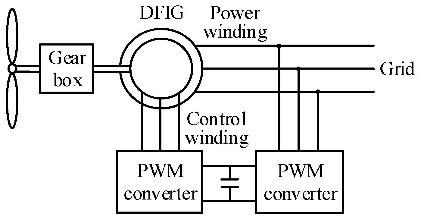
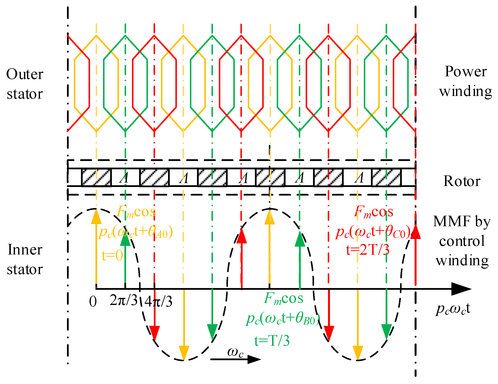
2.3. Operation Principle

Figure 5 illustrates that the BDFG-DS has the same electrical connections as that of the traditional BDFG system. As shown in Figure 5, the control winding in the inner stator is connected with the PWM converter, which is connected to the power grid, whereas the power winding of the outer stator is directly linked to the grid. Similar to the traditional BDFG, only a partial capacity converter is required, and its power rating depends on the wind turbine’s variable speed range. The bidirectional power converter’s capacity only requires merely 30% of the generator’s rating under equivalent speed regulation conditions as the DFIG [2].
Based on (7) and the adopted sum modulation, the speed of the rotor can be obtained as follows:
n r = 60 ( f p + f c ) p p + p c
where fp and fc denote the current frequency of the power and control windings, respectively. Obviously, although the rotor speed varies at different wind speeds, by adjusting the control winding current frequency, it is possible to ensure that the power winding emits electricity at a constant frequency. This characteristic makes the BDFG-DS particularly advantageous for implementing variable-speed constant-frequency energy conversion systems.
The mechanical motion equation of the BDFG-DS can be mathematically described as follows:
T r = T e m + J d ω r d t
T e m = T p + T c = 3 ( p p + p c ) L I p I c sin β
where L is the mutual inductance between the power and control windings. Ip and Ic denote the effective values of the current input to the power and control windings, respectively. β denotes the phase difference between the phase voltage and phase current. Based on (10) and (11), maximum power point tracking (MPPT) can be realized by adjusting the amplitude and phase of the control winding current.
The synchronous operational regime of the BDFG-DS is characterized by the rotor speed with direct current (fc = 0) inputting into the control winding, then (9) turns into:
n 0 = 60 f p p p + p c
s = n L n L 0 n L 0 = f c f p
Then the power transfer relationship between two sets of windings can be described as follows:
P c =     s P s
The BDFG-DS operates in three distinct modes: super-synchronous, synchronous, and sub-synchronous operation. Under elevated wind speed conditions, the BDFG-DS enters super-synchronous operational mode, where nL > nL0 and s > 0. In this operational mode, a dual-path energy transmission architecture is established. The mechanical energy provided by the wind turbine undergoes bifurcation into dual energy transmission pathways. The main energy stream is directly delivered to the electrical grid through the rotor assembly and power winding. Concurrently, the remaining energy transfer occurs through the rotor-coupled control winding mechanism, which functions in the electrical generation state and sends this energy into the grid through the inverter.
Under low wind velocity conditions, the BDFG-DS functions in sub-synchronous operational mode, where nL < nL0 and s < 0. During sub-synchronous operation, the control winding transitions to electric operation state, drawing electrical energy from the grid. This electrical energy, along with the mechanical energy input by the wind turbine, is sent to the power winding and ultimately to the grid. During synchronous operation, where nL = nL0 and s = 0, the control winding is only used to provide excitation and reactive current and it enters a non-participatory state in energy exchange.

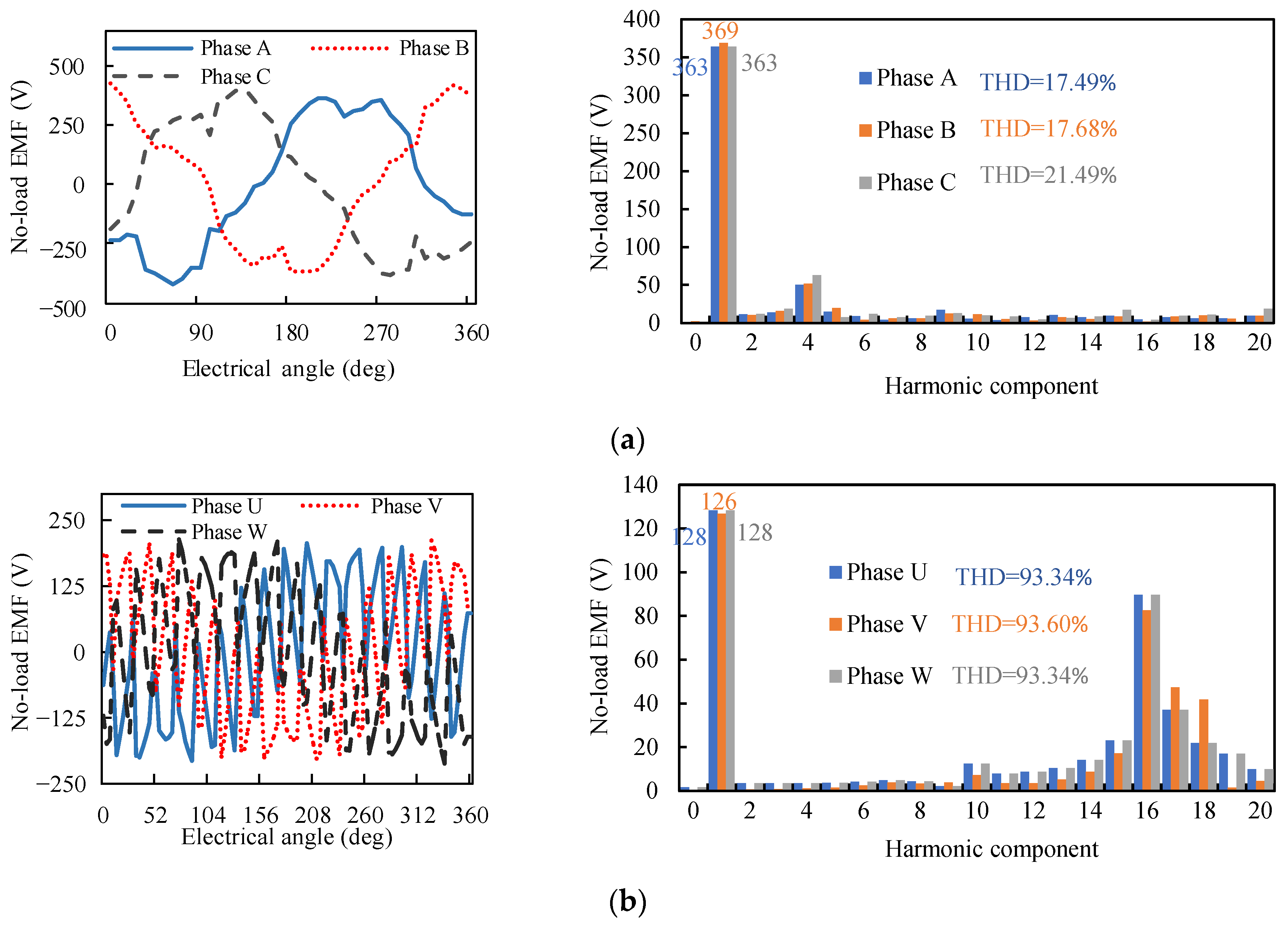
3. Asymmetric Phenomena

In order to illustrate the asymmetric phenomena, a BDFG-DS model was adopted, and according to (6), the magnetic pole configuration was specified with pp = 4, pc = 2, and pr = 6 for the power winding, control winding, and rotor, respectively. In order to obtain the root cause of the asymmetric phenomena and avoid the introduction of other factors, an enhanced design was developed, with the critical parameters systematically tabulated in Table 1. The configuration employed integer slot distributed windings to avoid the asymmetry effects by coil arrangements.
In order to eliminate the influence of control on the harmonics, space vector control was adopted, and a high control bandwidth current inner loop was used to ensure that the current had a high degree of sinuosity. As illustrated in Figure 6, when the rotor speed is 650 r/min, the no-load EMF waveforms of the BDFG-DS exhibits pronounced asymmetry in both the three-phase power and control windings. These waveforms also contain abundant harmonic components, which cannot be effectively mitigated through winding design.
Meanwhile, the torque ripple is definitely a problem, which is caused by the field modulation ring. The dominating reason for the torque ripple is the periodic variation of rotor reluctance. As illustrated in Figure 7, the relative position of the two stators also has a great influence on the torque ripple. As the teeth of one stator and the slot of the other stator become aligned, the cycle number of the torque ripple increases while its amplitude decreases.
In traditional electrical machines, even if there are a lot of harmonics in the EMF, the waveforms of three-phase EMF will still be symmetrical due to the symmetry of the three-phase magnetic circuit. Unlike the DIFG, the BDFG-DS has a rotor with a field modulation ring. To show the influence of the field modulation ring on the asymmetric phenomena, the excitation flux without a rotor is expressed as follows:
Φ j = F m Λ cos ( 2 π f p t + p p θ j )
where Φj is the excitation flux. j represents three-phase power winding, and it could be A, B or C. Fm is the peak value of the magnetomotive force (MMF) generated by current in the control winding. θj defines the angular displacement between the magnetomotive force (MMF) waveform and the reference axis (θj = 0), which coincides with the central axis of the three-phase power winding. Λ represents the airgap permeance. Since the three-phase magnetic circuits are symmetrical and the same excitation MMF is used, consistency is guaranteed among the induced EMF waveforms of the three-phase power winding, with only a phase difference of 120 electrical degrees.
However, the situation in the BDFG-DS is different. According to (7), due to the change in rotor speed, the MMF generated by the current of the control winding cannot keep rotating at a synchronous speed with the power winding and is even stationary under rated working conditions, as shown in Figure 8. According to Figure 8, the three-phase excitation magnetic circuit is asymmetric, which directly leads to the asymmetry of the no-load EMF of the three-phase winding. The three-phase excitation magnetic flux can be expressed as follows:
Φ j = F j Λ j cos ( 2 π f p t + p p θ j 0 p r θ r 0 + p c θ c 0 )
F j = 2 π T T 0 T 0 + T F m | cos [ 2 π f c t + p c ( θ j 0 θ c 0 ) ] | d t
where Fj represents the MMF created by the current of the control winding. Λj represents the magnetic permeance of three-phase magnetic circuit. T = 1/fp represents the grid period and T0 is one of its initial times. θj0 represents the position angle of the three-phase power winding central axis, and there is a mechanical angle of 120°/pp between θA0, θB0, and θC0. θr0 represents the position angle of the rotor at T0. θc0 represents the position angle of the MMF generated by the control windings at T0. According to (7), ppθj0 + prθr0pcθc0 is a constant value, and then the phase of three-phase excitation magnetic circuit is symmetrical. According to (17), the excitation MMFs of the three-phase power windings (Fj) are different; therefore, the three-phase magnetic flux of the power windings are asymmetrical.

4. Improvements

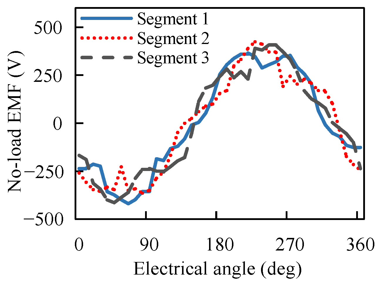
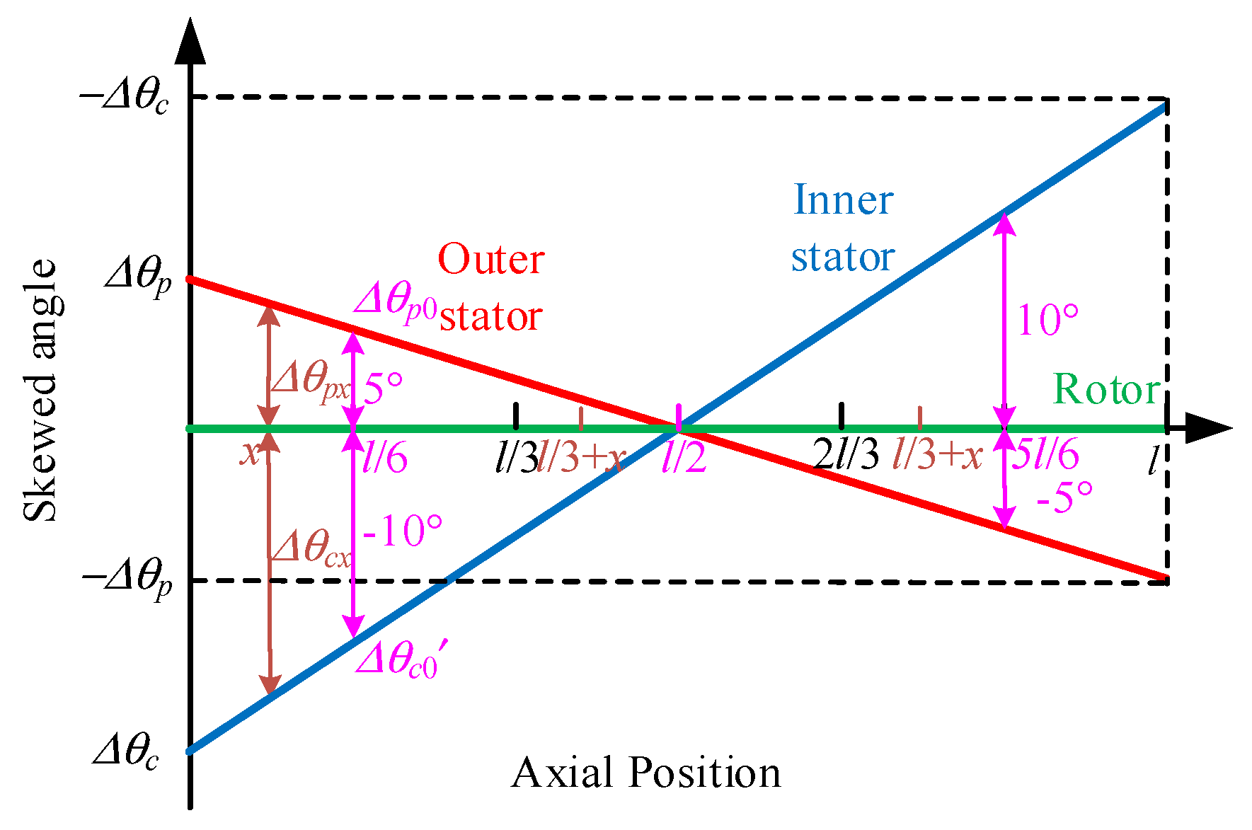
4.1. Axial Segmented Skewed Pole Structure

According to (17), only when one of the following two conditions is met are the excitation MMFs of the three-phase power windings (Fj) the same, and the asymmetry problem can be solved. The two conditions are:
f c = n 2 f p ,         n = 1 , 2 , 3 ,
| θ A 0 θ c 0 | = | θ B 0 θ c 0 | = | θ C 0 θ c 0 | | θ j 0 θ c 0 | π
According to the working principle of the BDFG-DS, the frequency of the control winding current (fc) is constantly changing with the change in wind speed, then the condition (18) cannot be met. Although condition (19) cannot be met due to the difference in the pole pair numbers between the power and control windings, the method of axial segmented skewed poles can be adopted to ensure that the three segments meet this condition. For example, by rotating the three segments by an appropriate angle, condition 2 can be satisfied between the A phase of the first segment and the B phase of the second segment and the C phase of the third segment, as shown in Figure 9. According to Figure 9, simply dividing the inner stator into three segments along the axial direction and then rotating the second and third segments in the same direction by 30 and 60 degrees, respectively, can realize symmetry of the three-phase magnetic circuit. For example, phase A corresponds to the first segment, phase C corresponds to the second segment, and phase B corresponds to the third segment. This method is also applicable to multi-phase motors, where the segment count should match the phase count.
Considering the bipolar nature of the motor, the skewed pole angle can actually be chosen to be smaller, only half of it is needed, as shown in the Figure 10. By deduction, the skewed pole angles for different pole pairs are given as follows:
Δ θ c 0 = min | 3 m p p - n p c | × 60 p p p c ( deg ) > 0 n 3 l ,       m , n , l = 0 , 1 , 2 , 3        
where Δθc0 is the skewed pole angle of each segment of the inner stator, and it can be calculated that for a BDFG-DS with the 4P/2P configuration, Δθc0 should be taken as 15 degrees.
Due to the use of the axial segmented skewed pole structure, the no-load EMF of the BDFG-DS will decrease, and the reduction rate is expressed as follows:
γ = 2 3 1 - cos p c Δ θ c 0 × 100 %
Then, the no-load EMF of the BDFG-DS will decrease by 8.93%. To eliminate the adverse impacts caused by axial segmented skewed poles of the inner stator, according to (16), the rotor also adopts the segmented skewed pole structure, and the relationship between the skewed pole angles of each segment of the rotor and the inner stator is as follows:
Δ θ r 0 = p c Δ θ c 0 / p r
where Δθr0 is the skewed pole angle of each segment of the rotor. If the value of Δθc0 is 15 degrees, since pc = 2 and pr = 6, Δθr0 should take a value of 5 degrees.
The structure of the BDFG-DS with the axial segmented skewed pole is shown in Figure 11. In order to reduce inter segment magnetic flux leakage and facilitate wire embedding, a magnetic barrier is added between segments. The finite element simulation is used to analyze the no-load EMF for the three segments of the A-phase power winding. In order to improve simulation efficiency, 2D simulation modeling was adopted. By establishing three simulation models based on the initial position relationship of the stators and rotor in the three segments, the no-load EMF can be solved, as shown in Figure 12. By comparison with Figure 6a, it is found that the three EMF waveforms under the three segments are the same as the three-phase waveforms of the BDFG-DS without the segmented structure, and the three EMF waveforms under the three segments have the same phase, no longer differing by 120 degrees in electrical angle from each other. Therefore, the three-phase power winding no-load EMF, after using the axial segmented skewed pole structure, is 1/3 of the sum of the pre-segmented three-phase no-load EMFs shifted to the same phase. Then three-phase symmetry is achieved, as shown in Figure 13. By comparing Figure 6 and Figure 13, it can be observed that the segmented skewed pole structure significantly reduces the harmonics, while the fundamental component of the no-load EMFs does not decrease due to skewing.
According to the speed range requirements, there can be multiple combinations of pole pairs for the BDFG-DS. The segmented skewed pole angle structure mentioned above is proposed for the BDFG-DS with 4P/2P configuration. Without loss of generality, for different pole pair configurations, the method for calculating the segmented skewed pole angles are categorized into three situations, as shown in Table 2.

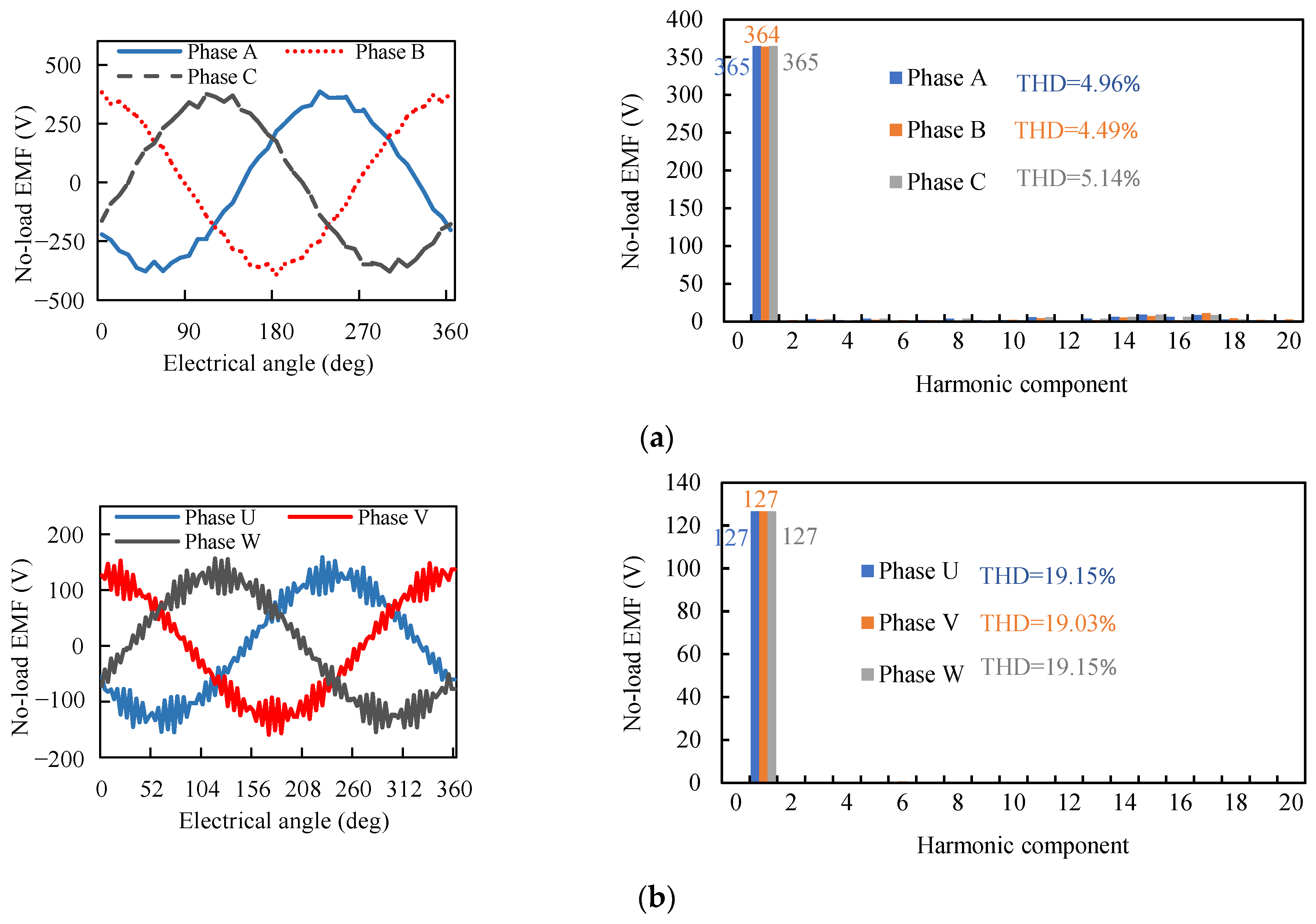
4.2. Complementary Skewed Stators

While the axial segmented skewed pole configuration in the BDFG-DS effectively mitigates the asymmetric phenomena, the existence of a magnetic barrier increases the end winding length, which reduces the power density, increases the copper loss and used copper amount, and leads to lower efficiency. As shown in Figure 13, the segmented structure could effectively reduce the harmonics; however, the harmonic contents in the no-load EMF waveforms of the two sets of windings are not small enough.
To address these problems and minimize the harmonics as much as possible, combined with traditional skewed slots, optimization with complementary skewed stators is proposed.
According to (16), the phase angle of the EMF will not be changed when the position change of the two stators and rotor satisfies the following relationship:
p p Δ θ p 0 = p r Δ θ r 0 - p c Δ θ c 0
where Δθp0, Δθ′r0, and Δθ′c0 are the position changes of the outer stator, rotor, and inner stator, respectively. If Δθ′r0 = 0, the outer stator should be divided into three segments according to (23), and the following relationship should be satisfied:
p p Δ θ p 0 = p c Δ θ c 0
Then the phase angles of the EMFs of the power and control windings at three segments are the same. According to Figure 10 and (24), the angle differences among the three segments are Δθp0 = 5 degrees and Δθ′c0 = −10 degrees.
Setting Δθ′r0 = 0, the rotor does not need to be segmented and it is convenient to manufacture. However, the coil still needs to change slots among three segments of two stators, which leads to difficulty in assembling the coil, longer end winding, and larger axial length. From a geometric decomposition perspective, traditional skewed slot configurations essentially comprise axially distributed straight laminations exhibiting controlled circumferential displacement. On the contrary, the segmented stator could also be regarded as a skewed slot, as shown in Figure 13, where Δθc and Δθp are the skewing slot angles of the inner stator and outer stator, respectively; l is the axial length of the BDFG-DS; x is the position of any point along the axis; and Δθpx and Δθcx are the skewing angles of the outer and inner stator at x, respectively. Along the axis, the BDFG-DS is uniformly divided into three segments, and their ranges are [0, l/3], [l/3, 2l/3], and [2l/3, l], respectively. And the angle positions of the three segmented stators are equal to the skewed angle at l/6, l/2, and 5l/6, respectively. Adopting a skewed slot stator, for any point x in [0, l/3], there will be corresponding points (l/3 + x) and (2l/3 + x) in [l/3, 2l/3] and [2l/3, l], respectively, where the skewed angles of two stators satisfied (24), as shown in Figure 14. And according to Figure 14, the skewed angles of two stators satisfy the following conditions:
Δ θ p = 3 2 Δ θ p 0 Δ θ c = 3 2 Δ θ c 0 Δ θ p 0 - Δ θ c 0 = Δ θ c 0
where Δθc0 can be calculated according to the Table 2. Substituting (24) into (25) gives:
Δ θ p = 3 p c 2 ( p p + p c ) Δ θ c 0 Δ θ c = 3 p p 2 ( p p + p c ) Δ θ c 0
According to (26), if pc = 2 and pp = 4, Δθp = 7.5 degrees and Δθc = −15 degrees. Figure 15 shows the structure of the BDFG-DS with complementary skewed stators, where both the two stators and rotor are all only one segment. The two stators are twisted in the opposite direction and different angles, and the complementary structure is formed to avoid the change in phase angle. Adopting the complementary skewed stators not only cancels the symmetrical phenomena but also greatly reduces the harmonics, as shown in Figure 16. By this method, the EMF waveforms of the power and control windings are both very sinusoidal. Comparing Figure 16 with Figure 6 and Figure 13, it can be observed that the BDFG with complementary skewed stators has the lowest harmonic content and the fundamental component of the no-load EMFs does not decrease due to skewing.
To eliminate the influence of control actions on torque pulsations and isolate the torque ripple caused solely by the inherent structure of the BDFG-DS, a 15 Hz, 1.4 A sinusoidal current was injected into the control winding while a 50 Hz, 2.1 A sinusoidal current was supplied to the power winding. Under these conditions, the magnetic flux density distribution is shown in Figure 17. Figure 18 comparatively illustrates the torque waveforms of the BDFG-DS with different structural configurations when the rotor was at 650 rpm. The BDFG-DS without a segmented or skewed structure exhibits significant torque ripples (±8 N∙m) caused by the field modulation ring. As shown in Figure 17, the segmented structure could effectively reduce torque ripples to about ± 1.5 N∙m, and the complementary skewed structure could greatly reduce the torque ripples to only ±0.3 N∙m. Meanwhile, the effective torque (20 N∙m) remains unchanged after using the segmented or complementary skewed structure. Without segments, adopting the complementary skewed stators, the power density of the BDFG-DS did not decrease and the efficiency was improved.
Whether adopting complementary skewed stators or the segmented structure, integer slot winding should be selected for both the power and control windings; otherwise, the asymmetric phenomena will be more serious and the skewed angles will be the multiple of the angle in Table 2. Moreover, the fractional slot will reduce the winding coefficient. This is not suitable for the optimization method in this paper.

5. Conclusions

This paper presents intensive studies on the asymmetric phenomena of a three-phase BDFG-DS with a reluctance rotor based on an analysis of the working mechanism and points out the root cause of the asymmetric phenomena, that is, the asymmetrical magnetic circuit. Then two improvement methods, a segmented structure and complementary skewed stators, are proposed. Approaches to addressing the asymmetrical problem are proposed in detail by the theoretical analyses. The simulation results show that the asymmetric phenomena could be effectively solved by using the segmented structure or complementary skewed stators. At the same time, the torque ripple can be significantly minimized without a reduction in the average torque. As the complementary skewed stators do not need to increase the axial length, then the torque density, power density, and efficiency are not decreased, and the structure of the BDFG-DS is quite simple and easy to manufacture.

Author Contributions

Conceptualization, Y.J. and K.W.; methodology, Y.J. and K.W.; validation, L.Z., W.Z. and Z.H.; formal analysis, Y.J. and K.W.; investigation, L.Z.; writing—original draft preparation, Y.J., K.W. and L.Z.; writing—review and editing, W.Z. and Z.H.; supervision, Y.J.; project administration, Y.J.; funding acquisition, Y.J. All authors have read and agreed to the published version of the manuscript.

Funding

This research was funded in part by the Open Research Fund of Jiangsu Collaborative Innovation Center for Smart Distribution Network, Nanjing Institute of Technology (Grant No. XTCX202308), the Foundation of Jiangsu Provincial Double-Innovation Doctor Program under Grant No. (2020) 30639, and the Natural Science Research Start-up Foundation of Recruiting Talents of Nanjing University of Posts and Telecommunications (Grant No. NY219154).

Data Availability Statement

Data are contained within the article.

Conflicts of Interest

Author Lingkang Zhou was employed by the company Weifu High-Technology Group Co., Ltd. The remaining authors declare that the research was conducted in the absence of any commercial or financial relationships that could be construed as a potential conflict of interest.

References

  1. Ma, Y.; Zhu, D.; Hu, J.; Liu, R.; Zou, X.; Kang, Y. Optimized design of demagnetization control for dfig-based wind turbines to enhance transient stability during weak grid faults. IEEE Trans. Power Electron. 2025, 40, 76–81. [Google Scholar] [CrossRef]
  2. Li, Z.; Xie, Z.; Zhang, X. An improved strategy of grid-forming dfig based on disturbance rejection stator flux control. IEEE Trans. Ind. Electron. 2024, 71, 2498–2509. [Google Scholar] [CrossRef]
  3. Liu, X.; Zhang, Z.; Liu, Y.; Yuan, L.; Su, M.; Zhou, F.; Li, C.; Liu, J.; Zhang, X.; Wang, P. Fault current multi-stages calculation method for dfig-based wind farms with whole fault process attributes under asymmetrical grid fault conditions. IEEE Trans. Sustain. Energ. 2024, 15, 2361–2379. [Google Scholar] [CrossRef]
  4. Rani, M.A.A.; Chakkarapani, M.; Nagamani, C.; Ilango, G.S. An Improved Angular Stator Flux Frequency Computation Method for Robust MPPT Operation of DFIG Under Unbalanced Grid Voltage. IEEE Trans. Ind. Appl. 2023, 59, 1162–1174. [Google Scholar] [CrossRef]
  5. Yang, R.H.; Jin, J.X. Unified power quality conditioner with advanced dual control for performance improvement of dfig-based wind farm. IEEE Trans. Sustain. Energ. 2021, 12, 116–126. [Google Scholar] [CrossRef]
  6. Zeng, Y.; Cheng, M.; Zhang, C. Investigation of cascaded and modulated rotors for dual-stator brushless doubly-fed machines. IEEE Trans. Energy Conver. 2024, 39, 344–355. [Google Scholar] [CrossRef]
  7. Cai, D.; Liu, H.; Hu, S.; Sun, G.; Wang, E.; Tang, J. A proportional-integral-resonant current control strategy for a wind-driven brushless doubly fed generator during network unbalance. Electronics 2024, 13, 1616. [Google Scholar] [CrossRef]
  8. Chen, X.; Pan, W.; Wang, X.; Zhou, Y. Design of a brushless doubly fed generator with simplified three-phase wound rotor. IEEE Trans. Ind. Electron. 2023, 70, 4427–4439. [Google Scholar] [CrossRef]
  9. Wen, H.; Shao, Y.; Shuai, Z.; Cheng, M. Performance analysis of a brushless doubly fed machine with asymmetrical composite flux barrier/magductance rotor. IEEE Trans. Ind. Electron. 2024, 71, 6699–6708. [Google Scholar] [CrossRef]
  10. Zhang, D.; Ma, J.; Yu, N.; Wang, S.; Lu, H. Research on control-winding-current orientation control for grid-connected brushless doubly fed induction generation system. IEEE Trans. Ind. Appl. 2023, 59, 5919–5931. [Google Scholar] [CrossRef]
  11. Yan, X.; Cheng, M. Backstepping-based direct power control for dual-cage rotor brushless doubly fed induction generator. IEEE Trans. Power Electron. 2023, 38, 2668–2680. [Google Scholar] [CrossRef]
  12. Liu, H.; Zhang, Y.; Zhang, F.; Jin, S.; Zhang, H.; Nian, H. Design and performance analysis of dual-stator brushless doubly-fed machine with cage-barrier rotor. IEEE Trans. Energy Conver. 2019, 34, 1347–1357. [Google Scholar] [CrossRef]
  13. Zeng, Y.; Cheng, M.; Wei, X.; Xu, L. Dynamic modeling and performance analysis with iron saturation for dual-stator brushless doubly fed induction generator. IEEE Trans. Energy Conver. 2020, 35, 260–270. [Google Scholar] [CrossRef]
  14. Han, P.; Cheng, M.; Wei, X.; Jiang, Y. Steady-state characteristics of the dual-stator brushless doubly-fed induction generator. IEEE Trans. Ind. Electron. 2018, 65, 200–210. [Google Scholar] [CrossRef]
  15. Jiang, Y.; Zhang, J.; Li, T. A segmented brushless doubly fed generator for wind power applications. IEEE Trans. Magn. 2018, 54, 1–4. [Google Scholar] [CrossRef]
  16. Zhu, Z.Q. Overview of novel magnetically geared machines with partitioned stators. IET Electr. Power Appl. 2018, 12, 595–604. [Google Scholar] [CrossRef]
  17. Gardner, M.C.; Johnson, M.; Toliyat, H.A. Analysis of high gear ratio capabilities for single-stage, series multistage, and compound differential coaxial magnetic gears. IEEE Trans. Energy Conver. 2019, 34, 665–672. [Google Scholar] [CrossRef]
  18. Lee, S.H.; Im, S.Y.; Ryu, J.Y.; Lim, M.S. Optimum design process of coaxial magnetic gear using 3d performance prediction method considering axial flux leakage. IEEE Trans. Ind. Appl. 2024, 60, 3075–3085. [Google Scholar] [CrossRef]
  19. Praslicka, B.; Gardner, M.C.; Johnson, M.; Toliyat, H.A. Review and analysis of coaxial magnetic gear pole pair count selection effects. IEEE J. Emerg. Sel. Topics Power Electron. 2022, 10, 1813–1822. [Google Scholar] [CrossRef]
  20. Jing, L.; Tang, W.; Wang, T.; Ben, T.; Qu, R. Performance analysis of magnetically geared permanent magnet brushless motor for hybrid electric vehicles. IEEE Trans. Transp. Electrific. 2022, 8, 2874–2883. [Google Scholar] [CrossRef]
  21. Bai, J.; Liu, J.; Zheng, P.; Tong, C. Design and analysis of a magnetic-field modulated brushless double-rotor machine—Part i: Pole pair combination of stator, pm rotor and magnetic blocks. IEEE Trans. Ind. Electron. 2019, 66, 2540–2549. [Google Scholar] [CrossRef]
  22. Liu, J.; Bai, J.; Liu, G.; Wang, Y.; Zheng, P. Investigation of an integrated magnetic-field-modulated brushless double-rotor machine with an improved pm rotor. IEEE Trans. Magn. 2021, 57, 1–6. [Google Scholar] [CrossRef]
  23. Xu, X.; Zhang, W.; Cheng, J.; Zhao, J.; Qian, F. Design and optimization of axial field flux-switching magnetic gear composite motor based on varying-network magnetic circuit. IEEE Access 2023, 11, 53749–53759. [Google Scholar] [CrossRef]
  24. Kumashiro, A.; Chen, L.; Fujii, Y.; Chiba, A.; Gruber, W.; Amrhein, W.; Jungmayr, G. Novel reluctance-type magnetic-geared motor integrated with high-speed bearingless motor. IEEE Trans. Ind. Appl. 2024, 60, 3808–3819. [Google Scholar] [CrossRef]
  25. Mathekga, M.E.; Ademi, S.; McMahon, R.A. Brushless doubly fed machine magnetic field distribution characteristics and their impact on the analysis and design. IEEE Trans. Energy Conver. 2019, 34, 2180–2188. [Google Scholar] [CrossRef]
  26. Cheng, M.; Han, P.; Hua, W. General airgap field modulation theory for electrical machines. IEEE Trans. Ind. Electron. 2017, 64, 6063–6074. [Google Scholar] [CrossRef]
  27. Chen, H.; EL-Refaie, A.M.; Zuo, Y.; Cai, S.; Tang, J.; Liu, Y. A permanent magnet brushless doubly fed electric machine for variable–speed constant–frequency wind turbines. IEEE Trans. Ind. Electron. 2023, 70, 6663–6674. [Google Scholar] [CrossRef]
  28. Cheng, M.; Wen, H.; Han, P.; Zhu, X. Analysis of airgap field modulation principle of simple salient poles. IEEE Trans. Ind. Electron. 2019, 66, 2628–2638. [Google Scholar] [CrossRef]
  29. Zhang, J.; Jiang, Y.; Hu, X.; Xu, S. A brushless doubly fed generator based on permanent magnet field modulation. IEEE Trans. Ind. Electron. 2020, 67, 3505–3516. [Google Scholar] [CrossRef]
Figure 1. DFIG-based variable-speed wind power generation system.
Electronics 14 01649 g001
Figure 2. Brushless doubly-fed generator-based variable-speed wind power generation system.
Electronics 14 01649 g002
Figure 3. The rotor structures of the brushless doubly-fed generator: (a) cage rotor; (b) reluctance rotor.
Electronics 14 01649 g003
Figure 4. Evolution of the brushless doubly-fed generator (BDFG) with a double stator: (a) coaxial magnetic gear; (b) BDFG with a double stator.
Electronics 14 01649 g004
Figure 5. The electrical connections of the brushless doubly-fed generator with dual stators.
Electronics 14 01649 g005
Figure 6. No-load EMF waveforms and THD of the brushless doubly-fed generator with dual stators: (a) power windings; (b) control windings.
Electronics 14 01649 g006
Figure 7. Torque ripple characteristics under variable stator alignment configurations.
Electronics 14 01649 g007
Figure 8. Asymmetry phenomena of brushless doubly-fed generator with dual stators.
Electronics 14 01649 g008
Figure 9. Schematic diagram of axial segmented skewed poles method.
Electronics 14 01649 g009
Figure 10. Revised scheme of the axial segmented skewed poles method.
Electronics 14 01649 g010
Figure 11. The structure of the brushless doubly-fed generator with dual stators with the axial segmented skewed pole.
Electronics 14 01649 g011
Figure 12. No-load EMF waveforms of phase A corresponding to different segments.
Electronics 14 01649 g012
Figure 13. No-load EMF waveforms and THD of the brushless doubly-fed generator with dual stators with the axial segmented skewed pole structure: (a) power winding; (b) control winding.
Electronics 14 01649 g013
Figure 14. Complementary skewed angles of two stators.
Electronics 14 01649 g014
Figure 15. Structure of the brushless doubly-fed generator with complementary skewed stators.
Electronics 14 01649 g015
Figure 16. No-load EMF waveforms and THD of the brushless doubly-fed generator with dual stators with complementary skewed stators: (a) power winding; (b) control winding.
Electronics 14 01649 g016aElectronics 14 01649 g016b
Figure 17. Magnetic flux density distribution of the brushless doubly-fed generator with dual stators.
Electronics 14 01649 g017
Figure 18. Electromagnetic torque of the brushless doubly-fed generator with dual stators.
Electronics 14 01649 g018
Table 1. Design parameters of the brushless doubly-fed generator with dual stators.
ParameterValue
Outer diameter of outer stator 210 mm
Inner diameter of outer stator 154.4 mm
Outer air gap length0.5 mm
Thickness of rotor14 mm
Inner airgap length0.5 mm
Inner diameter of inner stator41 mm
Stack length 150 mm
Polar arc coefficient of rotor (α)0.5
Number of outer stator slot24
Number of inner stator slot24
Turns per slot of power winding120
Turns per slot of control winding80
Pole pairs of power winding (pp)4
Pole pairs of control winding (pc)2
Pole pairs of rotor (pr)6
Iron materialDW360-50
Rated speed (n0)500 rpm
Rated power of power winding 1 kW
Rated power of control winding 300 W
Table 2. The segmented skewed pole angles of the brushless doubly-fed generator with dual stators with different pole pair numbers.
SituationPole Pair NumbersSegmented Skewed Pole Angles
Situation 1 p p = n p r 6     n 3 l ,                   n ,   l = 1 , 2 , 3 ,     Δ θ c 0 = x = min 3 m p p n p c 60 p p p c     Δ θ r 0 = t = p c Δ θ c 0 p r m , n , l = 1 , 2 , 3 ,                 n 3 l  
Situation 2 p p = n p c 3     n 3 l ,                   n ,   l = 1 , 2 , 3 ,     Δ θ r 0 = t = min 6 m p p n p r 60 p p p r   Δ θ c 0 = p r Δ θ r 0 p c m , n , l = 1 , 2 , 3 ,                 n 3 l    
Situation 3The others   Δ θ r 0 = max p c x p r , t   Δ θ c 0 = p r Δ θ r 0 p c  
Disclaimer/Publisher’s Note: The statements, opinions and data contained in all publications are solely those of the individual author(s) and contributor(s) and not of MDPI and/or the editor(s). MDPI and/or the editor(s) disclaim responsibility for any injury to people or property resulting from any ideas, methods, instructions or products referred to in the content.

