Article

A Wideband Digital Pre-Distortion Algorithm Based on Edge Signal Correction

1
School of Information Engineering, Anhui Broadcasting Movie and Television College, Hefei 230011, China
2
School of Electronics and Information Engineering, Anhui University, Hefei 230601, China
*
Author to whom correspondence should be addressed.
Electronics 2025, 14(11), 2170; https://doi.org/10.3390/electronics14112170
Submission received: 14 March 2025 / Revised: 19 May 2025 / Accepted: 20 May 2025 / Published: 27 May 2025
(This article belongs to the Section Circuit and Signal Processing)

Abstract

With the continuous expansion of communication bandwidth, accurately modeling the non-linear characteristics of power amplifiers has become increasingly challenging, directly affecting the performance of digital pre-distortion (DPD) technology. The high peak-to-average power ratio and complex modulation schemes of wideband signals further exacerbate the difficulty of DPD implementation, necessitating more efficient algorithms. To address these challenges, this paper proposes a wideband DPD algorithm based on edge signal correction. By acquiring signals near the center frequency and comparing them with equally band-limited feedback signals, the algorithm effectively reduces the required processing bandwidth. The incorporation of cross-terms for model calibration enhances the model fitting accuracy, leading to significant improvement in pre-distortion performance. Simulation results demonstrate that compared with traditional DPD algorithms, the proposed method reduces the error vector magnitude (EVM) from 1.112% to 0.512%. Experimental validation shows an average improvement of 11.75 dBm in adjacent channel power at a 2 MHz frequency offset compared to conventional memory polynomial DPD. These improvements provide a novel solution for power amplifier linearization in wideband communication systems.

1. Introduction

With the advancement of 5G commercialization, key performance indicators in mobile communications, such as transmission rate, latency, network capacity, connection density, and energy efficiency, have achieved significant progress. Further enhancements in mobile communication capabilities provide essential technical support for innovative applications like autonomous vehicles and remote medical surgeries [1]. However, one of the most critical radio frequency (RF) components in mobile communications—the Radio Frequency Power Amplifier (RF PA)—often exhibits non-linear characteristics under high input voltages. This results in deviations between the output-to-input voltage ratio and the standard gain of the RF PA. Such non-linear distortion not only degrades the transmission quality of mobile signals but also interferes with other channels, causing severe performance and entire communication system losses [2].
Digital Pre-Distortion (DPD) technology is the preferred strategy for linearizing RF Pas [3]. The widespread adoption of this technology is primarily due to its significant advantages in cost-effectiveness, low power consumption, and ease of integration. The fundamental principle of DPD involves calculating a non-linear distortion model based on both the amplified signal and the original signal. An inverse pre-distortion is then applied to the source signal to counteract the inherent non-linear effects of the power amplifier [4]. When the pre-distorted signal passes through the power amplifier, near-ideal linear amplification can be achieved. Thus, the transmission quality and the reliability of wireless communications can be significantly improved [5]. However, as the data transmission rates increase, and the bandwidth of modulated signals expands, the amount of data that DPD algorithms must process also rises [6]. Traditional DPD designs are already unable to effectively handle data bandwidths exceeding hundreds of megahertz. The rapidly increasing computational demands associated with wideband signals present new challenges for DPD design.
In the wideband network, the precision of DPD implementation must be continuously enhanced to meet the increasing demands for bandwidth and sampling rates [7]. The significant rise in data volume and computational complexity not only intensifies the technical challenges of implementation but also imposes stringent requirements on hardware performance. Consequently, developing a DPD algorithm, which is capable of effectively managing wideband signals, becomes especially crucial. The objective is to ensure accurate signal processing while substantially reducing the system’s computational load [8]. This approach offers an efficient solution for signal linearization in wideband communication systems.
Traditional DPD techniques often incur substantial computational loads and exhibit inadequate processing accuracy when calculating model coefficients for wideband signals. Reference [2] proposed a sub-sampling DPD scheme utilizing harmonic mixing; however, it failed to account for the impact of missing signals on the model. To address performance degradation caused by non-ideal characteristics, reference [9] introduced a DPD method that jointly compensates for non-ideal characteristics at both the modulation and demodulation stages. Nonetheless, it did not thoroughly investigate the algorithm itself, rendering it unsuitable for wideband signals. Some researchers have segmented the power amplifier’s amplitude into multiple sections, performing low-order modeling on each segment [10]. This approach can reduce the order of the band-limited model and the condition number of the band-limited matrix to some extent, but it remains inadequate for modeling wideband communication scenarios. Linearization around the center frequency is a critical consideration for the performance of wideband signal power amplifiers. Reference [11] employed a low-speed Analog-to-Digital Converter (ADC) to sample the feedback signal. Subsequently, some signal processing techniques are used to reconstruct the power amplifier’s output signal near the original high sampling rate. However, the DPD model derived from this method suffers from poor fitting performance and requires specific comb-shaped integrators with stringent implementation conditions. Reference [12] considered edge signals outside the center frequency to estimate model parameters, enabling the algorithm to linearize higher bandwidth signals. Nevertheless, this algorithm does not directly process signals near the center frequency, resulting in low model fitting accuracy and insufficient linearization performance in highly non-linear environments. Reference [13] eliminated the band-pass filter and utilized a resampling module to continuously adjust the sampling rate to achieve the optimal rate suitable for the model. However, due to neglecting the issue of power leakage, non-linear effects are exacerbated in multi-channel communication systems.
In summary, current DPD methods for linearizing wideband signals mostly employ down-sampling techniques to reduce the amount of data processed. While this approach somewhat decreases computational complexity, it overlooks the impact of unsampled signals on the model, leading to poor model fitting, reduced stability, and lower communication transmission quality.
To address the aforementioned issues, this paper proposes a wideband DPD algorithm based on edge signal correction. By optimizing the design of traditional feedback loops, the system architecture is simplified. Concurrently, the algorithm samples signals near the center frequency in the frequency domain, thereby reducing data volume and processing complexity. It calculates the DPD model parameters by comparing the sampled signals with the source signals. Additionally, dynamic non-linear cross-terms are added to the pre-distortion model, and sampled edge frequency signals are incorporated into the calculation of cross-term parameters to fine-tune the entire model. The aim is to compensate for the non-linear and memory effects of the power amplifier to enhance the accuracy and efficiency of the pre-distorter. The proposed scheme is analyzed through simulations using MATLAB R2024a, employing Adjacent Channel Power Ratio (ACPR) and Normalized Mean Squared Error (NMSE) as evaluation metrics. Finally, hardware experiments are conducted to validate the simulation results.
The structure of this paper is as follows: Section 2 introduces the proposed wideband DPD model based on edge signal correction and the method for extracting model parameters. Section 3 presents simulation analyses of the proposed wideband DPD algorithm introduced in Section 2. Section 4 details the design of hardware experiments and analyzes the experimental results. Section 5 concludes the paper by summarizing the work and innovations presented and outlines future research directions.

2. Wideband DPD Model Based on Edge Signal Correction

In the field of wideband communication systems, the continuous expansion of bandwidth has led to a drastic increase in the computational burden for estimating DPD model parameters. This challenge becomes particularly prominent in ultra-wideband signal processing, demanding higher precision in parameter estimation. The complexity of wideband signals is characterized by irregularities and significant amplitude fluctuations between adjacent frequency components. Accurately characterizing the non-linear characteristics of RF PAs requires the introduction of more parameters and the consideration of higher-order effects. Unfortunately, these effects lead to a sharp rise in complexity. To address these issues, this paper proposes a wideband DPD algorithm based on edge signal correction. By only collecting the signals within the central frequency band and using the filtered frequency domain information for DPD model parameter estimation, the algorithm significantly reduces data processing complexity. Furthermore, by incorporating cross-terms into the model structure and continuously correcting the entire model using edge signals, the fitting accuracy of the model is markedly improved. The core of this method lies in its ability to effectively reduce computational complexity while accurately capturing the non-linear characteristics of RF PAs. Consequently, this algorithm can substantially lower computational demands without compromising accuracy.

2.1. Wideband DPD Architecture Based on Edge Signal Correction

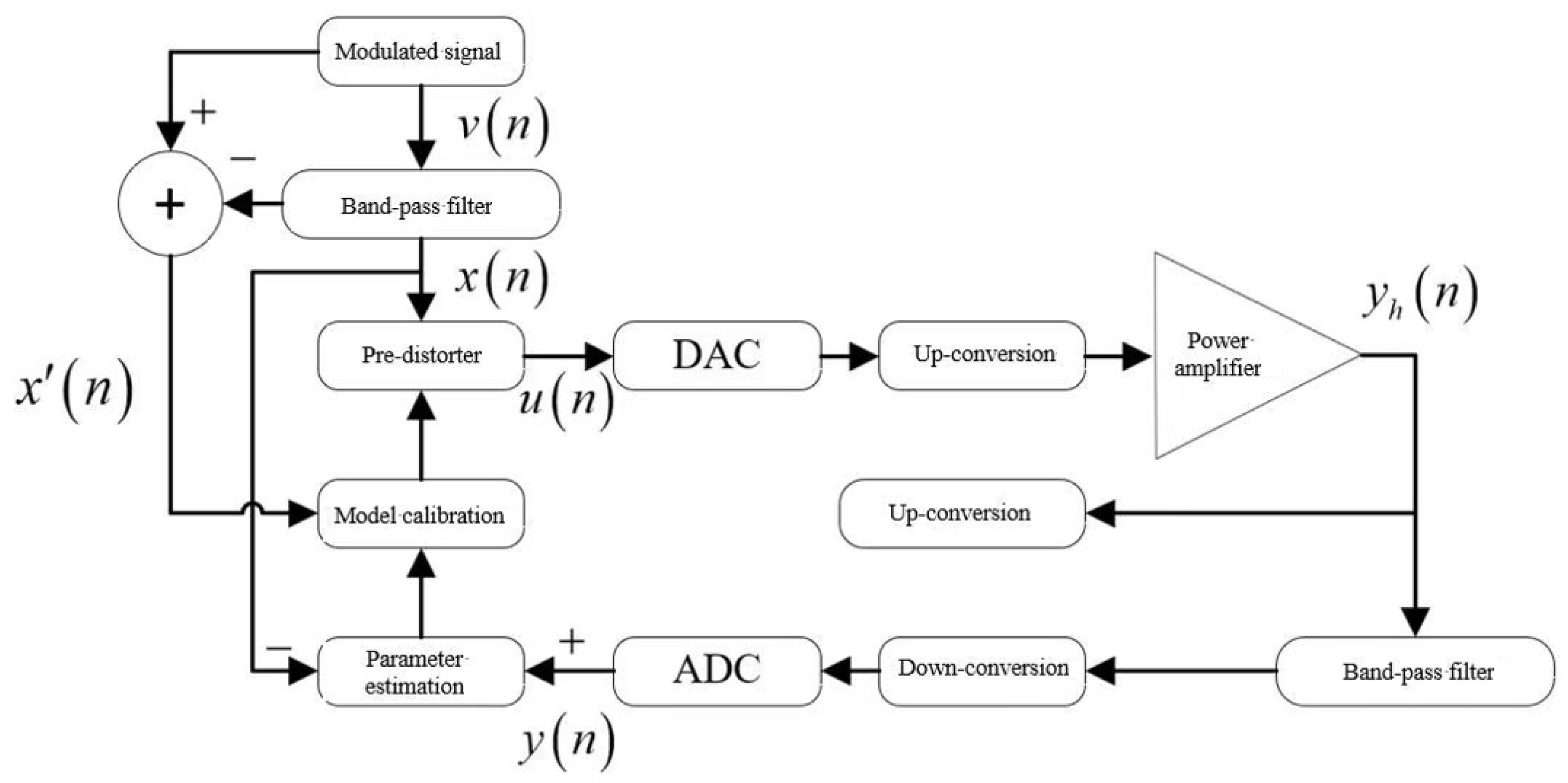
Figure 1 illustrates the wideband DPD architecture based on edge signal correction designed in this study. The model design is inspired by the direct learning method [14], which learns and corrects non-linear distortions directly from the differences between the input and output signals, thereby effectively reducing or eliminating distortions caused by the power amplifier.
The source signal v n passes through a bandpass filter to generate a band-limited input signal x n . The signal x n is then processed by a band-limited pre-distorter to produce the pre-distorted signal u n . The band-limited pre-distorter applies non-linear compensation to the input signal, thereby linearizing the in-band output of the power amplifier. The signal u n is converted into an analog pre-distortion signal via a Digital-to-Analog Converter (DAC). Before being sent to the power amplifier, it undergoes up-conversion to align with the amplifier’s center frequency. After passing through the power amplifier, the signal’s bandwidth becomes five times wider than that of the source signal [15]. Directly processing this wideband signal would significantly increase data rates and computational complexity. Therefore, a bandpass filter is employed to selectively capture feedback signals in the vicinity of the center frequency. The feedback signal is first down-converted and then digitized through an Analog-to-Digital Converter (ADC) to obtain an estimated input signal y n . The difference between the estimated input signal y n and the band-limited input signal x n is calculated. This difference is then processed through parameter calculations to determine the parameters of the pre-distortion model. To enhance the accuracy of the pre-distortion model, edge frequency signals x n are collected and fed into a parameter calibrator to compute the model’s cross-term parameters, thereby finalizing the calibration of the pre-distortion model. From the acquisition of the pre-distortion model parameters, through parameter calibration, a wideband digital pre-distortion model is ultimately generated, marking the completion of one iteration. Through multiple iterative updates, the inverse model of the power amplifier’s non-linear effects is progressively approximated, which compensates for non-linear distortions and thereby improves the quality and stability of communication transmission.

2.2. Wideband DPD Algorithm Based on Edge Signal Correction

In the direct learning method of DPD, establishing an accurate model of the power amplifier is essential for characterizing the relationship between its non-linear behavior and the input signal. This paper examines this relationship using a fully sampled analysis approach, which operates under the assumption that the system’s bandwidth matches the sampling rate. Additionally, memory effects that the power amplifier’s past states influence its current output must be considered. Consequently, precise modeling of RF PAs under fully sampled conditions is required.
Generally, RF PAs with memory effects can be described by various models that accurately capture the dynamic characteristics of the amplifier under different operating conditions. Selecting an appropriate model is crucial, as it directly affects the accuracy and effectiveness of the pre-distorter design. Under full sampling conditions, any DPD model with memory capabilities can be applied to ensure that the non-linearity and memory effects of the amplifier are fully compensated during signal processing. Therefore, a memory polynomial is adopted as the basic model, as shown in Equation (1):
y h l = k = 0 K 1 m = 0 M a k , m u h l m u h l m k
In Equation (1), ak,m represents the pre-distortion model matrix parameters, where k denotes the order of the pre-distortion model, and m denotes the memory depth of the pre-distortion model. The output y n can be expressed as follows:
y n = y h n F 2 = k = 0 K 1 m = 0 M a k , m u h n F 2 m u h n F 2 m k
In Equation (2), F 2 represents the sampling factor of the DAC and ADC. Since there is a relationship where u h n F 2 = u n , the relationship between u n and y n can be expressed as follows:
y n = k = 0 K 1 m = 0 M a k , m u n m F 2 u n m F 2 k
Assuming q = m F 2 , Equation (3) can be expressed as follows:
y n = k = 0 K 1 q = 0 M F 2 a k , q F 2 u n q u n q k
Let Q = M F 2 , then Equation (4) can be revised to the following:
y n = k = 0 K 1 q = 0 Q c k , q u n q u n q k
In Equation (5), ck,q represents the model parameters, where k denotes the non-linear order of the model and q denotes the memory depth of the model.
Equation (5) reveals the significant relationship between memory depth and sampling factors when constructing band-limited RF PA models and their corresponding DPD models. Since the band-limited characteristics of these models are closely related to the sampling rate, time-domain alignment techniques can be employed to model RF PAs and DPDs accurately. The key to this technique lies in ensuring consistency between the band-limited characteristics of the models and the sampling rate, thereby allowing the accurate capture of the signal’s time-domain characteristics during modeling. By finely adjusting the memory depth and sampling factors, the performance of the models can be optimized to ensure the accuracy and efficiency of pre-distortion processing. Additionally, this method helps reduce the common computational burden in wideband signal processing by operating directly within the useful frequency band, thereby eliminating unnecessary high sampling rate processing.
Next, the Least Squares (LS) algorithm is used to estimate the model parameters. This process involves precisely adjusting the model parameters to ensure that the pre-distortion processing effectively compensates for the non-linear characteristics of the power amplifier, ensuring that the amplification of in-band signals approaches ideal linear characteristics.
The model described in Equation (5) can be represented in matrix form as follows:
Y ^ = Ψ C ^
Y ^ = y ^ n , y ^ n + 1 , , y ^ n + N 1 T
where Y ^ is the estimated output signal matrix at a low sampling rate, and Ψ represents an N × K Q + 1 basis function matrix, where each row contains only the non-linear basis functions from Equation (5). Using the least squares method, the band-limited power amplifier model parameters C ^ are expressed as follows:
C ^ = Ψ H Ψ 1 Ψ H Y
Combining the obtained DPD model parameters C ^ with the input signal u n , the output signal y ^ n can be estimated.
To improve the model’s accuracy, this paper further explores the estimation process of the DPD model. It was found that the difference between the source signal and the actual amplified signal of the RF PA can directly quantify the deviation between the actual amplified signal and the ideal amplified signal. Processing this difference signal can effectively enhance the estimation accuracy of the model. By accurately calculating this error metric, the effectiveness of the pre-distortion technique can be evaluated. In this case, the DPD model can be adjusted and improved to ensure that the final amplification performance is closer to the desired linearity. This method effectively enhances the calibration capability of the DPD system, reduces signal distortion, and thereby improves the overall system performance. Additionally, this error-feedback-based iterative optimization process provides a systematic means for fine-tuning the DPD model, allowing the model to better adapt to various signals and operating conditions.
The input signal matrix for the pre-distorter can be expressed as follows:
X = x n , x n + 1 , , x n + N 1 T
Thus, the system error function is the following:
e = Y ^ X = e ˜ + ε
e ˜ = Ω Δ W l
In Equations (10) and (11), e ˜ represents the model error function, Δ W l is the parameter iteration weight, and Ω represents the basis function matrix, which can be expressed as follows:
Ω = Ω 0 , 0 n Ω 1 , 0 n Ω K 1 , Q n Ω 0 , 0 n + 1 Ω 1 , 0 n + 1 Ω K 1 , Q n + 1 Ω 0 , 0 n + N 1 Ω 1 , 0 n + N 1 Ω K 1 , Q n + N 1
Ω k , q n = x n q x n q k
Furthermore, the cost function can be modified as follows:
J = ε 2 = e e ˜
From Equations (10) and (11), the parameter iteration weight Δ W l can be derived as follows:
Δ W l = Ω H Ω 1 Ω H Y ^ X
W l = W l - 1 μ Δ W l
where the step size factor μ satisfies μ 1 , and Ω H represents the conjugate transpose of Ω .
First, the basic parameters of the pre-distortion model are obtained using the above algorithm. Then, considering the influence of dynamic cross-terms, the model parameters are optimized. The corrected power amplifier output signal after modification can be expressed as follows:
y n = k = 0 K 1 q = 0 Q c k , q u n q u n q k + k = 1 K 1 b k u n q = 0 Q d q u n q k
In Equation (17), bk represents the non-linear polynomial parameters, and dq represents the envelope parameters, both of which are related to the cross-terms.
Cross-terms are incorporated to improve the model’s fitting accuracy by utilizing edge signal data and calculating the cross-term parameters through the construction of a cost function.
J b k i * = L = 1 N e L i t k * ( L ) = 0
In Equation (18), t k ( L ) represents the association expression for b k . The b k corresponding to the minimum value of t k ( L ) is designated as b k i + 1 . Here, b k i denotes the i-th iteration of b k , and e L i represents the signal difference at index L. ( ) * indicates the complex conjugate.
Taking the partial derivative of J with respect to dq results in the following:
d q i + 1 = d q i + μ h 0 ( F L H F L ) 1 F L H e L i
In Equation (19), step size factor μ 1 and h 0 represents the gain parameter.
In summary, the goal of training the pre-distortion model is to iteratively optimize the pre-distortion processing parameters and cross-term parameters. This algorithm focuses on the signal within the central frequency band, using only the filtered frequency domain information for DPD model parameter estimation. Additionally, by incorporating cross-terms into the model structure and continuously calibrating the entire model using edge signals, the fitting accuracy of the model is significantly enhanced. The design of this algorithm reduces computational resource consumption while maintaining pre-distortion effectiveness, thereby providing a more efficient signal processing solution for wideband wireless communication systems. This method is expected to achieve a better balance between performance and resource usage in practical applications. Simulations and experiments will provide empirical evidence to validate the feasibility and benefits of this theory in actual wireless communication environments.

3. Simulation Results and Analysis

This section presents a comprehensive simulation analysis of the proposed band-limited digital pre-distortion (DPD) algorithm incorporating edge signal correction, with a focus on evaluating linearization performance through Error Vector Magnitude (EVM) metrics. The study systematically compares the algorithm against four established band-limited DPD implementations: an uncompensated system, the Band-Limited DPD (BLDPD) from reference [13], Down-Sampling DPD (DSDPD) from reference [2], and the conventional Memory Polynomial DPD (MPDPD) architecture. The experimental framework employs 5G NR-compliant 256QAM modulated signals with 100 MHz bandwidth, while the power amplifier (PA) emulation utilizes a Doherty configuration to replicate realistic non-linear characteristics and memory effects.
Figure 2 illustrates the power spectral density (PSD) profiles of PA output signals across the five configurations. Detailed spectral analysis reveals that the proposed algorithm achieves a 15.6 dB reduction in secondary channel power within the 80–180 MHz frequency offset range compared to the non-pre-distorted system. When benchmarked against existing DPD solutions, the method demonstrates superior spectral containment with 6.3 dB, 4.1 dB, and 9.0 dB improvements over BLDPD, DSDPD, and MPDPD, respectively. This enhanced spectral leakage suppression originates from the edge correction mechanism, which dynamically adjusts signal transition regions through adaptive windowing techniques, effectively mitigating Gibbs phenomena caused by abrupt signal truncation.
Quantitative performance evaluation under identical linearization bandwidth constraints, as detailed in Table 1, confirms significant EVM improvements. The EVM of the proposed DPD is 0.512%, which is 59.4% lower than that of the baseline BLDPD solution (0.864%), and 40.7% higher than that of the DSDPD (1.112%). When contrasted with traditional MPDPD architectures (1.262%), the EVM enhancement reaches 59.4%, while the uncompensated system (3.281%) shows an 84.4% error reduction. These advancements stem from two key innovations: (1) The integration of cross-term parameters establishes a multi-dimensional feature space that enhances memory effect modeling accuracy, particularly for wideband signals. (2) The edge correction module uses non-linear phase compensation to maintain the integrity of the signal at the time boundary and reduce the spectral splatter in the power measurement of adjacent channels.
These findings substantiate the algorithm’s dual capability in spectral efficiency enhancement and signal fidelity preservation, offering a viable solution for emerging wideband communication systems where spectral containment and power efficiency are paramount. The technical approach provides valuable insights for addressing non-linear distortion challenges in millimeter-wave massive MIMO deployments and next-generation terahertz communication prototypes.

4. Experimental Validation and Analysis

4.1. Experimental Setup

This section further validates the feasibility of the proposed improved scheme through hardware experiments. The experimental block diagram is shown in Figure 3, and the physical setup is depicted in Figure 4. The system mainly consists of two 32-bit microcontrollers, one FPGA, two DAC modules, one ADC module, and a spectrum analyzer. As shown in Figure 4, the left 32-bit microcontroller modulates the data stream to generate an OFDM signal, which is considered the source signal. The middle 32-bit microcontroller acts as the pre-distorter, internally storing the proposed model algorithm with default parameters. Upon receiving the source signal, it applies the pre-distortion model to convert it into a pre-distorted signal, which is then converted to an analog signal via the DAC module. The FPGA acts as the power amplifier, receiving the pre-distorted signal and amplifying it before sending it through the DAC module to the spectrum analyzer. Subsequently, the spectrum analyzer captures the amplified signal and analyzes the frequency spectrum of the power amplifier’s output signal.
In the operational workflow, a 32-bit microcontroller first generates the source signal and transmits it to the pre-distorter via the RS-485 protocol. Upon receiving this signal, the pre-distorter down-samples the source signal and applies pre-distortion processing to the sampled signal, thereby producing the pre-distorted signal. Additionally, it retains the remaining band-edge sampled signals for model calibration. Subsequently, the FPGA performs power amplification with analog non-linear distortion on the pre-distorted signal, splitting the amplified signal into two paths: one path is sent back to the pre-distorter for analysis and calculation of pre-distortion model parameters, while the other path is transmitted to the spectrum analyzer to monitor the frequency spectrum of the amplified signal.

4.2. Experimental Parameter Setup

To evaluate the effectiveness of the algorithm in linearizing wideband signals, the detailed parameter settings of the experimental platform are listed in Table 2.

4.3. Experimental Results Analysis

Following the hardware experimental setup depicted in Figure 4, the experimental parameters were configured, and comparative experiments were conducted using the traditional Memory Polynomial DPD algorithm as a reference. The experimental results are recorded in Table 3, and the spectrum analyzer displays the power spectra of the band-limited signals, as shown in Figure 5.
Table 3 presents a comparison of the ACPR values of the power amplifier’s output signals at different frequency offsets for the two schemes:
The experimental results demonstrate that in the channel with a 2 MHz frequency offset from the center frequency, the proposed DPD algorithm achieved an average ACPR value of −50.9 dBm, an improvement of approximately 11.75 dBm compared to the traditional MPDPD algorithm. In the channel with a 4 MHz frequency offset from the center frequency, the proposed DPD algorithm achieved an average ACPR value of −52.1 dBm, an improvement of approximately 12.85 dBm over the traditional MPDPD algorithm.
Based on the experimental results, it can be concluded that the proposed algorithm can be implemented using low-cost, low-computational-power hardware. By precisely processing signals near the center frequency and performing intelligent calibration, the proposed wideband DPD algorithm based on edge signal correction effectively addresses excessive computational data and poor accuracy in traditional DPD algorithms. This algorithm not only enhances signal processing efficiency but also offers new insights and methodologies for the future development of wideband communication technologies.

5. Conclusions

This paper proposes a wideband DPD algorithm based on edge signal correction. By collecting signals from the central frequency band and utilizing only the filtered frequency domain information for estimating the DPD model parameters, the proposed algorithm reduces both data volume and processing complexity. Furthermore, by incorporating cross-terms into the model structure and continuously calibrating the entire model using band-edge sampled signals, the fitting accuracy of the model is significantly enhanced. The proposed algorithm was simulated and analyzed using MATLAB R2024a and compared with four typical wideband DPD algorithms. The simulation results demonstrate that the proposed scheme exhibits a significantly lower secondary channel power within the frequency offset range of 80 MHz to 180 MHz, demonstrating superior anti-interference performance.
The proposed algorithm has demonstrated significant advantages in mid-frequency wideband scenarios. However, to meet the demands of future communication systems (6G, satellite communications, etc.), several challenges must be addressed, including operation at higher frequency bands, lower power consumption, and multi-channel coordination. Future research could integrate machine learning, novel hardware architectures, and standardized testing to advance DPD technology toward intelligent and full-spectrum adaptive development.

Author Contributions

Formal analysis, Y.L., H.Z. and Z.G.; Writing—original draft, Y.L., H.Z. and Z.G. All authors have read and agreed to the published version of the manuscript.

Funding

Key Scientific Research Projects of Universities in Anhui Province (2023AH052798).

Data Availability Statement

Data are contained within the article.

Conflicts of Interest

The authors declare no conflict of interest.

References

  1. Liu, F.L.; Zhang, X.J.; Wang, J.S.; Chang, H.; Jiang, C.Y.; Yang, G.C.; Han, R.L. Progress in digital predistortion based on machine learning. Acta Microw. Sin. 2023, 39, 62–69. [Google Scholar]
  2. Cheng, M.M. Research on Downsampling Digital Predistortion Technology; University of Electronic Science and Technology of China: Chengdu, China, 2023. [Google Scholar]
  3. Minelli, L.; Forghieri, F.; Shao, T.; Shahpari, A.; Gaudino, R. TDECQ-Based Optimization of Nonlinear Digital Pre-Distorters for VCSEL-MMF Optical Links Using End-to-End Learning. J. Light. Technol. 2024, 42, 621–635. [Google Scholar] [CrossRef]
  4. Jiang, W.H.; Duan, Y.X.; Li, M.Y.; Jin, Y.; Xu, C.Z.; Li, L. A Digital Predistortion Technique Based on Dimension-Weighted Blind K-Nearest Neighbor Algorithm. J. Electron. Inf. Technol. 2023, 45, 446–454. [Google Scholar]
  5. Dai, Z.J.; Kong, S.M.; Li, M.Y.; Cai, T.T.; Jin, Y.; Xu, C.Z. Digital Predistortion Technique Based on Improved Sparse Least Squares Gemini Support Vector Regression. J. Electron. Inf. Technol. 2023, 45, 418–426. [Google Scholar]
  6. Beltagy, Y.; Mitran, P.; Boumaiza, S. Direct Learning Algorithm for Digital Predistortion Training Using Sub-Nyquist Intermediate Frequency Feedback Signal. IEEE Trans. Microw. Theory Tech. 2019, 67, 267–277. [Google Scholar] [CrossRef]
  7. Wang, H.Y.; Li, G.; Zhou, C.B.; Tao, W.; Liu, F.L.; Zhu, A.D. 1-bit Observation for Direct-Learning-Based Digital Predistortion of RF Power Amplifiers. IEEE Trans. Microw. Theory Tech. 2017, 65, 2465–2475. [Google Scholar] [CrossRef]
  8. Miao, X.; Wan, F.Y.; Wang, L.; Li, B.H. Digital Predistortion Processing Based on Parameter Selection. Telecommun. Technol. 2019, 59, 1464–1468. [Google Scholar]
  9. Yao, Y.F.; Zhang, X.Z.; Cai, F.K.; Li, X.Y. Joint Compensation of Digital Predistortion for Non-ideal Characteristics of Moderation and Demodulation. Telecommun. Technol. 2024, 120–125. [Google Scholar]
  10. Guo, K.K. Research on Low Sampling Rate Predistortion Method of Wideband Power Amplifier; Beijing University of Posts and Telecommunications: Beijing, China, 2022. [Google Scholar]
  11. Fu, Z.M. Research on Key Technologies of Downsampling Digital Predistortion; Guilin University of Electronic Technology: Guilin, China, 2023. [Google Scholar]
  12. Ma, Y.L.; Yamao, Y.; Akaiwa, Y.; Ishibashi, K. Wideband Digital Predistortion Using Spectral Extrapolation of Band-Limited Feedback Signal. IEEE Trans. Circuits Syst. Regul. Pap. 2014, 61, 2088–2097. [Google Scholar] [CrossRef]
  13. Han, K. Research on Band-Limited Digital Predistortion Technology for 100 Megahertz Signal Bandwidth Power Amplifier; Beijing University of Posts and Telecommunications: Beijing, China, 2022. [Google Scholar]
  14. Muškatirović-Zekić, T.; Nešković, N.; Budimir, D. Efficient Neural Network DPD Architecture for Hybrid Beamforming mMIMO. Electronics 2023, 12, 597. [Google Scholar] [CrossRef]
  15. Wang, J.C.; Su, R.N.; Lv, J.S.; Xu, G.M.; Liu, T.J. Signal Reconstruction Deep Residual Neural Network-Based Bandwidth Augmented Methods for DPD Linearization. IEEE Microw. Wirel. Technol. Lett. 2023, 33, 243–246. [Google Scholar] [CrossRef]
Figure 1. Wideband DPD architecture based on edge signal correction.
Electronics 14 02170 g001
Figure 2. Power spectral density comparison.
Electronics 14 02170 g002
Figure 3. Experimental design block diagram.
Electronics 14 02170 g003
Figure 4. Hardware wiring setup.
Electronics 14 02170 g004
Figure 5. Frequency spectrum at 300 MHz, MPDPD scheme and proposed DPD scheme.
Electronics 14 02170 g005
Table 1. EVM comparison under the same linearization bandwidth.
Algorithm UsedEVM (%)Improvement vs. Proposed DPD
No DPD3.28184.4%
MPDPD Model1.26259.4%
DSDPD Model [2]1.11254.0%
BLDPD Model [13]0.86440.7%
Proposed DPD0.512-
Table 2. Experimental parameter settings.
Parameter NameParameter Value
Source Signal TypeOFDM
Source Signal Bandwidth8 MHz
Source Signal Sampling Rate16 MSPS
Power Amplifier Center Frequency300 MHz
Model Non-linear Order and Memory DepthK = 5, M = 3
Table 3. Experimental results.
Frequency Offset (MHz)ACPR (dBm)
MPDPD Algorithm2−39.4~−38.9
4−40.2~−38.3
Proposed DPD Algorithm2−51.4~−50.4
4−52.9~−51.3
Disclaimer/Publisher’s Note: The statements, opinions and data contained in all publications are solely those of the individual author(s) and contributor(s) and not of MDPI and/or the editor(s). MDPI and/or the editor(s) disclaim responsibility for any injury to people or property resulting from any ideas, methods, instructions or products referred to in the content.

