Article

Adaptive Measurement of Space Target Separation Velocity Based on Monocular Vision

1
School of Optoelectronic Engineering, Xidian University, Xi’an 710071, China
2
Xi’an Institute of Optics and Precision Mechanics, Chinese Academy of Sciences, Xi’an 710119, China
3
Xi’an Key Laboratory of Spacecraft Optical Imaging and Measurement Technology, Xi’an 710119, China
4
University of Chinese Academy of Sciences, Beijing 100049, China
*
Author to whom correspondence should be addressed.
Electronics 2025, 14(11), 2137; https://doi.org/10.3390/electronics14112137 (registering DOI)
Submission received: 4 April 2025 / Revised: 8 May 2025 / Accepted: 22 May 2025 / Published: 24 May 2025
(This article belongs to the Special Issue 2D/3D Industrial Visual Inspection and Intelligent Image Processing)

Abstract

:
Spacecraft separation safety is the key characteristic of flight safety. Obtaining the velocity and distance curves of spacecraft and booster at the separation time is at the core of separation safety analysis. In order to solve the separation velocity measurement problem, this paper introduces the YOLOv8_n target detection algorithm and the circle fitting algorithm based on random sample consistency (RANSAC) to measure the separation velocity of space targets according to a space-based video obtained by a monocular camera installed on the spacecraft arrow-shaped body. Firstly, MobileNetV3 network is used to replace the backbone network of YOLOv8_n. Then, the circle fitting algorithm based on RANSAC is improved to improve the anti-interference performance and the adaptability to various light environments. Finally, by analyzing the imaging principle of the monocular camera and the results of circle feature detection, distance information is obtained, and then the measurement results of velocity are obtained. The experimental results based on a space-based video show that the YOLOv8_n target detection algorithm can detect the booster target quickly and accurately, and the improved circle fitting algorithm based on RANSAC can measure the separation speed in real time while maintaining the detection speed. The ground simulation results show that the error of this method is about 1.2%.

1. Introduction

The velocity measurement technology of space targets has important research significance in the field of aerospace. The measurement of a spacecraft separation speed can ensure the reliability and safety of the separation process [1]. When spacecrafts are separated in multiple levels, the accurate measurement of the separation speed is the key for judging whether the separation timing is reasonable. If the separation speed is too fast or too slow, it may lead to structural collision, loss of attitude control or even disintegration. If the upper level engine is not completely shut down or the separation speed is abnormal, collisions may occur between each level, resulting in mission failure. By monitoring the separation speed in real time, emergency measures (such as self-destruction instructions) can be triggered to prevent out-of-control spacecrafts from posing a threat to operators or civilian facilities. Separation velocity measurement can optimize spacecraft performance and flight trajectory, directly affecting the initial velocity and fuel utilization rate at subsequent levels. For example, the separation speed needs to be matched with the optimal working condition of the next-level engine to maximize the range or load capacity. Moreover, aerodynamic interference or thrust imbalance generated during the separation process may cause the spacecraft to roll or yaw, and accurate speed measurement is an important input for the adjustment of the attitude control system [2,3].
In recent years, with the continuous progress of technology, space target velocity measurement has made remarkable breakthroughs in accuracy, speed and intelligence [4]. At present, velocity measurement techniques in the space environment are divided into three categories: ultrasonic velocity measurement, radar-based velocity measurement, and vision-based velocity measurement [5,6,7]. According to the infrared radiation characteristics of hypersonic cruise vehicles in near space, Shi Anhua et al. [8] found that the measurement results are affected by the trajectory and flight time. These research results provide a basis for ultrasonic speed measurement; especially for hypersonic vehicle speed measurement, it is necessary to consider the influence of many factors to ensure the correctness of the results. In the field of UAVs, AV Poltavskiy et al. [9] studied the optimization of UAVs’ information and measurement systems, emphasizing the importance of advanced guidance systems to improve UAVs’ performance. This optimization is suitable for speed measurement systems based on ultrasound, and the accuracy and stability of speed measurement can be significantly improved by improving the design of the measurement system.
Radar is also widely used as an important tool in the velocity measurement technology of aircraft. Li Xuesong et al. [10] used Doppler velocity measurement bias mitigation methods, including high-light modeling methods, to analyze the Doppler frequency components that contribute to the echo waveform. This method estimates the parameters of the high-light model according to the characteristics of the transmitted signal and uses these parameters to reduce the velocity measurement deviation in the Doppler velocity measurement, so as to improve the accuracy of the velocity measurement. In addition, Wilhelm Paul et al. [7] introduced a mobile system that uses a wind lidar to measure wind speed, direction and altitude with high accuracy, which is suitable for the wind energy industry and the meteorological field and provides a new idea for the speed measurement of aircrafts in complex environments. In the technology of velocity and feature measurement of aircrafts, the vision-based velocity measurement method has been widely studied. Yu Zongying et al. [11] introduced an enhanced technique for the precise determination of concentric circle centers in projection systems, achieving high accuracy without requiring prior knowledge of the circles’ diameter. The effects of the inner and outer radius of the circles and the rotation angle of the concentric circles on the error of the center position of the circular projection were analyzed through a single-camera experiment. In addition, Jia Gaowei et al. [12] proposed a near-field frequency domain imaging algorithm, which is suitable for the diagnosis of electromagnetic scattering characteristics of aircrafts in the range of 0.6~35 GHz. This algorithm can effectively identify and analyze the electromagnetic characteristics of aircrafts and provide important auxiliary data for vision-based velocity measurement.
For velocity measurement based on monocular vision, the most important technology is based on obtaining information on distance variations based on image sequences. At present, research on this technology is relatively mature nationally and abroad. Aiming at driving safety on roads, Yu Chunhe et al. [13] used the YOLOv5 target detection algorithm and DeepSort algorithm to detect and track the preceding vehicle and then a monocular visual measurement method to detect the distance and speed of the preceding vehicle in real time, thus solving the driving safety problem. Lei Zheng et al. [14] proposed a monocular visual distance measurement method based on the width of the target detection object and the distance between the target detection object and the ground contact point and a distance measurement model based on the principles of camera imaging model and coordinate system transformation. Aiming at the distance information analysis of a single image, Xu Zonghuang et al. [15] calculated the camera parameter matrix based on the double vanishing point method of the RANSAC algorithm, solved the coordinates of the midpoint in the image in three-dimensional space and finally obtained information on the distance. In order to meet the requirements of various space operations such as rendezvous, docking and acquisition, Qi Liu et al. [16] realized the position and attitude measurement of ultra-close spacecrafts. A stereo vision solution based on object detection and adaptive circle extraction was introduced to solve the pose measurement challenge under ultra-close low-light conditions. He Lixin et al. [17] analyzed and compared various analysis methods of single and binocular vision images and proposed a simple method to obtain information about the absolute depth of an object in the image measured by a monocular camera without adjusting the camera parameters.
For the application of monocular vision in aerospace, Guo Yijing et al. [18] proposed a method for analyzing the separation process of launch vehicles based on monocular visual images. The distance curve between the separation target and the camera device in a specific sequence was obtained by transforming and solving the motion parallax of the image sequence. Liu, Zibin et al. [19] proposed a method for estimating the pose of astronauts’ extravehicular activities based on monocular vision, making full use of the existing observational resources. The image sequence of the Shenzhou-13 astronauts during their extravehicular activities was used. Calibration was carried out using the spacesuit backpack or the circular handrail outside the space station, and attitude estimation was conducted using the feature points on the spacesuit. In order to achieve the real-time measurement of rocket height, Lu Rong et al. [20] studied the rocket recovery height measurement technology based on monocular vision and proposed an algorithm suitable for target feature extraction. Zhou Shutao et al. [21] studied the spatial coordinate reconstruction method based on monocular vision measurement technology. This method uses a camera to continuously take pictures of the components from different perspectives. By detecting the image coordinates of the encoded points, a matching relationship between adjacent frames is constructed, and then camera pose information is estimated based on the principle of relative positioning.
There is also a wide demand for space target velocity measurement based on monocular vision in the field of aerospace. For example, during and after the separation of the spacecraft and the booster, information on the relative distance between the spacecraft and the arrow-shaped body can be obtained through the image taken by the camera device installed on the spacecraft arrow-shaped body, and then the separation speed can be measured [22]. Information on the image after spacecraft separation includes circular targets. Regarding the circle detection algorithm, Jiang Lianyuan et al. [23] proposed a fast and accurate random circle detection algorithm, aiming to improve the speed and accuracy of circle detection based on random sampling. This algorithm is mainly studied for four purposes: calculating the circle parameters, determining the candidate circles, searching for true circles and improving detection accuracy. Ou Yun et al. [24] introduced the idea of information compression, compressing circular information on the image into a small number of points and simultaneously removing some noise through sharpness estimation and directional filtering. Then, the average sampling algorithm with a time complexity of 0 (1) was adopted to obtain the circle parameters stored in the information points and obtain the candidate circles. Finally, different constraint conditions were set for complete circles and defective circles based on the sampling results to find the true circle from the candidate circles.
Although image analysis technology has become a more mature technical field, there are various algorithms based on monocular vision and binocular vision pose measurement, and many technologies are applied in the space field. However, these excellent algorithms have not been fully utilized in spacecraft separation video analysis. Due to the urgency of this task, the designer needs to fully consider the fast transformation of the image results into the required data information. Based on the image processing technology in space field, this paper presents a monocular vision method for measuring the separation velocity of space objects. The method can easily and quickly calculate the relative distance between the object and the camera device on an image and further calculate the relative velocity.
In a nutshell, the major contributions of this paper are the following:
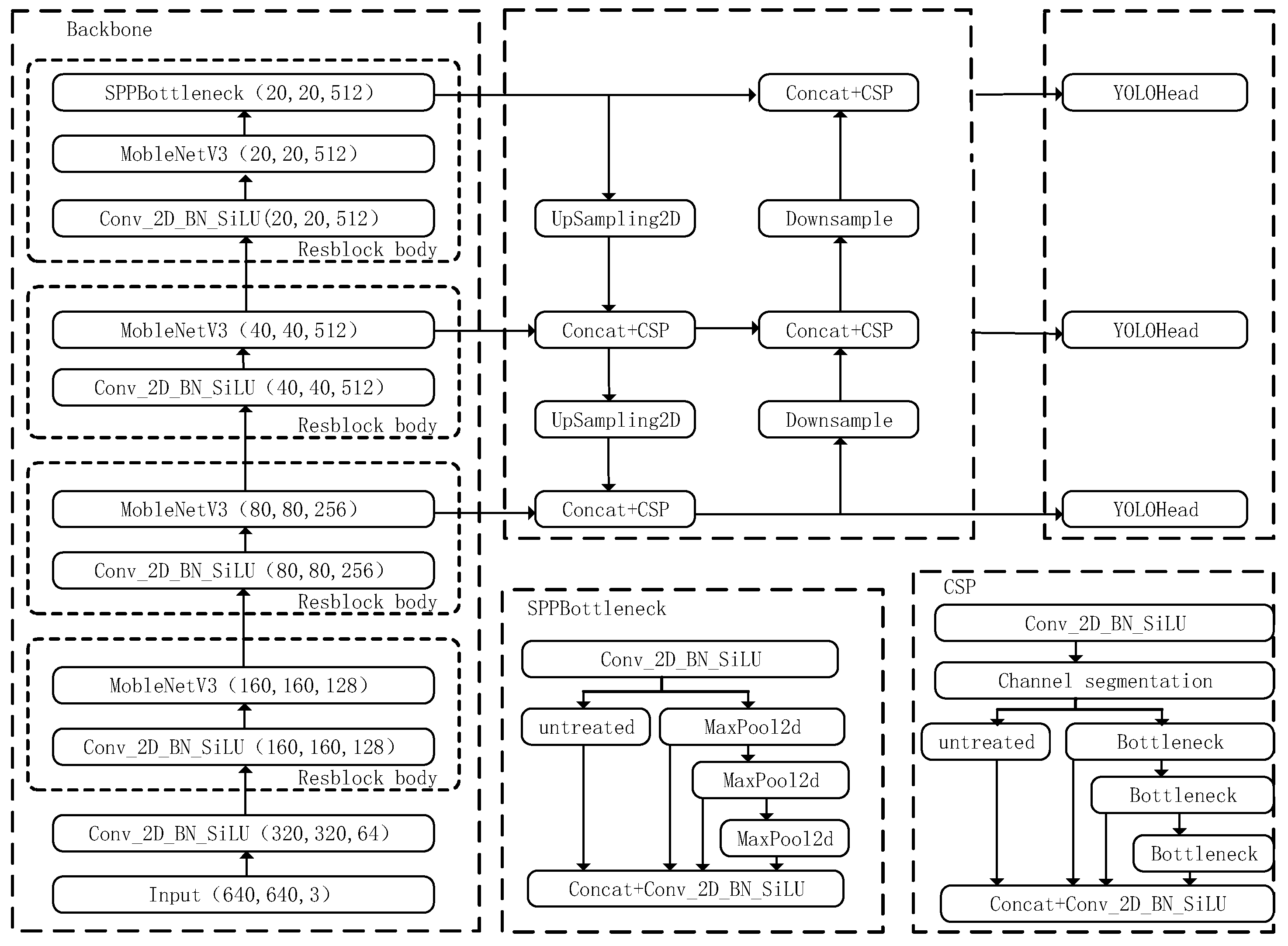
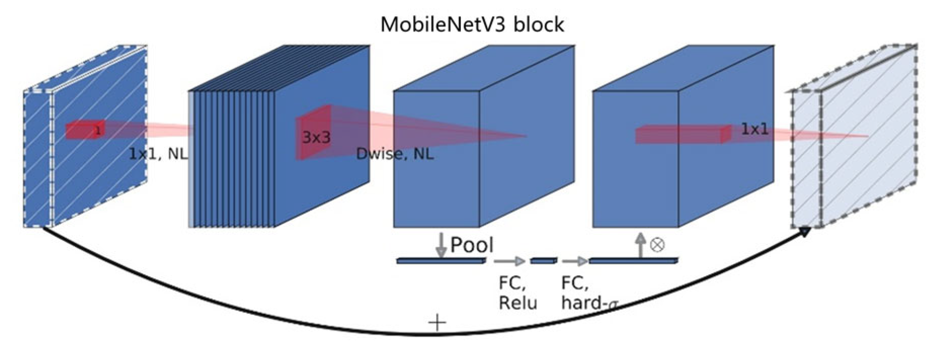
  • The MobileNetV3 network of MobileNet series is used to replace the backbone network of YOLOv8_n, which significantly reduces the number of model parameters and the amount of computation.
  • The circle fitting algorithm based on RANSAC is improved, and the anti-interference performance and adaptability to various light environments of target circle feature detection are improved.
  • The separation velocity is calculated based on monocular vision.
  • An experimental platform is built, and additional ground experiments are carried out to verify the correctness of the proposed algorithm.

2. Methods

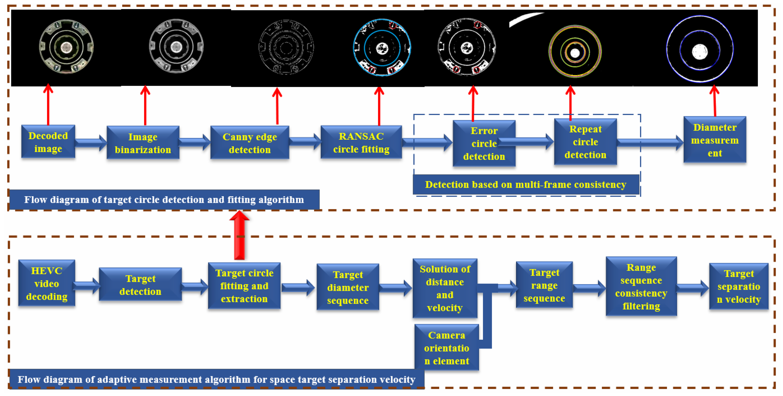
2.1. Algorithm Flow of Space Object Separation Velocity Measurement Based on Monocular Vision

As shown in Figure 1, the spatial target separation velocity measurement algorithm based on monocular vision includes the HEVC decoding of the spatial video at the separation moment; the target diameter sequence is obtained by target detection, circle detection, circle fitting and extraction, and the target distance sequence is calculated by the camera parameters. After consistency filtering, the target separation velocity is calculated. Target circle fitting and extraction allowed for carrying out binarization, Gauss low-pass filtering and Canny operator edge detection for each decoded image to obtain key information about the target circle. The circle detection algorithm based on RANSAC was used to detect circles in the processed images. Consistency detection based on multiple frames is proposed, and the diameter of the circle was finally detected.
A spatial video was obtained from the visible-light camera device installed on the spacecraft and was specifically used to record the separation process.

2.2. Target Detection

The YOLOv8 algorithm [25] is a next-generation algorithm model developed by Ultralytics after the YOLOv5 algorithm [26] and supports image classification, object detection and instance segmentation. Based on the scaling factor, different models of the N/S/M/L/X scale are provided to meet the needs of different scenarios. In the backbone network and neck component, the C3 structure of YOLOv5 was replaced by the C2f structure with more abundant gradient flow, and different channel numbers were adjusted for different scale models, greatly improving the model performance. The head component was replaced by the current mainstream decoupling head structure, separating the classification and detection heads and switching from anchor-based to anchor-free detection. In the calculation of loss, the positive sample allocation strategy of the Task-Aligned Assigner was adopted, and distribution focal loss was introduced. Considering the limited computing power of the camera device on the spacecraft arrow-shaped body, the YOLOv8_n object detection algorithm was used for circle target detection in this paper, and lightweight improvement was achieved. The improved structure is shown in Figure 2.
In this paper, MobileNetV3 [27] of the MobileNet series was used to replace the backbone network of YOLOv8_n. The MobileNet series network is a lightweight deep neural network proposed by Google for mobile phones and other embedded devices. Compared with traditional convolutional neural networks, MobileNet significantly reduces the number of model parameters and the amount of computation at the cost of slightly sacrificing accuracy. This achievement is possible thanks mainly to depthwise separable convolution, adopted by MobileNet. With this technique, traditional convolution is performed in two steps. First, the convolution operation is carried out for each input channel separately, and the feature graph is output. Then, the convolution operation is carried out for the feature graph of the convolutional output, and information is combined to adjust the number of output channels, thus greatly reducing the model complexity [28].
MobileNetV3 is based on the previous two versions of MobileNetV1 and MobileNetV2, introducing the SE (squeeze and excite) attention mechanism [29] module to make the model more focused on important features. At the same time, Hard-sigmoid and Hard-swish were designed as new activation functions to improve computational efficiency and model performance. MobileNetV3 has small and large versions. In this paper, MobilenetV3-small, which has lower computing power requirements, was selected. Its network structure is shown in Figure 3. Table 1 lists features such as input, operator, exp size and output of the YOLOv8_n structure of MobileNetV3.

2.3. Improvement of the Circle Fitting Algorithm Based on Random Sampling Consistency

2.3.1. Video Processing

Video processing began by extracting temporal segments containing the separation time through frame-by-frame analysis. Each frame underwent binarization to isolate the foreground regions, followed by Gaussian low-pass filtering to suppress noise while preserving structural details. Canny edge detection was then applied to extract high-contrast contours, ensuring that the retained edge information emphasized critical geometric features of the target circle for subsequent analysis.

2.3.2. RANSAC Circle Fitting Based on Multi-Frame Consistency Detection

The RANSAC circle detection algorithm [30] was applied to the pre-processed images to robustly estimate the target circle’s parameters (center coordinates and radius) from a mixture of edge data, including both meaningful circular contours and background noise. To address dynamic target motion and improve robustness, a multi-frame consistency mechanism was integrated (Figure 4). This approach employs a sliding window to track historical radius values across consecutive frames, enabling the algorithm to adapt to positional shifts while filtering transient outliers. By leveraging historical data, the radius search range is dynamically adjusted, reducing computational redundancy and enhancing accuracy in scenarios with gradual target movement. The iterative refinement process prioritizes inlier-rich models, ensuring stable convergence even under partial occlusions or low-contrast conditions. The main steps of the algorithm are as follows (Algorithm 1):
  • Preprocess the detected images and extract edges and establish a point set E composed of the coordinates of all edge points. Let the current cycle number be k = 0 . Initialize the inlier point set E _ i n l i e r s and the history radius storage queue R a d i u s _ h . Set the initial value of the range of radius r and the best model score B e s t _ S c o r e = 0 ;
  • Randomly extract 3 points from the boundary point set E , calculate the parameters of the circle determined by these 3 points [ a ,   b ,   r ] (center of the circle ( a ,   b ), radius r ). If the radius of the circle r is within the pre-set range, then continue to step 3; otherwise, move to step 7;
  • Calculate the distance d from each boundary point to the center of the circle obtained in step 2. If abs d r     ε ( ε is the acceptable inlier point deviation margin), the point is considered an inlier point, and its coordinates are stored in the inlier point set E _ i n l i e r s ; otherwise, it is regarded as an external point;
  • Calculate the number M for the inlier point set E _ i n l i e r s on the circle. If M is greater than the threshold M m i n , it is considered that the estimated circle model is reasonable enough, and these inlier points can also be regarded as valid points. In this case, continue to step 5.; otherwise move to step 7;
  • The parameter model of the circle is recalculated by the least-square method for all points in the point set E _ i n l i e r s ;
  • If   M is greater than the best score of the model, update the best fitting model; the best score of the model is updated to M ;
  • k = k + 1 ; if k > K m a x , return the best fit model parameters B e s t _ M o d e l and finish; otherwise return to step 2.
  • The circle radius parameters calculated by the current frame are stored in the radius storage queue of the history frame, and the threshold values of the radius range r m i n and r m a x are dynamically updated according to the mean plus or minus two times the standard deviation. At the same time, in order to ensure the rationality of the radius range (such as negative values), reasonable boundary values r _ m i n _ l i m t and r _ m a x _ l i m t need to be set.
Algorithm 1: Circle Fitting By Multi-Frame RANSAC
Initial & Input: Edge Points Set: E = e } = { e x i , e y i }
       Iterations: k = 0
        Inlinear Set: E i n l i e r s = n u l l
        B e s t _ S c o r e = 0
        B u f f e r _ S i z e = 5
        K m a x = Maximum iterations
        M m i n = Threshold of number of effective inlier points
        r m i n , r m a x = Allowable initial circle radius range
        ε = Acceptable distance error threshold
Output: B e s t _ M o d e l
H i s t o r y _ R a d i u s :   R a d i u s _ h ← Queue( m a x _ s i z e =   B u f f e r _ S i z e )
1.
while k < K m a x
2.
e 1 , e 2 , e 3 = R a n d o m { e }
3.
a , b , r = C i r c l e e 1 , e 2 , e 3       #Calculate ellipse parameters
4.
 if not ( r m i n     r     r m a x ) :         # Skip invalid circle
5.
   k + = 1
6.
  continue
7.
E i n l i e r s     { e     E   |   | d i s t a n c e ( e ,   ( a , b ) ) e |     ε }
8.
M = n u m ( E i n l i e r s )
9.
 if M > M m i n
10.
   a r e f i n e d , b r e f i n e d , r r e f i n e d = L e a s t S q u a r e s F i t ( E i n l i e r s )
11.
  if M > B e s t _ S c o r e :   #get the best parameters for historical fitting
12.
   B e s t _ M o d e l = [ a r e f i n e d , b r e f i n e d , r r e f i n e d ]
13.
   B e s t _ S c o r e = M
14.
k + = 1
15.
 end while
16.
 if R a d i u s _ h . s i z e ( ) > = B u f f e r _ S i z e :
17.
   R a d i u s _ h . p o p _ f r o n t ( )
18.
R a d i u s _ h . a p p e n d ( r r e f i n e d )
19.
r m i n = m a x ( r _ m i n _ l i m t , m e a n ( R a d i u s _ h ) 2 s t d ( R a d i u s _ h ) )
20.
r m a x = m i n ( r _ m a x _ l i m t , m e a n ( R a d i u s _ h ) + 2 s t d ( R a d i u s _ h ) )

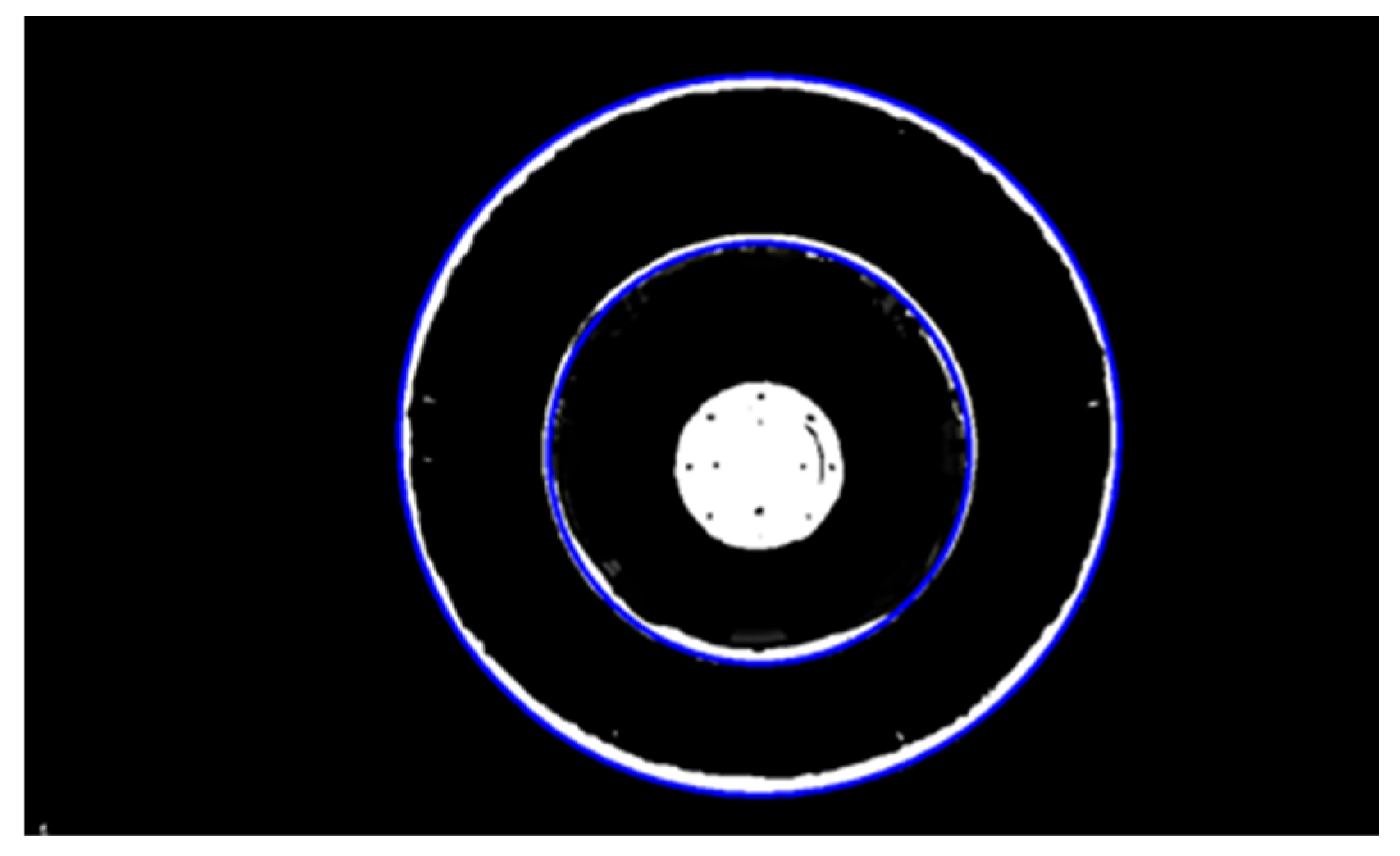
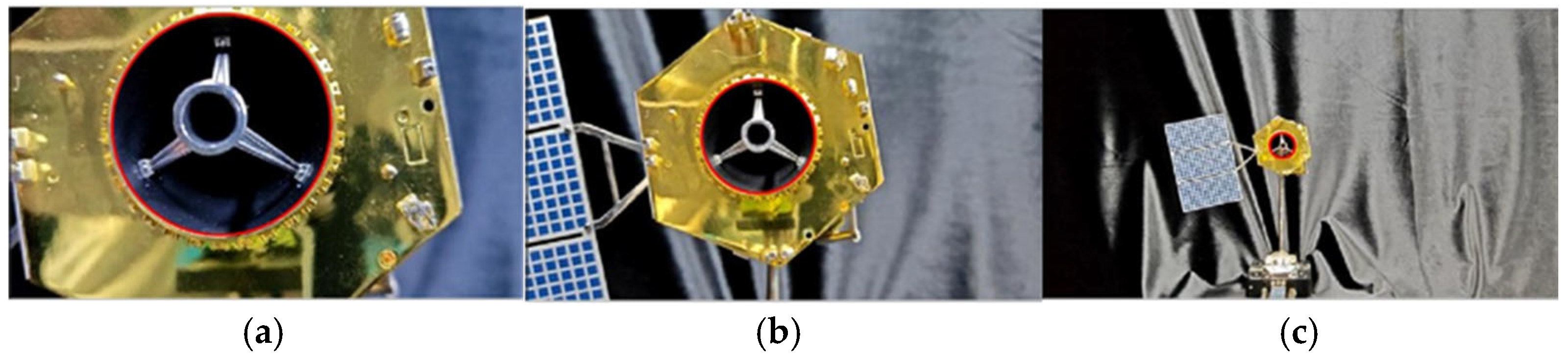
2.3.3. Extraction of the Target Circle

The target circle was selected considering the two contour circles marked in blue in Figure 4 that appeared as the longest in the video. The main idea of circle extraction is to derive the radius range of the two target circles according to the radius of the two target circles extracted the last time and then filter the radius of the two target circles from the radius results of circle identification.
However, the repeat detection scenario and error detection scenario in Figure 5 needed to be considered before filtering. For the error detection scenario in Figure 5a, the distance between the center coordinates of the circle to be detected and the average center coordinates of all detected circles was used as a basis for whether there was a misjudgment. For the repeated detection results for the same circle in Figure 5b, it was determined whether the absolute value of the difference between the radii of multiple circles in the radius set of all circles detected was less than a certain threshold. If it was less than that, it was determined to be the radius of the same circle.
Figure 4. RANSAC algorithm detection results (marked in blue).
Electronics 14 02137 g004

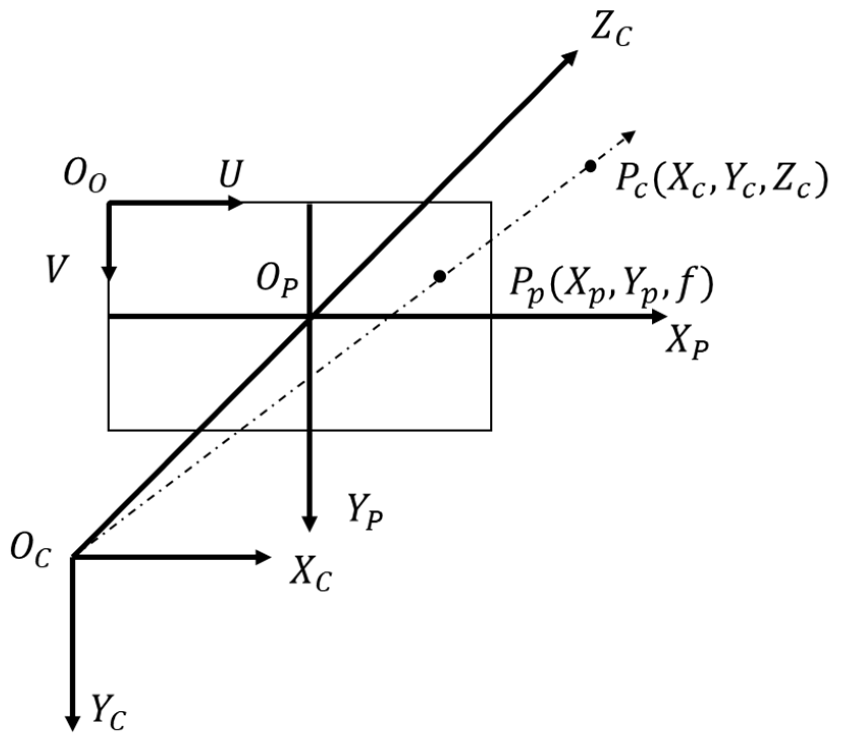
2.4. Separation Velocity Solution Based on Monocular Vision

2.4.1. Extraction of the Target Diameter

The simplest geometric representation model of the monocular vision imaging principle is a similar triangle, that is, the “pinhole imaging” model (see Figure 6). Suppose there is a point P in space; the position of point P in the world coordinate system is P w , the position in the camera coordinate system is P c , the position in the image coordinate system is P p , and the position in the pixel coordinate system is P : [31]
P w = [ X w , Y w , Z w ] T
P c = [ X c , Y c , Z c ] T
P p = [ X p , Y p , Z p ] T
P = [ u , v ]
The focal length of the camera f = Z p , according to the similar triangle, can be obtained as follows:
X c X p = Y c Y p = Z c f
When the camera takes a photo, the image on the imaging plane is scaled, translated and presented on the film, that is, on the pixel plane; so, there is also a scaling and translation relationship between the pixel coordinate system and the image coordinate system. In Figure 6, if the coordinates of the origin of the image coordinate system in the pixel coordinate system are [ C X , C Y ] T , then the coordinate values of P and P p present the following corresponding relationship:
u = X p d x + C X v = Y P d y + C Y
In this relationship, ( d x , d y ) are the physical length and width of the pixels, respectively. The following can be obtained from Formulas (1) and (2):
u = f X X c Z c + C X v = f Y Y c Z c + C Y
Here, ( f X , f Y ) represents the focal ratio of the camera, which is dimensionless. Expressing Equation (3) in the form of a matrix yields the following:
Z c = u v 1 f X 0 C X v f Y C Y 0 0 1 X c Y c Z c = K P c
where K is the internal parameter matrix of the camera. Suppose that the radius of the circle detected in the image coordinate system is r (in pixels) and the actual radius size of the circle is R . In the actual situation of our camera calibration, we approximately considered f X f Y = f . According to Formula (4), we deduced the following relationship:
d f = R r
where d represents the z-direction depth distance of the center of the spacecraft’s circular target in the camera coordinate system. The motion process of spacecraft separation can be approximately regarded as a linear motion of the separating section away from the optical axis of the camera. Therefore, within a certain period of time, the projection of the cross section of the spacecraft in the phase plane can always be regarded as a standard circle. At this point, we only needed to calibrate the camera to obtain its internal parameter matrix. With the actual radius of the spacecraft known, the Z-axis coordinates of the center of the circle in the camera coordinate system could be derived.

2.4.2. Solution of the Separation Velocity

For the interstage separation process, since the relative speed or relative distance of the two segments is usually concerned, it can be approximated that the end with the camera moves in a straight line up along the axis of the arrow-shaped body over a short distance, and the other end moves in a straight line down along the axis of the arrow-shaped body relative to the camera over a short distance. At this point, it can be approximately considered that the axis of the missile body coincides with the optical axis of the camera. The solution is based on the following idea: before separation, all parameters remain unchanged after the camera on the arrow-shaped body has shot the first image A; then, after the moving part has moved backward along the optical axis over a certain distance Δ d , the camera shoots the second picture B. Suppose that the object distance during the first imaging is u 1 and the radius of the circle on the image is r 1 ; the object distance during the second imaging is u 2 ( u 2 > u 1 ), and the radius on the image is r 2 . According to the similar triangle and Formula (5), we obtain the following:
Δ d = u 2 u 1 = ( r 1 r 2 ) r 2 u 1
where r is the radius of the circle target on the image, and Δ d is the changed distance of the center of the circle to the camera device between two frames. The separation speed can be calculated as follows:
v = d t
where t is the time difference between the two images.

3. Analysis of the Experimental Results

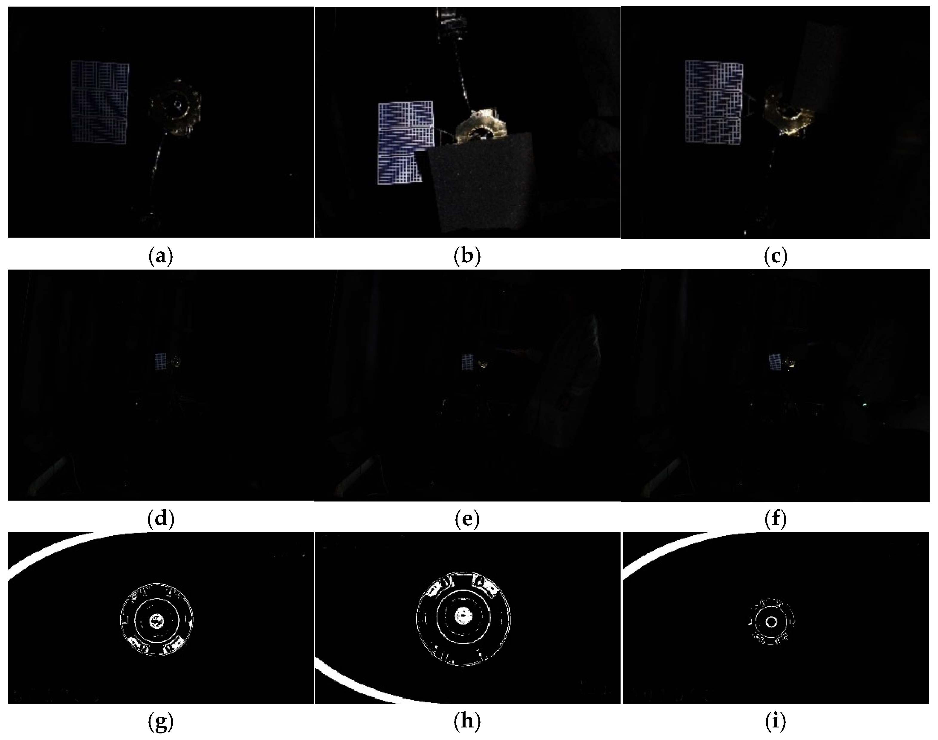
3.1. Experimental Results Based on Space-Based Video Verification of the YOLOV8_n Algorithm

In this paper, the model was trained and tested on a PC. The experimental environment was Windows 10 system, CUDA was 11.6, the display card was GeForce RTX3090 (NVIDIA Corporation, Santa Clara, CA, USA), and network opening frame was PyTorch 1.13.1. The operating language was Python 3.10, and the integrated development environment was Jupyter. The training rounds were set to 100, the batch size was set to 4, the initial learning rate was set to 0.01, and the optimizer was set to auto mode, that is, the model would automatically select the appropriate optimizer based on the set parameters. In total, 995 images of spacecraft separation were selected from the space-based video, and 2000 images were selected from the videos shot in the ground-built simulation environment as the experimental dataset. The separation targets were labeled and divided into a training set and a verification set according to the ratio of 9:1. Some of the pictures are shown in Figure 7.
In the experiment, the following four indexes were used to evaluate the algorithm: (1) floating-point operations (GFLOPs), a measure that reflects the computational complexity and represents the computing resource demand of the model; (2) average accuracy mean (mAP), which measures the overall detection performance of the model across all categories; (3) parameter quantity (Params), representing the number of trainable parameters in the model, which reflects the memory usage of the algorithm.
In order to verify the effectiveness of the improved module in the model, experiments were carried out, and the specific results are shown in Table 2. Firstly, YOLOv8_n was used as the baseline model for training verification. Then, with the fusion of the MobileNetV3 module, despite the 0.27% decrease in mAP, GFLOPs decreased significantly by 41.98% (from 8.1 to 4.8), and Params decreased significantly by 37.83% (from 3.1 to 1.7), indicating that MobileNetV3 performed well in reducing the computational load. The number of parameters was also greatly reduced.
In order to prove the advantages of the improved YOLOv8_n algorithm for target detection, experiments were carried out with YOLOv5_n, SSD-ResNet50, YOLOv7-tiny and YOLOX_nano on the experimental dataset. The experimental results are shown in Table 3.
Compared with YOLOv5_n, SSD-ResNet50, YOLOv7-tiny and YOLOX_nano, the improved YOLOv8_n showed significant enhancements in all aspects of network performance. The data in Table 2 show the values for each algorithm of measure performance and model complexity. In the comparison experiment, the GFLOPs and Params of the YOLOv5_n model were small, but the detection accuracy was only 0.9473. The SSDResNet50 model and YOLOv7-tiny model have high complexity and provided poor experimental results, indicating that these two models were not suitable for target detection in this work. Compared with the YOLOv8_n model and the first three models, the YOLOX_nano model showed great improvement in detection accuracy, but there is still room for improvement in the number of GFLOPs and Params. Combining all the above indicators, the improved YOLOv8_n not only achieved good performance in accuracy but also performed well in computational efficiency and model scale, proving its excellent performance in spacecraft separation detection.

3.2. Experimental Results Based on the Space-Based Video

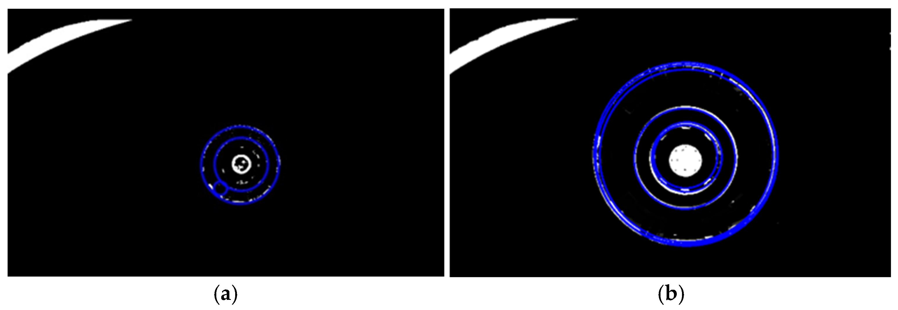
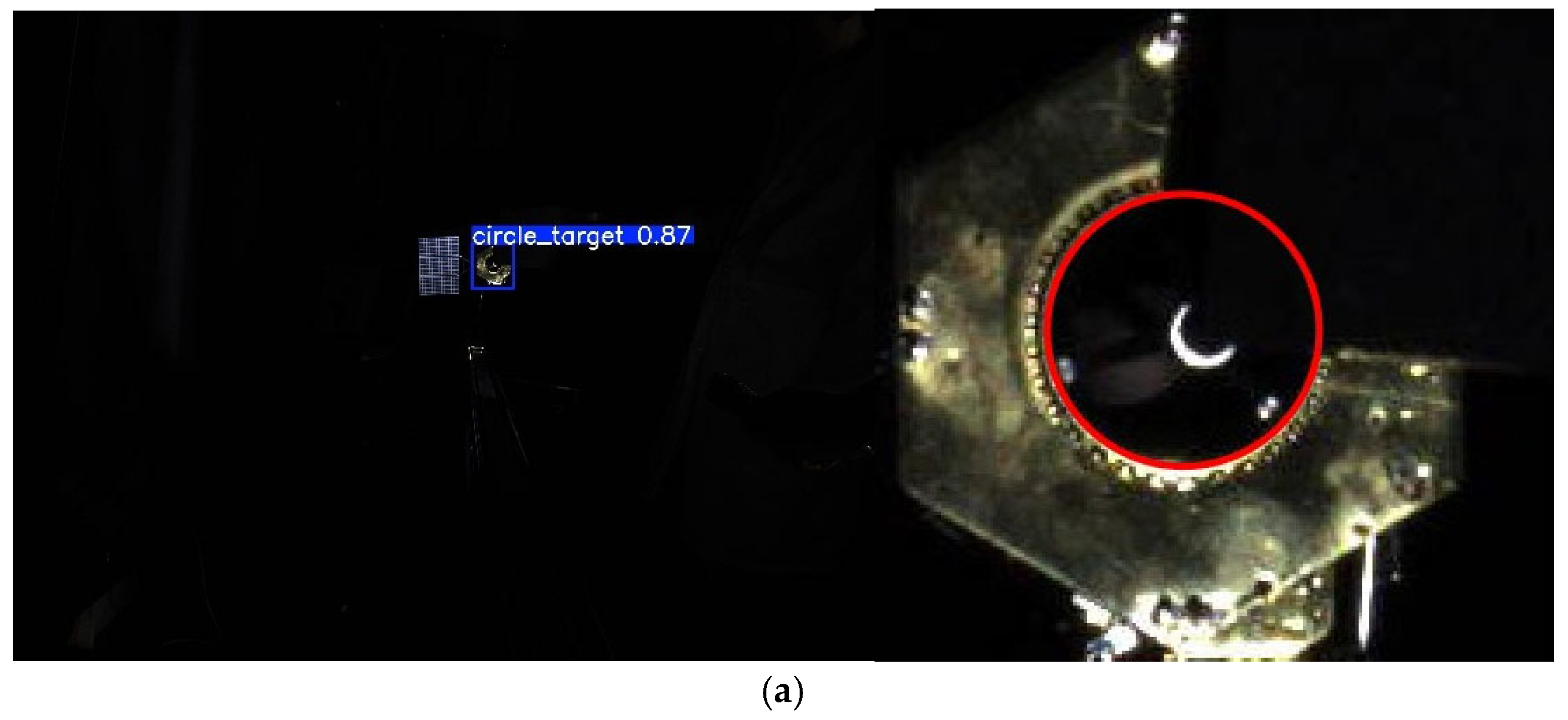
3.2.1. Verification of Circle Detection

The results of circle detection, which depended on the improved RANSAC algorithm, are shown in Figure 8. It can be seen in Figure 8 that the algorithm could correctly detect the circle target.

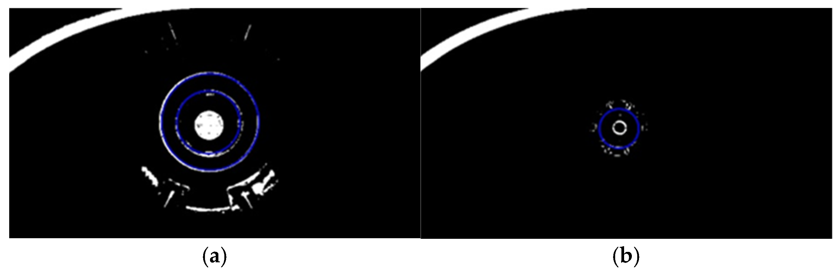
3.2.2. Verification of Circle Detection When Using the YOLOV8_n Algorithm

The purpose of introducing the YOLOv8_n target detection algorithm in this paper was to accelerate the speed of circle detection. The purpose was to use YOLOv8_n to detect separated spacecrafts and then the improved RANSAC algorithm to detect circles.
The calculation results are shown in Table 4. First, the average time of the diameter series was 1043 ms/FPS using the improved RANSAC. Secondly, the average time of detection of the spacecraft target was 42 ms/PFS using the improved YOLOv8_n. In addition, the average time of calculating the diameter sequence was 648 ms/FPS when using RANSAC, and the total average time was 690 m/s. The results show that the introduction of the target detection algorithm could reduce the time of calculating the diameter sequence.

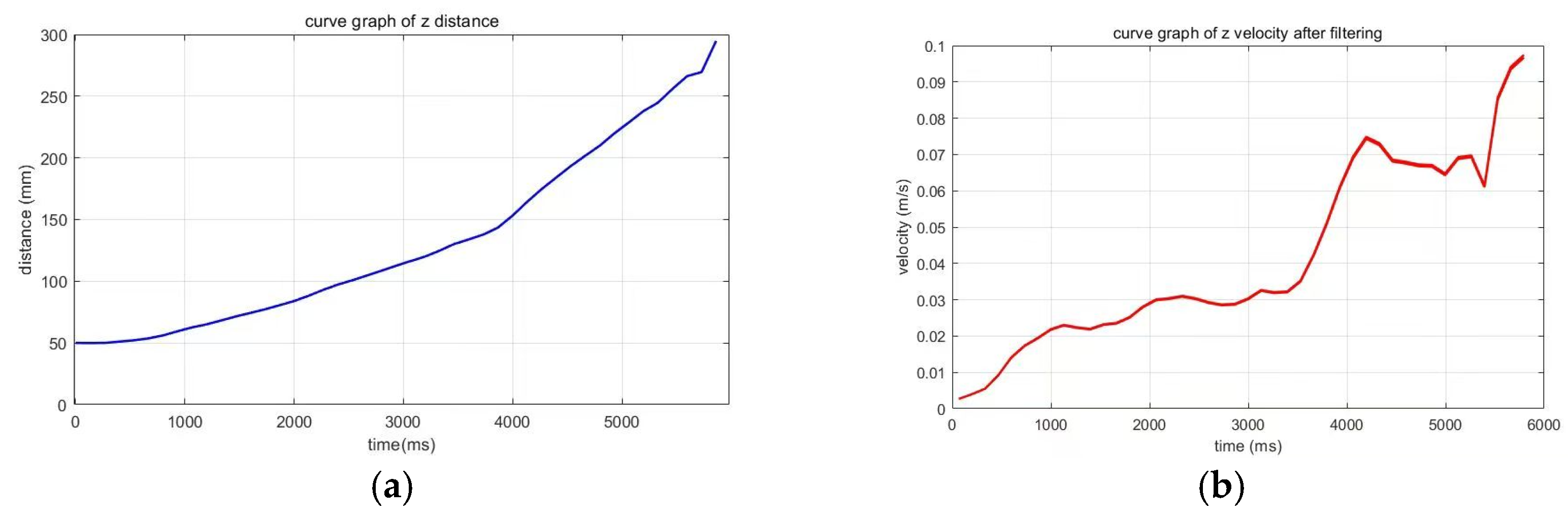
3.2.3. Results of the Velocity Measurement of the Space Target

Figure 9a reports the filtered distance change curve. Further, according to the filtered distance sequence, the obtained velocity change curve is shown in Figure 9b. The velocity change curve was verified by the spacecraft researchers, and the correctness of the calculation was finally proved.

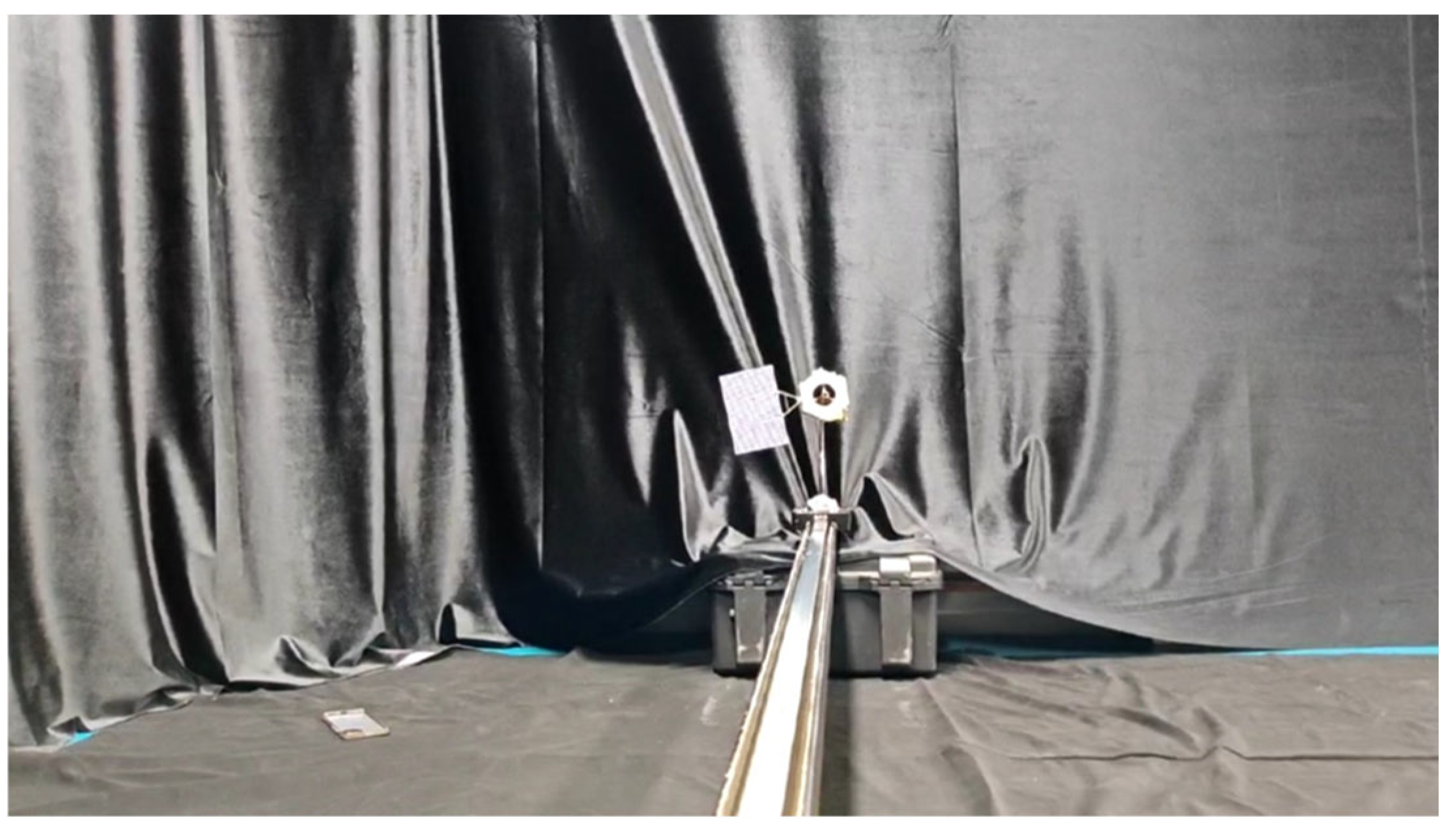
3.3. Experimental Results Based on Ground Verification

3.3.1. Experimental Environment

Due to the fact that the space target separation velocity measurement method based on the space-based video could not determine the actual target distance and velocity only according to the correctness of the spacecraft designer’s analysis results, this method is largely influenced by the human factor. In order to verify the effectiveness of the proposed algorithm, an experimental platform was built on the ground to simulate the separation scene between the spacecraft and the arrow-shaped body. The experimental platform is shown in Figure 10. In this scenario, the spacecraft arrow-shaped body was fixed, the camera device was installed on the booster, and the booster moved backwards. Circle detection and velocity measurement were verified.

3.3.2. Experimental Results

Figure 11a–c show the detection results at varying camera-to-target distances: 50 mm, 100 mm, and 250 mm. It can be seen from the figure that the algorithm could correctly identify the target circles. Figure 12a shows the distance change curve of the entire video screen, and Figure 12b shows the speed change curve.
Since the calculation of speed depends on time and distance information, the calculation result of the distance directly affects the accuracy of speed detection. Therefore, the comparison of seven groups of actual distance and measured distance results is shown in Table 5. Time information was obtained by the timing function inside the camera device, while the actual distance information was obtained by re-measuring the scene constructed on the experimental platform according to the picture. As shown in Table 1, the average error between the distance calculated by the algorithm in this paper and the actual distance was about 1.2%.
In order to improve the generalization of the proposed technology and verify the robustness of the algorithm, when constructing the dataset for our ground simulation experiments, we considered the imaging effects in different environments, such as variable lighting conditions, different degrees of occlusion, and appropriate adjustments to the angle of the target. Judging from the circle detection results in Figure 13, the algorithm presented in this paper has a certain generalization ability and can perform detection in complex environments.

4. Discussion

This paper introduced the YOLOv8_n target detection algorithm and the circle fitting algorithm based on random sample consistency (RANSAC) to measure the separation speed of space targets according to a space-based video obtained by a monocular camera installed on the spacecraft body. For the circle fitting algorithm, the number of iterations determines the number of times that the algorithm attempts random sampling. In each iteration, three points are randomly selected to calculate the parameters of the circle, and the quality of the model is evaluated based on the number of internal points. If the number of iterations is too small, it may not be possible to find a sample combination containing a sufficient number of inner points, which results in inaccurate model fitting (such as a large number of outliers). Too many iterations will increase the probability of finding the optimal model and reduce the possibility of missing the correct samples but will also lead to a significant increase in computing time, especially when the data set is large.
In the process of RANSAC fitting the circle, the threshold of the number of interior points is the criterion for judging whether the current model is good enough. When the circular model generated in a certain iteration satisfies the condition of “number of inner points ≥ the threshold”, this model is regarded as a candidate model and may be considered the best model. The acceptance of the threshold control model depends on the number of internal points that are covered. The higher the threshold is, the more the inner points that the model needs to cover in order to be accepted. The lower the threshold is, the more acceptable the model is (but may contain noise), resulting in the fitting results deviating from the real data.
The experimental results based on the space-based video showed that the YOLOv8_n target detection algorithm could detect the booster target quickly and accurately, and the improved circle fitting algorithm based on RANSAC could measure the separation speed in real time while maintaining the detection speed. Ground simulation experiments also proved the correctness of the algorithm proposed in this paper. However, the proposed method has certain limitations. For different spacecraft geometries or unexpected moving workpieces, the method proposed in this paper will fail. In future work, more appropriate goals should be chosen instead of merely focusing on achieving detection.
In addition, binocular vision and radar can be used for distance calculation. However, binocular vision requires two cameras, precise calibration is needed to avoid errors, and hardware complexity and cost are higher. Matching two images requires high computational complexity and relies on hardware acceleration. Lidar hardware is expensive and requires complex signal processing modules. Although the millimeter-wave radar has a relatively low cost, its resolution is limited, and the demand for radar computing resources is high. Monocular vision only requires a single camera, has low hardware cost and small size and is easy to integrate into resource-constrained devices. The depth can be estimated by combining the size of the object through a single-frame image, without the need for complex stereo matching. Traditional methods such as feature extraction and edge detection have low computational costs and are suitable for real-time processing. Modern deep learning models (such as lightweight CNN) can also run efficiently on cpus. Therefore, considering factors such as cost and computing resources, this paper selected the monocular vision method and combined it with a deep learning model (YOLOV8_n).

5. Conclusions

In order to solve the separation velocity measurement problem, this paper introduced the YOLOv8_n target detection algorithm and the circle fitting algorithm based on random sample consistency (RANSAC) to measure the separation velocity of space targets according to space-based videos obtained by a monocular camera installed on the spacecraft arrow-shaped body. The target detection algorithm was used to accelerate detection. Then, the circle fitting algorithm based on RANSAC was improved to improve the anti-interference performance and the adaptability to various light environments. By analyzing the imaging principle of the monocular camera and the results of circle feature detection, distance information was obtained, and then the measurement of velocity was achieved. However, in the future real-time separation velocity measurement of space targets, considering the result verification problem, more algorithms such as vision and radar should be combined.

Author Contributions

Conceptualization, D.L. and J.C.; methodology, H.Z., H.A. and Z.H.; validation, C.M. and H.Z.; data curation, Z.H.; project administration, H.Z.; funding acquisition, H.Z.; writing—original draft preparation, H.Z.; writing—review and editing, H.Z. and H.A. All authors have read and agreed to the published version of the manuscript.

Funding

This work was supported by the Natural Science Foundation of Shaanxi Province (2023-YBGY-234).

Data Availability Statement

The data presented in this study are available upon request from the corresponding author. The data are not publicly available due to privacy concerns.

Conflicts of Interest

The authors declare no conflicts of interest.

References

  1. Cao, F.; Xue, Y.; Miu, C.; Hao, H.; Qiao, Z.; Ding, N. Investigation on the Impact of Initial Velocity on Cold Separation Between the Missile and the Booster. Mod. Def. Technol. 2025, 53, 55–65. [Google Scholar]
  2. Shiquan, Z.; Zhengui, H.; Yongjie, G.; Qizhong, T.; Zhihua, C. Numerical Investigations on Wedge Control of Separation of a Spacecraft from an Aircraft. Def. Sci. J. 2018, 68, 583–588. [Google Scholar]
  3. Shuling, T.; Rongjie, L.; Ke, X. Investigation of Aeroelasticity Effect on Missile Separation from the Internal Bay. Int. J. Aerosp. Eng. 2023, 2023, 9875622. [Google Scholar] [CrossRef]
  4. Zhang, S.; Rao, P.; Zhang, H.; Chen, X. Velocity Estimation for Space Infrared Dim Targets Based on Multi-Satellite Observation and Robust Locally Weighted Regression. Remote Sens. 2023, 15, 2767. [Google Scholar] [CrossRef]
  5. Chen, M.Y.; Su, C.; Chang, Y.H.; Chu, Y. Identification and removal of aircraft clutter to improve wind velocity measurement made with Chung-Li VHF Radar. J. Atmos. Ocean. Technol. 2022, 39, 1217–1228. [Google Scholar] [CrossRef]
  6. Pellegrini, C.C.; Moreira, E.D.O.; Rodrigues, M.S. New analytical results on the study of aircraft performance with velocity dependent forces. Rev. Bras. Ensino Física 2022, 44, e20210410. [Google Scholar] [CrossRef]
  7. Wilhelm, P.; Eggert, M.; Oertel, S.; Hornig, J. Mobile system for wind velocity measurement. Tm-Tech. Mess. 2023, 90, 595–603. [Google Scholar] [CrossRef]
  8. Shi, A.; Li, H.; Shi, W. Infrared characteristics of Hypersonic cruise vehicles in Near Space. J. Ornol. 2022, 043, 796–803. [Google Scholar]
  9. Poltavskiy, A.V.; Tyugashev, A.A. Optimization of the Information and Measurement System of An Unmanned Aircraft. Reliab. Qual. Complex Syst. 2022, 4, 44–55. [Google Scholar] [CrossRef]
  10. Li, X.; Sun, D.; Cao, Z. Mitigation method of acoustic doppler velocity measurement bias. Ocean Eng. 2024, 306, 118082. [Google Scholar] [CrossRef]
  11. Yu, Z.; Shen, G.; Zhao, Z.; Wu, Z.; Liu, Y. An improved method of concentric circle positioning in visual measurement. Opt. Commun. 2023, 544, 129620. [Google Scholar] [CrossRef]
  12. Jia, G.; Yin, P.; Shao, S. Near-field frequency domain imaging algorithm for diagnosing electromagnetic scattering characteristics of aircraft. J. Natl. Univ. Def. Technol. 2024, 045, 10–19. [Google Scholar]
  13. Yu, C.; Zhang, L. Research on distance and speed measurement method of vehicle ahead based on deep learning. Comput. Inf. Technol. 2023, 31, 5–8+42. [Google Scholar] [CrossRef]
  14. Zheng, L.; Liu, L.; Lu, J.; Tian, J.; Cheng, Y.; Yin, W. Research on distance measurement of vehicles in front of campus patrol vehicles based on monocular vision. Pattern Anal. Appl. 2024, 27, 146. [Google Scholar] [CrossRef]
  15. Xu, Z.; Lin, Z.; Xu, M.; Huang, F. Single image distance information analysis model. J. Shenyang Univ. (Nat. Sci. Ed.) 2021, 33, 88–95. [Google Scholar] [CrossRef]
  16. Liu, Q.; Tang, X.; Huo, J. Attitude measurement of ultraclose-rangespacecraft based on improved YOLOv5s andadaptive Hough circle extraction. Appl. Opt. 2024, 63, 1364–1376. [Google Scholar] [CrossRef]
  17. He, L. Research on Depth Measurement of Monocular Visual Image. Ph.D. Thesis, University of Science and Technology of China, Hefei, China, 2018. [Google Scholar]
  18. Guo, Y.; Guo, G.; Jia, R.; Wang, Z.; Li, L. Separated Image Analysis Method based on Monocular Vision. Missiles Space Veh. 2022, 4, 130–133. [Google Scholar]
  19. Liu, Z.; Li, Y.; Wang, C.; Liu, L.; Guan, B.; Shang, Y.; Yu, Q. AstroPose: Astronaut pose estimation using a monocular camera during extravehicular activities. Sci. China-Technol. Sci. 2024, 67, 1933–1945. [Google Scholar] [CrossRef]
  20. Lu, R.; Zhang, G.; Cao, J.; Chen, W.; Guo, H.; Zhang, H.; Zhang, Z.; Mei, C.; Guan, L. Research on measurement technology of rocket recovery height based on monocular vision. Opt. Precis. Eng. 2024, 32, 2166–2188. [Google Scholar] [CrossRef]
  21. Zhou, S.; Li, L.; Zhang, W.; Ju, Y.; Zhang, Z.; Wang, T.; Su, Z.; Zhang, D. Position determination of strain gauges and applications based on videometrics. J. Exp. Mech. 2023, 38, 176–184. [Google Scholar]
  22. Wang, X.; Cui, W.; Li, J.; He, Y.; Li, H. A method to correct catalog orbit determination velocity. Mech. Eng. 2020, 42, 163–169. [Google Scholar]
  23. Jiang, L. A fast and accurate circle detection algorithm based on random sampling—ScienceDirect. Future Gener. Comput. Syst. 2021, 123, 245–256. [Google Scholar] [CrossRef]
  24. Ou, Y.; Deng, H.; Liu, Y.; Zhang, Z.; Ruan, X.; Xu, Q.; Peng, C. A Fast Circle Detection Algorithm Based on Information Compression. Sensors 2022, 22, 7267. [Google Scholar] [CrossRef] [PubMed]
  25. Jocher, G.; Qiu, J. YOLO by Ultralytics. DB/OL. 2023. Available online: https://github.com/ultralytics/ultralytics (accessed on 25 December 2024).
  26. Han, Y.; Liu, X.; Wang, X.; Wang, S.; Qi, P.; Dou, D.; Wang, Q.; Zhang, Q. Cloth Flaw Detection Method for Improving YOLOv5, Involves Obtaining Rgb Image of Cloth from the Data Set, Training Se-YOLOv5 Model, Importing Rgb Image Into Trained SEYOLOv5 Model for Defect Detection, and Outputting Detection Result. CN115700741-A, 7 February 2023. [Google Scholar]
  27. Ye, X.; Han, Z.; Zhou, Y.; Zuo, J.; Cheng, J.; Mu, C.; Chen, Q. Method for Diagnosing Fault of Photovoltaic Component Based on MobileNetV3, Involves Inputting Data To-Be-Detected to Target MobileNetV3 Network Model, and Outputting Different Diagnosis Result and Corresponding Frequency. CN117274680-A, 22 December 2023. [Google Scholar]
  28. Howard, A.; Sandler, M.; Chu, G.; Chen, L.-C.; Chen, B.; Tan, M.; Wang, W.; Zhu, Y.; Pang, R.; Vasudevan, V.; et al. Searching for MobileNetV3. arXiv 2019, arXiv:1905.02244. [Google Scholar] [CrossRef]
  29. Liu, C.; Li, J.; Li, X.; Kong, Y. Human Face Living Body Detection Method Combining Attention Mechanism and Residual Network Involves Using Trained Se-Resnet50 Network Model to Detect Face. CN114648815-A, 21 June 2022. [Google Scholar]
  30. Luo, Y.; Huang, W.; Wu, J.; Li, W. Ransac Algorithm Based Robust Machine Learning Meta-Algorithm Classifier Construction Method, Involves Determining Classifier Model with Samples as Final Selected Classifier Model, and Calculating Corresponding Classification Accuracy. CN108090512-A, 29 May 2018. [Google Scholar]
  31. Wang, Z. Method for Correcting Monocular Vision Scale in a Vehicle, Involves Determining Actual Value of Distance Between First Locating Point and Second Locating Point, and Correcting Scale of Monocular Vision Map Based on Proportional Relation. CN112102406-A, 18 December 2020. [Google Scholar]
Figure 1. Flow diagram of spatial object separation velocity measurement algorithm based on monocular vision.
Electronics 14 02137 g001
Figure 2. Improved YOLOv8_n network structure.
Electronics 14 02137 g002
Figure 3. Network structure of MobileNetV3-small.
Electronics 14 02137 g003
Figure 5. Two scenarios that needed to be processed: (a) error detection scenario, (b) repeat detection scenario.
Electronics 14 02137 g005
Figure 6. Schematic diagram of camera imaging.
Electronics 14 02137 g006
Figure 7. Some of the pictures in the dataset. (af) Images from the videos shot in the ground-built simulation environment, (gi) images from the space-based video.
Electronics 14 02137 g007
Figure 8. Results of circle detection: (a)result on large-size circle, (b) result on small-size circle.
Electronics 14 02137 g008
Figure 9. Results of velocity measurement of space target: (a) distance change curve, (b) velocity change curve.
Electronics 14 02137 g009
Figure 10. On the ground to simulate the separation between the spacecraft and the arrow-shaped body.
Electronics 14 02137 g010
Figure 11. Circle Detection Results at varying camera-to-target distances: (a) 50 mm distance; (b) 100 mm distance; (c) 250 mm distance.
Electronics 14 02137 g011
Figure 12. Results of velocity measurement of space target: (a) distance change curve; (b) velocity change curve.
Electronics 14 02137 g012
Figure 13. The results of object detection and circle detection under different conditions: (a) partial occlusion; (b) half occlusion; (c) no occlusion.
Electronics 14 02137 g013aElectronics 14 02137 g013b
Table 1. MobileNetV3-small in YOLOv8_n.
StageInputOperatorExp_SizeOutput
MobileNetV3 (160,160,128)160 × 160 × 128Conv1 + DWConv + SE + Conv2256160 × 160 × 128
MobileNetV3 (80,80,256)80 × 80 × 256Conv1 + DWConv + SE + Conv251280 × 80 × 256
MobileNetV3 (40,40,512)40 × 40 × 512Conv1 + DWConv + SE + Conv2102440 × 40 × 512
MobileNetV3 (20,20,512)20 × 20 × 512Conv1 + DWConv + SE + Conv2102420 × 20 × 512
Table 2. Effectiveness of our method on YOLOv8_n.
ModelmAP/%GFLOPsParams/M
YOLOv8_n99.138.13.1
YOLOv8_n+ MobileNetV398.864.81.7
Table 3. Comparison of the experimental results of different models.
ModelmAP/%GFLOPsParams/M
YOLOv5_n94.734.51.9
SSD-ResNet5092.653523.6
YOLOv7-tiny95.6313.26.2
YOLOX_nano97.481.71.9
YOLOv8_n99.138.13.1
YOLOv8_n+ MobileNetV398.864.81.7
Table 4. Comparison of detection time between improved RANSAC and improved YOLOv8_n + improved RANSAC.
NumberRANSACTime/FPS (ms)
1Improved RANSAC1043
2Improved YOLOv8_n + Improved RANSAC42 + 648
Table 5. Comparison of actual distance and measured distance results.
NumberTime (ms)Actual Distance (mm)Measured Distance (mm)Error (mm)Error (Error/Actual Distance) %
10505000
25005554+11.8
31000606000
420008082−22.5%
53000120118+21.67%
64000150153−32%
75000225226−10.4%
Disclaimer/Publisher’s Note: The statements, opinions and data contained in all publications are solely those of the individual author(s) and contributor(s) and not of MDPI and/or the editor(s). MDPI and/or the editor(s) disclaim responsibility for any injury to people or property resulting from any ideas, methods, instructions or products referred to in the content.

