Article

Synthetic-Aperture Passive Localization Utilizing Distributed Phased Moving-Antenna Arrays

1
Institute of Telecommunication and Navigation Satellite, China Academy of Space Technology, Beijing 100089, China
2
School of Aeronautics and Astronautics, Sichuan University, Chengdu 610017, China
3
Robotic Satellite Key Laboratory of Sichuan Province, Chengdu 610065, China
4
Multi-Source Information Intelligent Fusion Key Laboratory of Sichuan Province, Chengdu 610016, China
*
Author to whom correspondence should be addressed.
Electronics 2025, 14(11), 2114; https://doi.org/10.3390/electronics14112114
Submission received: 16 April 2025 / Revised: 7 May 2025 / Accepted: 14 May 2025 / Published: 22 May 2025
(This article belongs to the Special Issue Recent Advances and Applications of Radar Signal Processing)

Abstract

:
This article presents a Synthetic-Aperture Distributed Phased Array (SADPA) framework to address emitter localization challenges in dynamic environments. Building on Distributed Synthetic-Aperture Radar (DSAR) principles, SADPA integrates distributed phased arrays with motion-induced phase compensation, enabling coherent aperture synthesis beyond physical array limits. By analytically modeling and compensating nonlinear phase variations caused by platform motion, we resolve critical barriers to signal integration while extending synthetic apertures. An improved MUSIC algorithm jointly estimates emitter positions and phase distortions, overcoming parameter coupling inherent in moving systems. To quantify fundamental performance limits, the Cramer–Rao bound (CRB) is derived as a theoretical benchmark. Numerical simulations demonstrate the SADPA framework’s superior performance in multi-source resolution and positioning accuracy; it achieves 0.012 m resolution at 10 GHz for emitters spaced 0.01 m apart. The system maintains consistent coherent gain exceeding 30 dB across both the 1.5 GHz communication and 10 GHz radar bands. Monte Carlo simulations further reveal that the MUSIC-DPD algorithm within the SADPA framework attains minimum positioning error (RMSE), with experimental results closely approaching the theoretical CRB.

1. Introduction

Synthetic-Aperture Radar (SAR) utilizes moving platforms, such as aircraft and satellites, to achieve high directional resolution through aperture synthesis technology [1,2,3]. Building upon this framework, Distributed Synthetic-Aperture Radar (DSAR) systems deploy multiple coordinated transmitters and receivers, providing frequent revisit capabilities and all-weather operational performance [4,5,6]. Through centralized control of subarray apertures across cooperative satellites, DSAR enables coherent synthesis of electromagnetic waves over spatial domains. This results in detection capabilities comparable to those of large phased array radars with similar aperture products while providing benefits such as enhanced survivability, improved single-emitter positioning accuracy, and increased angular resolution for multi-target discrimination. Consequently, DSAR has become a pivotal area of research in modern radar development [6].
Building upon DSAR with the use of multiple satellites, distributed phased antenna arrays (DPAAs) offer significant advantages in emitter localization. By applying direct position determination (DPD) algorithms to the received emitter signals, DPAA radar outperforms traditional two-step localization methods such as time difference of arrival (TDOA) and frequency difference of arrival (FDOA), which first estimate parameters before determining the emitter’s position [7,8,9,10]. DPD algorithms exploit the position-dependent phase characteristics embedded in received signals through coherent processing of distributed array signals and spatial spectrum estimation [11,12,13]. This methodology enables super-resolution localization by effectively synthesizing large equivalent apertures. DPAA systems are conceptually similar to distributed phased radar receiving systems, a concept initially proposed by Lincoln Laboratory [14,15]. Distributed phased radar systems achieve full signal coherence at the receiving or transmitting antennas by estimating coherent parameters [16,17]. A receiving sub-array in these systems uses spectrum estimation algorithms to derive spatial information from the received signals [17]. Studies such as [18,19] have analyzed the accuracy gains of passive systems and MIMO radar for coherent positioning. Additionally, Refs. [20,21] described physical implementations of passive localization suitable for narrowband signals, whose accurate localization relies on spatial coherence. Crucially, modern coherent localization frameworks [22,23,24] integrate spatiotemporal signal features, with the Multiple Signal Classification (MUSIC) algorithm exhibiting particular efficacy for accuracy enhancement [25,26,27]. However, existing implementations predominantly target static deployment scenarios, lacking inherent compensation mechanisms for mobile antenna arrays.
To address the localization problem on moving platforms, various studies [28,29,30,31] have constructed models based on different information types and cost functions, achieving the localization of multiple signal sources using a single moving platform. However, these methods only utilize the received signals of each sampling pulse. In reality, virtual arrays can be synthesized through the motion of a single platform [32]. For instance, Ref. [33] confirms that motion synthesis of a single platform can improve localization accuracy in non-interference scenarios. While synthetic-aperture technology can enhance localization performance, its accuracy remains constrained when relying exclusively on platform motion. The concept of long-synthetic-aperture processing has been systematically investigated in passive positioning [34], where the received signal is continuously sampled in the fast time domain, and long synthesis of array output is conducted in the slow time domain during platform motion. This approach creates a long virtual aperture in the time dimension, achieving high azimuth resolution. Building upon this foundation, an enhanced dual-platform framework was proposed in [35]. Notably, Ref. [36] further developed an ultra-long-synthetic-aperture technique with two-stage Doppler spectrum broadening compensation for satellite-borne systems. Collectively, these advanced synthetic-aperture strategies have demonstrated sub-wavelength resolution capabilities. Despite these advances, existing studies such as [34,36] focus predominantly on single-platform configurations. Even the dual-platform approach in [35] essentially operates as a unified moving sub-array, failing to exploit distributed spatial diversity.
In this article, we propose a novel localization framework called Synthetic-Aperture Distributed Phased Array (SADPA), which combines the advantages of DPAA and synthetic-aperture passive arrays. To the best of our knowledge, there is very limited work published on SADPA for emitter localization. Our main contributions are highlighted as follows: (1) Proposing a novel localization framework: We introduce the SADPA framework, which builds upon DPAA and utilizes long synthesis techniques to further synthesize the aperture of moving arrays, thereby improving localization accuracy and resolution. (2) Multi-platform collaborative scanning: For distributed moving platforms, we adopt a multi-platform collaborative scanning method to ensure that all platforms can receive signals in the target area. To reduce communication and computing costs, we propose an intermittent signal transmission mode, which decreases data transmission volume while maximizing the spatial information of the moving arrays. (3) Compensating nonlinear phase variation: To address the problem of nonlinear phase variation in the steering vector during long synthesis, we establish a linear approximation factor to compensate for the Doppler diffusion effect caused by platform motion, forming a distributed equivalent virtual aperture. (4) Improved MUSIC-DPD algorithm: Building on MUSIC’s proven super-resolution capability and noise subspace robustness, we propose an improved MUSIC-DPD algorithm to jointly estimate the unknown emitter position parameters and compensate motion-induced phase variations directly from received signals. (5) Derivation of Cramer–Rao bound (CRB): We derive the corresponding CRB for SADPA emitter localization, providing theoretical limits on the localization accuracy.
The rest of this paper is organized as follows: Section 2 describes the signal model of SADPA systems and examines the advantages of the DPAA. Section 3 introduces the proposed MUSIC-DPD algorithm. Simulations and analysis of the proposed detectors are given in Section 4. Finally, conclusions are drawn in Section 5.
Notation: R n and C n denote the n-dimensional real and complex vector spaces, respectively. R m × n and C m × n denote the m × n -dimensional real and complex matrix spaces, respectively. ( · ) T , ( · ) * , ( · ) , tr ( · ) , vec ( · ) , and  λ max ( · ) denote the transpose, complex conjugate, conjugate transpose, trace, vectorization, and largest eigenvalue of a matrix or vector, respectively. | · | denotes the magnitude of a complex scalar. · 2 denotes the 2 norm of a vector. · F denotes the Frobenius norm of a matrix. ⊗ denotes the Kronecker product. Re ( · ) denotes the real part of a parameter, vector, or matrix. Finally, I n and 0 n denote the identity matrix and zero matrix with a size of n × n .

2. SADPA Framework and Signal Model

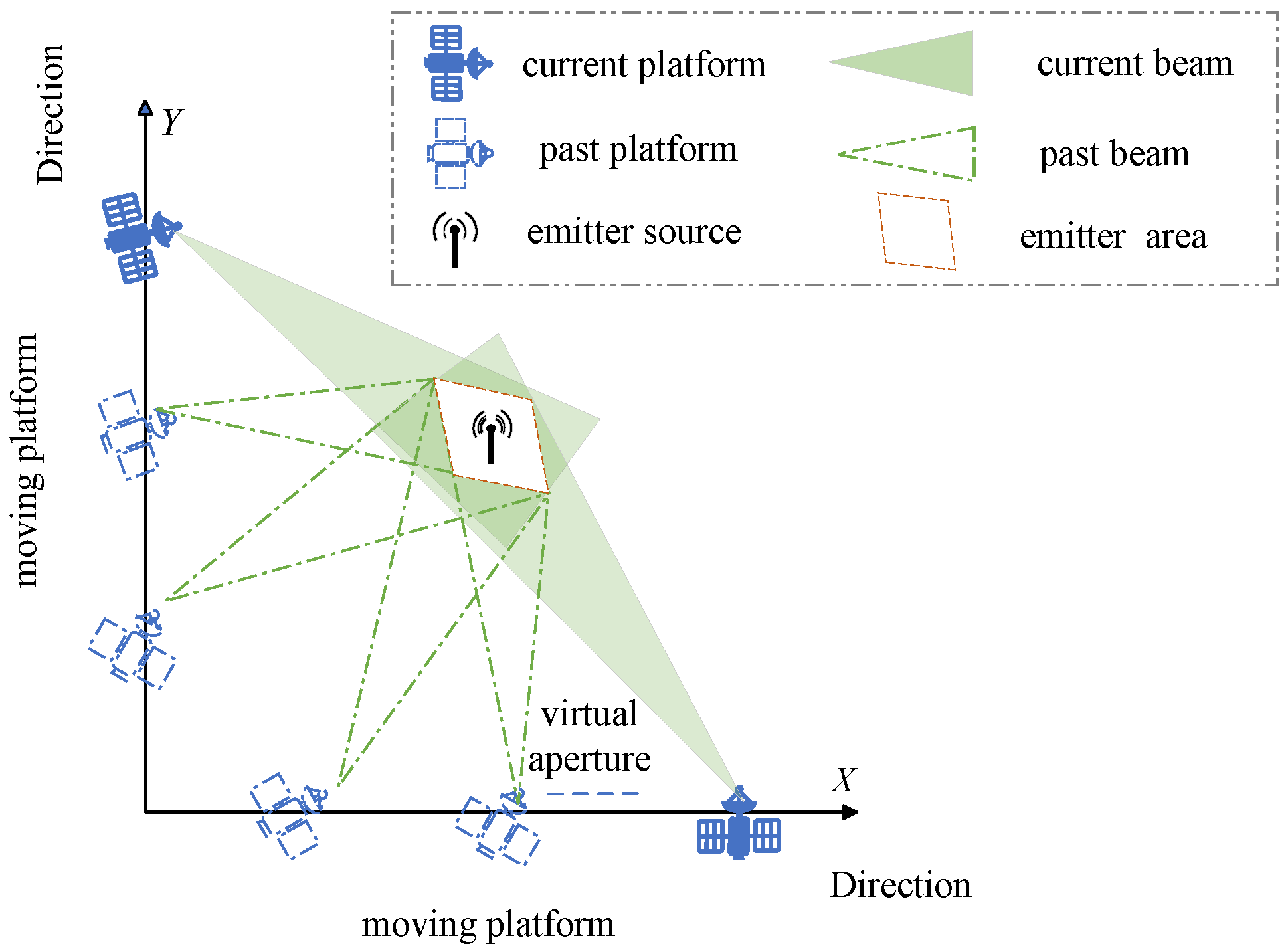
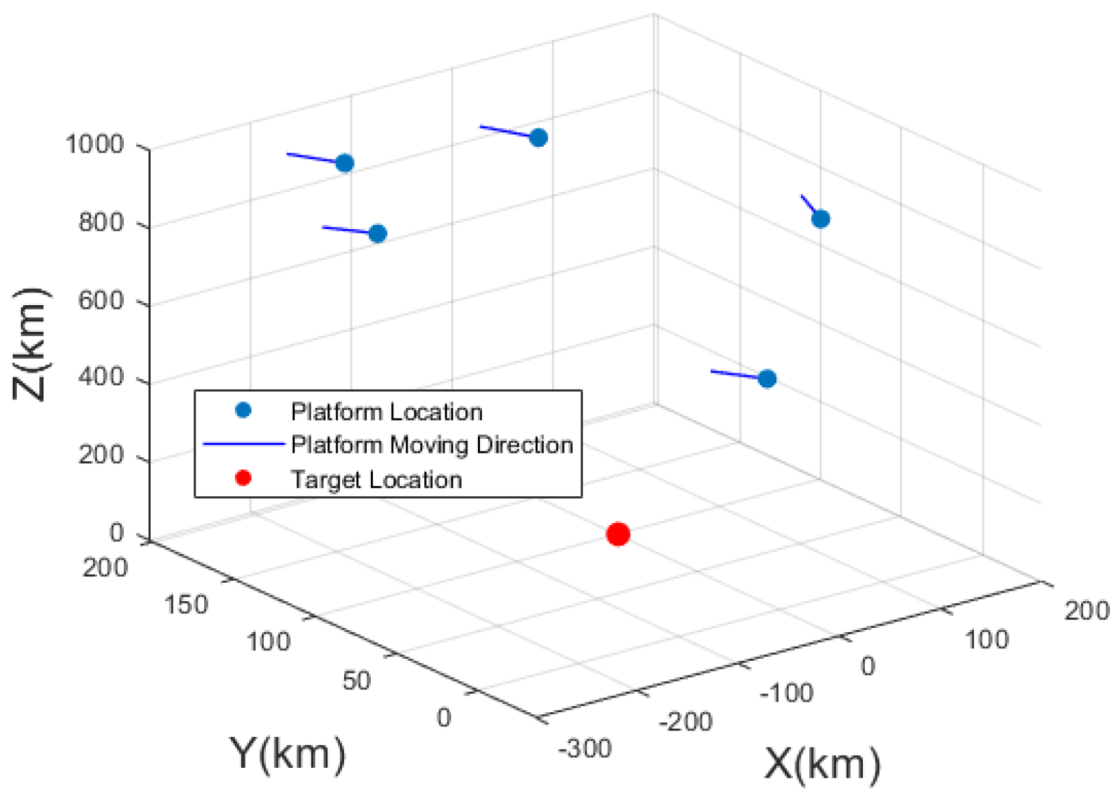
2.1. Localization Scenario

In this section, we describe the scenario for the SADPA, which encompasses collaborative scanning by distributed platforms and an intermittent signal transmission mode. We consider a distributed array composed of M platforms, where each platform is equipped with receiving antennas.
For simplification, we assume that all platforms are positioned at different fixed altitudes and are moving in straight paths at constant velocities. In practice, integrating the platform velocities or motion trajectories makes it possible to derive the compensation factor (15), achieving equivalent performance for curves and variable-speed motion. Furthermore, the geometric configurations of multi-satellite formations are inherently flexible in spatial distribution, enabling universal adaptability to arbitrary baseline arrangements. A stationary ground-based emitter with unknown coordinates ( X , Y , Z ) serves as the object of interest. The collaborative scanning mode of the mobile platforms is depicted in Figure 1. For instance, suppose that two platforms, flying along straight trajectories, collaboratively scan the target area. As they advance, the beam vectors of both platforms continuously point towards the emitter’s position, ensuring consistent signal reception from the emitter.
The signal acquisition and processing workflow is illustrated in Figure 2. Distributed platforms sample signals with duration T r in the fast time domain, followed by periodic sampling at intervals of the transmission period T. Each sampling instance captures l signal samples, with the complete localization process spanning K sampling periods. Consequently, K × l signal snapshots are acquired per emitter. All sampled data are transmitted within their respective T intervals. For radar systems, T corresponds to the pulse repetition interval (PRI) and T r to the pulse width. In contrast, communication signals exhibit T values in milliseconds and T r in microseconds, with continuous signals approximated as pulsed sequences. This hierarchical scheme provides three key advantages: (1) sufficient time T for reliable data transfer and concurrent processing of heterogeneous signals; (2) inherent compensation of propagation delays through pulsed phase alignment; and (3) computational efficiency, with only K transmissions required.
Furthermore, in DPAA systems, the continuous transmission mode necessitates phase shifts for all signal samples, whereas the intermittent transmission mode requires only an overall phase shift for each sampling period. This significantly reduces the computational burden associated with phase adjustments.

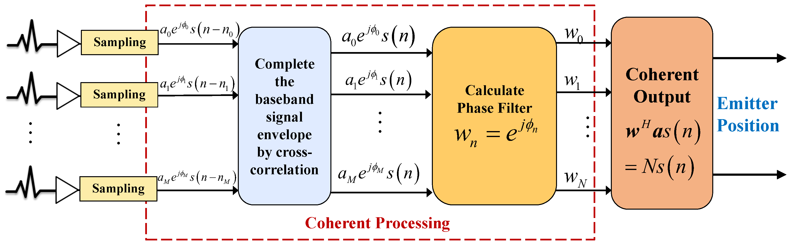
2.2. Signal Processing and Framework of DPAA System

With M elements, we assume the emitter signal is narrowband and that the received signal can be approximated as a single-frequency signal given a sufficiently high sampling rate. In this paper, we treat all M platforms as a distributed array, where each individual platform acts as a subarray. During the sampling period T r , we assume that the motion of the platforms can be neglected.
We assume the emitter signal for each subarray is x m ( n ) = a m e j ϕ m s n n m after sampling operation, where a m represents the amplitude of the signal received by the mth subarray, while  ϕ m denotes the phase shift caused by the difference in arrival time. The baseband signal envelope can be reconstructed using a cross-correlation algorithm, allowing us to time-align the signal as x m ( n ) = a m e j ϕ m s n , thus ignoring the baseband signal’s time delay. For the purpose of subsequent derivations, we assume that the received signal amplitudes of all subarrays remain equal, which does not impact the positioning accuracy.
We list all received signals as a vector, which can be expressed as
x ( n ) = x 1 n x 2 n x M n T = As ( n ) + n n
where A = a 1 ϕ 1 , φ 1 a 2 ϕ 2 , φ 2 T is the array steering matrix. a i ϕ i , φ i stands for the array steering vector for the ith source, with  ϕ i , φ i denoting the pitch and azimuth angles of the source i. n n represents Gaussian white noise. Consider all sampling data, the array output is given by
X = x t 1 x t 2 = AS + N
The distributed coherence of the target signal at the subarray receiver is accomplished by constructing a weight vector w to align the phases of each subarray, thereby improving positioning accuracy through SNR enhancement and multi-target resolution via baseline extension. Let y ( n ) = w H x ( n ) , and let the output be expressed as
w H R Y w = w H AS S H A H w + w H N N H w
where R Y = AS S H A H is the sample covariance matrix. With precise knowledge of the target source direction and the relative positions between subarrays, the receiving weight matrix W can be constructed, ensuring that W H A I , to achieve distributed receiving coherence. Thus, the output of coherent processing is given by w H a s ( n ) = N s ( n ) . Compared to non-coherent processing, the gain of DPAA signal processing is
Gain = w H AS S H A H w N σ s 2 = N
where non-coherent signals cannot be accumulated, and  σ s 2 represents the signal power. It is evident that the gain scales proportionally with the number of receivers in DPAA signal processing, as illustrated in Figure 3. Utilizing the MUSIC algorithm, the position of the emitter can be obtained according to [26]:
P ( φ , ϕ ) = 1 w k ( ϕ , φ ) H E n E n H w k ( ϕ , φ )
where E n is the noise subspace of the sample covariance matrix.
The localization resolution fundamentally scales with the effective baseline length in distributed systems. While single-platform synthetic-aperture techniques [33] rely solely on platform motion to create temporal baselines, the proposed DPAA architecture synthesizes a spatial baseline across multiple platforms through phase-coherent processing. This enables an equivalent baseline length proportional to the inter-platform distance, which is orders of magnitude larger than the motion-induced baseline of a single platform. Consequently, DPAA achieves proportionally higher resolution than single-platform approaches under a comparable observation duration.

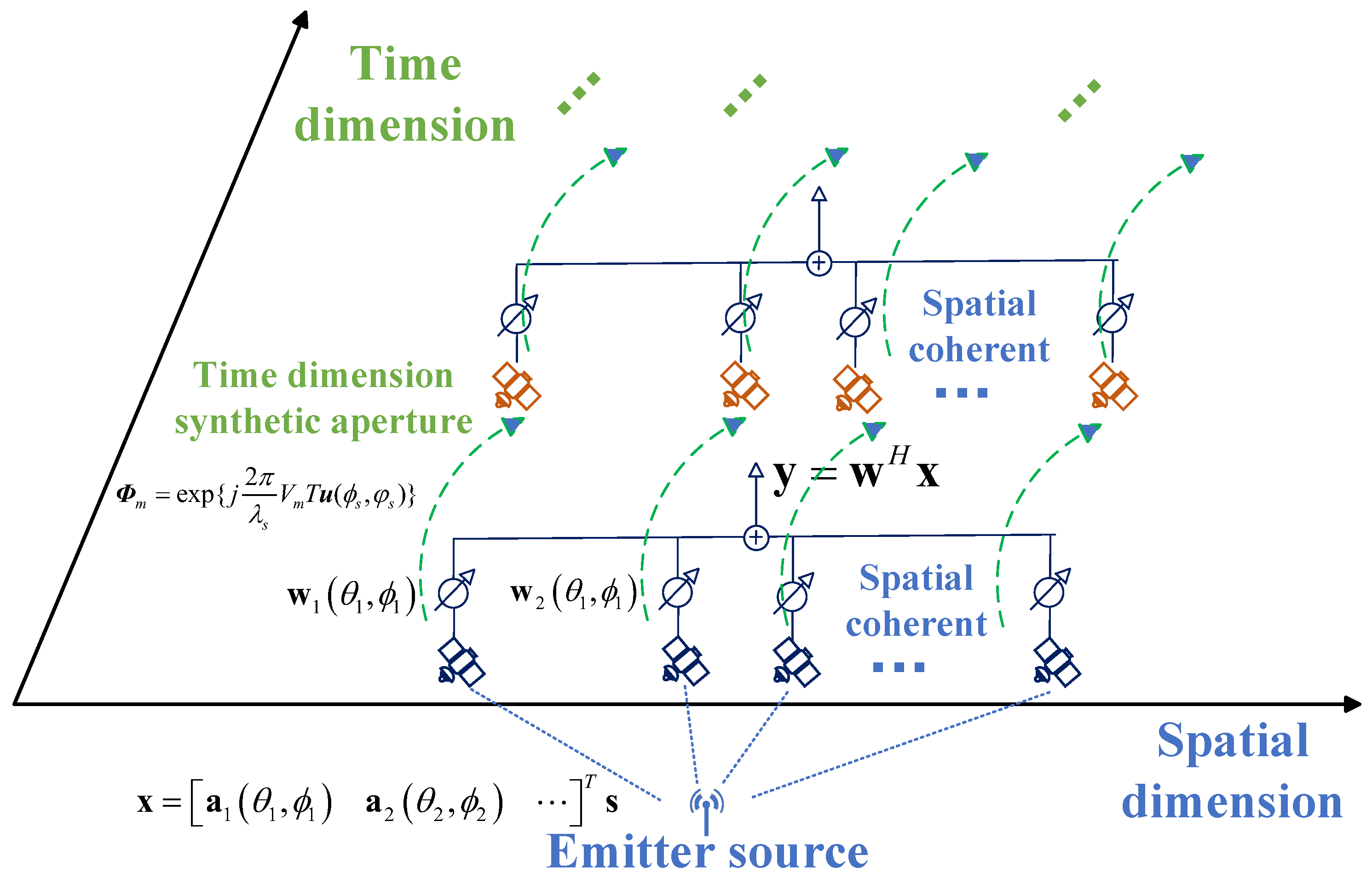
2.3. Signal Model of SADPA System

In the preceding section, we introduced the DPAA scenario. In this subsection, we extend the discussion to the moving-platform scenario and establish the signal model necessary for a long synthetic aperture.
Consider platform m as an example. The three-dimensional moving model is illustrated in Figure 4. We construct a Cartesian coordinate system with point O as the reference. The mth platform moves at a constant velocity V m parallel to the ground in a known direction, traveling from point A to point C during the period from t k 1 to t k + 1 . Furthermore, at time t k , platform m is located at point B, with coordinates given by r m , k ( a ) and displacement given by r m , k + 1 ( a ) . The emitter source is located on the ground with coordinates r ( s ) = [ X s Y s Z s ] where X s and Y s are unknown and Z s is zero. The direction vector from platform m to source S is denoted by r m , k ( a s ) .
The direction vector from the reference point O to the emitter source S is given by u ( ϕ , φ ) , where ϕ is the azimuth angle and φ is the pitch angle, i.e.,
u ( ϕ , φ ) = [ cos ( φ ) cos ( ϕ ) cos ( φ ) sin ( ϕ ) sin ( φ ) ] T
According to (6), the distance r m , k ( a s ) between platform m and emitter source S is given by
r m , k ( a s ) = r ( s ) r m , k ( a ) = r ( s ) 2 + r m , k ( a ) 2 2 r ( s ) r m , k ( a ) u T ( ϕ s , φ s ) u ( ϕ m , k , φ m , k )
where u ( ϕ m , k , φ m , k ) is the direction vector from platform m to the emitter source k. When the distance from the reference point to the emitter is much greater than the distance of the platform, i.e.,  r m , k ( a ) r ( s ) , Equation (7) can be approximated as follows [26]:
| r m , k ( a s ) | = | r ( s ) | r m , k ( a ) u ( ϕ s , φ s )
This approximation separates the unknown parameter u ( ϕ , φ ) from the complex nonlinear equation, facilitating subsequent derivations.
We model the received signal as a single-frequency signal s ˜ ( t ) = s ( t ) exp j 2 π f s t , where s ( t ) represents the signal amplitude and f s denotes the signal frequency. Due to the propagation delay τ m , k , l = r m , k , l ( a s ) r ( s ) c , the received signal at moving platform m at time t k , l is given by
s ˜ m ( t k , l ) = s ( t k , l ) exp { j 2 π f s ( t k , l τ m , k , l ) }
where t k , l denotes the lth sampling time in the kth sampling period, while  r m , k , l ( a s ) is the distance between platform m and the source.
Substituting (8) into (9), the signal received at platform m can be expressed as
y m ( t k , l ) = s ( t k , l ) exp { j 2 π λ s r m , k , l ( a ) u ( ϕ s , φ s ) }
where λ s denotes the wavelength, and  r m , k , l ( a ) represents the coordinates of platform m at time t k , l . The total received signal for the distributed array can be obtained by combining all M outputs:
Y ( t k , l ) = exp { j 2 π λ s r 1 , k , l ( a ) u ( ϕ s , φ s ) } exp { j 2 π λ s r 2 , k , l ( a ) u ( ϕ s , φ s ) } exp { j 2 π λ s r M , k , l ( a ) u ( ϕ s , φ s ) } s ( t k , l ) = a k , l ( ϕ s , φ s ) s ( t k , l )
where a k , l ( ϕ s , φ s ) denotes the steering vector.

3. Localization Algorithm Utilizing SADPA

In the previous section, we detailed the signal model for the received SADPA, where emitter position parameters must be estimated. The complete process of the proposed SADPA localization is depicted in Figure 5. The proposed framework involves a full localization process consisting of K sampling instances, corresponding to K transmission periods T, with l signal samples collected at each instance, resulting in a total of K × l samples. After all K sampling instances are completed, the target source location can be determined using the samples and the current spatial information of the entire array.
The signal model’s establishment relies on the spatial information of each platform at the current time. To fully leverage the ultra-long baseline and long-synthetic-aperture techniques of distributed platforms, it is essential to consider the platforms’ motion characteristics. Subsequently, a direct signal source localization algorithm for the SADPA system based on the aforementioned signal model is introduced.

3.1. Long-Synthetic-Aperture Localization Algorithm for Distributed Moving Platforms

This section introduces the signal processing method for the SADPA system, which comprises a synthetic-aperture technique based on motion compensation and an improved MUSIC-DPD algorithm. The overall algorithm flow is illustrated in Figure 6. Initially, the displacement of the moving platforms between sampling periods is computed, and a compensation factor is derived based on the displacement. Subsequently, the received signal at each platform is phase-shifted according to the compensation factor to achieve virtual aperture synthesis. Finally, the improved MUSIC-DPD algorithm is employed to synchronously estimate both the motion compensation factor and the location of the target source.

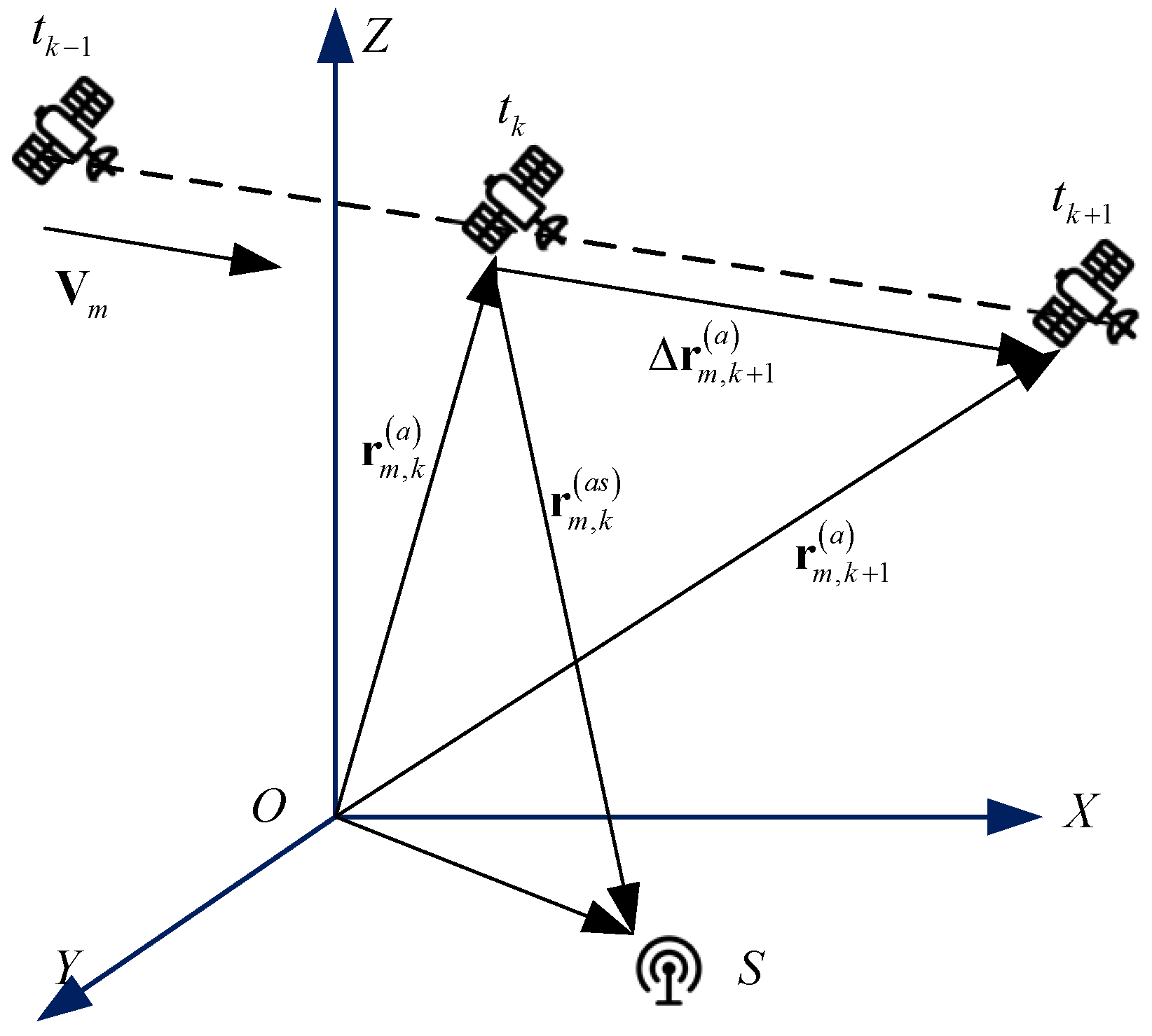
3.2. Long Synthetic Aperture Based on Motion Compensation

The principle of a long synthetic aperture in this work is to phase-shift the received signals in each sampling period to align them with the signals from the previous period using the constructed compensation factor. The phase-shifted signal is equivalent to the received signals of a virtual synthetic array. The ideal received signal in period t k + 1 is denoted as Y ( t k + 1 ) , where r m , k + 1 ( a ) = r m , k ( a ) + r m , k + 1 ( a ) , and  r m , k + 1 ( a ) represents the displacement of platform m during the period from t k to t k + 1 . When the platform moves linearly at a constant speed, r m , k + 1 ( a ) = V m × T , where T is the transmission period, determined by the sampling rate and quantity. The ideal received signal under a single-source scenario is expressed as
Y ( t k + 1 ) = exp { j 2 π λ s r 1 , k ( a ) u ( ϕ s , φ s ) } exp { j 2 π λ s V 1 T u ( ϕ s , φ s ) } exp { j 2 π λ s r 2 , k ( a ) u ( ϕ s , φ s ) } exp { j 2 π λ s V 2 T u ( ϕ s , φ s ) } exp { j 2 π λ s r M , k ( a ) u ( ϕ s , φ s ) } exp { j 2 π λ s V M T u ( ϕ s , φ s ) } s ( t k + 1 )
where the right part of the matrix accounts for the phase change due to platform movement, incorporating the target position u ( ϕ s , φ s ) . The compensation factor is constructed as
Φ m = exp j 2 π λ s t k t k + 1 V m u ( ϕ s , φ s ) + α τ   d τ
where α models the linear frequency drift, enabling precise phase alignment of array signals across the temporal dimension.
The SADPA passive localization method is illustrated in Figure 7. For platform 1, the unified output in the kth period is given by
y 1 ( t k ) = [ y 1 ( t k , 1 ) y 1 ( t k , 2 ) y 1 ( t k , L ) ]
During phase shift processing, the samples in the kth period must be multiplied by a compensation factor Φ 1 to align with the samples in the (k + 1)th period. Similarly, the kth samples need to be multiplied by Φ 1 K k to align with the samples in the final period. The total output of platform 1 after compensation is expressed as
Y 1 = [ y 1 ( t 1 ) Φ 1 K 1 y 1 ( t 2 ) Φ 1 K 2 y 1 ( t K ) Φ 1 K K ]
By analogy, the complete output for M elements is given by
Y = [ Y 1 Y 2 Y M ] T
where the dimension of Y is M × K l .

3.3. Improved MUSIC-DPD Algorithm

The basic principle of spatial spectral estimation involves estimating the auto-correlation matrix from the sampled signal and utilizing the orthogonality between the noise subspace and signal subspace to generate the spatial spectrum. The estimated covariance matrix is expressed as
R ^ xx = Y ^ Y ^ H K
The noise subspace E n can be obtained by performing eigenvalue decomposition on R ^ xx . After the phase of all signals has been compensated as described above, the steering vector for the final period t k is used:
a K ( ϕ , φ ) = exp { j 2 π λ s r 1 , K ( a ) u ( ϕ , φ ) } exp { j 2 π λ s r M , K ( a ) u ( ϕ , φ ) } T
Then, the spatial spectrum can be constructed as
P ( φ , ϕ ) = 1 a K ( ϕ , φ ) H E n E n H a K ( ϕ , φ )
Note that the compensation factor Φ is included in the samples. Thus, we need to synchronously estimate the compensation factor Φ and the emitter source position during the search. The proposed algorithm is shown step by step as Algorithm 1.
Algorithm 1 The steps of the improved MUSIC-DPD algorithm for the SADPA system.
1: Sample and share received signals, and define emitter region of interest.
2: while All the grids are calculated do
3:    Fix a searching grid region, construct the factor Φ .
4:    Construct the compensated sample Y ^ .
5:    Obtain the spectrum power by (19).
6:    Search and calculate next gird region.
7: end while
8: return emitter source position.

3.4. CRB of the Proposed Method

In this subsection, we examine the single-emitter localization performance through CRB derivation. The CRB quantifies the theoretical lower bound for positioning accuracy, determined by algorithm design and SNR. The received signal, after compensation and in the absence of noise, is represented by Equation (20):
Y = Y t 1 Y t 2 Y t K
where Y t k denotes the signal at period t k , compensated to the current time, i.e., after K sampling instances:
Y t k = Φ K k a ϕ s , φ s s t k
Here, the steering vector is given by
a ϕ s , φ s = exp j 2 π λ s r 1 , k ( a ) u ϕ s , φ s exp j 2 π λ s r 2 , k ( a ) u ϕ s , φ s exp j 2 π λ s r M , k ( a ) u ϕ s , φ s
and the phase-shifting matrix Φ is defined as
Φ = e j 2 π λ s V 1 T u ϕ s , φ s 0 0 e j 2 π λ s V M T u ϕ s , φ s
Thus, Equation (20) can be expressed as
Y = Φ K 1 a ϕ s , φ s s t 1 Φ K K a ϕ s , φ s s t K
Including noise, the actual observed output is
Y ^ = Y + N
where N represents the Gaussian white noise. Assuming that the signal is uncorrelated, a single sample y ^ t follows a multidimensional complex Gaussian distribution [37]:
y ^ t C N 0 , R
For the signal model considered in this study,
R = Φ K i a ϕ s , φ s P a H ϕ s , φ s Φ K i H + Q P = E s t 2 Q = E n t n H t
Using the samples, the estimated covariance matrix can be computed as
R = lim N R ^ = lim N 1 N t = 1 N y ^ t y ^ H t
Let b ϕ s , φ s = Φ K i a ϕ s , φ s . For three-dimensional localization, we usually require three parameters: the distance between the source and reference point r , the pitch ϕ s , and the azimuth φ s . Assuming the Z coordinate is unknown, only two parameters are necessary, denoted as θ = ϕ s , φ s . Therefore, the log-likelihood function is given by [38,39]:
ln L y ^ 1 , y ^ 2 , , y ^ N ; θ = const N ln det R t = 1 N y ^ H t R 1 y ^ t
where
t = 1 N y ^ H t R 1 y ^ t = t = 1 N tr R ^ t R 1 t , θ
The number of samples is N = K L . The log-likelihood function satisfies the regularity condition,
E ln L y ^ ; θ i θ i = 0
which allows us to prove
E ln L y ^ ; θ i θ i 2 = E 2 ln L y ^ ; θ i θ i 2
The i , j th element of the Fisher information matrix can be computed as
I i , j θ = N   tr R 1 θ R θ θ i R 1 θ R θ θ j
Note that the covariance matrix R is also a function of the current sampling period t k . Thus, Equation (33) can be specified as
I i , j θ = L k = 1 K tr R 1 θ , t k R θ , t k θ i R 1 θ , t k R θ , t k θ j
Thus, the CRB for the proposed method is given by
CRB i , j θ = I i , j 1 = L k = 1 K b θ i P b H + b P b H θ i R 1 × b θ i P b H + b P b H θ i R 1
where
b ( k ) = Φ K k a = ( K k ) Φ K k × diag j 2 π λ r 0 V 1 T u ( x , y , z ) j 2 π λ r 0 V M T u ( x , y , z ) + Φ

4. Performance Analysis

In this section, we present the simulation results to evaluate the performance of the proposed method for the SADPA system. We analyze our proposed method alongside several other algorithms across different environments.

4.1. Simulation Environment Parameters

The positions of the moving platforms and the emitter source are shown in Figure 8. We consider five low-orbit satellites moving at a speed of approximately 7000 m per second, with the emitter located at the coordinates 0 , 100   km . The initial positions and directions of movement are detailed in Table 1.
The emitter source is located on the earth’s surface. We configure the emitter to transmit a linear frequency-modulated signal with a bandwidth of 0.5 MHz. To examine the proposed method, we employ two types of emitters: communication signals (center frequency of 1.5 GHz) and radar transmitting signals (center frequency of 10 GHz). The number of sampling points per period is set to L = 100 , with a sampling pulse repetition interval of T r = 1   μ s , a sampling pulse width of T = 500 ms, and a sampling period of K = 10 .

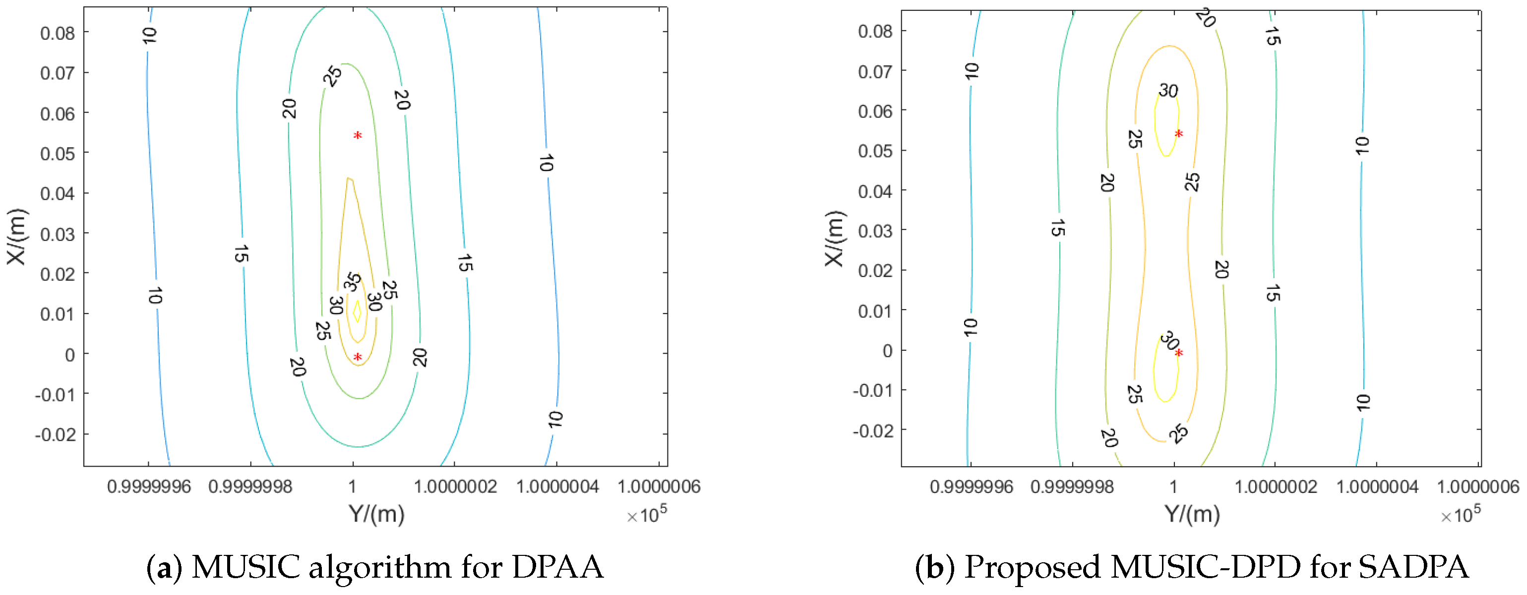
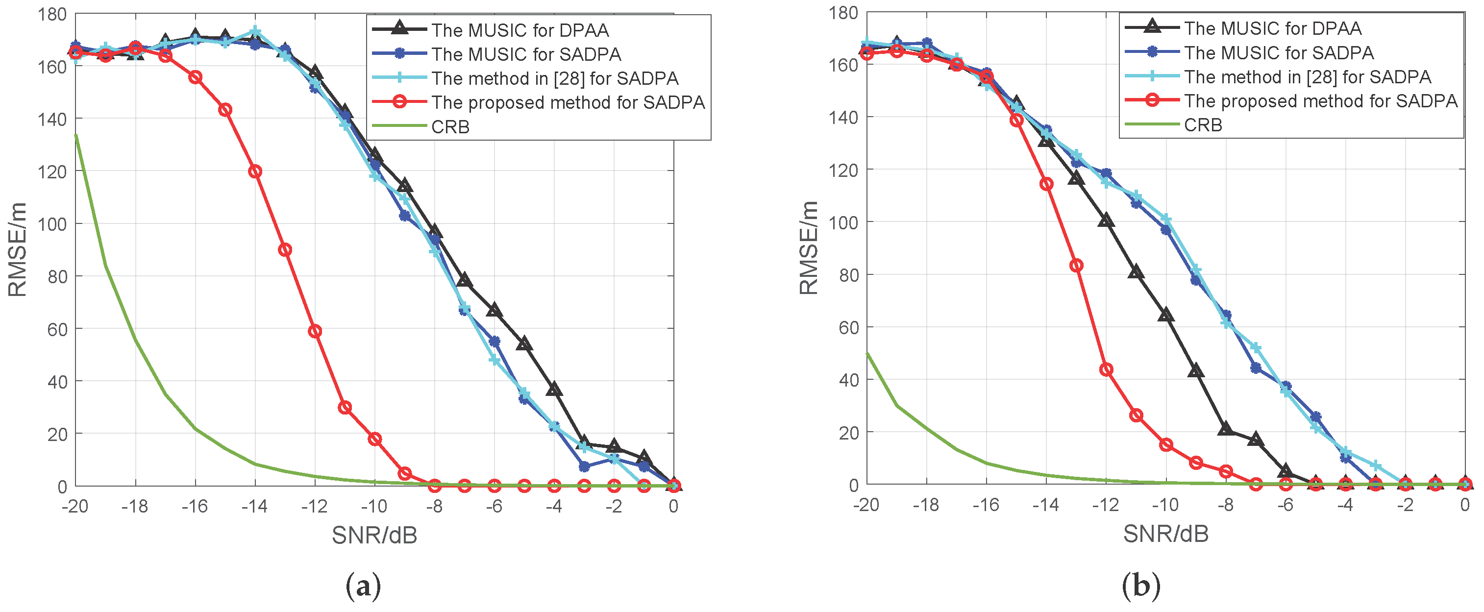
4.2. Simulation Results

Figure 9a illustrates the movement-induced phase shifts of the first coherent platform, while Figure 9b displays the phase alignment after compensation using the improved MUSIC-DPD algorithm. These results demonstrate that platform motion induces phase dispersion across sampling periods, which would otherwise prevent direct synthetic-aperture formation. The compensated phase coherence in Figure 9b confirms the algorithm’s critical role in synthetic processing.
For both communication (1.5 GHz) and radar (10 GHz) signals, we compared the SADPA system using the proposed method with the MUSIC algorithm applied to stationary DPAA systems under identical conditions (0 dB SNR, 0.01 m emitter separation). As shown in Figure 10 and Figure 11, the proposed method successfully distinguishes the two emitters, demonstrating superior resolution compared to DPAA systems without platform motion compensation. At 10 GHz, the method achieves enhanced resolution through utilization of shorter wavelengths while maintaining performance advantages over conventional approaches.
Figure 12 and Figure 13 present the spatial spectrum contour maps, highlighting the coherent gain characteristics. Two emitters, marked as red points, are analyzed in these configurations. Both systems demonstrate over 30 dB signal enhancement in the emitter regions. The emission sources are positioned at each system’s minimum resolvable separation threshold. Consequently, it is observed that the SADPA system can achieve a resolution of 0.012 m under both frequency conditions. In contrast, while the DPAA systems also perform well, achieving a resolution of 0.06 m, they still fall short compared to the SADPA system. From the simulations above, it is evident that the proposed MUSIC-DPD method for the SADPA system can achieve finer localization resolution.
We investigate the localization root mean square errors (RMSEs) in Figure 14, comparing four different methods: (1) the MUSIC algorithm for DPAA systems with 1000 snapshots per platform; (2) the MUSIC algorithm for SADPA systems with 1000 snapshots per platform, with no compensation for movement-induced phase shifts; (3) the method proposed in [33] with 1000 snapshots per platform, where the final estimated position is fused from five platforms; and (4) the proposed MUSIC-DPD method applied to the SADPA system, with a sampling period of K = 100 and L = 100 snapshots per sampling, considering a total of 1000 snapshots. The results indicate that the proposed method outperforms the other algorithms. When comparing the MUSIC-DPD in SADPA with the MUSIC in DPAA, it is evident that the synthetic aperture allows a greater aperture length, thereby enhancing positioning accuracy. Similarly, when comparing the MUSIC-DPD in SADPA with the method proposed in [33], it is shown that the distributed phased signal processing can enhance position accuracy. Additionally, the RMSE results and the derived CRB with respect to input SNRs are presented. The RMSE results of the proposed localization method are close to the corresponding CRB curve. In conclusion, the SADPA system leverages the advantages of DPAA and synthetic-aperture passive localization, achieving more significant performance than other methods.
The results show that the proposed method outperforms other algorithms. Comparing MUSIC-DPD in SADPA systems and MUSIC in DPAA systems, we can observe that a synthetic aperture can create a longer aperture to enhance positioning accuracy. Similarly, comparing MUSIC-DPD and the method proposed in [33], one can observe that distributed platforms enhance multi-source resolution by leveraging ultra-long baselines. In addition, the RMSE results of the proposed localization method are close to the corresponding CRB curve. In conclusion, the SADPA system utilizes advantages of DPAA and synthetic-aperture passive localization, obtaining more significant results than others.

5. Conclusions

In this article, we proposed a long-synthetic-aperture localization framework for distributed coherent moving platforms, known as the SADPA system. This framework combines the advantages of a large coherent aperture from distributed phased arrays with an extended synthetic aperture from platform movement, achieving superior resolution and accuracy in passive localization. To address the phase diffusion caused by array motion, we developed an improved MUSIC-DPD algorithm with phase compensation. For practical implementations, phase coherence across platforms can be maintained through inter-satellite synchronization links, which enable the construction of motion-compensated steering matrices. The simulation results demonstrate that the SADPA framework significantly enhances localization accuracy and resolution, outperforming traditional stationary DPAA systems, particularly in high-frequency conditions. Moreover, the derived CRB validates the effectiveness of the proposed approach, with the RMSEs closely aligning with the CRB. The SADPA system offers a robust solution for high-precision localization, applicable in both civilian and military contexts. In conclusion, the SADPA system effectively combines distributed coherent arrays with synthetic-aperture techniques, providing a promising framework for advanced emitter localization in dynamic environments.

Author Contributions

Methodology, investigation, writing—original draft, X.Z.; Resources, writing–review & edtiting, G.S.; Writing–review & edtiting, Z.L.; Software, D.L., Z.L. and Y.J. All authors have read and agreed to the published version of the manuscript.

Funding

This work was supported in part by the National Natural Science Foundation of China under Grant No. 62201371.

Data Availability Statement

Data is contained within the article.

Conflicts of Interest

The authors declare no conflicts of interest.

References

  1. Jung, D.H.; Kim, D.H.; Azim, M.T.; Park, J.; Park, S.O. A novel signal processing technique for Ku-band automobile FMCW fully polarimetric SAR system using triangular LFM. IEEE Trans. Instrum. Meas. 2020, 70, 1–10. [Google Scholar] [CrossRef]
  2. Renga, A.; Graziano, M.D.; Moccia, A. Formation flying SAR: Analysis of imaging performance by array theory. IEEE Trans. Aerosp. Electron. Syst. 2020, 57, 1480–1497. [Google Scholar] [CrossRef]
  3. Huang, L.; Liu, G. Convolutional feature aggregation network with self-supervised learning and decision fusion for SAR target recognition. IEEE Trans. Instrum. Meas. 2024, 73, 2526714. [Google Scholar] [CrossRef]
  4. Renga, A.; Gigantino, A.; Graziano, M.D. Multi-Platform Image Synthesis for Distributed Synthetic Aperture Radar in Long Baseline Bistatic Configurations. IEEE Trans. Aerosp. Electron. Syst. 2023, 59, 9267–9284. [Google Scholar] [CrossRef]
  5. Cerutti-Maori, D.; Sikaneta, I.; Klare, J.; Gierull, C.H. MIMO SAR processing for multichannel high-resolution wide-swath radars. IEEE Trans. Geosci. Remote Sens. 2013, 52, 5034–5055. [Google Scholar] [CrossRef]
  6. Lombardo, P.; Pastina, D.; Turin, F. Ground moving target detection based on MIMO SAR systems. IEEE J. Sel. Top. Appl. Earth Obs. Remote Sens. 2015, 8, 5081–5095. [Google Scholar] [CrossRef]
  7. Yeredor, A.; Angel, E. Joint TDOA and FDOA estimation: A conditional bound and its use for optimally weighted localization. IEEE Trans. Signal Process. 2010, 59, 1612–1623. [Google Scholar] [CrossRef]
  8. Cao, S.; Chen, X.; Zhang, X.; Chen, X. Combined weighted method for TDOA-based localization. IEEE Trans. Instrum. Meas. 2019, 69, 1962–1971. [Google Scholar] [CrossRef]
  9. Yang, Y.; Zheng, J.; Liu, H.; Ho, K.; Yang, Z.; Gao, S. Optimal Sensor Placement and Velocity Configuration for TDOA-FDOA Localization and Tracking of a Moving Source. IEEE Trans. Aerosp. Electron. Syst. 2024, 60, 8255–8272. [Google Scholar] [CrossRef]
  10. Hassan, E.S.; Alharbi, A.A.; Oshaba, A.S.; El-Emary, A. Enhancing smart irrigation efficiency: A new WSN-based localization method for water conservation. Water 2024, 16, 672. [Google Scholar] [CrossRef]
  11. Weiss, A.J. Direct position determination of narrowband radio frequency transmitters. IEEE Signal Process. Lett. 2004, 11, 513–516. [Google Scholar] [CrossRef]
  12. Lin, C.; Huang, C.; Su, Y. A coherent signal processing method for distributed radar system. In Proceedings of the 2016 Progress in Electromagnetic Research Symposium (PIERS), Shanghai, China, 8–11 August 2016; pp. 2226–2230. [Google Scholar]
  13. Weiss, A.J.; Amar, A. Direct position determination of multiple radio signals. EURASIP J. Adv. Signal Process. 2005, 2005, 653549. [Google Scholar] [CrossRef]
  14. Cuomo, K.; Coutts, S.; McHarg, J.; Pulsone, N.; Robey, F. Wideband aperture coherence processing for next generation radar (NexGen). MIT Linc. Lab. 2004, 2, 810-005. [Google Scholar]
  15. Fletcher, A.S.; Robey, F.C. Performance bounds for adaptive coherence of sparse array radar. In Proceedings of the 12th Annual Workshop on Adaptive Sensor Array Processing, Lexington, MA, USA, 16–18 March 2004. [Google Scholar]
  16. Zeng, T.; Yin, P.; Liu, Q. Wideband distributed coherent aperture radar based on stepped frequency signal: Theory and experimental results. IET Radar Sonar Navig. 2016, 10, 672–688. [Google Scholar] [CrossRef]
  17. Zhang, Z.; Meng, W.; Song, M.; Zhao, Z.; Li, F.; Feng, X.; Zhao, Y. Multi-domain extended ELM-DOA subarray localization method based on distributed coherent aperture radar. IEEE Trans. Veh. Technol. 2023, 73, 3469–3484. [Google Scholar] [CrossRef]
  18. Oispuu, M.; Nickel, U. 3D passive source localization by a multi-array network: Noncoherent vs. coherent processing. In Proceedings of the 2010 International ITG Workshop on Smart Antennas (WSA), Bremen, Germany, 23–24 February 2010; pp. 300–305. [Google Scholar]
  19. Godrich, H.; Haimovich, A.M.; Blum, R.S. Target localization accuracy gain in MIMO radar-based systems. IEEE Trans. Inf. Theory 2010, 56, 2783–2803. [Google Scholar] [CrossRef]
  20. Hadaschik, N.; Sackenreuter, B.; Schäfer, M.; Faßbinder, M. Direct positioning with multiple antenna arrays. In Proceedings of the 2015 International Conference on Indoor Positioning and Indoor Navigation (IPIN), Banff, AB, Canada, 13–16 October 2015; pp. 1–10. [Google Scholar]
  21. Scherhäufl, M.; Pichler, M.; Stelzer, A. UHF RFID localization based on phase evaluation of passive tag arrays. IEEE Trans. Instrum. Meas. 2014, 64, 913–922. [Google Scholar] [CrossRef]
  22. Vukmirović, N.; Erić, M.; Janjić, M.; Djurić, P.M. Direct wideband coherent localization by distributed antenna arrays. Sensors 2019, 19, 4582. [Google Scholar] [CrossRef]
  23. Vukmirović, N.; Janjić, M.; Djurić, P.M.; Erić, M. Position estimation with a millimeter-wave massive MIMO system based on distributed steerable phased antenna arrays. EURASIP J. Adv. Signal Process. 2018, 2018, 1–17. [Google Scholar] [CrossRef]
  24. Garcia, N.; Wymeersch, H.; Larsson, E.G.; Haimovich, A.M.; Coulon, M. Direct localization for massive MIMO. IEEE Trans. Signal Process. 2017, 65, 2475–2487. [Google Scholar] [CrossRef]
  25. Schmidt, R. Multiple emitter location and signal parameter estimation. IEEE Trans. Antennas Propag. 1986, 34, 276–280. [Google Scholar] [CrossRef]
  26. Friedlander, B. Localization of signals in the near-field of an antenna array. IEEE Trans. Signal Process. 2019, 67, 3885–3893. [Google Scholar] [CrossRef]
  27. Zhang, G.; He, X.; Wang, L.; Yang, D.; Chang, K.; Duffy, A. Step frequency TR-MUSIC for soft fault detection and location in coaxial cable. IEEE Trans. Instrum. Meas. 2023, 72, 1–11. [Google Scholar] [CrossRef]
  28. Demissie, B.; Oispuu, M.; Ruthotto, E. Localization of multiple sources with a moving array using subspace data fusion. In Proceedings of the 2008 11th International Conference on Information Fusion, Cologne, Germany, 30 June–3 July 2008; pp. 1–7. [Google Scholar]
  29. Oispuu, M.; Nickel, U. Direct detection and position determination of multiple sources with intermittent emission. Signal Process. 2010, 90, 3056–3064. [Google Scholar] [CrossRef]
  30. Wang, D.; Zhang, G. A direct localization method for moving narrowband source based on Doppler frequency shifts. Acta Electron. Sin. 2017, 45, 591–598. [Google Scholar]
  31. Wu, G.; Zhang, M.; Guo, F.; Xiao, X. Direct position determination of coherent pulse trains based on Doppler and Doppler rate. Electronics 2018, 7, 262. [Google Scholar] [CrossRef]
  32. Autrey, S.W. Passive synthetic arrays. J. Acoust. Soc. Am. 1988, 84, 592–598. [Google Scholar] [CrossRef]
  33. Zhang, L.; Huan, H.; Tao, R.; Wang, Y. Emitter localization algorithm based on passive synthetic aperture. IEEE Trans. Aerosp. Electron. Syst. 2021, 58, 2687–2701. [Google Scholar] [CrossRef]
  34. Wang, Y.; Sun, G.c.; Xing, M.; Xiang, J.; Zhang, Z.; Guo, L. Long Synthetic Aperture Passive Localization Using Azimuth Chirp-Rate Contour Map. In Proceedings of the IGARSS 2020-2020 IEEE International Geoscience and Remote Sensing Symposium, Waikoloa, HI, USA, 26 September–2 October 2020; pp. 928–931. [Google Scholar]
  35. Chen, B.; Wang, Y.; Sun, G.C.; Xing, M.; Zhang, Z.; Yang, X. A Long Synthetic Aperture Passive Localization Method Using Two Planes. In Proceedings of the 2021 CIE International Conference on Radar (Radar), Haikou, China, 15–19 December 2021; pp. 767–769. [Google Scholar]
  36. Wang, Y.; Sun, G.C.; Zhang, X.; Yang, J.; Wang, A.; Xing, M.; Yang, X. An Ultra High Resolution Positioning Algorithm for Satellite Ultra Long Duration Data Based on Synthetic Aperture Technique. IEEE Trans. Geosci. Remote. Sens. 2024, 62, 5209512. [Google Scholar] [CrossRef]
  37. Stoica, P.; Nehorai, A. Performance study of conditional and unconditional direction-of-arrival estimation. IEEE Trans. Acoust. Speech Signal Process. 1990, 38, 1783–1795. [Google Scholar] [CrossRef]
  38. Zhang, X.; Cheng, Y.; Shang, X.; Liu, J. CRB analysis for mixed-ADC based DOA estimation. IEEE Trans. Signal Process. 2024, 72, 3043–3058. [Google Scholar] [CrossRef]
  39. Hung, H.s.; Kaveh, M. On the statistical sufficiency of the coherently averaged covariance matrix for the estimation of the parameters of wideband sources. In Proceedings of the ICASSP’87. IEEE International Conference on Acoustics, Speech, and Signal Processing, Dallas, TX, USA, 6–9 April 1987; Volume 12, pp. 33–36. [Google Scholar]
Figure 1. Collaborative scanning mode of distributed platforms.
Electronics 14 02114 g001
Figure 2. Signal acquisition and utilization mode.
Electronics 14 02114 g002
Figure 3. Coherent signal processing by DPAA systems.
Electronics 14 02114 g003
Figure 4. The three-dimensional model of the moving platform.
Electronics 14 02114 g004
Figure 5. Schematic of SADPA.
Electronics 14 02114 g005
Figure 6. Flow chart of SADPA system signal processing.
Electronics 14 02114 g006
Figure 7. Schematic diagram of synthetic-aperture method based on motion compensation.
Electronics 14 02114 g007
Figure 8. Distributed mobile platform and signal source location diagram.
Electronics 14 02114 g008
Figure 9. Phase shifts before and after receiving signal compensation for moving platform 1. (a) Signal phase of each sampling period before compensation. (b) Signal phase of each sampling period after compensation.
Electronics 14 02114 g009
Figure 10. Comparison of localization resolution performance for 1.5 GHz signal sources.
Electronics 14 02114 g010
Figure 11. Comparison of localization resolution performance for 10 GHz signal sources.
Electronics 14 02114 g011
Figure 12. Normalized cost function contour plot for a 1.5 GHz signal source.
Electronics 14 02114 g012
Figure 13. Normalized cost function contour plot for a 10 GHz signal source.
Electronics 14 02114 g013
Figure 14. Performance of methods regarding localization error at different SNRs. (a) The estimate error of emitter position RMSE (m) for 1.5 GHz signals. (b) The estimate error of emitter position RMSE (m) for 10 GHz signals.
Electronics 14 02114 g014
Table 1. Initial coordinates and orientation angles of each platform.
X Coordinate (km)Y Coordinate (km)Z Coordinate (km)
−217.96112.46896.18
8.06154.18903.48
−139.76181.53889.68
177.8786.01706.18
−71.69−36.59706.08
Disclaimer/Publisher’s Note: The statements, opinions and data contained in all publications are solely those of the individual author(s) and contributor(s) and not of MDPI and/or the editor(s). MDPI and/or the editor(s) disclaim responsibility for any injury to people or property resulting from any ideas, methods, instructions or products referred to in the content.

