Abstract
The environmentally friendly insulating gas C4F7N/CO2 has become a popular alternative to the insulating gas SF6 in recent years. The internal structure of electrical equipment should be taken into account in normal operation, and its electric field distribution is designed and manufactured according to a slightly non-uniform electric field. A large number of high-voltage experiments are usually needed to study the impulse discharge voltage of gases, while new environmentally friendly insulating gases are expensive and have a large amount of experience. The current calculation model of gas discharge voltage is only suitable for special gases, and the calculation conditions (electric field non-uniformity, air pressure, polarity) are specific, making it difficult to match engineering. In this paper, the calculation model of impulse discharge voltage is established with a sphere–plane electrode in a slightly non-uniform electric field, and the calculation formula for key parameters is deduced. SF6 gas and C4F7N/CO2 mixed gas were used as cases to calculate, and the calculation model was verified to be effective via comparison with the experiment.
1. Introduction
In electrical equipment, gas insulation materials such as air, nitrogen, SF6, and other gases are commonly used, among which SF6 is used in large amounts in electrical equipment due to its excellent insulation and arc extinguishing performance [1]. But, since SF6 has a greenhouse effect potential of about 23,900 times that of CO2 and a lifetime of about 3200 years in the atmosphere, it has been listed as one of the restricted greenhouse gases as early as 1997 in the Kyoto Protocol [2]. For example, the East China UHV AC ring network, divided into two and a half rings north and south, is the world’s first UHV AC double-ring network. The SF6 usage of the Huainan North Zhejiang Shanghai 1000 kV AC UHV Project is 19 t/km, accumulating 665 t [3]. The greenhouse effect, considering only the natural rate of gas leakage, includes 16,000 tons of CO2 being emitted into the atmosphere each year. In order to reduce the amount of SF6 used, there is an urgent need to find environmentally friendly insulating gases with satisfactory physical and chemical properties. In recent years, C4F7N/CO2 gas has become a popular candidate for SF6 replacement gases with good physical and chemical properties and high insulation strength. According to research by Yannick Kieffel’s team at the United States Department of Materials and Technology, Wuhan University in China, Xi’an Jiaotong University, North China Electric Power University [4,5,6,7,8,9], the C4F7N/CO2 greenhouse effect potential value is below 2100 (no more than 9% of the SF6), the ozone depletion potential value is zero, and the power frequency, lightning impulse insulation strength reaches more than 80% of the SF6 when the 9% C4F7N/91% CO2 mixture meets the condition of liquification at a temperature of −15 °C. C4F7N was first commercialized and scaled up for use by 3M in Minnesota in the United States, and the new environmentally friendly insulating gas was also developed and synthesized by Yuji, a domestic gas company, but the cost of synthesis and purification remains high.
Obtaining gas discharge voltage usually requires a large number of high-voltage experiments and different engineering application scenarios make the electrode parameters and gas parameters different, resulting in a large number of experiments that are time-consuming and labor-intensive. There are usually several deficiencies: (1) High-voltage gas discharge experiments have significant requirements for high voltage, ultra-high voltage power sources, and various equipment (high equipment cost), among others; (2) The synthesis and purification of new, environmentally friendly insulating gases is expensive, with significant gas consumption and expense; (3) Experiments were unable to account for the environment of slightly non-uniform electric fields at different sizes, and problems such as different electrode sizes, gap distances used by researchers in various teams, and difficulty in comparisons emerged. Therefore, there is an urgent need for a relatively general computational model to reduce the number of experiments, improve engineering design efficiency, and save costs. At present, the calculation model and method of gas impulse discharge voltage is only suitable for special gases, and calculation conditions such as electric field non-uniformity, air pressure, and polarity are fixed and cannot match the actual engineering conditions.
The difference between different calculation methods is shown in Table 1. Researchers at Shanghai Electric Power Institute have used electrostatic fields to numerically calculate the impulse discharge voltages of dry air and nitrogen [10], but this method cannot compute changes caused by changes in voltage polarity, different air pressures, and changes in electrode parameters. Northeast Electric Power University researchers calculated the SF6 reduced field strength of the CF3I/N2 mixed gas based on the binomial approximate solution of the Boltzmann equation. Their analysis was limited to a uniform electric field and did not consider the environment for specific engineering applications [11]. He Junjia’s team at Huazhong University of Science and Technology calculated the streamer discharge voltage of CF3I/N2 mixed gas under a sphere–plane electrode configuration using the streamer criterion [12]. Ruanjiang’s team at Wuhan University calculated the breakdown voltage of air under a sphere–plane electrode configuration using the SVM method and the streamer criterion [13], respectively, but both were limited to the specific electric field environment, specific gas, air pressure, and other conditions, without considering the effects of multiple factors, and the calculation was less efficient.

Table 1.
The difference between different calculation methods.
For electrical equipment using environmentally friendly insulating gases such as C4F7N/CO2, the internal structure of the equipment must be taken into account when the electrical equipment is in normal operation, and the electric field distribution inside it is designed and manufactured in accordance with slightly non-uniform electric fields. Therefore, obtaining the discharge voltage of gases in slightly non-uniform fields has important application value for electrical equipment insulation design. In this paper, the calculation model of impulse discharge voltage of environmental protection insulation gas is established in the form of a typical sphere–plane electrode in a slightly non-uniform electric field (the non-uniformity of the electric field can be adjusted), several key parameter formulas are deduced, and the calculation model—which can change the electrode parameters, voltage polarity, air pressure parameters, and gas species—is more suitable for an engineering application environment. Through the case of SF6 gas and C4F7N/CO2 mixed gas, the calculation results proposed are verified via comparison with the experimental data of gas in the same conditions.
2. Method of Calculating Impulse Discharge Voltage
To solve the above problems, this paper provides a calculation model of impulse discharge voltage of environmentally friendly insulation gas in a slightly non-uniform electric field environment, which can quickly and accurately calculate the problem of gas impulse discharge, overcome the relevant limitations of experiments, and reduce the number of experiments, time costs, and economic costs. A calculation model for impulse discharge voltage of environmentally friendly insulating gases in slightly non-uniform electric fields is proposed, and the critical charge accumulation coefficient Mcr is defined, which is related to the effective ionization coefficient of different gases and the critical electron avalanche length of different gases. The critical charge accumulation coefficient Mcr is calculated, then the impulse discharge voltage of gases under different conditions is calculated. The key inputs of the calculation are voltage polarity, electric field distribution function, electrode geometry parameters, high voltage value, and gas pressure. The derivation, calculation, and simulation results of each step are given. The typical insulation gas SF6 and the new environmental protection insulation gas are calculated under different parameters and compared with the experimental data of high voltage discharge under the same conditions. The error is less, and the effectiveness of the calculation model is verified. The existing calculation model can only calculate specific gas, specific electric field parameters of the gas impulse discharge voltage problem, and electric field non-uniformity, and the gas pressure parameters can match the actual engineering equipment, improving the efficiency of insulation design and saving costs.
The overall calculation and verification process is shown in Figure 1. The specific steps are as follows:
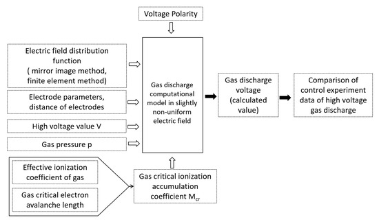
Figure 1.
Calculation flowchart.
- (1)
- Boltzmann equation calculation or SST test to obtain effective ionization coefficient.
- (2)
- When = 0, enter different air pressures to find the critical electric field intensity of the gas at different air pressures.
- (3)
- The radius of curvature, r, of the spherical electrode; the electrode spacing, d, between the spherical and flat electrodes; and the high voltage, V, in a slightly non-uniform electric field environment were input. The electric field distribution was obtained by comparing the image method and the finite element method, and the critical electron avalanche length was calculated from the gas discharge theory.
- (4)
- According to the effective ionization coefficient of the gas, a small amount of experimental data, and the critical electron avalanche length, the critical charge accumulation coefficient Mcr is calculated. If the above parameters are input into the calculation model and the gas discharge meets the discharge condition, the discharge voltage of the gas under this condition can be obtained.
- (5)
- Through gas impulse discharge experiments with different air pressures, voltage polarities, electrode parameters, etc., the calculated results are verified experimentally, and the error is small, meeting the engineering requirements.
The non-uniformity factor f is defined as follows:
The electrode configurations (sphere–plate) simulate uniform (f ≈ 1), slightly non-uniform (1 < f < 2), and highly non-uniform (f > 4) electric fields. The highly non-uniform (f > 4) electric field is used to simulate faults in electrical equipment. The electric field non-uniformity range of the object studied in this article is between 1.05–1.35, which belongs to a slightly non-uniform electric field.
3. Calculating the Gas Critical Ionization Accumulation Coefficient Mcr
By obtaining the effective ionization coefficient and the critical electron avalanche length, the gas critical ionization accumulation coefficient Mcr is calculated.
3.1. Effective Ionization Coefficient
The effective ionization coefficients of different kinds of gases can be calculated using the Boltzmann equation. The Boltzmann equation is given in Formula (3) as the distribution function f(r, v, t) of a particle in the six-dimensional phase space (r, v), r is position coordinate information, v is velocity, and t is time. The equation assumes that the particle’s velocity v is independent of position r. The acceleration of the particle is a = F/m, also independent of the position r. The right-hand side of the equation is the collisional term parameter, taking into account the effect of collisional processes on the distribution function [14].
There are seven variables, namely x, y, z, vx, vy, vz, and t in Equation (1). Therefore, a simplified solution commonly used is the binomial approximation method. This method first simplifies and approximates f into a 0th order term and a 1st order term. Assuming that the 0th order term of the distribution function f is isotropic f0e, which is only a function of velocity, and the 1st order term represents the cylindrical axis symmetric anisotropy f1e of the electronic distribution function f, its magnitude represents the degree of anisotropy, indicating the directionality of anisotropy. Assuming that this direction is the z-direction, the expression is shown in Formula (4). Using the two-term approximation [15,16], f is simplified to yield Equation (4).
The main collisional cross sections of SF6 were obtained from nl. lxcat.net, and the reduced ionization coefficient and reduced absorption coefficient of insulation gas SF6 were simulated with software Bolsig+ 2016 (see Figure 2), then the reduced effective ionization coefficient could be obtained using Formula (5).
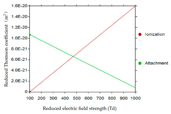
Figure 2.
Bolsig+ calculates the reduced ionization, absorption coefficient of SF6.
Environmentally friendly insulation gas C4F7N/CO2 can be obtained via the SST experiment [17]. The SST test results for the effective ionization coefficient of the new environmentally friendly insulation gas C4F7N/CO2 show a linear growth trend, giving the following Expression (6). N is the number density of gas particles.
From the data fit of the experiment [17], the following is known:
Multiplying both sides of Formula (6) by (N/P) simultaneously yields the following:
Let Formula (4), the effective ionization coefficient/n, be equal to 0. The critical reduced electric field strength (E/N)cn of the gas can be found using the equation of the state of the ideal gas, with the reduced effective ionization coefficient calculation given in Formula (9):
3.2. Critical Electron Avalanche Length Xcr Calculation
In this paper, the axial electric field distribution of the sphere–plane electrode gap is calculated using two methods, and the formula for the critical electron avalanche length is derived from the gas discharge theory formula.
3.2.1. Calculating Electric Field Distribution
- Mirror image method
An identical sphere electrode 2, symmetrical to sphere electrode 1, is placed on the opposite side of the flat plane, equivalently distributing the charge on the originally distributed flat plane over sphere electrode 2 such that the original electric field between the sphere and plane is equal to the electric field vector between the two spheres. As shown in Figure 3, the C point in the figure is any point on the electric field of the electrode axis at a distance of X from the spherical electrode 1, a radius of r, and a distance, d, from the plane electrode. Formulas (10)–(12) [18,19,20] can be obtained.
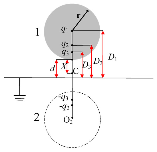
Figure 3.
Mirror image method of sphere–plane electrodes.
The electrostatic force constant k = 9.0 × 10⁹ N·m2/C2. Ε = εrε0. The relative dielectric constant of gas is approximately 1. ε0 = 8.85 × 10⁻¹² F/m.
The electric field intensity at the C point is equivalent to the superimposition of the electric field at the C point by an infinite number of charges:
As n increases, the charge decreases gradually, and the latter term has less influence, simplifying to Equation (14):
Combining the latter two parameters in parentheses into parameter b yields Equation (15) as an expression for the sphere–plane electric field:
- Finite element method
The second method is finite element simulation.
We set the voltage V of the sphere electrode in the diagram to 30 kV, the plate electrode to ground, and the electrode material to copper. When simulating the COMSOL 6.1 electrostatic field, only the relative dielectric constant of the gas needs to be set. The relative dielectric constant of gases such as air, SF6, and CO2 is 1.00 when rounded to two decimal places, which means that the relative dielectric constant of the gas is almost always 1.00. Therefore, the relative dielectric constant of the C4F7N/CO2 mixed gas is also set to 1.00 here.
The 3D electric field simulation selected an electrostatic field module. The selected simulation boundary is a gas space; a cylindrical axisymmetric boundary with a height of 10 cm and a diameter of 8 cm. The boundary condition is that the outer edge of the simulated cylinder has zero charge, and the simulation is carried out according to the steady-state charge conservation.
The electric field simulation results are shown in Figure 4 below. It can be seen from the diagram that the maximum electric field strength is at the surface close to the sphere electrode, and further away from the sphere electrode, its electric field strength is decreasing. Let the distance of the spherical electrode from any point on the plane electrode axis to the spherical electrode be X, as shown in Figure 5. It can be seen that the analytical formula derived using the image method gives results that are essentially in agreement with the finite element simulation results. The relationship between the difference in electric field strength values obtained using these two methods and the variable X is shown in Figure 5. It can be seen that the maximum error is around X being 0–0.25 mm. We have provided the maximum error percentage, which is approximately 8.3%.
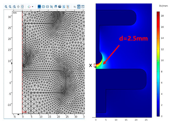
Figure 4.
Electric field distribution simulation of sphere–plane electrode gap.
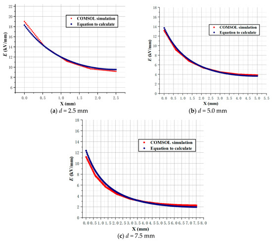
Figure 5.
Comparison of electric field distribution calculation results between image method and finite element simulation.
3.2.2. Derivation of the Critical Electron Avalanche Length
Transforming the electric field Expression (15) gives Formula (16) for the critical electron avalanche length:
According to the gas discharge current beam theory, the initial electron avalanche begins at a distance of from the spherical electrode Xcr where the ionization coefficient is equal to the electron’s attachment coefficient, while distances less than Xcr involve the ionized part, and the ionization coefficient is greater than the electron’s absorption coefficient [21,22]. At the boundary of the corona layer, the ionization coefficient is equal to the electron’s attachment coefficient, and the number of free electrons produced by collisional ionization does not continue to increase to stop ionization, so the critical electron avalanche length is the distance from the starting point of the initial electron avalanche to the spherical electrode, with the effective ionization coefficient = 0.
The expression for the critical electron avalanche length Xcr is derived by substituting the critical breakdown field strength Ecr from Equations (16) and (17):
Given the critical breakdown field strength Ecr (SF6) of gas SF6 = 8.8 kV/(mm·bar), Ecr (SF6) = 8.8 kV/mm at P = 0.1 MPa, and the critical electron avalanche length Xcr at different applied voltages can be calculated using the image method. The following Table 2 is obtained at input voltages of 15 kV and 16 kV.

Table 2.
Critical electron avalanche length Xcr calculation results.
3.3. Calculating the Critical Ionization Accumulation Coefficient Mcr
Based on the conditions from the onset of the streamer in gas discharge theory, the following Expression (19) is obtained [23]:
After making the transformation, we obtain the following Expression (20):
In this paper, the right-hand side ln(Ncr) of Equation (20) is defined as the ionization accumulation coefficient M, which is substituted into the expression of the effective ionization coefficient to obtain Equation (21):
As a high voltage discharge has occurred, the value of M calculated from the discharge voltage V—obtained from experiments with high voltage gas discharges of different polarities—is the gas critical charge accumulation coefficient Mcr under different conditions. For example, using SF6 gas breakdown test data and Equation (21) to calculate the critical charge accumulation coefficient for different gases requires the following three steps.
In the first step, the high voltage discharge voltage test data V are substituted into the calculation formula, then the electrode parameters are substituted into the analytical formula of the electric field distribution to calculate the parameter charges q and b.
The second step, through SST tests, Bolsig+ is used to simulate the reduced effective ionization coefficient of gases to obtain parameters A1, B1.
In the third step, the critical electron avalanche length Xcr is obtained by substituting the pressure and temperature into Equation (15) and the above data into Equation (18) to obtain the critical charge accumulation coefficient Mcr.
The Mcr for different gases under power–frequency voltages and different polar impulse voltages can be obtained using the above steps, see Table 3.

Table 3.
The critical charge accumulation coefficient Mcr.
4. Comparison of the Calculated Results of Gas Impulse Voltage Discharge: Voltage Calculation Model with Experiments
The gas impulse voltage discharge voltage calculation model is essentially derived from the classical gas streamer discharge theory; see Equation (17). Then, Equation (22) is derived from the above Equations (9), (15) and (18). The detailed process is shown in Figure 6
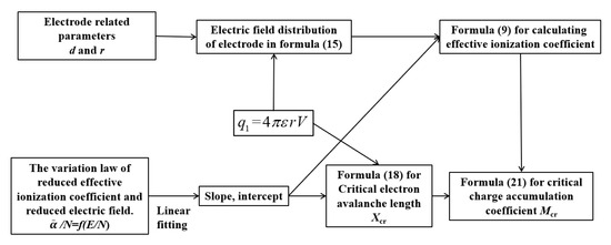
Figure 6.
Step-by-step block diagrams.
According to the calculation flow chart in Figure 1, the voltage polarity parameters, electric field distribution, electrode parameters, experimental values of the high-voltage part, gas pressure, effective ionization coefficient of gas, and critical electron avalanche length of gas are input into the slightly non-uniform electric field discharge calculation model to calculate the value of gas discharge voltage, which is then compared with the data provided by the high-voltage gas discharge control experiment under the same conditions.
The experimental platform and experimental electrodes are shown in Figure 7 and Figure 8. In order to obtain a breakdown voltage under the impulse voltage, the impulse breakdown test was conducted using the voltage boosting method proposed in IEC 60060-1 [24], with at least 20 effective breakdowns occurring in each group.
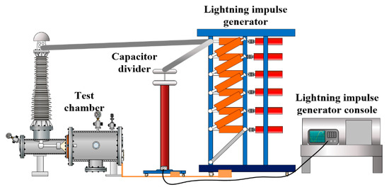
Figure 7.
Impulse discharge voltage experimental platform.
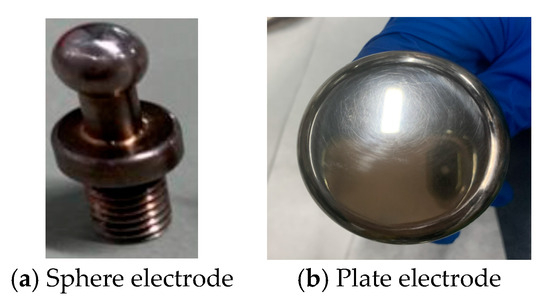
Figure 8.
Experimental electrodes.
- SF6 gas
The lightning impulse 50% breakdown voltage of the SF6 gas gap at an atmospheric pressure of 0.1 MPa and a high pressure of 0.5 MPa with a spherical electrode radius of curvature r = 3 mm and sphere–plane electrode spacing d = 5 mm was calculated and compared with the test values. Ss shown in Figure 7, it can be seen that for a typical insulated gas, SF6, the maximum relative error is 5.1%, meeting engineering requirements. The difference between the calculated and experimental results is shown in Figure 9.
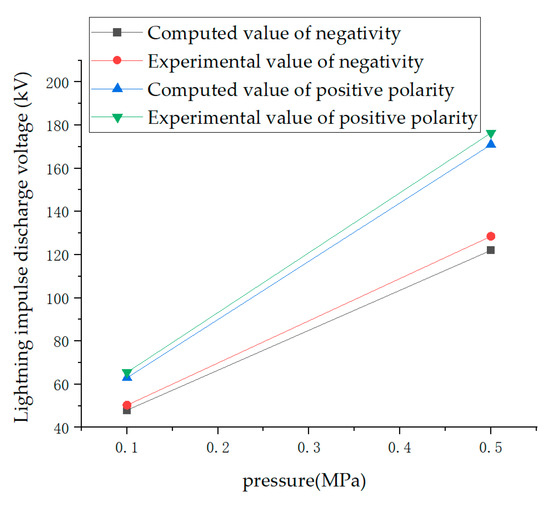
Figure 9.
Calculation and experimental comparison of SF6 gas with different pressures and voltage polarities at a distance d = 5 mm between electrodes.
- 9% C4F7N/91% CO2 mixed gas
This mixture ratio was chosen because of its power frequency, impulse insulation properties close to typical insulation gas SF6, good environmental protection, and suitable liquification temperature. The C4F7N/CO2 sphere–plane electrode lightning impulse discharge voltage at this mixed ratio was calculated according to the calculation flow in Figure 1. For a sphere–plane electrode radius of curvature r = 3 mm and sphere–plane electrode spacing d = 2.5, the calculation results at pressures of 0.3, 0.4, and 0.5 MPa for normal operating ranges of common electrical equipment and a comparison of the results of high-voltage gas discharge experiments are shown in Figure 10, and the specific errors% are shown in Table 4.
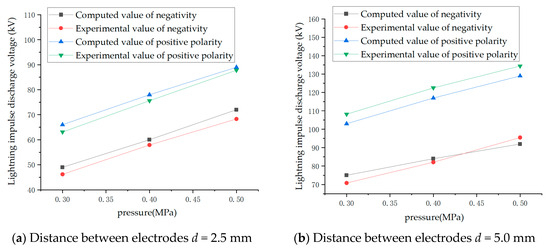
Figure 10.
Calculation and experimental comparison of 9% C4F7N/91% CO2 mixed gas with different pressures, voltage polarities, and distances between electrodes.

Table 4.
Comparison of calculation and experiment of discharge voltage.
5. Conclusions
In view of the problems that the calculation model and method of gas impulse discharge voltage are only suitable for special gases and the calculation conditions are specific, which cannot match the engineering practice, a calculation model of impulse discharge voltage of environmental protection insulation gas in a slightly non-uniform electric field environment is provided in this paper. This model can solve the problem of rapid and accurate calculation of gas impulse discharge, overcome the partial limitations of experimental conditions, and reduce the amount of experiment, time cost, and economic cost.
The critical charge accumulation coefficient Mcr is defined, which is related to the effective ionization coefficient of different gases and the critical electron avalanche length of different gases.
The key inputs of the calculation are voltage polarity, electric field distribution function, electrode geometry parameters, high voltage value, and gas pressure. The derivation, calculation, and simulation results of each step are given.
The typical insulation gas SF6 and the new environmental protection insulation gas are calculated under different parameters and compared with the experimental data of high-voltage discharge under the same conditions. The error is less, and the effectiveness of the calculation model is verified. The calculation model can adjust electric field non-uniformity and gas pressure parameters, which can match the actual engineering equipment, improving the efficiency of insulation design and saving costs.
Author Contributions
Conceptualization and methodology, T.Z.; formal analysis, F.H.; data curation, T.Z. and L.C.; writing—original draft preparation, T.Z.; project administration and funding acquisition, L.C. and W.Z. All authors have read and agreed to the published version of the manuscript.
Funding
This research was funded by Research on the Theory and Method of Inertial Navigation Information Fusion Based on Li Qun State Representation, Project No. 62373367, Naval Engineering University, General Project of China Natural Science Foundation. Research on Underwater Target Characteristic Modeling and Weak Signal Detection Technology Based on Corrosion Related Electric Fields, General Project of Hubei Provincial Natural Science Foundation of China, No. 2025AFB921. The National Key R&D Program of China (2017YFB0902500), Science and Technology Project of SGCC (The Key Technology of Environment-friendly Gas-insulated Transmission Line).
Data Availability Statement
Data are contained within the article.
Conflicts of Interest
The authors declare no conflict of interest.
References
- Cressault, Y.; Connord, V.; Hingana, H.; Teulet, P.; Gleizes, A. Transport properties of CF3I thermal plasmas mixed with CO2, air or N2 as an alternative to SF6 plasmas in high-voltage circuit breakers. J. Phys. D-Appl. Phys. 2011, 44, 495202. [Google Scholar] [CrossRef]
- Zhao, H.; Li, X.; Zhu, K.; Wang, Q. Study of the arc interruption performance of SF6/CO2 mixtures as a substitute for SF6. IEEE Trans. Dielectr. Electr. Insul. 2016, 23, 2657–2667. [Google Scholar] [CrossRef]
- Li, P.; Yan, X.; Wang, H.; Zhang, Q.; Jin, G.; Gao, Y.; Mu, S. Research and application of UHVAC gas-insulated transmission Line. Power Syst. Technol. 2017, 41, 3161–3167. [Google Scholar]
- Kieffel, Y.; Irwin, T.; Ponchon, P.; Owens, J. Green gas to replace SF6 in electrical grids. IEEE Power Energy Mag. 2016, 14, 32–39. [Google Scholar] [CrossRef]
- Zhao, H.; Li, X.; Tang, N.; Jiang, X.; Guo, Z.; Lin, H. Dielectric properties of fluoronitriles/CO2 and SF6/2 mixtures as a possible SF6-substitute gas. IEEE Trans. Dielectr. Electr. Insul. 2018, 25, 1332–1339. [Google Scholar] [CrossRef]
- Tu, Y.; Cheng, Y.; Wang, C.; Ai, X.; Zhou, F.; Chen, G. Insulation characteristics of fluoronitriles/CO2 gas mixture under DC electric field. IEEE Trans. Dielectr. Electr. Insul. 2018, 25, 1324–1331. [Google Scholar] [CrossRef]
- Zhang, T.; Zhou, W.; Zheng, Y.; Yu, J. Study on the insulation properties of C4F7N/CO2 mixtures under non-uniform electric field. IEEE Trans. Dielectr. Electr. Insul. 2019, 26, 1747–1754. [Google Scholar] [CrossRef]
- Zhang, T.; Zhou, W.; Yu, J.; Yu, Z. Insulation properties of C4F7N/CO2 mixtures under lightning impulse. IEEE Trans. Dielectr. Electr. Insul. 2020, 27, 159–166. [Google Scholar] [CrossRef]
- Nechmi, H.E.; Beroual, A.; Girodet, A.; Vinson, P. Fluoronitriles/CO2 gas mixture as promising substitute to SF6 for insulation in high voltage applications. IEEE Trans. Dielectr. Electr. Insul. 2016, 23, 2587–2593. [Google Scholar] [CrossRef]
- Ma, A.; Xiao, X.; Li, F. Research on method of calculating gas impulse breakdown voltages based on nonuniform coefficients. High Volt. Appar. 2015, 51, 36–39. [Google Scholar]
- Liu, Y.; Li, S.; Liu, S.; Cai, X. Calculating the insulation properties of the CF3I/N2 mixture based on the binomial approximate solution Boltzmann equation. Electr. Technol. 2019, 20, 32–36. [Google Scholar]
- Li, M. Impulse Breakdown and Streamer Onset Characteristics of CF3I/N2 Mixture in Extremely Non-Uniform Fields. Master’s Thesis, Huazhong University of Science and Technology, Wuhan, China, 2018. [Google Scholar]
- Ruan, J.; Tang, L.; Qiu, Z. Breakdown voltage calculation of sphere plane short air gap based on streamer onset criterion. High Volt. Appar. 2017, 53, 44–50. [Google Scholar]
- Lieberman, M.A.; Riedenberg, A.J. Plasma Discharge Principle and Material Processing; Science Press: Beijing, China, 2007. [Google Scholar]
- Itoh, H.; Miura, Y.; Ikuta, N.; Nakao, Y.; Tagashira, H. Electron swarm development in SF6: I. Boltzmann equation analysis. J. Phys. D Appl. Phys. 1988, 21, 922–930. [Google Scholar] [CrossRef]
- Phelps, A.V.; Van Brunt, R.J. Electron-transport, ionization, attachment, and dissociation coefficients in SF6 and its mixtures. J. Appl. Phys. 1988, 64, 4269–4277. [Google Scholar] [CrossRef]
- Long, Y.; Guo, L.; Chen, C.; Shen, Z.; Chen, Y.; Li, F.; Zhou, W. Measurement of ionization and attachment coefficients in C4F7N/CO2 gas mixture as substitute gas to SF6. IEEE Access 2020, 8, 76790–76795. [Google Scholar] [CrossRef]
- Pugh, E.M. Principles of Electricity and Magnetism; Addison-Wesley Pub. Co.: Boston, MA, USA, 1960. [Google Scholar]
- Xie, G. High Voltage Electrostatic Field; Shanghai Science and Technology Press: Shanghai, China, 1987. [Google Scholar]
- Butler, L.A. A calculation of sphere-plane fields with applications to dielectric breakdown. Aust. J. Phys. 1967, 20, 117–126. [Google Scholar] [CrossRef]
- Shu, S.; Ruan, J.; Huang, D.; Pu, Z.; Qiu, Z. New method for calculating breakdown voltage of air gap in slightly non-uniform electric field. High Volt. Tech. 2015, 41, 662–668. [Google Scholar]
- Raether, H. Electron Avalanches and Breakdown in Gases; Butterworths: London, UK, 1964. [Google Scholar]
- He, H.; He, J.; Qian, C.; Zhang, D.; Huang, P. Probabilistic model and application of positive streamer growth in long gap rod plane. High Volt. Tech. 2008, 34, 2047–2053. [Google Scholar]
- IEC 60060; High-Voltage Test Techniques—Part 1: General Definitions and Test Requirements. International Electrotechnical Commission (IEC): Geneva, Switzerland, 2010.
Disclaimer/Publisher’s Note: The statements, opinions and data contained in all publications are solely those of the individual author(s) and contributor(s) and not of MDPI and/or the editor(s). MDPI and/or the editor(s) disclaim responsibility for any injury to people or property resulting from any ideas, methods, instructions or products referred to in the content. |
© 2025 by the authors. Licensee MDPI, Basel, Switzerland. This article is an open access article distributed under the terms and conditions of the Creative Commons Attribution (CC BY) license (https://creativecommons.org/licenses/by/4.0/).