Abstract
Due to the mismatch of line impedance, the traditional droop control of parallel inverters in microgrids has limitations. It is difficult to achieve uniform distribution of reactive power and reduce voltage deviation. This paper proposes a droop control strategy that combines adaptive droop coefficients with secondary voltage compensation. Simulation experiments were carried out on the MATLAB R2021b/Simulink platform, and this strategy was compared with three other methods. The proposed strategy has achieved excellent results: The reactive power sharing speed has been increased by (reduced from 0.5 s of the adaptive virtual impedance method to 0.1 s), which improves the system response efficiency. The amplitude of the output voltage has increased from 306 V to 311 V, improving the voltage quality. This strategy outperforms other methods in terms of reactive power sharing, response speed, stability, and anti-interference ability. The simulation results verify the effectiveness of the proposed droop control strategy.
1. Introduction
In the past few decades, due to environmental and energy issues, utilizing renewable energy sources have attracted extensive attention [1,2]. Consequently, a new concept of a power system called microgrid has emerged [3,4]. A microgrid is regarded as a small-scale power system that connects local loads and distributed generators through power inverters [5], and can operate both in the islanded mode and in the connected mode of the grid. From the perspective of control strategies, in recent years, droop control of microgrids has been widely used due to its flexibility, plug and play function, high reliability, and ability to achieve power sharing without communication [3,6,7]. Therefore, the active power/frequency () and reactive power/voltage () droop characteristics are well-known droop control algorithms. The principle of the droop control algorithm is to simulate the characteristics of synchronous generators, linearly adjusting the amplitude and frequency of the system voltage according to the output reactive power and active power, respectively [7,8].
However, compared with traditional power grids, microgrids lack inertial components. When operating in islanded mode, due to the differences in line impedance parameters, there will be an uneven distribution of output power among different distributed generator units. This can affect the power transmission efficiency and even lead to stability problems in the microgrid. In addition, since the coefficients of the droop characteristics between active power (P) and frequency (f) as well as between reactive power (Q) and voltage (V) in are fixed, the in an islanded microgrid may cause serious problems such as frequency oscillations, power fluctuations, and voltage collapse. In other words, if the droop coefficients of the and droop control are too large, when there is a sudden load change in the microgrid, severe oscillations will occur in the transient responses of its voltage, frequency, and active power, and the output voltage amplitude will deviate significantly, resulting in the deterioration in power quality [9]. On the other hand, if the droop coefficients of the and droop control are too small, it will lead to poor and sluggish transient responses and affect the accuracy of power sharing. Therefore, the traditional microgrid control with fixed droop coefficients cannot immediately support the load. The droop-controlled microgrid has some disadvantages, such as uneven power sharing due to mismatched line impedance, a slow transient response, and poor anti-interference ability, resulting in large deviations in the output voltage amplitude [10]. Therefore, in-depth research is needed on how to modify the droop factors of the and droop control to achieve the uniform distribution of output electrical power among distributed generators and rectify the output voltage magnitude to guarantee the system’s stability [11,12,13].
Many research efforts have been put forward to address the issue of unequal energy distribution in droop-controlled small-scale power systems. In Reference [14], enhanced drooping regulation characteristics and a self-adapting drooping regulation method were put forward. Nevertheless, the enhanced drooping gradient will notably raise the output voltage divergence and influence the stability of the system. Reference [15] proposed a droop control method using an adaptive feed-forward unit to correct the droop coefficients for power distribution among distributed generators in an islanded microgrid. However, since the adaptive technology introduces the parameter estimation of the virtual control input, the process of obtaining appropriate droop control coefficients to improve the power sharing accuracy of the system and the power quality of the microgrid is complex and time consuming. In Reference [16], the reference voltage for droop control is derived through adding the derivative terms of reactive power and output voltage into the droop coefficients, in order to enhance the sharing precision of reactive power. This approach necessitates knowing the specific value of the line impedance. Nevertheless, measuring the line impedance in an actual microgrid is a challenging task. Reference [17] compensated for the line impedance mismatch problem by adding a dynamic virtual capacitor to achieve better reactive power distribution. Nonetheless, this approach overlooks the impact of line resistance. As a result, its performance cannot be ensured, and the voltage quality typically turns out to be sub-par. In addition, the virtual synchronous generator () technology has been developed to improve the power sharing accuracy and suppress voltage or frequency oscillations during load changes [18,19,20]. The main principle of control is to adopt the swing equation of a synchronous generator on the basis of droop control [18,19,20]. VSG control can mimic the fundamental traits of a synchronous generator, such as inertia and the drooping principle, to simulate the moment of inertia in distributed inverter-based control [21].
To date, many scholars have applied the consensus theory to microgrids. By establishing a sparse communication network to connect each power generation unit, distributed operation control is achieved. This control method only requires obtaining information from adjacent units, using the consensus algorithm to process the obtained information, and feeding it back to local control. Thus, accurate equal sharing of power as well as the regulation of deviations in voltage and in frequency are realized [22,23,24,25,26,27]. References [22,23] achieve voltage–frequency recovery control and optimal active power distribution control through the consensus algorithm. Reference [24] uses a frequency controller based on the consensus theory, which brings the frequency back to the system’s rated frequency while keeping the incremental values of power generation costs equal among units. The control method proposed in Reference [27] based on the consensus theory not only realizes frequency recovery but also balances the two conflicting control objectives of voltage regulation and imaginary power distribution in voltage control. The consensus theory can ensure that the entire system can still operate normally when some nodes fail or there is communication delay. At the same time, it ensures that the data of all nodes can remain consistent, avoiding data conflicts and improving the trustworthiness of the system. Moreover, the consensus theory allows new nodes to be smoothly integrated into the existing system when added, which is highly consistent with the easy-connection characteristic of droop control. Therefore, it has advantages in terms of flexibility, robustness, and performance.
To overcome the drawbacks of traditional droop-controlled microgrids, such as uneven power distribution, slow transient response speed, and poor anti-interference ability, a novel variable droop coefficient method combined with a consensus algorithm and a secondary voltage compensation method is proposed for islanded microgrids. This method can dynamically adjust the coefficient of the reactive power–voltage droop characteristic when the microgrid is subject to interference or sudden load changes, thereby improving the reliability of the system and the excellence of power quality. The organization of this paper is as follows. Section 2 introduces the basic principle of droop control and analyzes the reactive power sharing error under traditional droop control. Section 3 proposes a droop control strategy that combines an adaptive droop coefficient with a secondary voltage compensation strategy and elaborately describes the working principle of this method. Section 4 conducts simulation experiments on the proposed method and compares it with traditional droop control, droop control based on virtual inductance, and droop control based on adaptive virtual impedance. Finally, Section 5 summarizes this paper.
2. Analysis of Traditional Droop Control Strategy
The traditional droop control method has been effectively implemented in microgrids featuring a “plug-and-play” function. Figure 1 depicts a typical microgrid structure.
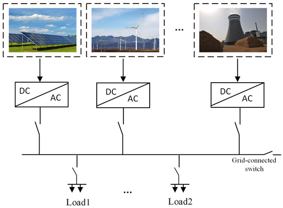
Figure 1.
Microgrid structure diagram.
In the context of microgrids, droop control serves to simulate the droop characteristics of synchronous generators. As a result, it can make adjustments to the voltage and frequency of the inverter output, ensuring that the microgrid can work under different load conditions. Figure 2 illustrates the topology of a typical microgrid. In every , the power supply is linked to the point of common coupling (PCC) via a three-phase voltage source converter. The inductance and capacitance serve the purpose of filtering the output switch noise. Due to the random integration locations of units, the line impedances of different are usually different. The local droop controller is divided into droop control and voltage–current double-loop control. and represent the line impedances between different and the bus. The droop control is used to control the active power and reactive power of each unit, while the voltage–current double-loop control is used to control the output voltage and frequency.
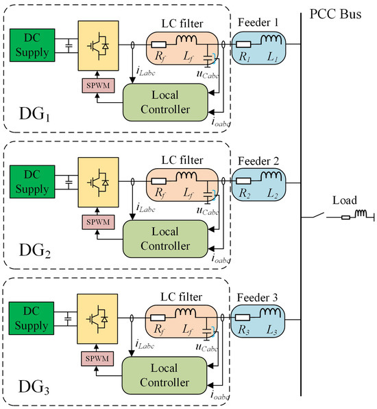
Figure 2.
Structure of an islanded microgrid with three units.
Regarding the control strategy of the voltage–current double-loop: Firstly, through sampling the inverter module, the output voltage and current of the microgrid are obtained. The three-phase electrical voltages and currents are converted to the dq axis via the Park transformation, and then the electrical power is computed. A dual-loop control of voltage and current is realized using the dq-axis elements of the electrical voltages and currents. The resultant power output of the microgrid is ascertained by a power computation unit along with a low-pass filter. The phase angle and voltage magnitude are derived from the active power droop controller and the reactive power droop controller, respectively. The phase angle and magnitude are then synthesized into the reference voltage needed for the voltage–current double-loop control. Because voltage and current fluctuations in the system, as well as changes in load, can produce high-frequency noise and interference, active and reactive power must be calculated after passing through a low-pass filter to eliminate these high-frequency components. This results in a smoother, more stable power value, which is beneficial for improving the stability and reliability of droop control. Finally, the reference voltage values and are adjusted using voltage proportional–integral (PI) control, while and are adjusted using current PI control. This process aims to obtain a controllable sinusoidal modulation signal. The switching signals are then transmitted to the inverter after modulation.
2.1. Traditional Droop Control Approach
The microgrid consists of , loads, and energy storage devices, etc. The units are linked with the common bus by means of power electronics and, subsequently, are connected with the common grid via static switches, and the switching of the microgrid to the off-grid operation mode can be realized through the opening and closing of those static switches. When the switch is disconnected, the microgrid transitions to the islanded operation mode, and the units provide energy to the loads in the entire system. When the microgrid operates in an islanded mode, the electrical energy needed by the consumers has to be supplied via the inverter through the feeder. Since the capacity of a single unit is limited, multiple are generally chosen to operate in parallel to increase the total capacity of the microgrid system. For the convenience of analyzing the control scheme of droop, the local load of the units is ignored and the system is simplified to a parallel-connected configuration of two inverters. The corresponding equivalent model is presented in Figure 3.
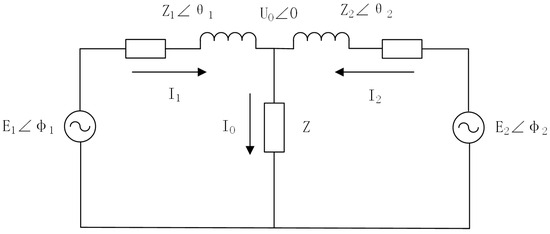
Figure 3.
Equivalent circuit diagram of two inverters connected in parallel.
and are the output voltages at the inverter side, and are the line impedances from the output of the inverter to the common terminal, and are the phase angles between the output voltage of the inverter and the output voltage of the common terminal, and are the line impedance angles, Z is the load impedance, is the output voltage of the common terminal, is the load current, and and are the output currents of the inverter power supply, where and are denoted as:
The real power of a decentralized power source i (i = 1, 2) is denoted by and the reactive power is denoted by :
The line impedance is usually very small in conventional droop control, i.e., the angle formed by the inverter output voltage E and the load voltage is very small, so = 0, and there is: sin = and cos = .
To enhance the quality of the grid-side current, an LC filter circuit is typically attached to the inverter’s output to reduce harmonic content. After the system incorporates the filter circuit, the impedance of the distributed power supply line is inductive [26,27]. At this moment, the inductive part of the circuit impedance is significantly greater than the resistive part, so the resistive part is neglected. And now, = /2. As a result, the active and reactive power of the can be simplified to:
From (5) and (6), it can be seen that whether the active power P of the unit can be equalized is determined by the voltage phase angle, while the voltage magnitude determines whether the reactive power Q can be equalized. Since = d/dt, the phase angle difference can be adjusted by controlling the angular velocity; the and droop control equations for an islanded microgrid system dominated by inductive line impedance are:
Here, and represent the output voltage angular frequency and amplitude of the unit under no-load conditions, respectively, while m and n are the droop coefficient values for the active and reactive power output from the , respectively. The control schematic diagram of droop control can be obtained through (7) and (8), as shown in Figure 4.
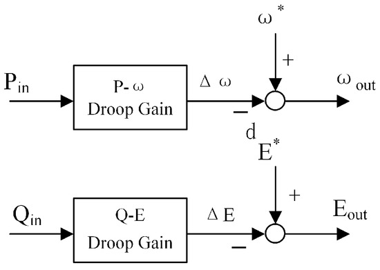
Figure 4.
Schematic diagram of traditional droop control.
From Figure 4 and the droop equation, we can obtain the droop characteristic curve and droop characteristic curve as shown in Figure 5.
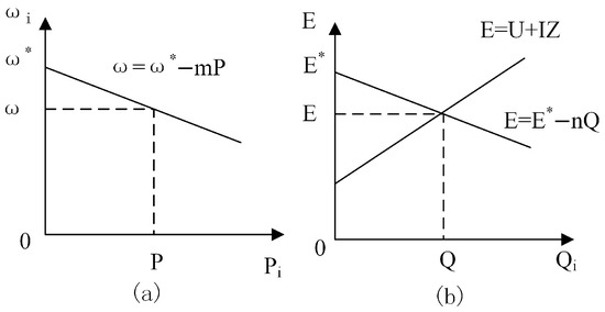
Figure 5.
(a) droop characteristic curve (b) droop characteristic curve.
The droop characteristic curve provides a very intuitive description of the mathematical relationship between the frequency and active power output of the inverter, as well as the output voltage and reactive power. When the active power of the load increases, the active droop curve control reduces the system frequency, and the active power output of the inverter increases, thus satisfying the power balance of the system. Conversely, when the active power of the load decreases, the droop control will cause the system frequency to increase, which in turn reduces the active power output, and the system reaches a new steady-state operating point. The reactive power regulation process of the load is similar to that of active power, but the reactive power output of the inverter can be regulated by the output voltage reference, so the change in reactive power is also related to the voltage drop across the corresponding line impedance.
2.2. Power Sharing Analysis
From the two Equations (5) and (6), as can be observed, the line output impedance is of an inductive nature. The output active power of the unit is associated with the voltage frequency, and the output reactive power is related to the voltage amplitude. When the parallel system reaches a steady state, all the units must operate at the same frequency (50 Hz), i.e., all the units must have equal operating frequencies, taking two units as an example: = , otherwise the system will be unstable. This ensures that the inverter output active power can be precisely distributed in a microgrid system where the output impedance is inductive. At this point, it is only necessary to set the active droop coefficient of the units and the rated power to satisfy the following relationship
This enables the equal distribution of active power output among inverters.
The reactive power in the microgrid setup is achieved through reactive-voltage droop regulation. To make the reactive power output from every module uniform, then, similar to the active power situation, the reactive droop factor is in inverse proportion to
From Equations (6) and (8), the output reactive power of each inverter is given as
which is the equivalent line impedance for every inverter, and the output voltage from each. The inconsistency in the line impedance of each unit leads to inconsistency in the final output voltage at the bus connection point. Since voltage is a localized variable, it is not the same between each parallel inverter, i.e., there exists a voltage offset. As electrical potential and reactive electrical power are interrelated, the presence of voltage offset indicates that reactive electrical power cannot be well equalized and balanced between each inverter. The inability to effectively equalize reactive power in a distributed generation parallel system not only reduces the operating efficiency of the entire microgrid but can also seriously damage the operation of the microgrid.
Under traditional droop regulation, the issue of reactive power equalization imbalance can be addressed through adjusting the reactive power droop factor. Taking two parallel-connected as an example, the graph of the reactive power droop is presented in Figure 6.
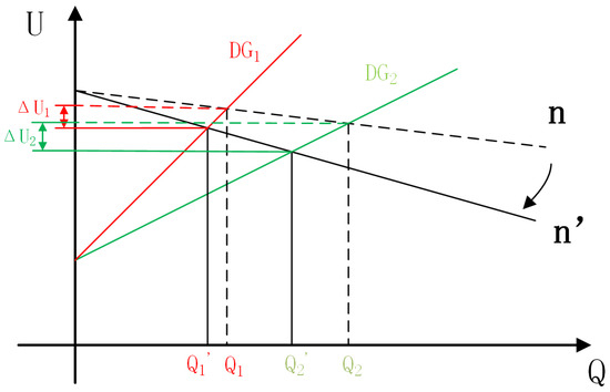
Figure 6.
Reactive power droop coefficient diagram.
In the figure, and represent the reactive power of the two when the system is working at the reactive droop coefficient of n. and represent the reactive power when the reactive droop coefficient is increased from n to . From the figure, it can be concluded that , i.e., when increasing the reactive droop coefficient, it can reduce the difference between the reactive powers of , which is a certain improvement in the problem of reactive power imbalance in the traditional droop control. Additionally, when the reactive power droop coefficient is increased from n to , there are different degrees of voltage drops and in both and . By increasing the reactive power droop coefficient, a significant voltage drop is introduced, which affects the stability of the system. Therefore, the conventional droop control needs to solve two major problems: the unbalanced reactive power equalization problem and the voltage drop problem caused by droop control.
3. Control Strategies for Adaptive Droop Coefficients
The unequal line impedance leads to the unequal output voltage of , so that the reactive power is equalized equally between , and the voltage difference between is
From Equations (6), (8), and (12), can be rewritten as
From Equation (13), we can know that to eliminate the non-uniform allocation of reactive power resulting from line impedance disparity, the following relationship must be satisfied:
When the correlation between line impedance X and reactive power droop coefficient fails to meet the relationship in (14), the system’s reactive equalization cannot be balanced. Generally the line impedance in the microgrid remains unchanged; therefore, it is considered that varying the reactive droop coefficient n to satisfy Equation (14) can achieve reactive power equalization.
3.1. Adaptive Droop Coefficients Based on Improved Consistency Algorithms
“Coherence” refers to the gradual migration of all nodes in the system towards a consistent state to achieve a certain control goal as time progresses. The advantage of the coherence algorithm is that the intelligent individuals in the system only need to exchange information with their neighboring nodes. After this, the neighboring nodes then exchange information with their neighboring intelligent nodes, ultimately achieving coherence and coordination, and ensuring overall coherence and consistency. This method does not require obtaining the information of all intelligent body nodes globally, as in centralized control, and the control protocol should satisfy the following equation.
The reactive electrical power droop regulation is enhanced based on the consistency algorithm:
Droop control leads to a certain degree of voltage drop, which varies among due to line impedance mismatch, so the voltage difference between is employed to adjust the reactive power.
where e represents the potential difference across the two and c denotes the regulation gain; this value is positive. and are the proportional and integral coefficients within the PI regulator, respectively. The whole control process is shown in Figure 7. The voltage difference is fed back to the proportional–integral controller through the auxiliary control to obtain the reactive droop coefficient compensation term. Before the reactive electrical power equalization, the potential difference between the is not 0. This difference will regulate , so that changes with the voltage difference, and the value of also regulates the output voltage E value of the , making the output voltages of the two gradually approach each other, so that the difference of the voltages between the tends to be 0, i.e., in the formula in (12) tends to be 0 until the relationship in (14) is satisfied, and the reactive power equalization is realized.
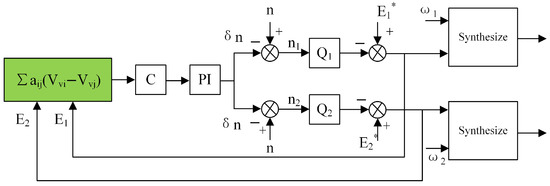
Figure 7.
Control block diagram of adaptive reactive power droop coefficient.
To clearly demonstrate the process of achieving the reactive component of power sharing through the dynamic adjustment of the adaptive droop coefficient, we take and as examples for illustration: When the reactive component of the power output of is relatively high, it is possible for it to be inferred from Equation (8) that its output voltage is small. At this time, the voltage difference between and other (here, is taken as an example) is negative. Based on this result, according to the corresponding control logic, the droop compensation term is positive. Then, according to Equation (16), when the droop compensation term is positive, the reference voltage of will decrease. The decrease in the reference voltage , combined with the relationship described in Equation (6), will cause the reactive component of the power output of to decrease accordingly. Similarly, the reactive component of the power output of increases. Through such a dynamic adjustment mechanism, the adaptive droop coefficient can effectively regulate the reactive power output of each , and ultimately achieve reactive power sharing between and , ensuring the rationality and stability of the reactive component of power distribution in the microgrid.
3.2. Voltage Secondary Compensation Strategy
In a microgrid that adopts the traditional droop control strategy, when there is a load power fluctuation, the inverter output voltage will exhibit a significant deviation. As shown in Figure 6, when the method of adjusting the reactive component of the power droop coefficient is used to address the microgrid reactive component of power imbalance problem, a voltage drop occurs. In order to guarantee the voltage quality and the accuracy of the sharing of real and imaginary powers, the implementation of secondary-level voltage compensation is necessary. This ensures the stability in the voltage output and the reasonable allocation of reactive power. When the system voltage experiences a reduction due to adaptive droop factor adjustment or an increase in load reactive power, the voltage reduction is brought back to the rated value via secondary-stage voltage regulation control. As depicted in Figure 8, a feedback loop is introduced to achieve compensation for the output voltage amplitude of the inverter, enhancing the adaptability and stability of the system.
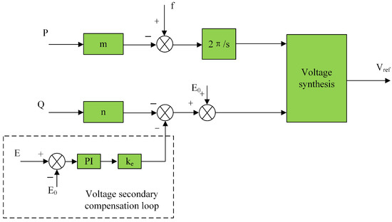
Figure 8.
Block diagram of voltage secondary compensation control.
Based on the voltage control strategy as shown in Figure 8, the expression for the voltage secondary compensation can be summarized as
where is the adaptive droop coefficient output in Figure 7, the voltage difference is used as the feedback signal, and the adaptive droop coefficient is compensated by the PI controller. Here, denotes the reference voltage magnitude, and represents the voltage magnitude output from the droop controller in Figure 6 after the adaptive droop coefficient has been improved. The voltage amplitude links and combines the adaptive droop coefficient with the voltage secondary compensation, and the voltage amplitude output by the reactive droop regulation of the adaptive droop coefficient participates in both the voltage synthesis and the voltage secondary compensation control. The parameters and are the proportional and integral coefficients of the PI control, respectively, which are used to compensate for the influence of the output voltage variation of the shunt inverter in the microgrid. Additionally, is the correction coefficient, which primarily aims to amplify the feedback part of the voltage compensation. The purpose of this method is to make an adaptive adjustment of the droop coefficients for the purpose of achieving non-active power equalization. Moreover, this method does not require knowledge of the circuit line impedance, nor does it cause a voltage drop, and it does not necessitate the measurement of additional information. As a result, it enhances the flexibility and reliability of the controller.
3.3. System Stability Analysis
The root locus represents the path traced by the solutions of the closed-loop system in the complex plane as a specific parameter of the system varies across a defined range according to the dynamic characteristic equation of the system. The steadiness of a feedback-controlled system is fundamentally determined by the positions of the roots of its characteristic equation. Consequently, the root locus offers an intuitive visualization of how the system’s stability evolves with parameter variations. This approach stands out for its simplicity in model construction and ease of comprehension. It serves as a valuable guide for engineers and designers, offering clear-cut directions in the process of fine-tuning system parameters to ensure that the system meets the desired performance criteria.
First, the filtering inductor is discussed. Usually, the potential difference across the filtering inductor is required to be within 5% of the rated voltage, as shown in Equation (20). From this, the upper bound of the inductance value can be determined.
The maximum allowable ripple of the inductor current is of the output current amplitude. Therefore, the lower bound of L is shown in Equation (21).
According to Equations (20) and (21), the range of the filtering inductor L can be obtained, which is approximately from 1.5 mH to 4.6 mH. When other system parameters remain unchanged and the filtering inductor varies within the above-mentioned range, the root locus of the filtering inductor L is plotted in MATLAB R2021b, as shown in Figure 9.
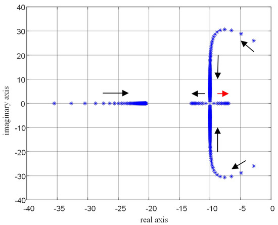
Figure 9.
Root locus variation of the filtering inductor L.
In the system analysis, it can be observed that as the value of inductance L gradually increases, the imaginary parts of the conjugate imaginary roots will gradually approach zero. This change significantly enhances the system’s damping effect, effectively suppressing the oscillations within the system and improving the system’s stability and anti-interference ability. However, a larger value of inductance L is not always better. When the value of inductance L is either too large or too small, some roots will gradually approach the right-hand side of the real axis. In automatic control theory, roots located on the right-hand side of the real axis indicate the presence of unstable factors in the system, which will cause the system response to diverge and seriously affect the normal operation of the system. Based on the above analysis, to ensure that the system has both a good damping effect and high stability, a trade-off is required when selecting the value of inductance L. After comprehensive consideration and experimental verification, a strategy of choosing a middle-range value is adopted, and finally, the filtering inductance L is determined to be 3 mH.
Generally, the reactive current allowed to pass through the filtering capacitor should not exceed 5– of the rated current value. The calculated capacitance value ranges from 16.4 μF to 31.8 μF. Similarly, the root locus diagram regarding the filtering capacitance value is drawn as shown in Figure 10.
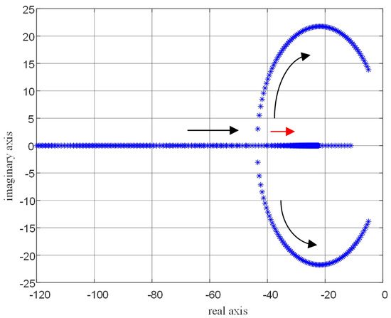
Figure 10.
Root locus variation of the filtering capacitor C.
Similar to the root locus diagram of the filtering inductor, when the value of capacitor C is either too large or too small, the roots will gradually move towards the right-hand side of the real axis. This implies that there may be instability factors in the system, which can affect the system’s stability. Therefore, a strategy of choosing a middle-range value is also adopted. Finally, the value of the filtering capacitor C is determined to be 20 μF to ensure that the system has good stability and performance.
The setting of the control gain c is a relatively complex issue. The core consideration in the course of the setting process is to guarantee the stability for the system and enable the adaptive droop coefficient to exhibit good performance.Precisely adjusting the control gain can significantly enhance the PI controller’s ability to regulate system errors. This not only greatly improves the control accuracy of the adaptive droop coefficient, ensuring that it can more accurately follow the dynamic changes of the system, but also further enhances the accuracy of the sharing of reactive power, making the operation of the entire system more stable and efficient. To conduct an in-depth study on the impact of the control gain c on the system, let the control gain c vary within the range of 0 to 1, and draw the corresponding root locus diagram. This allows for an intuitive analysis of how the characteristic roots of the system change with the system gain c, thereby providing a basis for the reasonable setting of the control gain c, as shown in Figure 11.
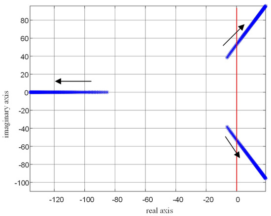
Figure 11.
Root locus plot of the control gain c varying from 0 to 1.
It can be clearly observed from the root locus diagram that as the control gain c continuously increases, characteristic roots appear in the right-hand side of the real axis. When the characteristic roots of the system appear in the right-hand side of the real axis, the system will lose stability. This fully indicates that the control gain c should not be set too large. In order to determine the value of the control gain c that can not only ensure the stable operation of the system but also enable the controller to achieve good results, after repeated attempts in the simulation, the value of the control gain c is finally determined to be 0.1.
For , t is crucial so that the inverter can stably output a high-quality alternating current. In this process, the reasonable design of proportional–integral controller coefficients during the control process that combines the voltage loop and current loop plays a vital role.
First, regarding the design of proportional–integral controller coefficients within the single loop-based control, Figure 12 shows the Bode diagram of the internal loop-based control.
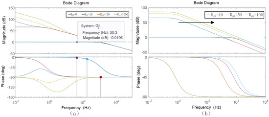
Figure 12.
Bode diagram of the current inner loop. (a) Integral coefficient variation diagram. (b) Proportional coefficient variation diagram.
Figure 12a shows the chart depicting the current inner loop control corresponding to the change in the integral coefficient while the proportional coefficient remains constant. After in-depth analysis of the chart, it is found that the change in the integral coefficient has no significant impact on the system stability. It is obvious that from the graph, the amplitude–frequency response curves of the closed-loop transfer function almost completely overlap, which means that the adjustment of the integral coefficient also has little effect on the system performance. In view of the simplification principle that should be followed in system design, after comprehensive consideration, it is finally decided to set the integral coefficient to 100 in the current outer-loop control. Figure 12b presents the plot representing the current inner-loop control corresponding to the gradual increase in proportional coefficient while the integral coefficient remains constant. It can be observed from the Bode diagram that as the proportional coefficient gradually increases, the magnitude–frequency curve representing the transfer function continuously shifts to the right. Since the cut-off frequency exerts an important effect on system performance, a suitable value needs to be selected. After comprehensively considering various factors, the current’s proportional coefficient of the outer-loop is finally determined to be 50.
After the proportional–integral parameters for the current inner loop are accurately determined, the next step is to consider optimizing the settings of the voltage outer-loop so as to guarantee that the system can achieve better operating results. Figure 13 shows the Bode diagram corresponding to the values of the optimized voltage external-loop control. This diagram provides a visual basis for analyzing the dynamic characteristics and stability of the external-loop voltage regulation under the action of the optimized parameters.
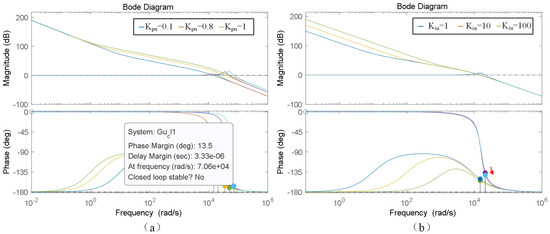
Figure 13.
Bode diagram of the voltage outer-loop control. (a) Proportional coefficient variation diagram. (b) Integral coefficient variation diagram.
Figure 13a shows the Bode diagram obtained by changing the proportional coefficient while keeping the integration coefficient related to the voltage of the outer loop constant. As the proportional parameter continuously increases, the stability margin of the system shows a continuous downward trend. Meanwhile, a relatively slight resonance phenomenon occurs, which has an adverse effect on the system stability. Considering the importance of the stability margin and resonance phenomenon in order to maintain the system’s stable operation, the proportional coefficient of the voltage outer loop should not be too large. After comprehensively considering the system’s stability requirements and various performance indicators, the value of the proportional gain of the voltage outer loop is finally determined to be 0.8. Figure 13b shows the Bode diagram obtained by changing the integral coefficient while keeping the proportional factor of the voltage of the outer loop constant. As the integral gain gradually increases, the stability margin for the system will slightly decrease. When the integral gain is too small, the tracking performance belonging to the system of the phase–frequency behavior will significantly deteriorate. The stability margin is related to the stability and dependability of system functioning, and the tracking performance of the phase–frequency response directly affects the system’s capacity to track and respond to input signals. Both are crucial for the comprehensive performance of the system. Therefore, it is necessary to make a trade-off between the stability margin and the tracking performance of the phase–frequency response. After comprehensively comparing the performance of the system under different integral coefficients, the integral coefficient is finally selected as 20 to achieve a relatively ideal balance between the stability margin and the tracking performance of the phase–frequency response.
4. Verification via Simulation
To substantiate the effectiveness of the advanced control approach presented in this paper, a simulation model for two inverters was built on the MATLAB/Simulink platform. This model was designed based on the configurations shown in Figure 7 and Figure 8, with the aim of investigating and deliberately examining the issue of reactive power allocation in parallel connections. The related simulation parameters are detailed in the Table 1. The model comprehensively incorporates the two critical factors—the capacity and line impedance.
To simplify the situation, the normalized reactive power error is utilized.


Table 1.
Simulation model system parameters.
Table 1.
Simulation model system parameters.
| Parameters | Values | Parameters | Values |
|---|---|---|---|
| DC link voltage | 800 V | Load 2 (W,) | 5000 + j5000 |
| Switching frequency | 20 kHZ | Active droop coefficient | 0.000314 |
| Filter inductance | 3 mH | Reactive droop coefficient | 0.000622 |
| Filter capacitor | 20 μF | Control gain c | 0.1 |
| Filter resistance | 0.2 | Voltage compensation coefficient | 0.14 |
| Nominal frequency | 50 Hz | Low-Pass filter | 50 Hz |
| Noninai line to line RMS voltage | 380 V | 0.1 | |
| ’s Line impedance | 0.7 + j0.007 | 10 | |
| ’s Line impedance | 0.5 + j0.0065 | 0.8 | |
| Load 1 (W,) | 10,000 + j10,000 | 20 |
4.1. Performance with Conventional Controller
Figure 14 shows the power sharing situation under traditional droop control when two (Distributed Generators) have the same power rating. In Stage 1 (0 < t < 2 s), the microgrid initially operates with Load 1. At t = 2 s, Load 2 is connected to the grid, which not only causes a change in the load but also alters the structure of the microgrid to some extent. Load 2 is disconnected at t = 2.5 s.
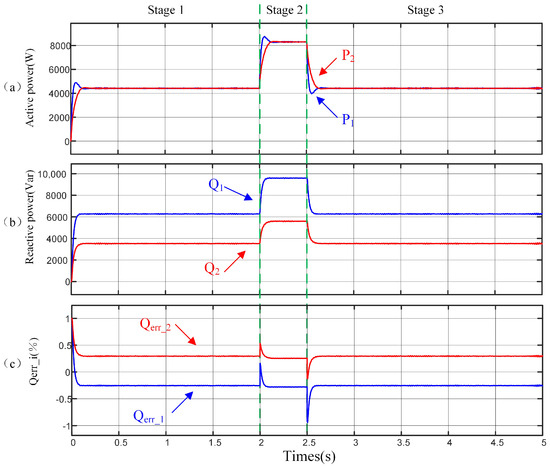
Figure 14.
A simulation of the power sharing performance using the conventional droop control is carried out. (a) Active power. (b) Reactive power. (c) (%).
In the steady state, the reactive power sharing shown in Figure 14b exhibits poor performance, whereas Figure 14a shows accurate active power sharing. In Figure 14c, during the first stage, the reactive power sharing error of both and is 34%. However, when Load 2 is added at t = 2 s, the reactive power sharing errors of both and rise to 36%,which indicates that the structure of the microgrid has a certain impact on the power sharing performance. As shown in Figure 14, the traditional droop controller cannot achieve an equal sharing of reactive power.
The power sharing performance of the control scheme developed in [28], which is one of the most effective decentralized control schemes adopting adaptive virtual impedance, is presented in Figure 15. The same operations as those in Figure 14 are carried out. At t = 2 s and 2.5 s, the changes in the load conditions are the same as those in Figure 14. As shown in Figure 15, the method in [28] can achieve more accurate power sharing of reactive power under any load conditions, with the reactive power sharing error being 18%. When contrasted with the traditional droop control, the performance of reactive power sharing is enhanced.
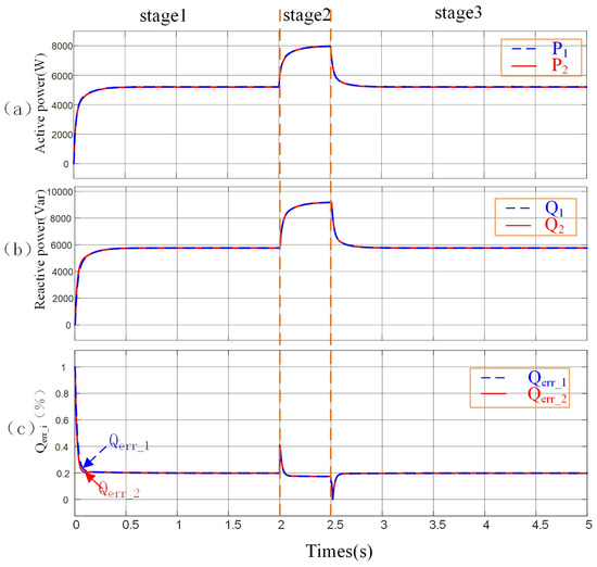
Figure 15.
A simulation was conducted on the performance of the decentralized control scheme having the same power ratings. (a) Active power. (b) Reactive power. (c) (%).
4.2. Performance When Using the Proposed Controller
Figure 16 shows the performance of the proposed control method when the units have the same rated power. Under the same conditions as in Figure 14, the operating and load conditions change. It can be seen that under any load conditions and microgrid configurations, this method ensures the accurate sharing of both active power and reactive power. As clearly shown in Figure 16c, in the steady state, is only 8%, and the accuracy of reactive power sharing of this method is significantly improved. Figure 17 shows the changes in the adaptive reactive power droop coefficients of two units. After applying the proposed method, the reactive power droop coefficients of the are adaptively adjusted to achieve an average sharing of reactive power.
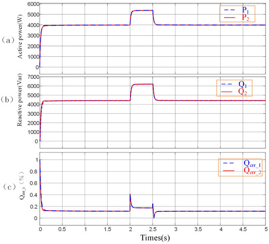
Figure 16.
A simulation of the performance of the proposed controller under the condition of the same power ratings was carried out. (a) Active power. (b) Reactive power. (c) (%).
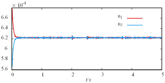
Figure 17.
The change in the droop coefficient.
Figure 18 demonstrates the performance of the proposed control method when the distributed generation () units have different rated powers. Even when there are differences in the rated powers of the units, this method still enables the units to accurately achieve equal sharing of both active power and reactive power. This fully indicates that the proposed method has strong adaptability and can significantly improve the accuracy of power sharing under various operating environments and working conditions.
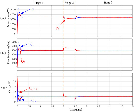
Figure 18.
A simulation was carried out on the performance of the proposed controller with varying power ratings. (a) Active power. (b) Reactive power. (c) (%).
To more clearly compare the dynamic process of reactive power sharing, we extracted the data from the first 0.5 s of the reactive power sharing graphs in Figure 15b and Figure 16b and compiled them into Figure 19. Among them, Figure 19a shows the reactive power sharing situation of the method proposed in this paper. It can be clearly seen from the figure that this method can excellently achieve the equal sharing of reactive power within just 0.1 s, enabling the system to quickly reach a steady state. The entire parallel-connection process is smooth and stable. On the contrary, Figure 19b presents the reactive power sharing effect of the method proposed in Reference [28]. Under this method, the system takes 0.5 s to finally achieve power sharing and reach a steady state. Comparing the two methods, the method proposed in this paper has significant advantages in the parallel-connection effect. It is 0.4 s faster than the method in Reference [28], and the speed-up amplitude reaches as high as 80%. This remarkable improvement fully demonstrates the high efficiency of the proposed method and greatly enhances the system’s response efficiency.
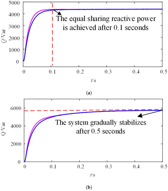
Figure 19.
Comparison of response speed between adaptive virtual inductance method and adaptive droop coefficient method. (a) Adaptive droop coefficient method. (b) Adaptive virtual inductance method.
4.3. The Voltage Compensation Performance of the Proposed Method
Figure 20 intuitively presents a comparison of the differences in the compensation effects of the output voltage amplitude between the traditional droop control strategy and the proposed secondary voltage compensation strategy. Among them, Figure 20b further focuses on demonstrating the compensation effect of the proposed strategy on the output voltage amplitude. When the proposed secondary voltage compensation strategy is adopted, the output voltage amplitude of the can be automatically and precisely adjusted to the reference voltage amplitude of 311 V. Figure 20a shows the output voltage amplitude under the traditional droop control method. It can be clearly seen that the voltage drop caused by the traditional droop control is very significant, and the output voltage amplitude cannot recover on its own. In contrast, after the system reaches a steady state using the proposed method, the output voltage amplitude can almost return to 311 V, which fully proves the effectiveness of this method. This method greatly improves the stability of the system. When Load 2 is connected at time t = 2 s, the proposed method demonstrates excellent adaptability and can adjust the output amplitude adaptively. This performance further and powerfully indicates that the method has strong anti-interference ability.
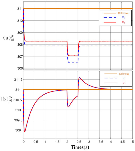
Figure 20.
Output voltage amplitude. (a) Traditional droop control. (b) The proposed method.
Through a comparative analysis of the simulation results of three control methods, namely the traditional droop control, the improved droop control using the adaptive virtual impedance method, and the adaptive droop coefficient method proposed in this paper, the following conclusions can be drawn: Under inductive line loading conditions, improved droop control can effectively equalize the reactive power distribution among . However, even the most effective adaptive virtual impedance method demonstrates relatively weaker system regulation ability under increasing system loading or when encountering perturbations, and the time required to reach a new steady state is notably longer.
The method proposed in this paper can effectively compensate for the problem of line impedance mismatch and quickly achieve accurate reactive power distribution in the microgrid. In this method, the parameters for adjusting the droop coefficient only utilize the reactive power of and can be adaptively adjusted, which improves the accuracy of reactive power sharing. Even if the microgrid configuration or load changes during the adjustment process, more accurate reactive power distribution can still be achieved. The proposed scheme proves to be extremely useful for ensuring the effective operation of in a stand-alone microgrid.
4.4. Power Sharing of Three Distributed Generators
To further verify the practicality and scalability of the proposed scheme, we extended the system from two parallel-connected to three parallel-connected . The power sharing effect is shown in Figure 21. It can be clearly observed from the figure that, whether it is active power or reactive power, the output curves of the three inverters almost completely overlap. This result fully demonstrates that this method is not only applicable to microgrids with two parallel but also can still exhibit excellent performance when applied to microgrids with more than two , effectively achieving precise power sharing.
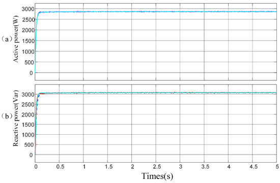
Figure 21.
Power sharing of three distributed generators. (a) Active power. (b) Reactive power.
It can be observed from the simulation results that the method proposed in this paper does not require knowledge of the specific value of line impedance. It can solve the problems of voltage deviation and reactive power equalization with high precision and a fast response speed, and effectively achieve equal distribution of reactive power.
In this paper, the advantages and disadvantages of the proposed method, traditional methods, virtual impedance methods, and adaptive virtual impedance methods are systematically summarized, and the results are presented in Table 2.

Table 2.
Method comparison.
When the circuit impedance exhibits inductive characteristics, the traditional droop control method shows obvious limitations. Due to the non-uniformity of the line impedance distribution, it is difficult to achieve equal sharing of the reactive power output by . This leads to some bearing excessive reactive power while others have insufficient reactive power output, which affects the operating efficiency and stability of the entire system. However, the principle and implementation of traditional droop control are relatively simple, with fewer control parameters and a simple controller structure, making it easy to implement.The adaptive virtual impedance method can automatically adjust its value according to the real-time operating state of the system and the reactive power distribution, thus achieving precise equal sharing of reactive power among . Nevertheless, its response speed is slow, requiring a large amount of calculation and complex algorithm processing, which limits its application in scenarios with high requirements for response speed to a certain extent.
The method proposed in this paper achieves remarkable results in reactive power sharing. The speed of reactive power sharing has been significantly increased, reducing from the traditional 0.5 s to 0.1 s, a speed-up rate of , which greatly improves the system response efficiency. The reactive power sharing error is only 8%. This method has a better ability to share reactive power evenly, enabling efficient and precise equal distribution of reactive power. Meanwhile, it performs excellently in key performance indicators such as response speed, stability, and anti-interference ability. It responds more rapidly, the system operates more stably, and it has a stronger ability to resist external interference.
5. Conclusions
In the current research, after conducting an in-depth analysis of the reactive power sharing errors and the deficiencies of fixed droop coefficients, we proposed an improved droop control scheme with an adaptive droop coefficient. This scheme aims to effectively address the issue of line impedance mismatch. On this basis, a secondary voltage compensation scheme is further integrated, which can effectively cope with the adverse effects of the output voltage amplitude drop on the circuit. Compared with traditional control methods, this improved scheme demonstrates significant advantages. During the transient process, it can significantly reduce power oscillation and greatly improve the accuracy of reactive power sharing. Notably, even if the structure of the microgrid changes or the load conditions fluctuate during the adjustment process, the scheme can still achieve accurate reactive power sharing. To comprehensively verify the practicality and scalability of this method, we conducted a verification on the scenario of three operating in parallel. The results show that the system can excellently achieve uniform power sharing. This fully indicates that the proposed control scheme has extremely high practical value for the efficient and stable operation of distributed generators in an islanded microgrid. Meanwhile, the secondary voltage compensation strategy performs excellently. It can precisely track the reference voltage amplitude, effectively eliminate the voltage drop effect caused by droop control, and ensure the power supply quality of the microgrid.
Outlook for future work: (1) Currently, machine learning algorithms, as cutting-edge research methods, have broad application prospects. In the future, it is planned to use machine learning methods to address the existing deficiencies in droop control. Specifically, machine learning algorithms will be employed to determine an appropriate reactive power reference value, and then the virtual impedance will be adjusted based on this reference value to effectively solve the problem of uneven reactive power distribution. (2) In existing droop control research, improvements to the droop coefficient mainly focus on vertically shifting the droop curve or changing its slope. In the future, we consider starting from changing the shape of the droop curve. For example, the hyperbolic tangent (TANH) function can be used to transform the linear droop curve into a curved one, thereby reducing the impact of the droop curve on voltage deviation.
Author Contributions
All authors contributed to the study conception and design. Material preparation, data collection, and analysis were performed by M.W., C.W. and L.W. The first draft of the manuscript was written by C.W. and all authors commented on previous versions of the manuscript. All authors have read and agreed to the published version of the manuscript.
Funding
This study was funded by the Natural Science Foundation of Hubei Province (No. 2022CFA007); the Science and Technology Project of Hubei Province (No. 2022BEC017); Hubei Provincial Department of Education Science and Technology Research Project (No. D20231405); and Wuhan Knowledge Innovation Special Project (No. 2023010201020372).
Data Availability Statement
Data are contained within the article.
Conflicts of Interest
The authors declare no conflicts of interest.
References
- Meng, X.; Liu, J.; Liu, Z. A generalized droop control for grid supporting inverter based on comparison between traditional droop control and virtual synchronous generator control. IEEE Trans. Power Electron. 2019, 34, 5416–5438. [Google Scholar] [CrossRef]
- Tan, K.H.; Tseng, T.Y. Seamless switching and grid reconnection of microgrid using Petri recurrent wavelet fuzzy neural network. IEEE Trans. Power Electron. 2021, 36, 11847–11861. [Google Scholar] [CrossRef]
- Lin, F.-J.; Tan, K.-H.; Chang, C.-F.; Li, M.-Y.; Tseng, T.-Y. Development of intelligent controlled microgrid for power sharing and load shedding. IEEE Trans. Power Electron. 2022, 37, 7928–7940. [Google Scholar] [CrossRef]
- Liu, B.; Wu, T.; Liu, Z.; Liu, J. A small-AC-signal injection based decentralized secondary frequency control for droop-controlled islanded microgrids. IEEE Trans. Power Electron. 2020, 35, 11634–11651. [Google Scholar] [CrossRef]
- Tan, K.-H.; Li, M.-Y.; Weng, X.-Y. Droop controlled microgrid with DSTATCOM for reactive power compensation and power quality improvement. IEEE Access 2022, 10, 121602–121614. [Google Scholar] [CrossRef]
- Guerrero, J.M.; Chandorkar, M.; Lee, T.-L.; Loh, P.C. Advanced control architectures for intelligent microgrids—Part I: Decentralized and hierarchical control. IEEE Trans. Smart Grid 2016, 7, 695–705. [Google Scholar] [CrossRef]
- Fan, B.; Li, Q.; Wang, W.; Yao, G.; Ma, H.; Zeng, X.; Guerrero, J.M. A novel droop control strategy of reactive power sharing based on adaptive virtual impedance in microgrids. EEE Trans. Ind. Electron. 2022, 69, 11335–11347. [Google Scholar] [CrossRef]
- Shi, Z.; Li, J.; Nurdin, H.I.; Fletcher, J.E. Comparison of virtual oscillator and droop controlled islanded three-phase microgrids. IEEE Trans. Energy Convers. 2019, 34, 1769–1780. [Google Scholar] [CrossRef]
- Li, Z.; Chan, K.W.; Hu, J.; Guerrero, J.M. Adaptive droop control using adaptive virtual impedance for microgrids with variable PV outputs and load demands. IEEE Trans. Ind. Electron. 2021, 68, 9630–9640. [Google Scholar] [CrossRef]
- Alghamdi, B.; Cañizares, C.A. Frequency regulation in isolated microgrids through optimal droop gain and voltage control. IEEE Trans. Smart Grid 2021, 12, 988–998. [Google Scholar] [CrossRef]
- Zhang, W.; Wang, W.; Liu, H.; Xu, D. A disturbance rejection control strategy for droop-controlled inverter based on super-twisting algorithm. IEEE Access 2019, 7, 27037–27046. [Google Scholar] [CrossRef]
- Ling, Y.; Li, Y.; Xiang, J. Load support by droop-controlled distributed generations. IEEE Trans. Ind. Electron. 2021, 68, 8345–8355. [Google Scholar] [CrossRef]
- Ling, Y.; Li, Y.; Yang, Z.; Xiang, J. A dispatchable droop control method for distributed generators in islanded AC microgrids. IEEE Trans. Ind. Electron. 2021, 68, 8356–8366. [Google Scholar] [CrossRef]
- Han, H.; Liu, Y.; Sun, Y.; Su, M.; Guerrero, J.M. An improved droop control strategy for reactive power sharing in islanded microgrid. IEEE Trans. Power Electron. 2015, 30, 3133–3141. [Google Scholar] [CrossRef]
- Prakash, S.; Nougain, V.; Mishra, S. Adaptive droop-based control for active power sharing in autonomous microgrid for improved transient performance. IEEE J. Emerg. Sel. Top. Power Electron. 2020, 9, 3010–3018. [Google Scholar] [CrossRef]
- Minetti, M.; Rosini, A.; Denegri, G.B.; Bonfiglio, A.; Procopio, R. An advanced droop control strategy for reactive power assessment in islanded microgrids. IEEE Trans. Power Syst. 2021, 37, 3014–3025. [Google Scholar] [CrossRef]
- Xu, H.; Zhang, X.; Liu, F.; Shi, R.; Yu, C.; Cao, R. A reactive power sharing strategy of VSG based on virtual capacitor algorithm. IEEE Trans. Ind. Electron. 2017, 64, 7520–7531. [Google Scholar] [CrossRef]
- D’Arco, S.; Suul, J.A. Equivalence of virtual synchronous machines and frequency-droops for converter-based microgrids. IEEE Trans. Smart Grid 2014, 5, 394–395. [Google Scholar] [CrossRef]
- Liu, J.; Miura, Y.; Ise, T. Comparison of dynamic characteristics between virtual synchronous generator and droop control in inverter-based distributed generators. IEEE Trans. Power Electron. 2016, 31, 3600–3611. [Google Scholar] [CrossRef]
- Xiong, X.; Wu, C.; Hu, B.; Pan, D.; Blaabjerg, F. Transient damping method for improving the synchronization stability of virtual synchronous generators. IEEE Trans. Power Electron. 2021, 36, 7820–7831. [Google Scholar] [CrossRef]
- Wong, Y.C.C.; Lim, C.S.; Cruden, A.; Rotaru, M.D.; Ray, P.K. A consensus-based adaptive virtual output impedance control scheme for reactive power sharing in radial microgrids. IEEE Trans. Ind. Appl. 2020, 57, 784–794. [Google Scholar] [CrossRef]
- Chen, G.; Guo, Z. Distributed secondary and optimal active power sharing control for islanded microgrids with communication delays. IEEE Trans. Smart Grid 2017, 10, 2002–2014. [Google Scholar] [CrossRef]
- Bidram, A.; Davoudi, A.; Lewis, F.L.; Guerrero, J.M. Distributed cooperative secondary control of microgrids using feedback linearization. IEEE Trans. Power Syst. 2013, 28, 3462–3470. [Google Scholar] [CrossRef]
- Wu, X.; Shen, C.; Iravani, R. A distributed, cooperative frequency and voltage control for microgrids. IEEE Trans. Smart Grid 2016, 9, 2764–2776. [Google Scholar] [CrossRef]
- Schiffer, J.; Seel, T.; Raisch, J.; Sezi, T. Voltage stability and reactive power sharing in inverter-based microgrids with consensus-based distributed voltage control. IEEE Trans. Control Syst. Technol. 2015, 24, 96–109. [Google Scholar] [CrossRef]
- Guo, F.; Wen, C.; Mao, J.; Song, Y.-D. Distributed secondary voltage and frequency restoration control of droop-controlled inverter-based microgrids. IEEE Trans. Ind. Electron. 2014, 62, 4355–4364. [Google Scholar] [CrossRef]
- Simpson-Porco, J.W.; Shafiee, Q.; Dörfler, F.; Vasquez, J.C.; Guerrero, J.M.; Bullo, F. Secondary frequency and voltage control of islanded microgrids via distributed averaging. IEEE Trans. Ind. Electron. 2015, 62, 7025–7038. [Google Scholar] [CrossRef]
- Lin, F.-J.; Tan, K.-H.; Weng, X.-Y.; Li, Y.-R. An improved droop controlled microgrid using intelligent variable droop coefficient estimation. IEEE J. Emerg. Sel. Top. Power Electron. 2024, 12, 4117–4132. [Google Scholar] [CrossRef]
Disclaimer/Publisher’s Note: The statements, opinions and data contained in all publications are solely those of the individual author(s) and contributor(s) and not of MDPI and/or the editor(s). MDPI and/or the editor(s) disclaim responsibility for any injury to people or property resulting from any ideas, methods, instructions or products referred to in the content. |
© 2025 by the authors. Licensee MDPI, Basel, Switzerland. This article is an open access article distributed under the terms and conditions of the Creative Commons Attribution (CC BY) license (https://creativecommons.org/licenses/by/4.0/).