Article

Modeling and Analysis of Stable Contact States in the Anthropomorphic Robotic Hand with Soft Materials and Rigid Structures

1
Unmanned Vehicle Research Center, China North Vehicle Research Institute, Beijing 100072, China
2
China North Artificial Intelligence & Innovation Research Institute, Beijing 100072, China
3
Collective Intelligence & Collaboration Laboratory, Beijing 100072, China
4
Beijing Institute of Technology, School of Automation, Beijing 100081, China
5
School of Mechanical Engineering, Dalian Jiaotong University, Dalian 116028, China
6
School of Mechanical Engineering, Dalian University of Technology, Dalian 116024, China
*
Author to whom correspondence should be addressed.
Electronics 2024, 13(7), 1319; https://doi.org/10.3390/electronics13071319
Submission received: 2 December 2023 / Revised: 19 January 2024 / Accepted: 25 January 2024 / Published: 1 April 2024
(This article belongs to the Special Issue Perception and Control in Mobile Robots)

Abstract

:
Conducting contact state analysis enhances the stability of object grasping by an anthropomorphic robotic hand. The incorporation of soft materials grants the anthropomorphic robotic hand a compliant nature during interactions with objects, which, in turn, poses challenges for accurate contact state analysis. According to the characteristic of the anthropomorphic robotic hand’s compliant contact, a kinetostatic modeling method based on the pseudo-rigid-body model is proposed. It can realize the mapping between contact force and driving torque. On this basis, the stable contact states of the anthropomorphic robotic hand under the envelope grasping mode are further analyzed, which are used to reasonably plan the contact position of the anthropomorphic robotic hand before grasping an object. Experimental results validate the efficacy of the proposed approach during grasping and ensure stable contact in the initial grasping stage. It significantly contributes to enhancing the reliability of the anthropomorphic robotic hand’s ability to securely grasp objects.

1. Introduction

Grasping is one of the most critical applications in humanoid robotics [1]. For specific grasping tasks, anthropomorphic robotic hands typically initiate contact with the target object by using their fingers to establish grasping constraints before executing a grasping operation [2]. Analyzing the contact states of anthropomorphic robotic hands prior to grasping an object allows for an in-depth planning of finger–object contact positions, thereby preventing potential grasp failures or instabilities. Such contact state analysis enhances the success rate of grasping tasks, enabling anthropomorphic robotic hands to adeptly tackle various grasping challenges with finesse [3].
Currently, research pertaining to the analysis of stable contact states in anthropomorphic robotic hands can be broadly classified into two primary categories [4,5,6,7]. The first category involves direct acquisition of contact state information by incorporating tactile or other sensory mechanisms onto the surface of robotic hands [8,9]. These sensors have the capability to directly measure important parameters, such as contact force [10], contact area [11] and contact duration [12], between the robotic hands and the target objects, providing intricate data regarding the interaction between the fingers and the objects. The second category encompasses indirect estimation of contact states through modeling and analysis of the grasping process. While this approach might not yield data accuracy on par with that of direct sensor measurements, it still offers invaluable insights, especially in scenarios where sensor technology encounters limitations or implementation challenges.
The second category for the analysis of stable contact states in anthropomorphic robotic hands serves as a viable alternative to the first method, offering advantages in enhancing system robustness and improving the cost-effectiveness of real-world applications. Research in this field, focused on stable contact states, primarily encompasses aspects such as identifying instances of contact, estimating contact forces/torques, as well as evaluating contact positions. Firstly, it facilitates the estimation of whether the robotic hand has established contact with its surrounding environment. Lin et al. [13] introduced an innovative gripper that incorporated transparent transmission with low reflective inertia in its fingers, Backus et al. [14] investigated the resonant frequency of the flexible joints in robotic fingers through employing a phase-locked loop. For a soft robotic hand, Homberg et al. [15] developed a bending configuration model to gather contact-related information with objects. Secondly, in the analysis of contact force/torque, Del Sol et al. [16] utilized a force/torque estimation technique within a radioactive environment, where dose rates impose constraints on the utilization of sensory and electronic devices in teleoperated robots. Moreover, Santina et al. [17] combined the flexibility model of the Pisa/IIT hand with geometric configurations. For soft robotic hands, Shan et al. [18] simplified flexible fingers into a multi-beam structure to assess the grasping ability of the FRE gripper, whereas Zhou et al. [19] investigated compliant deformation using smart materials and structures. Thirdly, for determining the contact position, Kaneko et al. [20] proposed an early method based on joint compliance for active perception. Belzile et al. [21] conducted a comprehensive analysis of contact state for a dual tendon finger through meticulous simulations. Pastor et al. [22] addressed the estimation problem of forearm roll angles to ensure the safe operation of human limbs. Similarly, Karayiannidis et al. [23] introduced a model-free position calibration method. For a soft gripper, Park et al. [24] presented an optimal strategy for controlling grasping positions. Furthermore, in the exploration of various contact states, Abdeetedal et al. [25] investigated contact forces and positions between fingers and objects, without compromising the gripper’s size and system complexity. Deckers et al. [26] utilized a partially observable Markov decision process to guide the selection of grasping strategies. In agricultural and food industry applications, Korenblik et al. [27] leveraged current data on displacement and drive from grippers to accurately estimate contact poses, object sizes, and contact forces.
In summary, the aforementioned research methodology not only reduces the cost associated with robotic hands but also simplifies the overall system, rendering it more pragmatic and robust. This is particularly advantageous in environments contaminated by radiation, where strict limitations on sensor usage prevail. Presently, relevant research has predominantly been concentrated on contact analysis for rigid hands. However, there has been a notable lack of attention directed toward soft hands and rigid–soft hybrid hands. Furthermore, the available systematic modeling and analysis approaches in this context are inadequate.
In this paper, we initially introduced the design of a rigid–soft anthropomorphic hand with elastic joints and flexible finger segments. This robotic hand demonstrates excellent adaptability in grasping and dexterous manipulation. Nonetheless, the incorporation of elastic joints and flexible finger segments introduces complexities and challenges when it comes to analyzing stable contact states. Given the distinctive characteristics of the mechanism, exploring a tailored method for the analysis of stable contact states holds significant theoretical and practical importance. It has the potential to significantly enhance the mechanism’s capability to grasp objects with reliability.

2. The Anthropomorphic Robotic Hand with Soft Materials and Rigid Structures

Rigid robotic hands are typically constructed from metal or hard plastic structures, offering limited adaptability to their surroundings. In contrast, soft robotic hands exhibit good compliance but lack the biomimetic and dexterous abilities required for effective object manipulation akin to human hands. To address these challenges and strike a balance between dexterity, adaptability, and system integration, the authors propose an innovative solution: a rigid–soft anthropomorphic robotic hand system [28], depicted in Figure 1. The robotic hand’s modular design enables the thumb with 4 degrees of freedom, facilitating abduction/adduction and flexion/extension movements. The remaining four fingers possess three degrees of freedom for flexion/extension. The robotic hand’s overall size closely emulates that of an adult human hand, weighing approximately 600 g. The electrical and driving systems are seamlessly integrated within the mechanism.
For the fabrication of the rigid–soft robotic fingers, a layered approach employing multiple materials is adopted. Firstly, flexible bodies are fashioned through layered casting of Polymer I (PMC 790) and Polymer II (VytaFlex 60). Subsequently, bonding techniques are employed to ensure a reliable combination of the elastic joints/stiff tips with the flexible bodies. The careful selection of elastic element stiffness and polymer materials ensures the desired finger motion characteristics. The resulting robotic hand design demonstrates remarkable human-like motion capabilities, significantly reducing the need for complex perception and planning during grasping tasks. This characteristic stems from its capacity to grasp objects with environmental constraints, thus enabling reliable and seamless interactions with the external surroundings.

3. Kinetostatic Modeling of the Anthropomorphic Robotic Hand

This section introduces an approach for kinetostatic modeling of the anthropomorphic robotic hand, leveraging the attributes of flexible contact during finger interactions. The aim is to establish the mapping relationship between grasp contact force and driving torque. The intricate bending deformation of flexible bodies within the kinetostatic model is rather complex, and in certain cases, practically unachievable. Meanwhile, due to the compact size of these flexible bodies and the limited bending deformation they undergo prior to coming into contact with objects, a simplification approach for the rigid–soft robotic finger is warranted. As depicted in Figure 2a, the flexible bodies are simplified as rotary joints with torsional springs based on the principle of the pseudo-rigid body model [18,29]. Figure 2b,c show the simplified model of the rigid–soft finger and its relevant parameters. Notably, the simplified robotic finger configuration encompasses a series of seven interconnected rigid links. Each of these serial connection points integrates pulleys and tendons, serving as transmission mechanisms, just like the design principle of the elastic joints shown in Figure 1a.
Assuming that a single contact point exists on each link of the robotic finger, the application of the principle of virtual work establishes equilibrium between the input and output virtual power within the robotic finger system.
M T ω a = i = 1 7 ξ i ζ i
where M = [ M a M 1 M 7 ] T , ω a = [ q ˙ a q ˙ 1 q ˙ 7 ] T , ξ i = [ w i v i x v i y ] T , ζ i = [ f t i f i τ i ] T . M represents the input torque vector generated by the interaction between the robotic finger actuator and the torsion springs at each joint, ω a signifies the velocity vector of the joints, ξ i indicates the motion wrench at the contact point on the i-th link, and ζ i symbolizes the force wrench at the same contact point. The operator denotes the reciprocal product of in-plane wrenches. For the sake of analysis convenience, let us assume that the robotic finger actuator is located at the first rotational joint. M a represents the driving torque of the actuator, M i represents the torque generated by the torsion spring at the i-th joint, q ˙ a represents the angular velocity of the actuator, q ˙ i represents the angular velocity of the i-th joint, and w i represents the angular velocity of the i-th link. Furthermore, v i x and v i y denote the velocity components of the i-th contact point in x and y directions, respectively. Additionally, f t i , f i , and τ i indicate the tangential force, normal force, and applied torque at the i-th contact point, respectively.
ξ i can be further defined as [30]:
ξ i = k = 1 i q ˙ k ξ i o k
where ξ i o k = 1 E r k i , E = 0 1 1 0 . ξ i o k represents the joint motion wrench relative to contact point i and associated with O k . r k i represents the vector from O k to the i-th contact point.
According to the friction cone principle, the relationship between the tangential force f t and the normal force f acting on each contact point can be established.
f t = μ f
Similarly, the torque τ exerted at each contact point can be expressed as follows:
τ = η f
where f = f 1 f 2 f 7 , f t = f t 1 f t 2 f t 7 , τ = τ 1 τ 2 τ 7 , μ = μ 1 μ 2 μ 7 , η = η 1 η 2 η 7 .
Therefore, ζ i can be rewritten as:
ζ i = f i ( μ i x i + y i + η i z i )
where x i = [ 1 0 0 ] T , y i = [ 0 1 0 ] T , z i = [ 0 0 1 ] T , x i represents the unit force wrench along the axis x i = [ 1 0 ] T , y i represents the unit force wrench along the axis y i = [ 0 1 ] T , and z i represents the unit force wrench along the axis z in the plane.
Substituting Equations (2) and (5) into Equation (1):
M T ω a = f T J q ˙
where J = J 1 μ J 2 + η J 3 , q ˙ = T ω a , The Jacobian matrix J is related to the coefficients μ and η , the relative poses of each link, and the contact positions on the links. q ˙ represents the time derivative of finger joint coordinates. T is associated with the finger’s pulley-tendon transmission mechanism, which transfers the driving torque M a to each link. By using Equations (2) and (5), the expression for the Jacobian matrix J can be derived.
J 1 = r 11 T x 1 0 0 r 12 T x 2 r 22 T x 2 0 r 17 T x 7 r 27 T x 7 r 77 T x 7 ,   J 2 = 0 0 0 r 12 T y 2 0 0 r 17 T y 7 r 27 T y 7 0 ,   J 3 = 1 0 0 1 1 0 1 1 1
where r i i T x i = l i x denotes the distance from the i-th contact point to the i-th joint. By considering the interrelations among the various parameters of the robotic finger, we can separately compute the values of r i j T x j and r i j T y j .
r i j T x j = l j x + k = i j 1 l k cos ( m = k + 1 j q m ) i < j r i j T y j = k = i j 1 l k sin ( m = k + 1 j q m ) i < j
where l i represents the length of the i-th link of the robotic finger.
In practice, the values of coefficients μ and η are usually very small and can be neglected, i.e., J = J 1 . Therefore, Equation (6) can be further simplified to:
f = J T T T M
where T represents the pseudo-inverse matrix of T , which can be computed based on the transmission mechanism of the robotic finger.
T = X E 7 × 7 = 1 X 1 X 2 X 1 X 7 X 1 1 1 1
where X represents the transmission coefficient vector associated with the transmission mechanism of the robotic finger. The specific calculation conditions are as follows:
X 1 = 1 i = 1 X i = r i r 1 i > 1
where r 1 and r i denote the radii of the pulleys at the elastic joint and the equivalent elastic joint of the robotic finger, respectively.
Hence, the mapping relationship between the contact force and the driving torque of the robotic finger has been established. Given a particular driving torque, the contact force between any link of the finger and an object can be calculated. Note that the driving torque mentioned here is assumed to be generated by the driver at the first rotational joint of the finger. In reality, the motor is located inside the palm of the anthropomorphic hand. Each anthropomorphic finger is achieved through the motor-driven tendon for bending motion, the relationship between the motor driving torque and the finger contact force can be ultimately established by calculating the pulley radius at different positions along the tendon.

4. Stable Contact State Analysis of the Anthropomorphic Robotic Hand

There are generally two grasping modes for robotic hands: precision grasp and enveloping grasp [31]. We have previously investigated the analysis of stable contact states for precision grasp in our earlier research [32]. In this paper, we take a step further by analyzing the stable contact states for the enveloping grasp on the basis of the kinetostatic modeling described above. The modeling and analysis process relies on driving torque under quasi-static conditions. By delving into the analysis of contact configurations in the enveloping grasp, it becomes feasible to strategically plan the positions at which the fingers make contact with the object prior to the robotic hand’s grasp. The driving torque is produced by actuators through absorbing the electrical current. Note that the changes in driving torque during the grasping process and their inherent relationship with electrical current are not necessary for our purposes. The process of the stable contact state analysis involves two sequential steps, i.e., contact force analysis and stable contact region analysis.

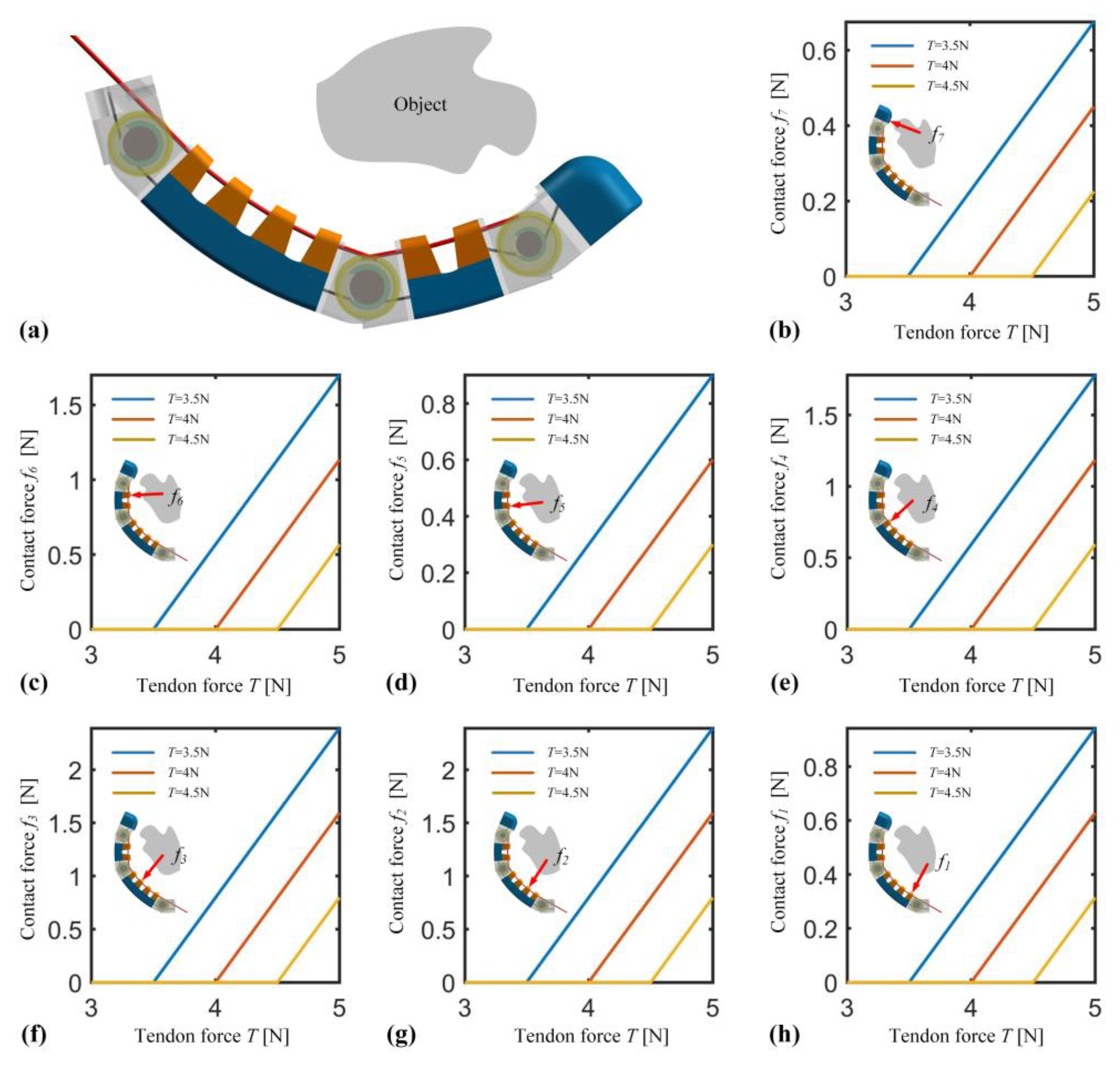
4.1. Contact Force Analysis

Building upon the mapping relationship established in the previous section between the contact force and driving torque of the robotic finger, this section initiates an analysis of the contact state within the enveloping grasp of the robotic hand. Given the small dimensions of the finger’s various link lengths, it is assumed that the contact points with the object are located at the mid-position of their respective links, i.e., l i x = l i 2 . Considering the scenario where the finger and the object have a single contact point, as the finger makes contact with the object, the contact force increases in tandem with the tendon force. Consequently, different links will exhibit varying contact forces due to this interaction. As shown in Figure 3, the contact and the variations in contact forces on different links are demonstrated when tendon forces of 3.5 N, 4 N, and 4.5 N are applied, respectively. Upon observation, it becomes apparent that following the initiation of contact, the alterations in contact forces on links 1 and 5 exhibit consistency, the changes on links 2 and 3 display correspondence, and the variations in links 4 and 6 maintain uniformity. Furthermore, these links that showcase consistent shifts in contact forces are situated at positions aligning with the MCP and PIP joints. This alignment indirectly suggests that the motion characteristics of the individual finger joints remain unaffected even after extending the rigid–soft unit to accommodate multi-joint fingers, taking as an example an instance where contact occurs between the finger and the object with T = 3.5 N, when T increases to 5 N, f 1 = f 5 = 0.94 N, f 4 = f 6 = 1.78 N, f 7 = 0.68 N. It is evident that when the contact point lies on links 2 and 3, the force transmission efficiency is the highest, followed by links 4 and 6.

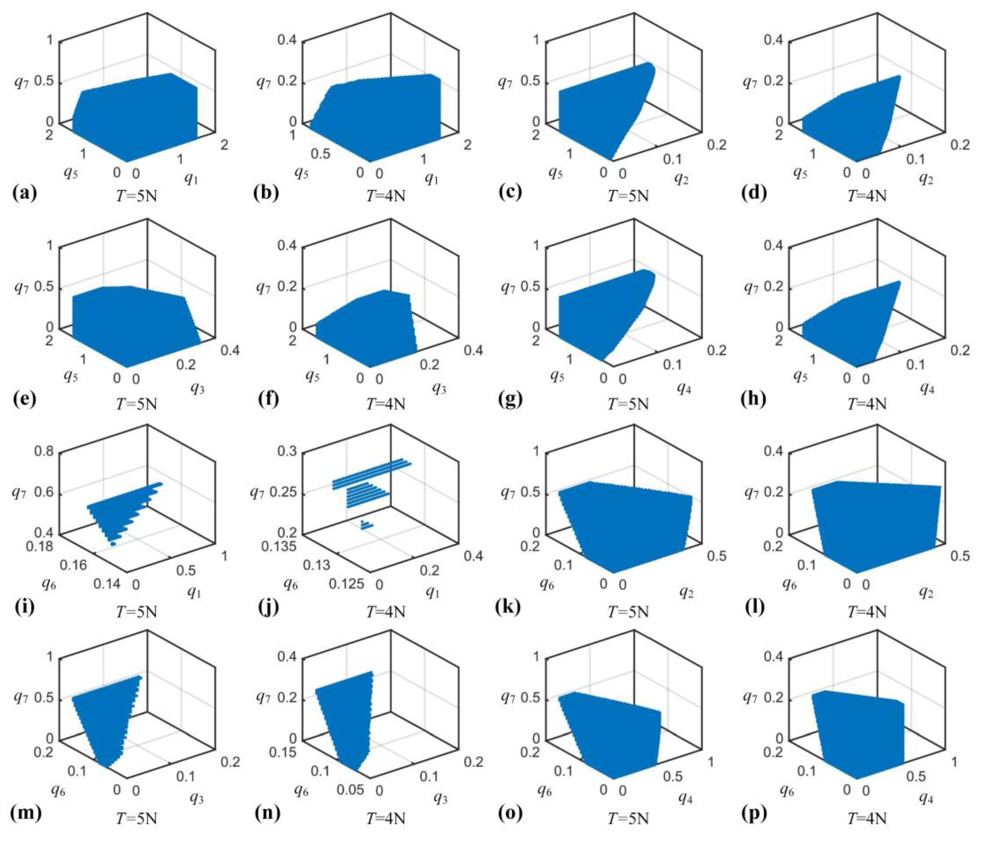
4.2. Stable Contact Region Analysis

On the basis of the aforementioned analysis of contact forces in robotic fingers, we delve deeper into understanding the contact states that arise as the fingers envelop objects. According to the design principles of robotic fingers, the torsion spring stiffness at elastic joints is significantly lower than the equivalent elastic stiffness of flexible finger segments. As a result, when the finger initially completes the process of enveloping an object, the flexible finger segments undergo minimal deformation. During this phase, the contact between each flexible finger segment and the object can still be approximated as a single-point contact. For the three-jointed fingers described in this paper, ensuring that each finger knuckle makes contact with the object contributes significantly to stabilizing the grasp. The precise location of the contact point on each knuckle directly influences the size of the stable contact region. To achieve this, we consider scenarios where there are three contact points as the finger envelops the object. We analyze how various contact configurations of the finger during this stage impact the attainment of a stable grasp. This analysis allows for a strategic planning of the finger’s contact positions with the object during the pre-grasping phase, ensuring the presence of a stable contact when the finger initially envelops the object. This approach mitigates the need for excessive tendon force to ensure stability during the initial enveloping of the object, thereby reducing energy consumption. It is important to note that, distinct from the approaches of shape closure and force closure in grasp planning, here we define stable contact between the finger and the object when the contact force at each contact point is greater than zero.
As depicted in Figure 1a and Figure 2b, the robotic finger’s MCP knuckle is composed of links 1, 2, 3, and 4, while the PIP knuckle is formed by links 5 and 6, and the DIP knuckle comprises link 7. When the finger initially envelops an object, three contact points are established, each positioned on a distinct joint. Consequently, there are a total of eight potential grasping contact configurations. As visualized in Figure 4, the stable contact regions of the robotic finger are displayed for various contact setups, with tendon forces of T = 4 N and T = 5 N taken into account. Notably, within the same grasping configuration, the stable contact region at T = 5 N surpasses that at T = 4 N, indicating that higher tendon forces facilitate the attainment of stable contact. The configurations featuring larger stable contact regions include cases where the contact points rest on links 1, 5, and 7, as well as links 2, 6, and 7, as shown in Figure 4. The subsequent favorable grasping configurations involve contact points on links 2, 5, and 7, links 3, 5, and 7, links 4, 5, and 7, and links 4, 6, and 7. Conversely, the grasping configurations with contact points on links 1, 6, and 7, as well as links 3, 6, and 7, exhibit smaller stable contact regions and are recommended to be avoided. Based on the aforementioned analysis, it is advisable to refrain from initiating contact with link 1 when the finger comes into contact with an object. The optimal grasping configuration involves contact points on links 2, 6, and 7. Furthermore, as discussed earlier in Figure 3, when the contact point resides on link 2, the force transmission efficiency peaks, leading to minimized energy dissipation.

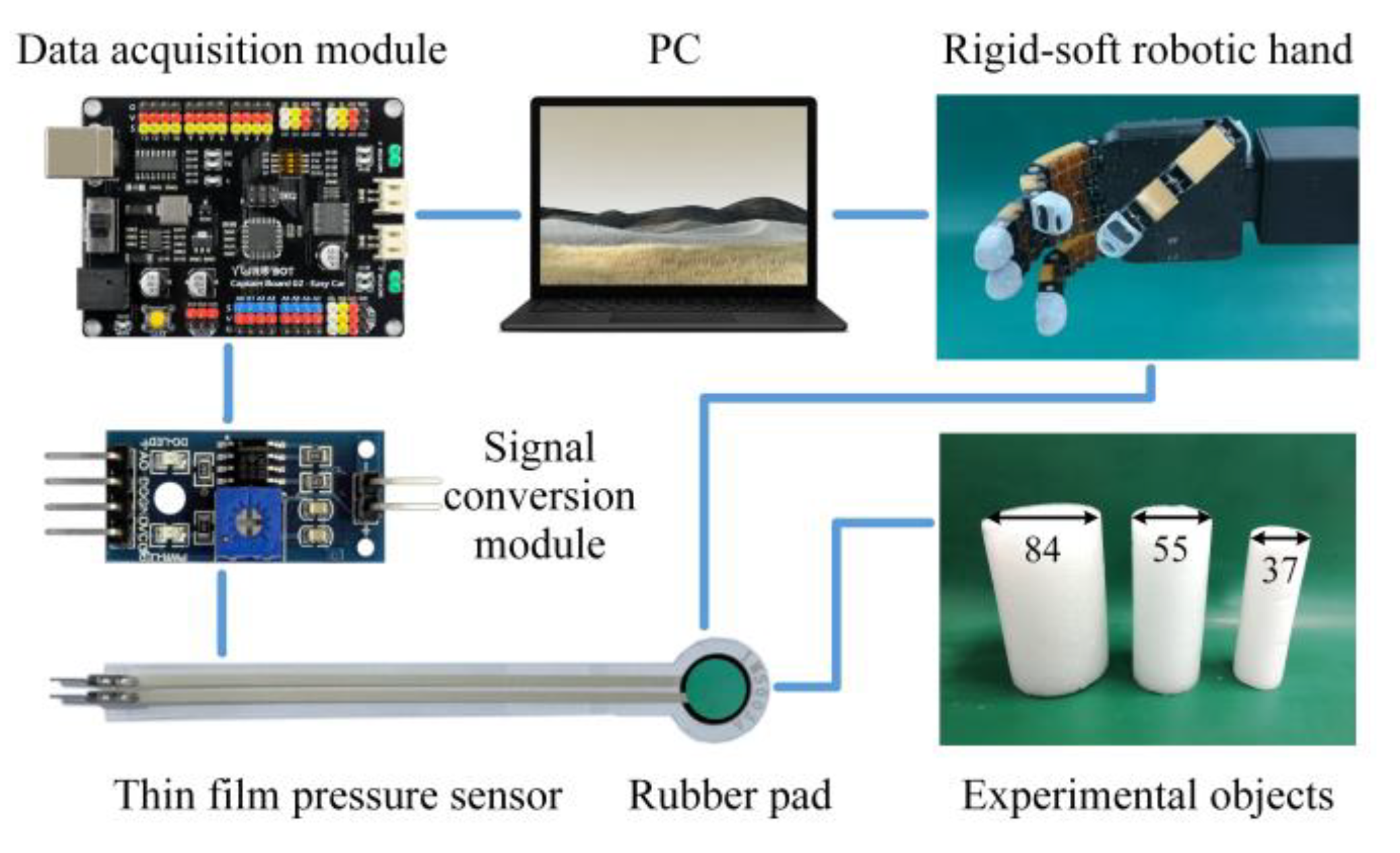
5. Experimental Validation

In this section, a comprehensive experimental validation was conducted, encompassing two distinct yet interrelated steps: experimental validation of contact forces and experimental validation of stable contact states. Through these steps, we aimed to rigorously assess the effectiveness of the proposed modeling and analytical approach in grasping scenarios of the anthropomorphic robotic hand.

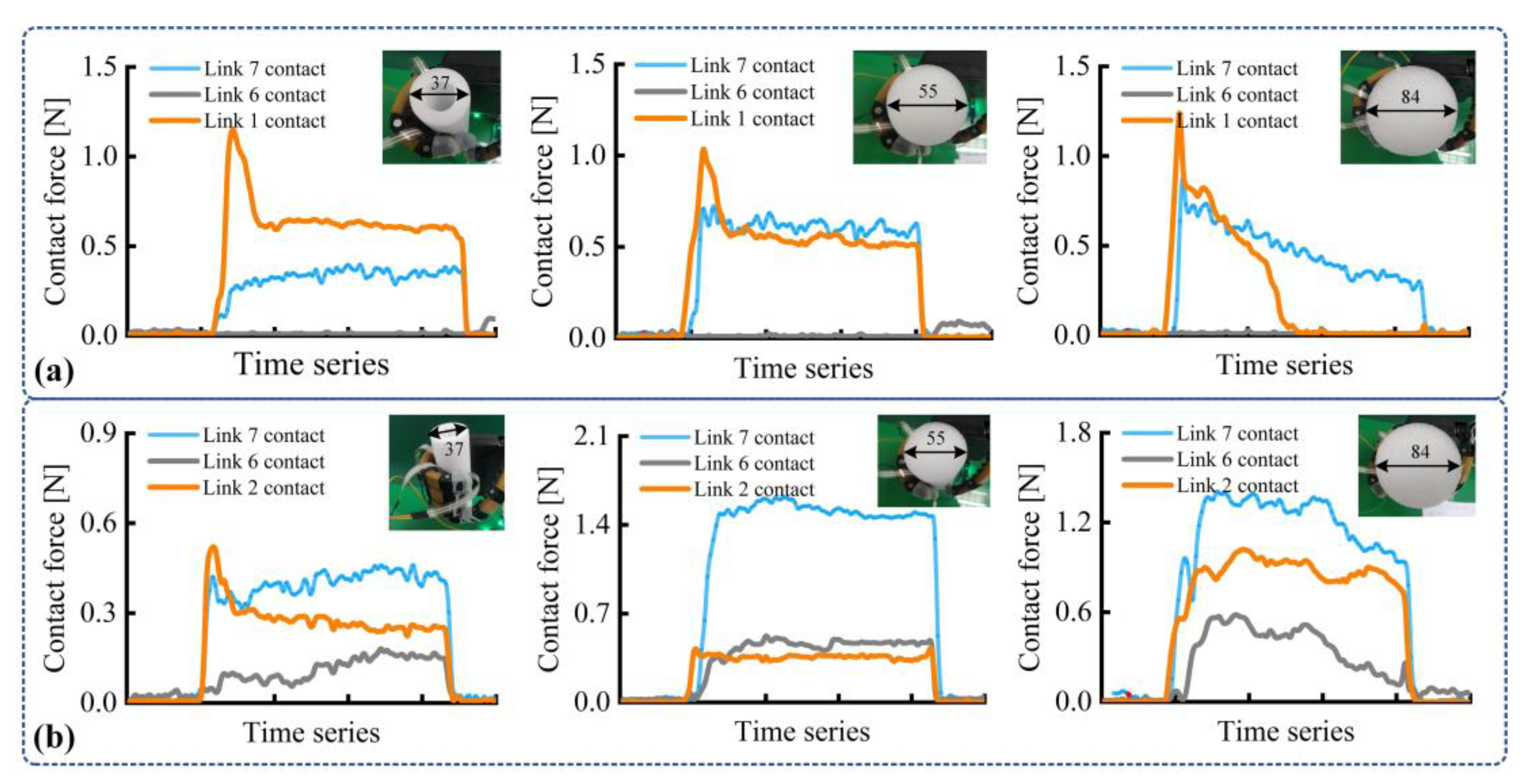
5.1. Experimental Validation of Contact Forces

To initiate the validation process, an experimental platform was first established to verify the accuracy of the contact force analysis when different finger links engage with an object. The experimental setup, depicted in Figure 5a, incorporated a six-axis force sensor for precise contact force measurements. Through keeping a certain grasping configuration uniformly, the six-axis force sensor was meticulously positioned to interact with links 1 and 5, respectively. The outcomes of these measurements are presented in Figure 4b, revealing an average absolute error of 0.09. It is crucial to note that the contact force curves for links 1 and 5 did not coincide precisely throughout the experiment, because the experiment time cannot be kept entirely consistent. For the sake of coherent comparison, these curves were thoughtfully shifted. This approach is reasonable, as we are focusing on the variation process of contact forces. Employing similar procedures, contact force measurement experiments were conducted for links 2 and 3, as well as links 4 and 6. The results are visually represented in Figure 4c,d, yielding average absolute errors of 0.03 and 0.12, respectively.
It is evident that, under uniform conditions, the measured contact forces on links 1 and 5 exhibit a notable alignment, as do those on links 2 and 3, and similarly on links 4 and 6. This robustly supports the accuracy of the prior contact force analysis findings. Furthermore, it is worth noting that the observed contact force discrepancies between links 1 and 5/links 4 and 6 surpass those observed between links 2 and 3. This divergence can be attributed to the physical separation between the respective link pairs on the finger, inducing a certain level of energy dissipation within the transmission mechanism. In addition, the contact force calculations proposed for the robotic finger were conducted under ideal conditions, introducing a degree of deviation from practical scenarios.

5.2. Experimental Validation of Stable Contact States

Further experiments were carried out to evaluate the effectiveness of the contact state analysis in the context of the anthropomorphic robotic hand. The experimental setup, illustrated in Figure 6, consisted of key components, including a PC, the anthropomorphic robotic hand, and circuit modules. The IMS-C10A thin film pressure sensors with a range spanning 0 to 10 N were chosen as the sensing instrument. To ensure optimal contact between the sensors and the object, and to mitigate potential measurement discrepancies due to finger flexion, carefully sized rubber pads were applied to the sensors’ surface. Cylindrical objects with varying diameters were selected as the experimental subjects. Leveraging insights from reference [33], these objects were considered as generally representative, thereby offering a practical approximation for a wide range of target objects. Prior to initiating the experiments, thorough pressure calibration was conducted for each sensor. The linear relationship between electrical conductivity and pressure was utilized to determine accurate contact pressure values on the sensors’ surface. Using adhesive backings, each sensor was meticulously attached to links 1, 6, and 7, as well as links 2, 6, and 7 of the robotic hand, namely, the positioning of pressure sensors. Considering both of these two distinct grasping configurations, the experimental investigation aimed to analyze the stability of contact during the process of the robotic hand grasping an object.
Considering the situations discussed above, experiments involving the grasping of cylindrical objects with distinct diameters were conducted to directly measure the real contact forces at different locations on the finger. Throughout these experiments, the finger gradually flexed until it fully enveloped the cylindrical object. Concurrently, contact forces were recorded at various points on the finger’s surface that were in contact with the object, as depicted in Figure 7. In cases where the contact points were positioned on links 1, 6, and 7, effective contact primarily occurred on links 1 and 7 ( f 1 > 0 , f 7 > 0 , f 6 = 0 ), as shown in Figure 7a. In addition, it can be seen that initial contact between the finger and link 1 often resulted in significant impact. For the 84 mm diameter cylindrical object, the contact point on link 1 became ineffective as the grasping motion advanced, with enveloping grasp achieved solely through effective contact with link 7. Conversely, in cases where contact points were located on links 2, 6, and 7, effective contact points were distributed across all three links throughout the process of enveloping various cylindrical objects ( f 2 > 0 , f 6 > 0 , f 7 > 0 ). This observation underscores that when employing this particular grasping configuration, the finger maintains stable contact as it initially envelopes the object. In summary, the aforementioned experiments convincingly validate the accuracy of the stable contact state analysis within the framework of the anthropomorphic robotic hand.

5.3. Discussion

In the experimental process, as shown in Figure 7, the anthropomorphic hand performs grasping action after manually placing target objects at planned positions using a human hand, and the position of the grasped object remains fixed. However, in real grasping scenarios, e.g., a robotic arm autonomously grasps objects by incorporating the anthropomorphic robotic hand, the objects’ position is not always fixed and may change with alterations in the grasping process. Building upon the foundation of this study, further research on the issue of handling non-resistant objects holds significant importance and practical value.
The analysis of stable contact states is common in rigid robotic hands. Typically, modeling is employed to quantify their stable contact regions. This paper extends its application to rigid–soft anthropomorphic hands and provides the contact conditions for achieving stable grasping. We can plan grasping configuration using the proposed method. However, in daily grasping tasks, it is often common to randomly plan the grasping configuration. We further compared the grasping performance of these two methods, as shown in Figure 8. For the random planning method, the finger has only one contact point with the object. For the proposed method, the finger has multiple contact points with the object. Because multiple points of contact contribute to stable grasping, this comparative experiment further illustrates the advantages of the approach presented in this paper.

6. Conclusions

The focus of this study revolves around the developed anthropomorphic robotic hand with soft materials and rigid structures, which serves as the experimental subject. Within this context, a modeling and analysis method for stable contact states has been introduced, considering the characteristic of the anthropomorphic robotic hand’s compliant contact. The proposed kinetostatic modeling approach, rooted in the pseudo-rigid-body model, facilitates the mapping of grasp contact forces to driving torques, enabling a detailed investigation of stable contact states across a range of varied grasping scenarios. On this basis, stable contact can be maintained during the initial grasping phase, by judiciously planning the finger–object contact positions. For instance, to ensure a reliably stable initial contact, it is recommended to avoid establishing contact with link 1, and instead, favor an optimal grasping configuration characterized by contact points on links 2, 6, and 7. The method presented herein effectively characterizes the evolving contact state of the robotic hand throughout the grasping process, ensuring a stable initial contact. This endeavor contributes to the robotic hand’s capability to stably grasp objects, consequently bolstering reliability.

Author Contributions

Conceptualization, M.C., Y.D. and L.J.; methodology, Y.L. (Yongyao Li); software, Y.L. (Yongyao Li); validation, Y.L. (Yongyao Li), Q.L. and Y.Z.; formal analysis, Y.L. (Yongyao Li); investigation, Y.L. (Yongyao Li); resources, Y.L. (Yongyao Li); data curation, Y.L. (Yufei Liu) and C.Y.; writing—original draft preparation, Y.L. (Yongyao Li); writing—review and editing, Y.L. (Yufei Liu) and Z.S.; visualization, Y.L. (Yongyao Li) and D.Z.; supervision, M.C. and L.J.; project administration, M.C. and L.J.; funding acquisition, Y.L. (Yongyao Li), Y.L. (Yufei Liu) and M.C. All authors have read and agreed to the published version of the manuscript.

Funding

This research was funded by the National Natural Science Foundation of China, grant number 52205035 and the China Postdoctoral Science Foundation, grant number 2023M733284.

Data Availability Statement

The data presented in this study are available on request from the corresponding authors.

Acknowledgments

The authors would like to thank all the project partners for their valuable contribution.

Conflicts of Interest

The authors declare no conflicts of interest.

References

  1. Billard, A.; Kragic, D. Trends and challenges in robot manipulation. Science 2019, 364, eaat8414. [Google Scholar] [CrossRef]
  2. Chen, W.; Xiong, C.; Chen, W.; Yue, S. Mechanical adaptability analysis of underactuated mechanisms. Robot. Com-Int. Manuf. 2018, 49, 436–447. [Google Scholar] [CrossRef]
  3. Palli, G.; Melchiorri, C.; Vassura, G.; Scarcia, U.; Moriello, L.; Berselli, G.; Cavallo, A.; De Maria, G.; Natale, C.; Pirozzi, S. The DEXMART hand: Mechatronic design and experimental evaluation of synergy-based control for human-like grasping. Int. J. Robot. Res. 2014, 33, 799–824. [Google Scholar] [CrossRef]
  4. Chen, W.; Xiong, C. Adaptability analysis, evaluation and regulation of compliant underactuated mechanisms. In Proceedings of the IEEE/RSJ International Conference on Intelligent Robots & Systems (IROS), Hamburg, Germany, 28 September–2 October 2015; pp. 6039–6046. [Google Scholar]
  5. Yao, S.; Ceccarelli, M.; Carbone, G.; Dong, Z. Grasp configuration planning for a low-cost and easy-operation underactuated three-fingered robot hand. Mech. Mach. Theory 2018, 129, 51–69. [Google Scholar] [CrossRef]
  6. Deng, Z.; Jonetzko, Y.; Zhang, L.; Zhang, J. Grasping force control of multi-fingered robotic hands through tactile sensing for object stabilization. Sensors 2020, 20, 1050. [Google Scholar] [CrossRef] [PubMed]
  7. Kim, D.; Lee, J.; Chung, W.; Lee, J. Artificial intelligence-based optimal grasping control. Sensors 2020, 20, 6390. [Google Scholar] [CrossRef] [PubMed]
  8. Kappassov, Z.; Corrales, J.; Perdereau, V. Tactile sensing in dexterous robot hands-a review. Robot. Auton. Syst. 2015, 74, 195–220. [Google Scholar] [CrossRef]
  9. Liu, H.; Nguyen, K.C.; Perdereau, V.; Bimbo, J.; Back, J.; Godden, M.; Seneviratne, L.D.; Althoefer, K. Finger contact sensing and the application in dexterous hand manipulation. Auton. Robot. 2015, 39, 25–41. [Google Scholar] [CrossRef]
  10. Bicchi, A.; Salisbury, J.K.; Brock, D.L. Contact sensing from force measurements. Int. J. Robot. Res. 1993, 12, 249–262. [Google Scholar] [CrossRef]
  11. Murray, R.M.; Li, Z.; Sastry, S.S. A Mathematical Introduction to Robotic Manipulation; CRC Press: Boca Raton, FL, USA, 2017. [Google Scholar]
  12. Romano, J.M.; Hsiao, K.; Niemeyer, G.; Chitta, S.; Kuchenbecker, K.J. Human-inspired robotic grasp control with tactile sensing. IEEE T Robot. 2011, 27, 1067–1079. [Google Scholar] [CrossRef]
  13. Lin, M.A.; Thomasson, R.; Uribe, G.; Choi, H.; Cutkosky, M.R. Exploratory hand: Leveraging safe contact to facilitate manipulation in cluttered spaces. IEEE Robot. Autom. Lett. 2021, 6, 5159–5166. [Google Scholar] [CrossRef]
  14. Backus, S.B.; Dollar, A.M. Robust resonant frequency-based contact detection with applications in robotic reaching and grasping. IEEE-ASME T Mech. 2013, 19, 1552–1561. [Google Scholar] [CrossRef]
  15. Homberg, B.S.; Katzschmann, R.K.; Dogar, M.R.; Rus, D. Robust proprioceptive grasping with a soft robot hand. Auton. Robot. 2019, 43, 681–696. [Google Scholar] [CrossRef]
  16. Del Sol, E.; King, R.; Scott, R.; Ferre, M. External force estimation for teleoperation based on proprioceptive sensors. Int. J. Adv. Robot. Syst. 2014, 11, 52. [Google Scholar] [CrossRef]
  17. Della Santina, C.; Piazza, C.; Santaera, G.; Grioli, G.; Catalano, M.; Bicchi, A. Estimating contact forces from postural measures in a class of under-actuated robotic hands. In Proceedings of the IEEE/RSJ International Conference on Intelligent Robots and Systems (IROS), Vancouver, BC, Canada, 24–28 September 2017; pp. 2456–2463. [Google Scholar]
  18. Shan, X.; Birglen, L. Modeling and analysis of soft robotic fingers using the fin ray effect. Int. J. Robot. Res. 2020, 39, 1686–1705. [Google Scholar] [CrossRef]
  19. Zhou, J.; Chen, Y.; Chen, X.; Wang, Z.; Li, Y.; Liu, Y. A proprioceptive bellows (PB) actuator with position feedback and force estimation. IEEE Robot. Autom. Lett. 2020, 5, 1867–1874. [Google Scholar] [CrossRef]
  20. Kaneko, M.; Tanie, K. Contact point detection for grasping an unknown object using self-posture changeability. IEEE Trans. Robot. Autom. 1994, 10, 355–367. [Google Scholar] [CrossRef]
  21. Belzile, B.; Birglen, L. Stiffness analysis of double tendon underactuated fingers. In Proceedings of the IEEE International Conference on Robotics & Automation (ICRA), Hong Kong, China, 31 May–7 June 2014; pp. 6679–6684. [Google Scholar]
  22. Pastor, F.; Gandarias, J.M.; García-Cerezo, A.J.; Muñoz-Ramírez, A.J.; Gómez-De-Gabriel, J.M. Grasping angle estimation of human forearm with underactuated grippers using proprioceptive feedback. In Proceedings of the Iberian Robotics Conference, Porto, Portugal, 20–22 November 2019; pp. 441–452. [Google Scholar]
  23. Karayiannidis, Y.; Smith, C.; Vina, F.E.; Kragic, D. Online contact point estimation for uncalibrated tool use. In Proceedings of the IEEE International Conference on Robotics and Automation (ICRA), Hong Kong, China, 31 May–7 June 2014; pp. 2488–2494. [Google Scholar]
  24. Park, M.; Jeong, B.; Park, Y. Hybrid system analysis and control of a soft robotic gripper with embedded proprioceptive sensing for enhanced gripping performance. Adv. Intell. Syst. 2021, 3, 2000061. [Google Scholar] [CrossRef]
  25. Abdeetedal, M.; Kermani, M.R. Grasp and stress analysis of an underactuated finger for proprioceptive tactile sensing. IEEE-ASME T Mech. 2018, 23, 1619–1629. [Google Scholar] [CrossRef]
  26. Deckers, P.; Dollar, A.M.; Howe, R.D. Guiding grasping with proprioception and Markov models. In Proceedings of the Robotics: Science and Systems Conference (RSS), Atlanta, GA, USA, 30 June 2007. [Google Scholar]
  27. Korenblik, J. Minimal Sensing Approach of an Underactuated Flexure Based Gripper for Agri-Food Applications; University of Twente: Enschede, The Netherlands, 2021. [Google Scholar]
  28. Li, Y.; Cong, M.; Liu, D.; Du, Y. A practical model of hybrid robotic hands for grasping applications based on bioinspired form. J. Intell. Robot. Syst. 2022, 105, 73. [Google Scholar] [CrossRef]
  29. Venkiteswaran, V.K.; Su, H. A three-spring pseudorigid-body model for soft joints with significant elongation effects. J. Mech. Robot. 2016, 8, 061001. [Google Scholar] [CrossRef]
  30. Hunt, K.H. Kinematic Geometry of Mechanisms; Oxford University Press: New York, NY, USA, 1990. [Google Scholar]
  31. Cutkosky, M.R. On grasp choice, grasp models, and the design of hands for manufacturing tasks. IEEE Trans. Robot. Autom. 1989, 5, 269–279. [Google Scholar] [CrossRef]
  32. Li, Y.; Cong, M.; Liu, D.; Du, Y.; Xu, X. Stable grasp planning based on minimum force for dexterous hands. Intell. Serv. Robot. 2020, 13, 251–262. [Google Scholar] [CrossRef]
  33. Chen, W.; Xiong, C. On adaptive grasp with underactuated anthropomorphic hands. J. Bionic Eng. 2016, 13, 59–72. [Google Scholar] [CrossRef]
Figure 1. The overall structure of the rigid–soft anthropomorphic hand. (a) The design principle of the rigid–soft anthropomorphic finger. (b) The anthropomorphic robotic hand.
Electronics 13 01319 g001
Figure 2. Simplified model and related parameters of the rigid–soft robotic finger. (a) Simplified method of the robotic finger. (b,c) The physical and geometric parameters of the robotic finger.
Electronics 13 01319 g002
Figure 3. Contact force calculation of the rigid–soft anthropopathic finger. (a) The robotic finger comes into contact with an object. (b) The variation in the contact force f7 on link 7 under the tendon forces T = 3.5 N, T = 4 N, T = 5 N, respectively. (c) The variation in the contact force f6 on link 6 under the tendon forces T = 3.5 N, T = 4 N, T = 5 N, respectively. (d) The variation in the contact force f5 on link 5 under the tendon forces T = 3.5 N, T = 4 N, T = 5 N, respectively. (e) The variation in the contact force f4 on link 4 under the tendon forces T = 3.5 N, T = 4 N, T = 5 N, respectively. (f) The variation in the contact force f3 on link 3 under the tendon forces T = 3.5 N, T = 4 N, T = 5 N, respectively. (g) The variation in the contact force f2 on link 2 under the tendon forces T = 3.5 N, T = 4 N, T = 5 N, respectively. (h) The variation in the contact force f1 on link 1 under the tendon forces T = 3.5 N, T = 4 N, T = 5 N, respectively.
Electronics 13 01319 g003
Figure 4. Stable contact regions of the envelope grasping for the anthropomorphic robotic hand. (a,b) Stable contact regions under the grasping configuration of the link 1, 5, 7 when the tendon forces T = 5 N, T = 4 N, respectively. (c,d) Stable contact regions under the grasping configuration of the link 2, 5, 7 when the tendon forces T = 5 N, T = 4 N, respectively. (e,f) Stable contact regions under the grasping configuration of the link 3, 5, 7 when the tendon forces T = 5 N, T = 4 N, respectively. (g,h) Stable contact regions under the grasping configuration of the link 4, 5, 7 when the tendon forces T = 5 N, T = 4 N, respectively. (i,j) Stable contact regions under the grasping configuration of the link 1, 6, 7 when the tendon forces T = 5 N, T = 4 N, respectively. (k,l) Stable contact regions under the grasping configuration of the link 2, 6, 7 when the tendon forces T = 5 N, T = 4 N, respectively. (m,n) Stable contact regions under the grasping configuration of the link 3, 6, 7 when the tendon forces T = 5 N, T = 4 N, respectively. (o,p) Stable contact regions under the grasping configuration of the link 4, 6, 7 when the tendon forces T = 5 N, T = 4 N, respectively.
Electronics 13 01319 g004
Figure 5. Contact force experiments of the anthropopathic robotic finger. (a) Experimental setup for contact force validation. (b) The variation in the contact forces on links 1 and 5, respectively. (c) The variation in the contact forces on links 2 and 3, respectively. (d) The variation in the contact forces on links 4 and 6, respectively.
Electronics 13 01319 g005
Figure 6. Experimental apparatus setup for stable contact state validation.
Electronics 13 01319 g006
Figure 7. Grasping experiments for evaluating the stable contact states of the anthropomorphic robotic hand. (a) Grasping experimental case where contact points were located on links 1, 6, and 7. (b) Grasping experimental case where contact points were located on links 2, 6, and 7.
Electronics 13 01319 g007
Figure 8. Comparative experiments on real-world applications.
Electronics 13 01319 g008
Disclaimer/Publisher’s Note: The statements, opinions and data contained in all publications are solely those of the individual author(s) and contributor(s) and not of MDPI and/or the editor(s). MDPI and/or the editor(s) disclaim responsibility for any injury to people or property resulting from any ideas, methods, instructions or products referred to in the content.

