1. Introduction
PMSM is widely used in various motor driving applications because of its simple structure, stable speed, high reliability, and high efficiency [
1,
2,
3]. The development of rare earth materials and modern power electronic control technology has further improved the control performance of PMSM, so the aviation electromechanical actuator system also uses a large number of PMSMs with superior performance [
4,
5].
PID control is extensively used in motor manipulation structures in a range of fields due to its ease and handy parameter adjustment. However, aviation electromechanical actuation systems often have to face extremely harsh working environments, such as low-temperature turbulence, and the external disturbance changes greatly, which requires very high disturbance resistance and robustness of the control system. However, simple PID control can only be applied to areas with low motor stability and safety requirements, and it is convenient to produce giant overharmonic torque ripple in the face of load conditions such as the unexpected alternate of the motor load. The predictive flux control model proposed by Gao et al. [
6] introduced the zero vector into the alternative vector set to reduce the current harmonic content and quickly selects the voltage vector according to the flux error vector, which reduces the torque ripple of the motor. Wang et al. [
7] proposed a new kind of lengthy predictive time area direct modern mannequin predictive management method, which effectively reduces the current harmonics and torque ripple of the motor. MohammadHadi et al. [
8] proposed that non-stop manipulation set mannequin predictive management has the capacity to tune reference values with zero steady-state error for motor controllers. This technique can also achieve a quick dynamic response to motors, with a complete harmonic distortion that is significantly lower than that of finite manage set mannequin predictive control. Chen et al. [
9] analyzed the impact of a number of parameters on the motor torque in accordance with the distinct influencing elements via the finite thing model and proposed that the no-load torque of the motor should be suppressed by way of optimizing the structural parameters of the motor, and the ripple torque of the motor should be suppressed by optimizing the winding position.
Zhou et al. [
10] combined as genetic algorithm and TOPSIS method to optimize the global multi-objective motor and improve the torque ripple suppression ability of the high-speed motor. At the same time, the method of suppressing motor torque pulsation based on harmonic current injection [
11,
12] studied by a large number of scholars has become more mature. Wang et al. [
13] proposed an adaptive linear neural network harmonic injection method based on biased current input. Based on the cross-coupling effect of the motor, Zheng et al. [
14] proposed an approach of motor torque ripple inhibition primarily based on optimum harmonic present-day injection. Wu et al. [
15] proposed a highest-quality-voltage harmonic injection speed harmonic minimization approach based totally on amplitude and section evaluation of the influence of injection voltage harmonic amplitude and section on speed harmonic amplitude. Guo et al. [
16] proposed a torque ripple suppression approach considering the harmonic flux segment angle, built a goal feature considering each torque ripple and loss minimization with the aid of deducing a torque mannequin considering harmonic flux, and optimized the best harmonic modern by means of a genetic algorithm. Hyung-Jin et al. [
17] utilized adaptive manipulation to compensate for the torque ripple of the motor. Zhang et al. [
18] blended the three-parameter notch filter and linear lively disturbance rejection controller to suppress the contemporary harmonics of the motor, which weakens the impact of the present-day harmonics on the torque’s overall performance of the motor. Based on the evaluation of the relationship between the pulsation aspect in the torque and the modern-day pulsation factor in the motor, Zhou et al. [
19] proposed an improved closed-loop frequency compensation strategy to eliminate the pulsation component in the motor torque. Huang et al. [
20] introduced fractional order operation into the resonant controller and designed a robust internal model controller.
In addition, many scholars whose studies were based totally on PI management and energetic disturbance rejection manipulation studied motor torque ripple suppression strategies. Yuan et al. [
21] proposed a current double closed-loop control strategy with PI control in the inner loop and repeated control in the outer loop. Wang et al. [
22] suppressed the modern torque of the motor by way of designing a Chebyshev filter blended with PI control. Based on the evaluation of singular perturbation idea and common theorem, Tian et al. [
23] proposed a current loop adaptive disturbance rejection control. Liu et al. [
24] accelerated the lively disturbance rejection management via the usage of the prolonged country observer in a parallel resonant unit, which can efficiently suppress the torque pulsation of zero sequence current and third harmonic back potential.
In order to suppress the torque pulsation of PMSM used in aviation electromechanical actuation systems and enhance the reliability of the managed system, due to the complicated working surroundings of PMSM in aviation electromechanical actuation systems and frequent workload changes, the dynamic performance of the motors is required to be higher. In this paper, a fuzzy-ADRC torque ripple suppression technique of PMSM primarily based on a three-phase four-bridge inverter is proposed. In this method, a three-phase four-bridge inverter is used to change the three-phase three-bridge inverter, and the fourth bridge arm of the three-phase four-bridge inverter can filter out the contemporary harmonics when the load changes, so as to suppress the torque ripple of the motor. The ADRC is used to substitute PI control to control the motor. The ADRC makes use of the prolonged state observer (ESO) to observe the essential variables of the PMSM device to track and compensates for the control system with the observed values in the feedback control link, which solves the problem where the response speed and overfire of PI control are hard to balance. On this basis, the Kalman filter is brought to the motor speed ring to similarly enhance the ADRC and enhance the steadiness of the motor speed control. The fuzzy control can regulate the parameters of the nonlinear error feedback control rate in the ADRC in real time, enhance the balance of the system, solve the problem that there are too many ADRC parameters and the setting is too complicated, and similarly enhance the torque pulsation suppression overall performance of PMSM. Simulation consequences exhibit that the proposed technique is correct and effective.
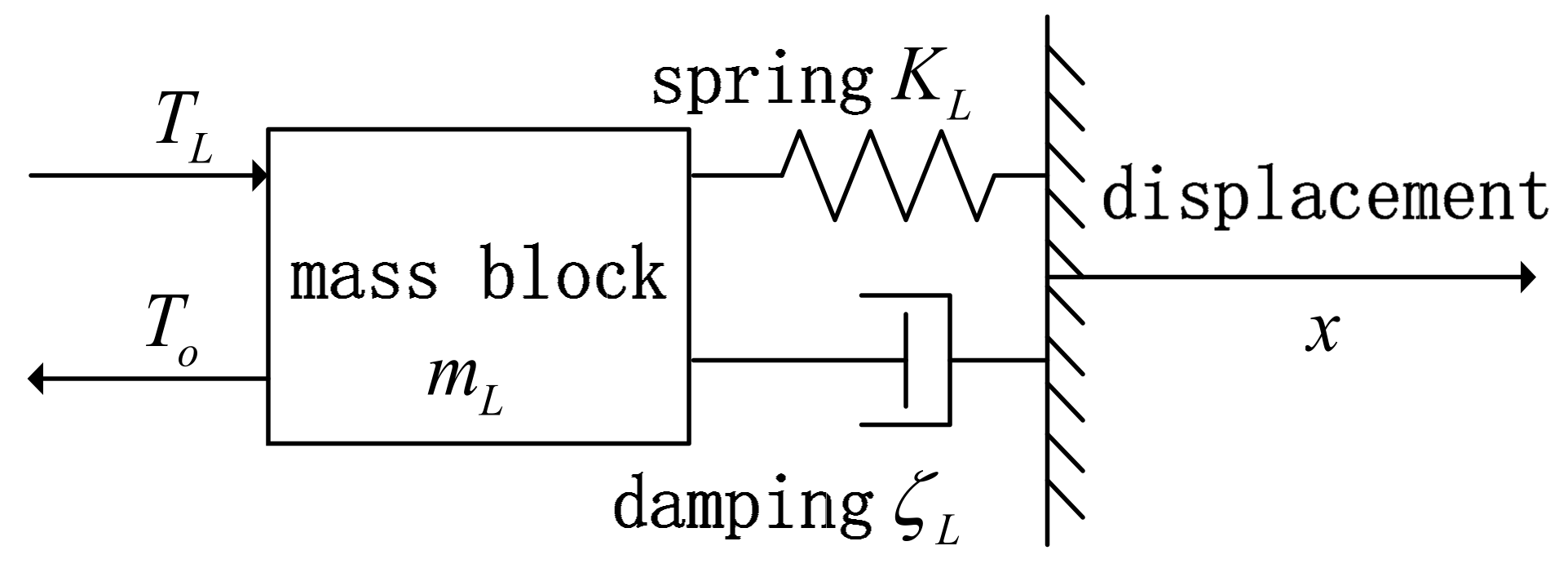
3. Mathematical Model of the Aviation Electromechanical Transmission System
The aviation electromechanical actuation system mainly includes a clutch, roller screw, and push rod. The electromechanical actuation system transfers the output torque of the PMSM to the screw of the roller screw via the clutch and converts the rotating motion of the motor into linear displacement via this process. The mechanical and electrical actuation system composed of the clutch, roller screw, and push rod is modeled equivalently. Firstly, the controlled system is analyzed by a dynamic model, which can be generally equivalent to
Figure 1.
In
Figure 1,
and
, respectively, represent the driving force required by the load and the torque caused by the load interference;
is the elastic spring coefficient;
is the damping coefficient of the system;
is the mass of the mass block in the load; and
is the displacement. According to the load dynamics model, the following can be obtained:
Applying the Laplace transform to the above equation gives
According to the above formula, the transmission mechanism of the aviation electromechanical actuation system is equivalent to
Figure 2.
Among them,
and
are, respectively, the rotation angle of the PMSM and the torque transmitted to the mechanical transmission mechanism;
represents the equivalent torsional stiffness of the roller screw;
represents the equivalent moment of inertia;
represents the damping coefficient;
represents the angular displacement of the ball screw obtained after the load-displacement distance is converted; and
is the resistance of the roller screw. According to the above model, the equations of motion and torque of the mechanical transmission system of the electromechanical actuation actuator can be obtained as follows:
The Laplace transform of the above equation gives
After sorting out the above formula, we obtain
The rotation angle of the roller screw 1 is converted into the linear displacement of the push rod 2 to obtain
In the above formula, is the lead of the roller lead screw.
4. Three-Phase Four-Leg Inverter
The three-phase four-bridge arm inverter connects the fourth bridge arm to the motor center line to solve the problem of capacitor neutral point imbalance and overmargin, and the inductor with a neutral line in the series can filter out the switching ripple when the motor load changes, acting as a filter.
When the load of a PMSM changes abruptly, the current and torque of the motor fluctuate violently under the influence of sudden load. The three-phase four-bridge inverter has the function of a filter, which can filter out the current harmonics induced by using the unexpected change of the motor load, thus reducing the torque and current ripple of the motor and avoiding the problem of motor efficiency reduction caused by current harmonics caused by complex sudden change.
The three-phase four-bridge inverter is shown in
Figure 3.
In
Figure 3,
and
form the A bridge arm;
and
form the B bridge arm;
and
form the C bridge arm;
and
form the fourth bridge arm.
is the DC voltage source;
is the additional inductance.
,
, and
are the output voltages;
,
, and
are currents of the inverter;
and
represent the voltage and current of the fourth bridge arm of the inverter.
Suppose the midline current is
, the zero-axis current can be expressed as
as follows:
It can be seen from Formula (10) that the line current can be controlled indirectly by controlling the change of the zero-axis current . In normal operation, the center line current is 0, which only needs to control the zero-axis current , which is 0.
The PMSM normal operation is as follows:
At this time, the three-phase currents are, respectively,
When the load changes abruptly, the three-phase output voltage can be decomposed into three balanced positive sequence, negative sequence, and zero sequence components, and the motor voltage can be expressed as
where
and
are the voltage peaks of positive sequence and negative sequence, respectively;
and
are the initial phases of positive and negative sequence voltages, respectively.
5. Design of Active Disturbance Rejection Controller
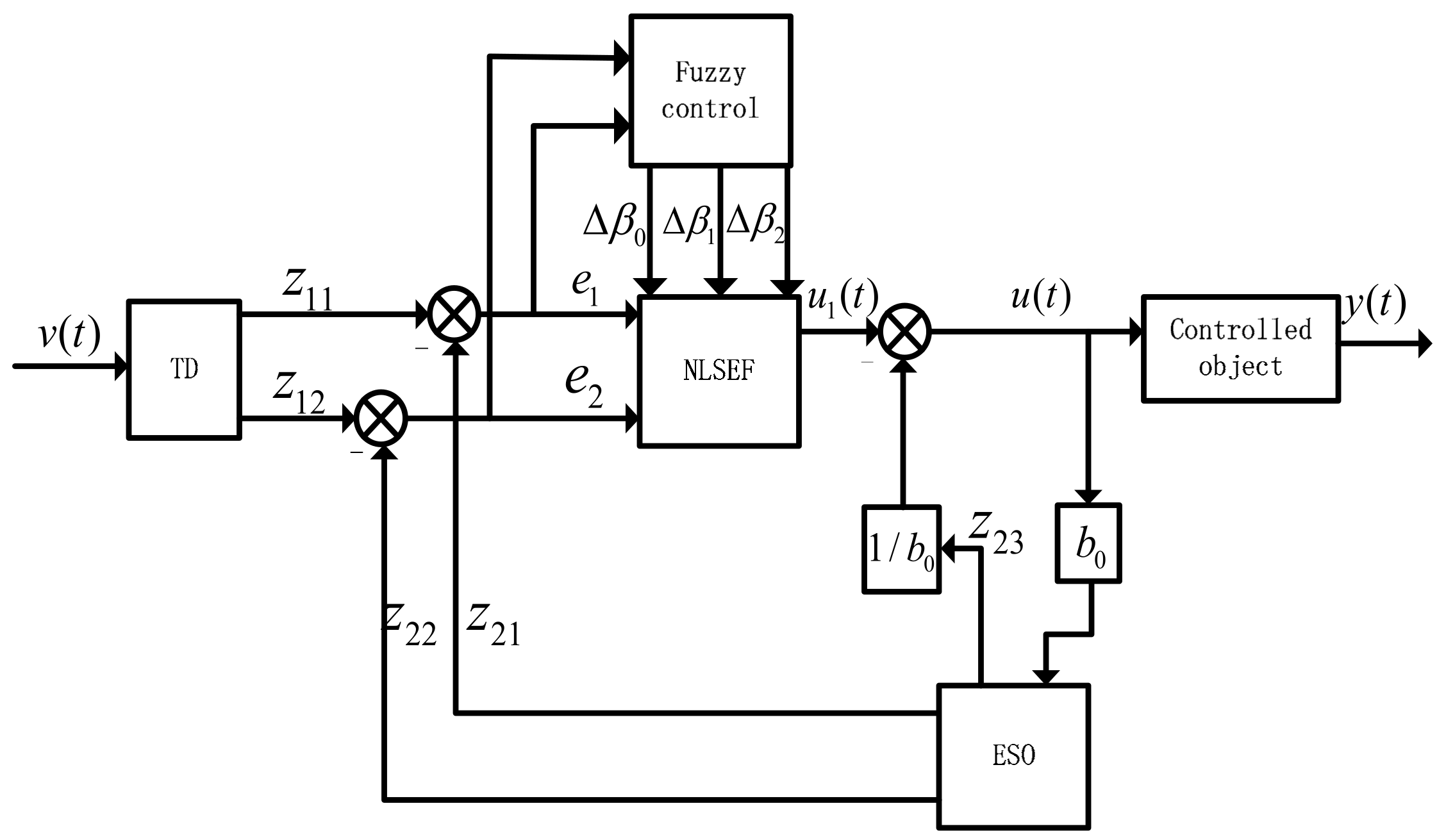
The tracking differentiator (TD) extracts the signal of the managed object, and the extended state observer (ESO) compensates for the whole disturbance inside and outside the device to enhance the safety and balance of the system. Then, the signal extracted by the TD is used as the input of the nonlinear state error feedback control law (NLSEF). The total control value of the fuzzy-ADRC is obtained by combining the output of the NLSEF control rate with the total disturbance compensation value of the extended state observer.
The structure diagram of ADRC is shown in
Figure 4.
5.1. Tracking Differentiator
As the input part of the ADRC, the TD creates a reasonable arrangement for the input signal transition to solve the overshoot problem of PI control.
The standard form of a TD is as follows:
where
is the input signal, and its tracking value
can reflect the performance of TD;
to
are the differentials of the trace values; the speed factor is
. Function
in the formula can reduce the high-frequency oscillation of the system, and the expression of
is as follows:
In the formula, is defined as a nonlinear factor; is the system tracking error; is the filtering factor of the fal function. The larger the filtering factor, the better the filtering effect, but this will lead to tracking delay. When , . When , has the peculiarity of “small error with large gain, large error with small gain”.
5.2. Extended State Observer
ESO re-extends the output value of the controlled object into a variable and estimates and compensates for the system disturbance by each derivative signal
; the output signal
and the system disturbance are estimated by signal
, and a new state variable is obtained. The new state variable equation obtained through the above process is
In Formula (16), is the estimated value of the system, is the observed value of each order variable of the system, is the total disturbance, and represent the gain coefficients of the ESO, and represents the output value of the ADRC.
5.3. Nonlinear State Error Feedback Control Law
The application of nonlinear functions in ADRC can effectively deal with the overshoot problem of the controlled system. Error signal and error differential signal of the transition process are generated based on the tracking differentiator method, and finally, the error integral signal is generated. The state error feedback control rate is obtained by combining the error, error differential, and error integral. The n-order nonlinear feedback expression is as follows:
where
is the difference between the input value and each order differential value of the controlled quantity.
is the trace value of the input value
,
to
are the differentials of the trace values, and
is the observed value of each order variable of the system.
,
, and
are the filter factor, the nonlinear factor, and the feedback output of the NLSEF, respectively.
5.4. Improved Active Disturbance Rejection Control
To enhance the technology of the ADRC of PMSM to effectively suppress the torque ripple, the Kalman filter is added to the loop ADRC of PMSM.
Assume that the controlled system is a discrete system and is perturbed, and its output equation and state equation are
In the above formula,
and
are the system state and output value;
represents the control quantity of the controlled at moment
;
,
, and
, respectively, represent the transfer matrix, system matrix, and measurement matrix of the controlled system;
is the process noise of the system;
is the measurement noise received during the measurement process. It can be assumed that
and
are Gaussian white noise, and the mean value of the signal is 0; then,
and
meet the following conditions:
In Formula (19), and are both covariance matrices.
Kalman filter control is mainly divided into two processes: the first process is prediction, and the second process is correction. In the prediction process,
and
of the controlled system at moment
should be promptly corrected, and the corresponding state-predicted value and error covariance matrix at moment
of the next time point should be obtained. The calculation formula of this process is as follows:
In the above formula, and , respectively, represent the state-predicted value and error covariance matrix at time ; and are the state-predicted value and error covariance matrix when the time is .
The correction process of the Kalman filter includes three steps: calculation of the gain, correction of the state estimate obtained in the prediction process, and correction of the error covariance obtained in the process of making predictions. The above calculation process is shown in Formula (21):
From Formula (21), represents the gain calculation, represents the correction of the state predicted value from the prediction when the time is , and represents the correction of the error covariance from the prediction at time .
6. Design of Fuzzy Active Disturbance Rejection Controller
Although compared with PID control, ADRC can improve the torque ripple suppression ability of the motor to some extent, more parameters need to be adjusted for ADRC, which increases the difficulty of parameter adjustment in the actual control process. However, according to the real-time state change of the controlled system, fuzzy control adjusts the parameters of ADRC. The first step of fuzzy control is fuzzization, the second step is fuzzy reasoning, and the third step is defuzzification. Fuzzy control solves the complex problem of parameter tuning of ADRC.
Fuzzy control first converts the input quantity into fuzzy quantity via fuzzification; then, the fuzzy quantity collected in the previous step is applied to the fuzzy inference process via the fuzzy rules; and finally, the fuzzy quantity obtained by fuzzy inference is converted into the precise quantity required by control by fuzzification. A second-order ADRC is used here. The principle of fuzzy-ADRC is shown in
Figure 5.
In the above figure, and are the input quantity of fuzzy control, ; and are the exact output after unfuzzing; and the fuzzy subset is set as {“negative large (NB)”, “negative medium (NM)”, “negative small (NS)”, “zero (ZO)”, “positive small (PS)”, “middle (PM)”, “positive large (PB)”}.
Here, the membership functions of
,
, and
are set to a triangular shape, and the rule functions of the input and output of fuzzy control are set to the membership function form of the middle triangle of the normal distribution on both sides. The basic discourse domain of
and
is set as [−3, 3]. The fundamental domain of
and
is [−0.3, 0.3], and the fundamental domain of
is [−0.06, 0.06]. The Mandani method is used for fuzzy reasoning of fuzzy control, and the center of gravity method is used in the process of defuzzification.
Figure 6 shows the regular function curves of
and
,
Figure 7 shows the regular function curves of
and
, and
Figure 8 shows the regular function curves of
.
The fuzzy control rules with correction coefficients
,
and
are shown in
Table 1,
Table 2 and
Table 3.
The surface diagrams of
,
, and
obtained according to fuzzy rules are shown in
Figure 9.
By using the weighted average method (gravity center method) to deblur
and
of the fuzzy-ADRC, the value of the correction coefficient can be obtained. By adding the correction parameters of the NLSEF control rate to the initial gain parameters
,
and
, the calculation formula of the total gain of the system can be obtained as follows:
7. Stability Analysis of Control System
Assume that the controlled system is
In Formula (23),
is the system input,
is the system output,
is the external interference of the system, and
is the estimated value of the system, which is set as the constant
in this system. By sorting out the above formula, we obtain
Organize the above formula into the form of an equation of state:
where
is the total disturbance. Expand
to the new state variable
, which is
, and set
; then, Formula (25) becomes
By sorting out the above formula, we obtain
In Formula (27), , , , .
The concrete form of the extended state observer in this design can be rewritten as
In Formula (28), is the new system state after expansion, is the estimated possible output, and is the gain matrix.
To facilitate the analysis of its stability, the general form of the extended state observer is written as
The output tracking error of , is an estimate of , defined as , , , and the control target is .
And because is a gain matrix of , assuming that , is controllable, a reasonable choice of makes it a Hurwitz-characteristic polynomial.
The ideal control law is as follows:
By combining Formulas (29) and (30), we obtain:
The ideal
cannot be obtained, so the supervisory variable
is introduced here.
In the above formula, is the compensation of fuzzy control approximation and interference error.
The output of the fuzzy system is
In Formula (33),
is the number of fuzzy rules, which is 49 in this paper;
is the membership function of fuzzy set
; and
is the afterpart of fuzzy rules, which is determined according to the partial membership function center of each afterpart of fuzzy rules.
is the fuzzy basis function.
Let us say there is at least one .
Simultaneously, Formulas (30) and (33) give
Define
as the ideal parameter variable for control rate
:
In Formula (36), represents the boundary set of , and the ideal parameter vector is a constant introduced for the convenience of analysis, and its specific value does not need to be defined in the realization of control.
Suppose is bounded, that is , and is an unknown normal number; then, the optimal disturbance function of the fuzzy system becomes .
Then, the tracking error of the system can be expressed as
The minimum approximation error of fuzzy-ADRC is as follows:
Then, Formula (37) can be expressed as
Substitute the above formula into Formula (33) to obtain
Let
; we can obtain
Define , and .
In order to make the system stable, that is
, it is necessary to select appropriate parameters such that the roots of the polynomial
are in the left half-plane of the coordinate system; then,
is a stable matrix, and there is a positive definite matrix
that satisfies
According to Lyapunov’s second method, a positive definite function
is assumed. In order to verify the stability of the system, considering the tracking error and the parameter error in the position function, the positive definite function is defined as follows:
Take the derivative of the above formula with respect to time
:
where
is a non-zero constant, design
; then,
By analyzing the above Formula (45), it can be seen that , and is the minimum approximation error of fuzzy-ADRC. According to Formula (33) and Formula (38), it can be seen that the larger the number of is, the smaller the number of is; that is, when the number of fuzzy rules is sufficient, it can always make . According to Lyapunov’s second method, the system is globally stable.
8. Design of Fuzzy Active Disturbance Rejection Control System for PMSM
Because the aviation electromechanical actuator system has high requirements for reliability and dynamics, the inverter uses a three-phase four-arm inverter with filtering performance, and the torque ripple when the motor load changes is reduced by the common mode suppression performance of the three-phase four-bridge. The speed ring of the motor is controlled by fuzzy-ADRC, and a Kalman filter is added to the speed loop to filter out current harmonics. In the design experiment, the DSP library of the ST company for complex digital signal operation processing is used to speed up the filter, and the floating-point operation unit, FPU, is opened to shorten the iterative operation time of the filter. The matrix operation function provided by the matrix operation library in the DSP library can improve the speed of filter matrix iteration operation and cause the iteration period of the Kalman filter to meet the timeliness requirement of the torque loop control. The design uses the Kalman filter to filter the speed ring, which weakens the influence of system disturbance on the speed; the parameters of the extended state observer are adjusted in real time by fuzzy control, which can improve the control speed and reduce the influence of disturbance on motor operation. The control mode of the position loop and current loop is PI control, and the
control mode is adopted. Given the rotor position
and the measured motor rotor position
as the input value of the position ring, the motor input speed
is obtained via PI control, the measured motor speed
is obtained as the input value of fuzzy-ADRC, and the current input value
is obtained via fuzzy-ADRC. Combined with
, control 3D-SVPWM modulated wave generation via coordinate transformation to control the inverter and then control the operation of PMSM.
Figure 10 is the principle diagram of the fuzzy-ADRC of PMSM designed in this paper.
PI control parameters are P: 20 and I: 1.
The ADRC parameters are TD: r = 100, h = 0.001, alpha0 = 0.4; ESO: beta0 = 700, beta1 = 4000, beta2 = 7000, delta = 0.01, b = 0.9; NLSEF: alpha = 0.7, delta = 0.01, and k = 80.
The Kalman filter parameters are as follows:
9. Simulation and Result Analysis
To verify the results of the fuzzy-ADRC designed in this paper on the torque ripple suppression of PMSM, Simulink was used to simulate and analyze the designed fuzzy-ADRC of PMSM.
Table 4 shows the simulation parameters of PMSM used in this design.
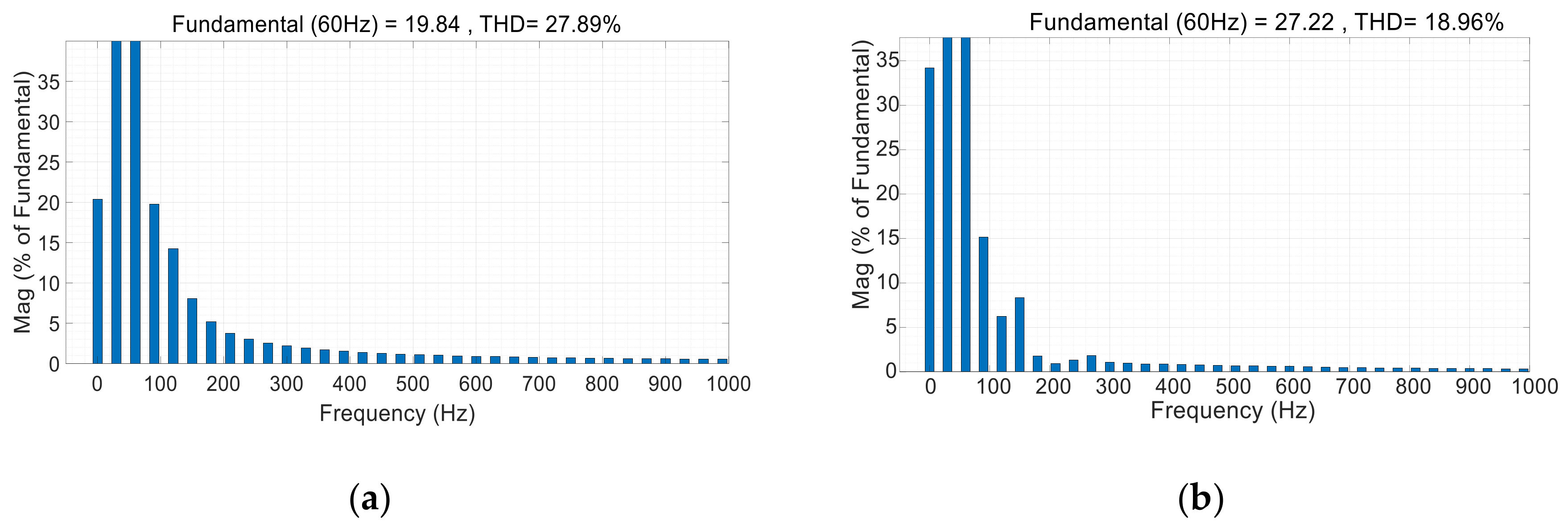
Figure 11 and
Figure 12, respectively, show the comparison of torque, speed, and harmonics of different inverters under PI control. The rated speed of PMSM is set to 1000 r/min, and the load torque when the motor is started is 5 N·m. At 0.5 s, the motor load suddenly increases to 10 N·m; at 1 s, the motor load suddenly decreases to 5 N·m.
Figure 11 shows that the torque ripple and speed ripple of the PMSM controlled by the three-phase four-bridge inverter are lower than those of the motor controlled by the three-phase inverter.
Figure 12 shows that the current harmonic distortion rate of the three-phase four-bridge control PMSM is 27.89%, which is lower than the total A-phase harmonic distortion rate of the traditional three-phase inverter of 18.96%.
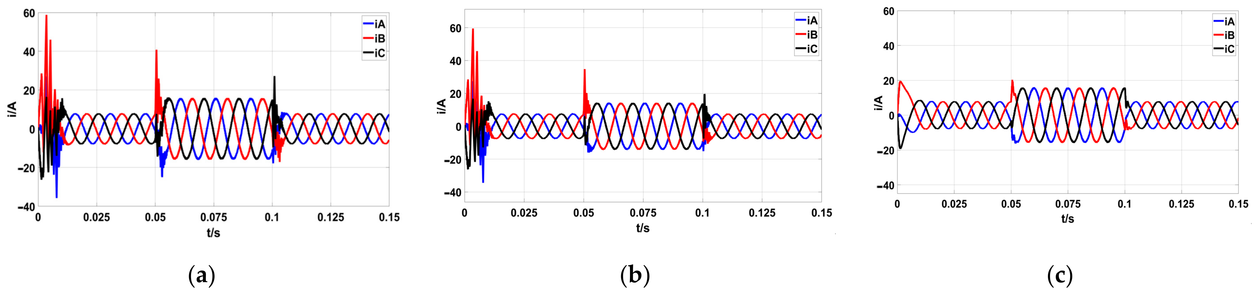
The simulation of PMSM under ADRC, improved ADRC, and fuzzy-ADRC is carried out. The given speed is 1000 r/min, and the load torque when the motor starts is 5 N·m. At 0.05 s, the motor load suddenly increases to 10 N·m, and at 0.1 s, the motor load suddenly decreases to 5 N·m.
Figure 13,
Figure 14 and
Figure 15 are the simulation results.
From
Figure 13, we can see that the PMSM’s starting torque under fuzzy-ADRC and the torque under sudden load change are lower than those under improved ADRC, and the motor torque pulsation under improved ADRC is lower than that under active disturbance rejection control. By comparing
Figure 14, it can be seen that the speed pulsation of the PMSM under fuzzy-ADRC is lower than that under improved ADRC, while the speed pulsation under improved ADRC is lower than that under ADRC. From
Figure 15, we can see that the PMSM under fuzzy-ADRC has the lowest current pulsation and the shortest recovery time.
In order to make the PMSM stop at the specified position quickly and stably, the initial position of the motor was set to 30 rad in the system for the three closed-loop control modes, and the load of PMSM changed from 5 N·m to 10 N·m after 1 s. The rotor position of PMSM under ADRC, improved ADRC, and fuzzy-ADRC were simulated, and the simulation comparison diagram is shown in
Figure 16 and
Figure 17.
Via a comparative analysis of
Figure 16 and
Figure 17, it can be seen that when the given rotor position is 30 rad, under ADRC, improved ADRC, and fuzzy-ADRC, the rotor position fluctuation of the motor under ADRC is largest when the motor load changes abruptly. The position fluctuation of the motor rotor under the improved ADRC is less than that under ADRC, and the time to return to the predetermined position is shorter. The position of the motor rotor under fuzzy-ADRC comprises basically no pulsation, and its stability is the best.
Via the above simulation experiments and analysis, it can be seen that the three-phase four-bridge PMSM can effectively suppress the torque, speed, and current ripple of the motor under fuzzy-ADRC. This control method can maintain safe and stable operation of the motor regardless of whether the motor starts with load or the load changes during operation. This greatly improves the safety and stability of the motor operation and meets the requirements of the aviation electromechanical actuator for the motor.


