Article

Nonlinear Capacitance Compensation Method for Integrating a Metal–Semiconductor–Metal Varactor with a Gallium Nitride High Electron Mobility Transistor Power Amplifier

1
School of Information Science and Technology, ShanghaiTech University, Shanghai 201210, China
2
Shanghai Institute of Microsystem and Information Technology, Chinese Academy of Sciences, Shanghai 200050, China
3
University of Chinese Academy of Sciences, Beijing 100049, China
*
Author to whom correspondence should be addressed.
Electronics 2024, 13(7), 1265; https://doi.org/10.3390/electronics13071265
Submission received: 30 January 2024 / Revised: 3 March 2024 / Accepted: 23 March 2024 / Published: 28 March 2024
(This article belongs to the Special Issue Microwave Devices and Their Applications)

Abstract

:
A nonlinear capacitance compensation technique is presented in this paper to enhance the linearity of a power amplifier (PA) in the GaN process. The method involves placing an MSM varactor device alongside the GaN HEMT device, which works as the amplifying unit such that the overall capacitance observed at the amplifier input is constant, thus improving linearity. This approach is a reliable and straightforward way to improve PA linearity in the GaN process. The proof-of-concept prototype in this study involves the fabrication of a PA device using a standard GaN HEMT process, which successfully integrates the proposed compensation technique and demonstrates excellent compatibility with existing processes. The prototype has a saturation output power of 18 dBm, a peak power-added efficiency of 51.8%, and a small signal gain of 15.5 dB at 1 GHz. The measured AM–PM distortion at the 5 dB compression point is reduced by more than 50% compared to that of an uncompensated device. Furthermore, the results of third-order intermodulation distortion demonstrate the effectiveness of the linearity enhancement concept, with values improved by more than 5 dB in the linear region compared to those of the uncompensated device. All of the results demonstrate the potential utility of this design approach for wireless communication applications.

1. Introduction

Gallium nitride (GaN) high electron mobility transistors (HEMTs) have emerged as a highly suitable technology for radio frequency (RF) and microwave PA applications, primarily due to their remarkable power density and efficiency. GaN HEMTs are widely recognized for their good performance in wireless communications and radar systems [1,2,3]. Nonetheless, the nonlinear behavior of GaN PAs has the following unique characteristics: (1) highly nonlinear transconductance and trapping effects lead to soft compression in the AM–AM characteristics, especially for complex modulation signals with high PAPR; (2) unlike silicon LDMOS devices, whose AM–PM distortion is determined by the output nonlinear capacitance, GaN HEMTs are determined by the variation of the input impedance due to the nonlinear gate–source capacitance (Cgs) and the input Miller–reflection gate–drain capacitance (Cds). These properties present new challenges for the linearization of GaN PAs. In such cases, stringent requirements are placed on the amplifier linearity, both for AM–AM and AM–PM.
Several RF PAs have been published that use improved linearization techniques, either digital or analog, to support higher data rates and higher-order modulation signals. Digital predistortion based on baseband signal processing is also used to improve linearity [4]. Although very powerful, digital predistortion algorithms are based on black-box behavior modelling and therefore do not provide designers with circuit-level feedback or solutions. Two general approaches for PA phase linearization have been developed. In one approach, a multi-transistor architecture or combination of nonlinear devices is employed as the power unit, and the nonlinear curves of individual devices are combined to compensate for the nonlinear characteristics of different devices [5]. In another approach, separate nonlinear circuits or cascaded/parallel amplifier stages are used to equalize the phase-power profile [6]. The first approach is aimed at optimizing the efficiency and bandwidth, with little consideration of linearity. Moreover, the second approach can be influenced by matching network effects, linearizer losses, and PM variations [7]. In CMOS PAs, the nonlinear input capacitance of NMOS transistors can be mitigated by introducing auxiliary PMOS transistors as varactors, which have complementary input capacitance characteristics [8]. The broadband compensation capability of this ultrawideband technology has been experimentally demonstrated [9]. However, this technique is impractical in GaN processes, as only N-channel transistors are available.
In this paper, we propose a method to compensate for the input capacitance of GaN-based PAs by leveraging the nonlinearity of Metal–Semiconductor–Metal (MSM) varactors. To validate the effectiveness of the proposed approach, we fabricate a prototype amplifier based on a theoretical design using a standard III–V process. Through small-signal tests, we observe a significant reduction in the variation in the input capacitance of the compensated device from 251 fF to 122 fF. This work demonstrates the successful compensation achieved by this method. Furthermore, single-tone and two-tone tests are conducted to evaluate the AM–PM characteristics and linearity of the compensated amplifier. The results illustrate the excellent AM–PM characteristics and high linearity of the proposed device, indicating the efficacy of our compensation method. This method offers a novel approach for designing high-linearity PAs that are fully compatible with current processes. This approach holds promise for the design of GaN-based MMICs and high-power PAs.

2. The Nonlinearity Generated by the Input Capacitance

The Class-AB PA typically operates near the threshold voltage of the transistor device. When subjected to a large input signal, the device swiftly alternates between the on and off states, leading to a substantial alteration in the gate-to-source capacitance (Cgs) [10]. This effect is further amplified when large transistors are used to increase the output power.
To gain insight into the nonlinearity in GaN HEMTs, a simplified, nonlinear model is presented in Figure 1. Figure 1 illustrates the major nonlinear sources in a GaN transistor and their interdependencies: the drain-to-source current (Ids), the Cgs, and the Cgd. An analysis of Figure 1 allows us to determine the input capacitance (Cin). Cgs is connected to the ground, while Cgd exists between the input and output of the device. Therefore, the capacitance observed from the gate to the ground is the sum of Cgs and the Miller multiplication of Cgd, which can be expressed as:
C i n v g s = C g s v g s + ( 1 A v v g s ) C g d ,
where A v is the voltage gain of the PA and is defined as Av = −gmZL and ZL is the load impedance of HEMT. The complex input impedance, represented as Zin, is observed from the gate (G).
Z i n v g s = 1 j ω C i n v g s ,
The variation in Zin() with respect to the input amplitude results in AM–PM distortion. This distortion is exclusively caused by nonlinear capacitors and is observed in the gate voltage and subsequently in the drain current.
As shown in Equation (1), the Cgs and gm will not have linear behavior due to their dependence on vgs. Hence, Zin will not be constant during large-signal operation and cause nonlinearity [11]. In Equation (1), Cgs is the small-signal capacitance of the nonlinear capacitor. In small-signal operation, a certain phase shift appears from the input port to the gate of the GaN HEMT, but as the input amplitude rises, the effective Cin changes and so does this phase shift. The changing phase shift with input amplitude gives rise to AM–PM distortion. The Cgd contribution is due to AM–AM gain variation, that is, to gain compression. As voltage gain A v drops, the Miller-multiplied capacitance diminishes, resulting in the AM–PM distortion, like Cgs. The nonlinear input capacitance’s impact on AM–AM characteristics is minor, as the design frequency is less than the cut-off frequency of the input RC impedance [12].
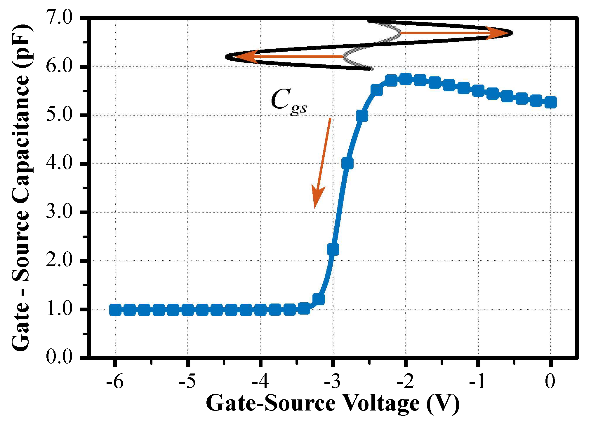
For a 10 W GaN HEMT device, the strongly nonlinear CV profile of the Cgs is depicted in Figure 2. The average input capacitance of a transistor is subjected to the gate bias condition and input signal magnitude. As shown in Figure 2, the GaN HEMT is biased in the Class-AB mode. For small-to-large input swings, the average Cgs of the HEMT is reduced, which is supposed to result in AM–PM distortion.

3. Proposed Capacitance Compensation Method

To enhance the linearity characteristics of GaN PAs, AM–PM distortion can be mitigated by reducing the variation in the input capacitance. The input capacitance–compensation technique is widely use to improved linearity in CMOS PA [8]. However, this compensation technique is not effective in GaN processes, as only N-channel transistors are available.
The implementation of this idea can be achieved through the use of an MSM varactor, which has the potential to be integrated with GaN devices [13]. The MSM varactor is composed of two Schottky diodes with back-to-back contacts, as shown in Figure 3. By adjusting the electrode geometry, the capacitance swing of the MSM varactor can be altered [14]. In the unbiased state, the capacitance of the MSM varactor is determined by the electrode area and the distance to the 2DEG channel, which acts as an equipotential plane. When applying a bias voltage, depletion occurs in the channel beneath the reverse-biased electrode. As the bias voltage increases, the depletion region extends deeper into the device, resulting in a significant reduction in capacitance within a narrow voltage range [13]. The transition voltage, which is closely related to the threshold voltage of the corresponding transistor, varies depending on the carrier density of the 2DEG. It facilitates the transition from high to low capacitance. The transition voltage is the threshold voltage of the reverse-biased contact added by the voltage drop at the forward-biased contact. When the MSM varactor and HEMT are integrated on the same epitaxial wafer, the trends of the nonlinear capacitance in both components exhibit similarities. The absence of P-type devices in the GaN process can also be overcome. This characteristic allows for the compensation of the input capacitance of the HEMT using the MSM varactor, which is similar to the approach applied in CMOS processes [8].
The nonlinear Cgs-Vgs profile can be modeled as a tangent function, which is an anti-symmetric function for the center point V0. As shown in Figure 3, suppose the HEMT Cgs-Vgs profile is modeled as
C g s ( v ) = C 0 + C 1 · t a n h ( v V 0 V 1 ) ,
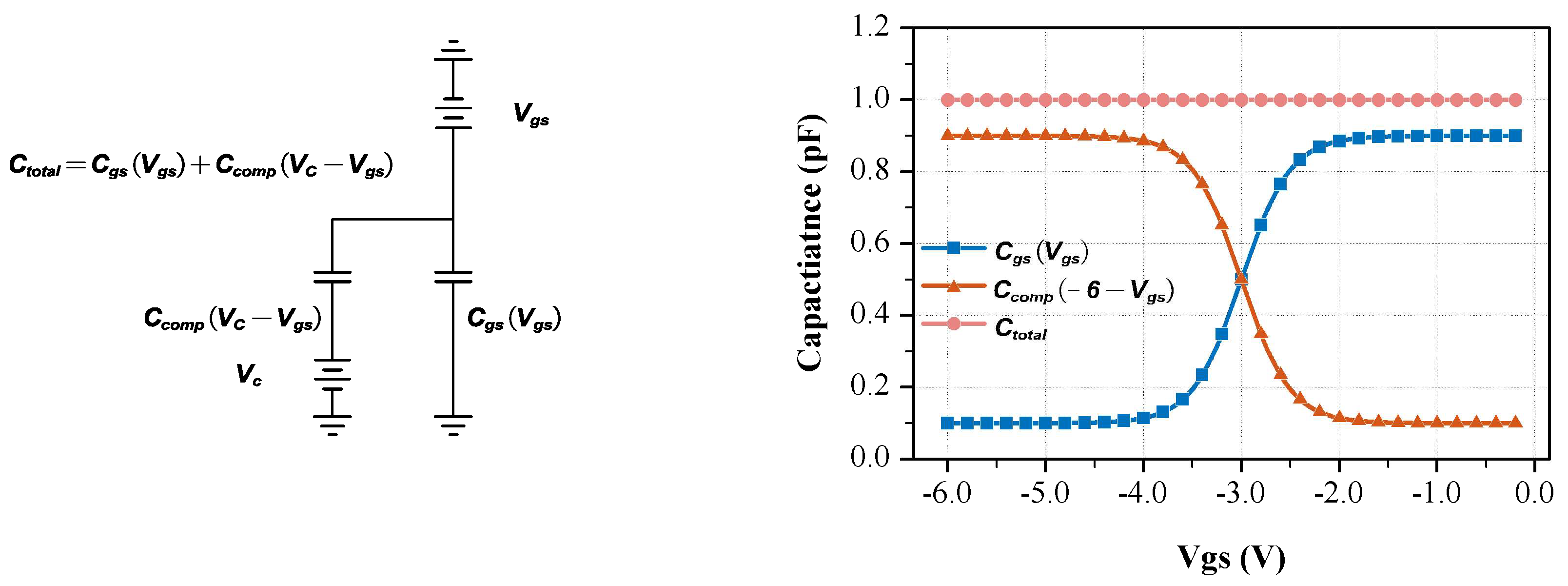
Figure 4 illustrates that by adding an ideal nonlinear compensating capacitor (Ccomp) in parallel with the Cgs, the overall input capacitance can be maintained constant, unaffected by the Vgs. This concept can be realized by integrating an MSM varactor at the input of HEMT. The MSM varactor is biased at control voltage (Vc), which is derived from the sum of the V0 of HEMT Cgs and the threshold voltage of the MSM varactor. Consequently, this compensatory arrangement reduces the AM–PM distortion resulting from the nonlinear input capacitance. However, compensating for the varactor increases the chip area due to the large size of the PA HEMT and an increase in the input capacitance.

4. Implementation

4.1. Fabrication

The device proposed in this study was fabricated on a 6 inch Si substrate through metal–organic chemical vapor deposition (MOCVD) and consisted of a 3 μm thick buffer layer, a 200 nm undoped GaN channel layer, a 1 nm AlN spacer layer, a 25 nm undoped Al0.25Ga0.75N layer, and a 3 nm GaN cap layer. The MSM varactors were co-fabricated alongside transistor devices, demonstrating their compatibility with HEMT technology. The devices were first processed with mesa insulation through Cl-based plasma etching, followed by a 60 °C TMAH surface pretreatment process to reduce GaN surface damage due to plasma etching and to achieve a better surface state [15]. Ohmic contacts were formed by annealing 20/50/150/80 nm Ti/Al/Ni/Au at 850 °C in N2 for 45 s. A pre-gate, two-step treatment consisting of 1 min of low-power O2 plasma and HCl wet etching was repeated three times to reduce the leakage current [16], followed by 20/200 nm Ni/Au gate metallization, 200 nm SiNx passivation layer deposition through plasma-enhanced chemical vapor deposition (PECVD), and contact pad deposition. A multiple-finger MSM varactor structure was employed in this study to mitigate the transmission line effect arising from the use of metal pads [17].

4.2. Device Design

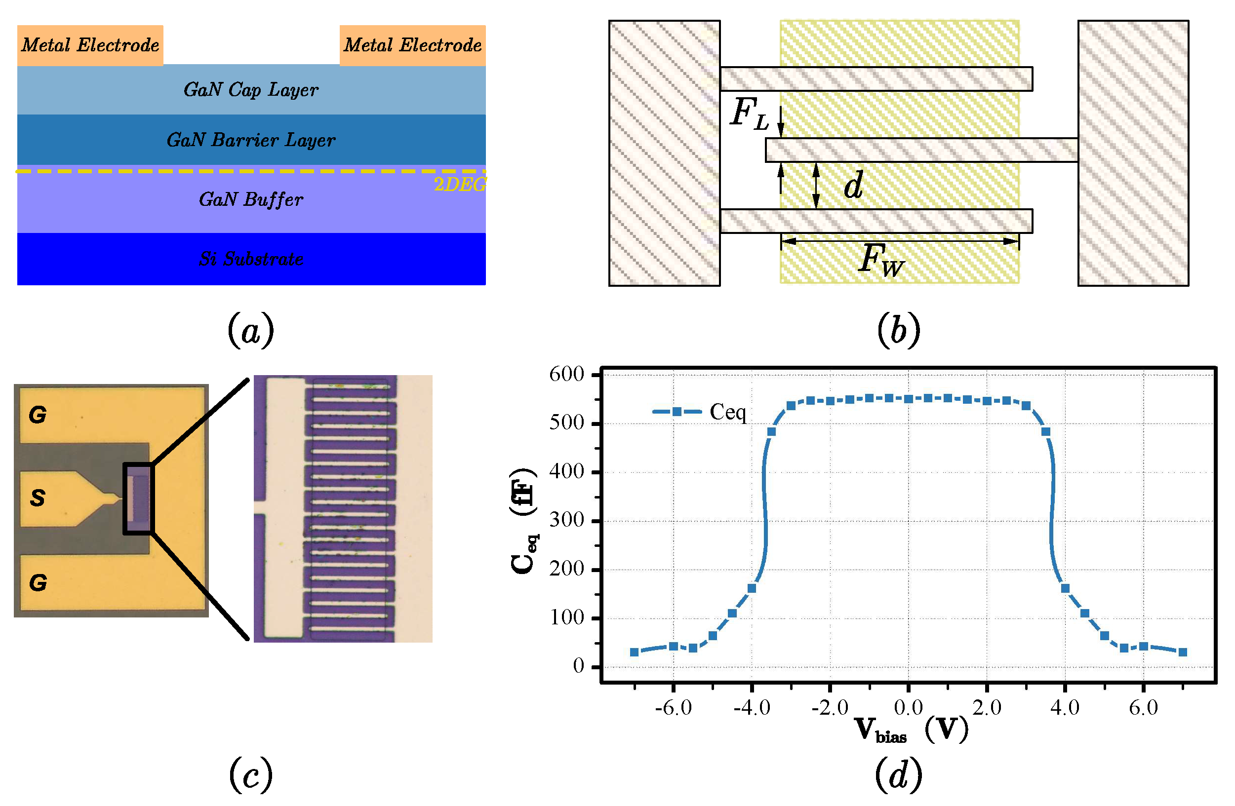
The MSM varactor, as shown in Figure 5, consists of two electrodes deposited on top of an AlGaN/GaN structure. The fabricated MSM varactors are single-end devices with a G-S-G pad. The dimensions of the varactors can be described by four parameters, including the finger length (FL), the finger width (Fw), the finger-to-finger spacing (d), and the number of fingers (N), as illustrated in Figure 5. A microphotograph of a fabricated MSM varactor is displayed in Figure 5.
The capacitance–voltage (C-V) characteristics are obtained using one-port S-parameter measurements up to 10 GHz obtained using a vector network analyzer (VNA). The measurements can be accurately fitted to a conventional varactor equivalent circuit with capacitance (CMSM), parallel conductance (GMSM), series resistance (RMSM), and inductance (LMSM) for frequencies within the measurement frequency range. This equivalent circuit is valid for the investigated electrode layouts across the entire measurement frequency range. Figure 5d illustrates the C-V characteristics of the MSM varactor. As shown in Figure 6a, Equation (3) is used to fit the equivalent capacitance of the reverse-biased MSM varactor, where V0 is −3.7 V and V1 is 0.4 V.
Notably, the HEMT and MSM varactor both exhibit staircase patterns in terms of their C-V characteristics, as depicted in Figure 6. Specifically, Figure 6b highlights the behavior of the HEMT, and Equation (3) is used to fit the Cgs of the HEMT, where V0 is −3 V and V1 is 0.6 V.
As the compensated device, the capacitance of the unbiased MSM varactor should equal the maximum Cgs value of the device being compensated for. As shown in Figure 3b, the Cgs value of the GaN HEMT can be considered the depletion capacitance beneath the gate:
C g s = ε A G ( 1 d + 1 d 2 D E G ) ,
As shown in Figure 3a, the capacitance of the MSM varactor is given by [18]:
C M S M = 1 2 ε A M S M 1 d + 1 d 2 D E G ,
where d is the depth of the depletion region beneath the electrode influenced by the applied bias voltage, d2DEG is the distance of the electrode to the 2DEG, AG is the gate area of the HEMT, and AMSM is the electrode area of MSM varactor. Within the same epitaxial layer and fabrication process, both d and d2DEG are constants. To realize a linear input capacitance, the maximum capacitance of the MSM varactor and HEMT must be equal. Consequently, the electrode area of the MSM varactor produced with the same fabrication process should be twice the gate area of the HEMT.
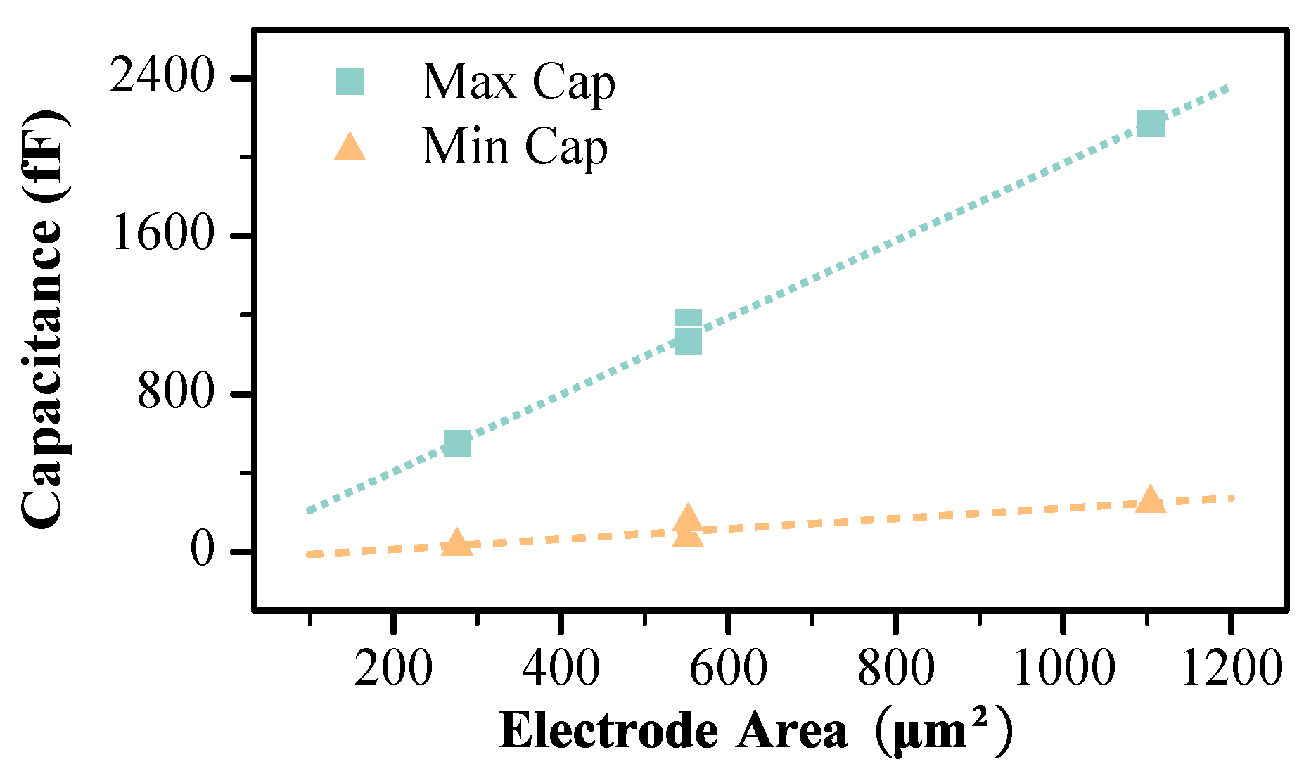
The capacitance swing of the MSM varactor can be changed by manipulating the electrode geometry [14]. This is clearly demonstrated in Table 1 and Figure 7, which reveal the direct relationship between the capacitance of the MSM varactor and the electrode area (N*Fw*FL). By appropriately adjusting the electrode area, the capacitance can be precisely controlled, allowing specific compensation requirements to be fulfilled.
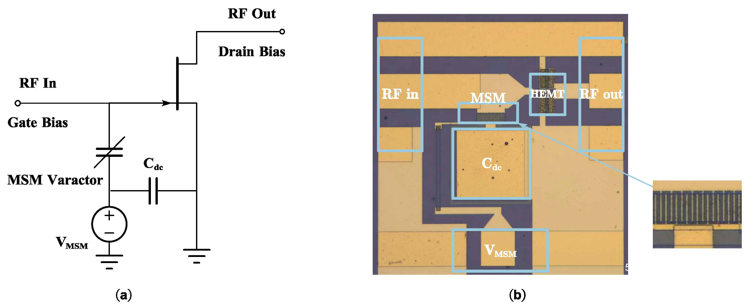
Considering the distinct variations in the capacitance of the HEMT and MSM varactor at their respective bias voltages, the bias voltage (VMSM) of the MSM varactor, as shown in Figure 8a, needs to be set as
V M S M = V 0 H E M T + V 0 M S M
In the prototype, the HEMT gate length is 1.2 μm, and the width is 100 μm, while the connected MSM varactor includes an electrode with a width of 23 μm and a length of 1.2 μm and eight fingers. The ratio of the HEMT gate area to the MSM varactor electrode area is approximately 1:2. A schematic diagram and a microscope diagram are shown in Figure 8. Based on the test results depicted in Figure 6, the V0 of the fabricated GaN HEMT and MSM varactor, Cgs, is estimated to be approximately −3 V, while the switching voltage of the MSM varactor is approximately −3.7 V. Therefore, the VMSM should be adjusted to −6.7 V.

5. Measurement Results

In this section, the measurement results are presented to evaluate the effectiveness of the proposed compensation technique using MSM varactors to enhance the linearity of GaN HEMT PAs.

5.1. Small-Signal Measurements

The small signals of both the compensated and uncompensated devices were assessed using a VNA. The input capacitance is extracted from the small-signal S-parameters, which are measured under varied gate bias and a fixed drain bias of 12 V. Figure 9 shows a plot of the Port1-to-ground capacitance for both the compensated and uncompensated devices, obtained by calculating Im{y11y21}/ω. The difference in the maximum and minimum capacitance values of the fabricated prototype was significantly reduced, decreasing from 251 fF to 122 fF. The interdigital electrode structure of the MSM varactor caused parasitic capacitance, resulting in a capacitance difference of 122 fF. This result shows a substantial decrease in the overall capacitance variation at the amplifier’s input after implementing the compensation technique involving MSM varactors.

5.2. Single-Tone RF Power Measurement

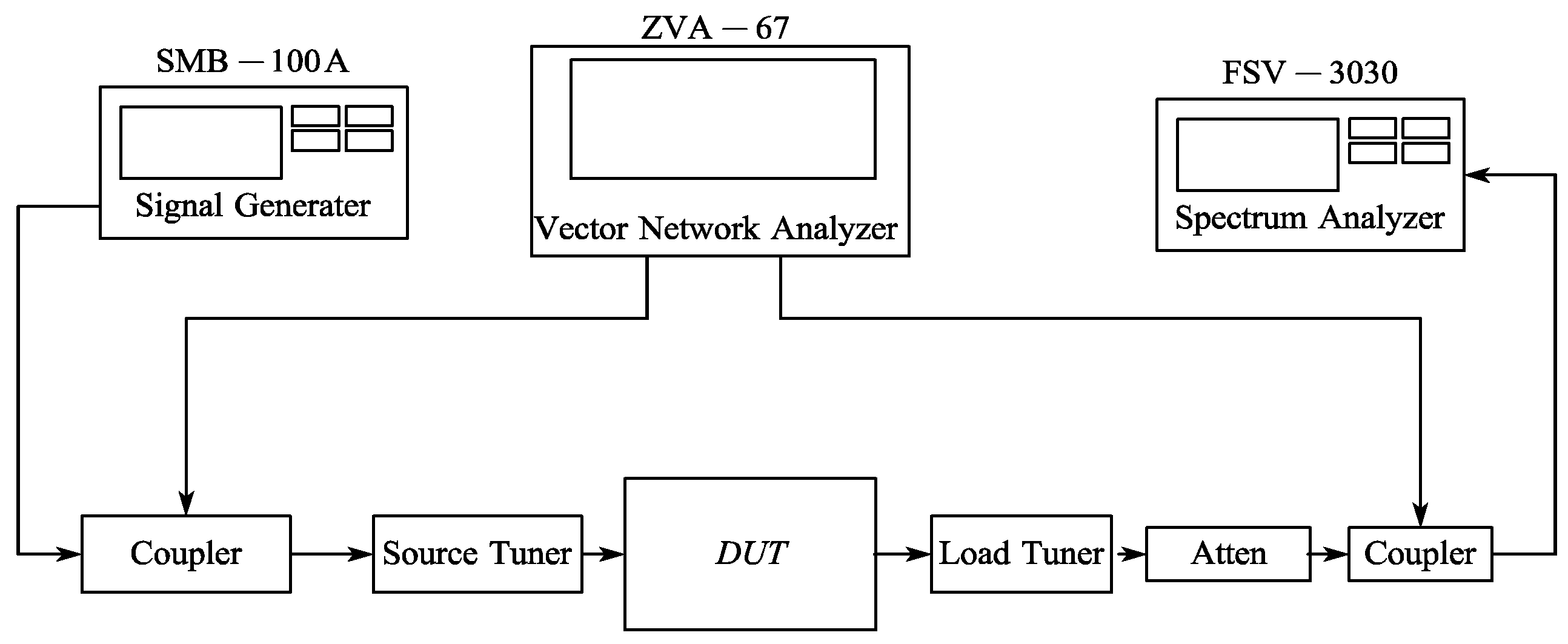
The RF power characteristics of the device were measured using a load-pull measurement system. The experimental setup for the CW measurements is shown in Figure 10. The CW input signal is generated by a signal source (R&S SMB-100A). The bias point selection aims to minimize changes in the source impedance of the load-pull system during the test and eliminate the influence of the source impedance on the AM–PM results. The same load impedance (Gamma = 0.782, Phase = 2 deg) and source impedance (Gamma = 0.671, Phase = 21.5 deg) values were used in all tests. The source impedance is chosen to balance the gain of both devices, and the load impedance is the maximum of the output power. The PA output is monitored by a VNA and Spectrum Analyzer to test the PA gain/power response and AM–PM distortion. Figure 10 presents the single-tone power characteristics for both the compensated and uncompensated devices at a frequency of 1 GHz, with Vd = 12 V and Vgs = −2 V, where Id = 20% of Idss. The compatibility of the HEMT with a range of bias voltages was examined by evaluating adjacent bias points within the ±0.1 V range. The test results demonstrate the effectiveness of this compensation within the appropriate bias voltage range.
PAs are first characterized using CW signals. The saturated output power (Psat), power-added efficiency (PAE), gain, and AM–PM distortion are measured under the same load impedance (Gamma = 0.782, Phase = 2 deg) and source impedance (Gamma = 0.671, Phase = 21.5 deg).
Figure 11 shows the measured gain and power-added efficiency (PAE) of the two devices. As it can be seen, the uncompensated device achieves a small signal gain of 15.5 dB and a peak PAE of 49.7% at the output power of 18 dBm; the compensated device achieves similar PAE performance but with a gain that is 0.2 dB lower than the uncompensated device. This reduced gain is attributed to the increased input capacitance associated with the compensation scheme. The output power and PAE at the 3 dB compression point for the uncompensated and compensated devices are 43.9% at 15.3 dBm and 44.6% at 15.2 dBm, respectively.
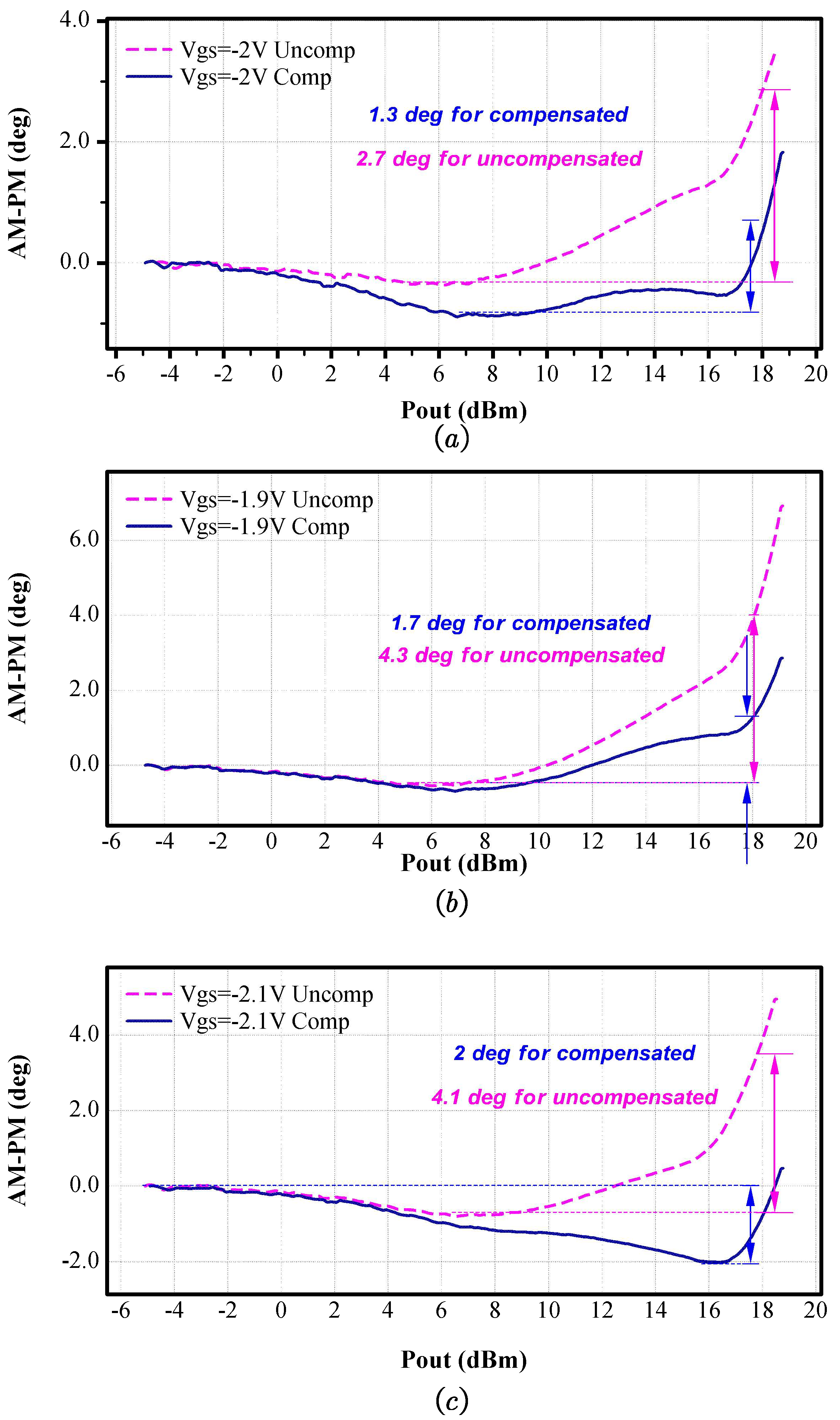
Figure 12a illustrates the AM–PM of the compensated and uncompensated devices at 1 GHz with Vgs = −2 V. The compensated device exhibits an AM–PM distortion of less than 1.3 degrees up to an output power of 18 dBm (approximately 5 dB compression point). On the other hand, the uncompensated device shows an AM–PM distortion exceeding 2.7 degrees at the same output power. As shown in Figure 11, the impact on the AM–AM conversion is minor because the frequency is much lower than the cut-off frequency of the input RC network [19].
Figure 12b,c demonstrate the impact of the proposed compensation scheme on AM–PM distortion. For the compensated device, at −1.9 V Vgs, the AM–PM distortion is reduced to 1.7 degrees, and at −2.1 V Vgs, the AM–PM distortion is only 2 degrees. Conversely, the uncompensated device exhibits AM–PM distortions of 4.3 degrees and 4.1 degrees at the same gate–source voltages. Thus, the input capacitance compensation scheme significantly reduces AM–PM distortion. Despite the application of compensation techniques, importantly, AM–PM distortion persists and is not eliminated. This residual distortion can be attributed to other nonlinear components, including Cgd and nonlinear gm.

5.3. Two-Tone Measurement

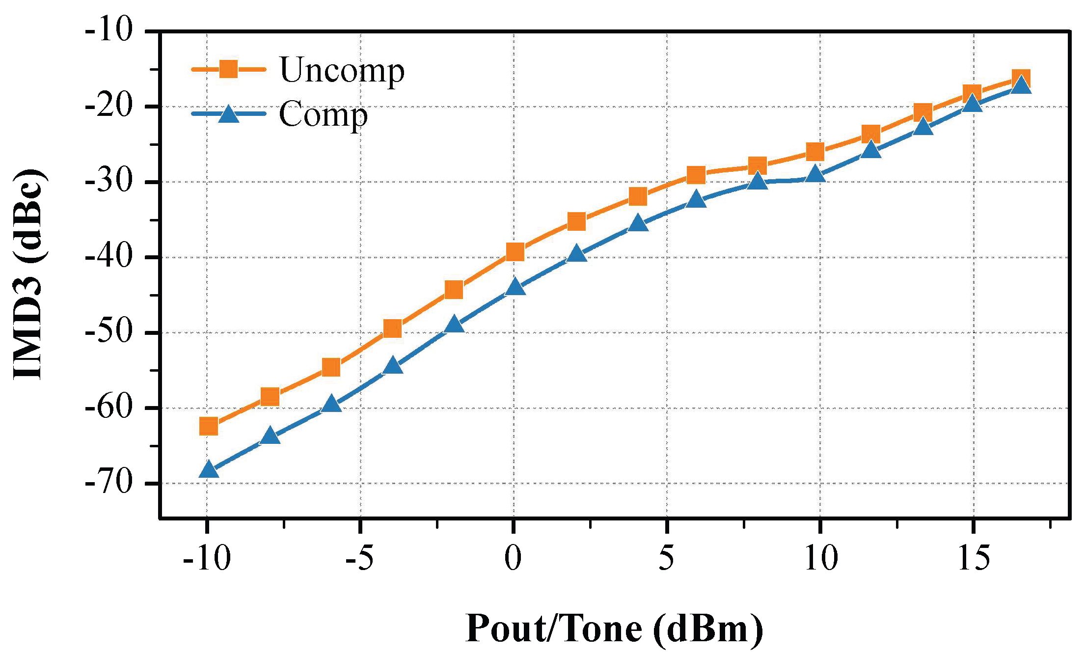
To verify the linearity of the performance, the device was tested under a fixed bias and various input powers using a two-tone signal. The two-tone measurement is performed at a fundamental frequency (f0) of 1 GHz, with a spacing of 10 MHz (Δf), using the same bias conditions as in the single-tone measurement (Vgs = −2 V and Vds = 12 V). The results of these measurements are depicted in Figure 13. Figure 13 reveals a notable improvement of at least 3 dB when the output power is less than 12 dBm in each tone and 5 dB in the small-signal region. AM to PM distortion effects can contribute significantly to IM products in the pre-compression zone, and AM–AM dominates IMD3 distortion when gain compression is increased [9]. This improvement in the pre-compression area highlights the enhanced linearity and reduced distortion of the proposed device when presented with modulation signals.

6. Conclusions

This study presents a nonlinear capacitance compensation technique to enhance the linearity of GaN HEMT PAs. By reducing the overall capacitance variation at the amplifier input, the AM–PM linearity was improved. The experimental results obtained with a prototype amplifier developed utilizing a standard GaN HEMT process and implementing the proposed technique demonstrated linear enhancements in both two-tone IMD3 and AM–PM conversion. This study provides new linearization tools for GaN-based PAs. These results suggest the novelty of the proposed approach for achieving input capacitance compensation in GaN PAs, allowing convenient integration into GaN processes. The potential of the MSM varactor has been extensively investigated, revealing novel possibilities for its utilization in high-linear amplifiers. This advancement offers substantial benefits that facilitate its extensive integration into wireless communication systems and radar systems.

Author Contributions

Conceptualization, K.L., H.G. and X.Z.; methodology, K.L.; software, K.L.; validation, K.L. and H.G.; formal analysis, K.L.; investigation, K.L. and H.G.; resources, K.L. and Y.G.; data curation, K.L.; writing—original draft preparation, K.L.; writing—review and editing, K.L., Y.G. and H.G.; supervision, X.Z.; funding acquisition, X.Z. All authors have read and agreed to the published version of the manuscript.

Funding

This work was supported by ShanghaiTech University Startup Fund 2017F0203-000-14, the National Natural Science Foundation of China (Grant No. 52131303), the Natural Science Foundation of Shanghai (Grant No. 22ZR1442300), and, in part, the CAS Strategic Science and Technology Program under Grant No. XDA18000000. The authors would also to sincerely thank to ShanghaiTech University Platform of Mechatronics, Energy, and Electronic Devices for equipment support.

Data Availability Statement

Data are contained within the article.

Conflicts of Interest

The authors declare no conflicts of interest.

References

  1. Inoue, A. Millimeter-Wave GaN Devices for 5G: Massive MIMO Antenna Arrays for Sub-6-Ghz and Mm-Wave Bandwidth. IEEE Microw. Mag. 2021, 22, 100–110. [Google Scholar] [CrossRef]
  2. Campbell, C.; Lee, C.; Williams, V.; Kao, M.-Y.; Tserng, H.-Q.; Saunier, P.; Balisteri, T. A Wideband Power Amplifier MMIC Utilizing GaN on SiC HEMT Technology. IEEE J. Solid-State Circuits 2009, 44, 2640–2647. [Google Scholar] [CrossRef]
  3. van Heijningen, M.; de Hek, P.; Dourlens, C.; Fellon, P.; Adamiuk, G.; Ayllon, N.; van Vliet, F. C-Band Single-Chip Radar Front-End in AlGaN/GaN Technology. IEEE Trans. Microw. Theory Tech. 2017, 65, 4428–4437. [Google Scholar] [CrossRef]
  4. Mengozzi, M.; Gibiino, G.P.; Angelotti, A.M.; Florian, C.; Santarelli, A. GaN Power Amplifier Digital Predistortion by Multi-Objective Optimization for Maximum RF Output Power. Electronics 2021, 10, 244. [Google Scholar] [CrossRef]
  5. Joo, T.; Koo, B.; Hong, S. A WLAN RF CMOS PA with Large-Signal MGTR Method. IEEE Trans. Microw. Theory Tech. 2013, 61, 1272–1279. [Google Scholar] [CrossRef]
  6. Cai, Q.; Che, W.; Ma, K.; Zhang, M. A Simplified Transistor-Based Analog Predistorter for a GaN Power Amplifier. IEEE Trans. Circuits Syst. II Express Briefs 2018, 65, 326–330. [Google Scholar] [CrossRef]
  7. Lim, K.H.; Ahn, G.; Jung, S.; Park, H.C.; Kim, M.S.; Van, J.H.; Cho, H.; Jeong, J.-H.; Park, C.-S.; Yang, Y. A 60-W Multicarrier WCDMA Power Amplifier Using an RF Predistorter. IEEE Trans. Circuits Syst. II Express Briefs 2009, 56, 265–269. [Google Scholar] [CrossRef]
  8. Wang, C.; Vaidyanathan, M.; Larson, L.E. A Capacitance-Compensation Technique for Improved Linearity in CMOS Class-AB Power Amplifiers. IEEE J. Solid-State Circuits 2004, 39, 1927–1937. [Google Scholar] [CrossRef]
  9. Vigilante, M.; Reynaert, P. A Wideband Class-AB Power Amplifier With 29–57-GHz AM–PM Compensation in 0.9-V 28-Nm Bulk CMOS. IEEE J. Solid-State Circuits 2018, 53, 1288–1301. [Google Scholar] [CrossRef]
  10. Cripps, S.C. RF Power Amplifiers for Wireless Communications; Artech House Publishers: Norwood, MA, USA, 2006. [Google Scholar]
  11. Nunes, L.C.; Cabral, P.M.; Pedro, J.C. AM/AM and AM/PM Distortion Generation Mechanisms in Si LDMOS and GaN HEMT Based RF Power Amplifiers. IEEE Trans. Microw. Theory Tech. 2014, 62, 799–809. [Google Scholar] [CrossRef]
  12. Golara, S.; Moloudi, S.; Abidi, A.A. Processes of AM-PM Distortion in Large-Signal Single-FET Amplifiers. IEEE Trans. Circuits Syst. I Regul. Pap. 2017, 64, 245–260. [Google Scholar] [CrossRef]
  13. Marso, M.; Wolter, M.; Javorka, P.; Fox, A.; Kordoš, P. AlGaN/GaN Varactor Diode for Integration in HEMT Circuits. Electron. Lett. 2001, 37, 1476. [Google Scholar] [CrossRef]
  14. Marso, M.; Fox, A.; Heidelberger, G.; Kordos, P.; Luth, H. Comparison of AlGaN/GaN MSM Varactor Diodes Based on HFET and MOSHFET Layer Structures. IEEE Electron Device Lett. 2006, 27, 945–947. [Google Scholar] [CrossRef]
  15. Yoon, Y.J.; Seo, J.H.; Cho, M.S.; Kang, H.-S.; Won, C.-H.; Kang, I.M.; Lee, J.-H. TMAH-Based Wet Surface Pre-Treatment for Reduction of Leakage Current in AlGaN/GaN MIS-HEMTs. Solid-State Electron. 2016, 124, 54–57. [Google Scholar] [CrossRef]
  16. Lu, X.; Jiang, H.; Liu, C.; Zou, X.; Lau, K.M. Off-State Leakage Current Reduction in AlGaN/GaN High Electron Mobility Transistors by Combining Surface Treatment and Post-Gate Annealing. Semicond. Sci. Technol. 2016, 31, 055019. [Google Scholar] [CrossRef]
  17. San Chu, C.; Zhou, Y.; Chen, K.J.; Lau, K.M. Q-Factor Characterization of RF GaN-Based Metal-Semiconductor-Metal Planar Interdigitated Varactor. IEEE Electron Device Lett. 2005, 26, 432–434. [Google Scholar] [CrossRef]
  18. Hsieh, Y.-L.; Lo, H.-Z.; Nee, T.-E.; Chang, C.-N.; Yang, C.-H. Study on Epitaxial Structure and Substrate Material Variations for Improving Electrical Reliability of the MSM AlGaN/GaN 2DEG Varactors. Microelectron. Reliab. 2023, 142, 114905. [Google Scholar] [CrossRef]
  19. Sarbishaei, H.; Wu, D.Y.-T.; Boumaiza, S. Linearity of GaN HEMT RF Power Amplifiers—A Circuit Perspective. In Proceedings of the 2012 IEEE/MTT-S International Microwave Symposium Digest 2012, Montreal, QC, Canada, 17–22 June 2012. [Google Scholar] [CrossRef]
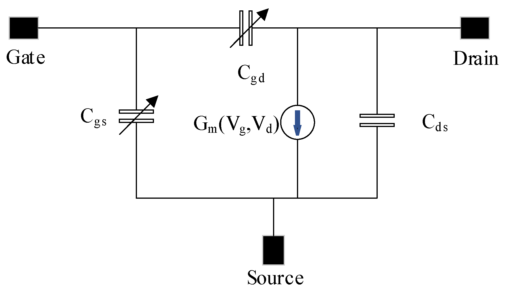
Figure 1. A simplified, nonlinear model for the GaN HEMT.
Electronics 13 01265 g001
Figure 2. Simulation result of the commercial GaN HEMT device’s gate–source capacitance as a function of gate–source voltage for a fixed drain-source voltage of 28 V.
Electronics 13 01265 g002
Figure 3. (a) The proposed MSM varactor structure and equivalent circuit model. (b) Equivalent circuit model for Cgs to HEMT.
Electronics 13 01265 g003
Figure 4. The proposed gate–source capacitance compensation technology for the GaN HEMT. The Cgs is C g s v g s = 0.5 + 0.4 tanh v g s ( 3 ) 0.5 and the compensation capacitance is C c o m p v = 0.5 + 0.4 tanh v ( 3 ) 0.5 . When the MSM varactor is biased to −6 V, Ctotal equals C t o t a l v g s = C g s v g s + C c o m p ( 6 v g s ) = 1.
Electronics 13 01265 g004
Figure 5. (a) The section of the epitaxy of MSM varactor; (b) the physical structure of the MSM varactors; (c) microphotograph of the MSM varactor; (d) the C-V characteristics of the MSM varactor with Fl = 1.2 μm, Fw = 23 μm, d = 3 μm, and N = 10.
Electronics 13 01265 g005
Figure 6. (a) The equivalent C-V characteristics of an MSM varactor with Fl = 1.2 μm, Fw = 23 μm, d = 3 μm, and N = 10. (b) Cgs-Vgs characteristics of the GaN HEMT with a 1.2 µm gate length and a 100 µm gate width.
Electronics 13 01265 g006
Figure 7. Measurement results for electrode area and capacitance characteristics.
Electronics 13 01265 g007
Figure 8. (a) Schematic of the proposed HEMT with a monolithic integrated MSM varactor. (b) Microphotograph of the prototype chip.
Electronics 13 01265 g008
Figure 9. Measurement result of the Port1-to-ground capacitance for both devices.
Electronics 13 01265 g009
Figure 10. CW measurement setup.
Electronics 13 01265 g010
Figure 11. Measurement results for single-tone characteristics.
Electronics 13 01265 g011
Figure 12. Measurement results for AM–PM characteristics at different gate bias (a) Vgs = −2 V (b) Vgs = −1.9 V (c) Vgs = −2.1 V.
Electronics 13 01265 g012
Figure 13. Measurement IMD3 result of the device versus the output power at Vgs = −2 V and Vds = 12 V. The center frequency is 1 GHz for a two-tone spacing of 10 MHz.
Electronics 13 01265 g013
Table 1. Summary of the key properties of the MSM varactor.
NFL (µm)FW (µm)Cmin (fF)Cmax (fF)Cmax/Cmin
101.2233055018.33
101.24674.1116015.65
201.223154.810656.879
201.246246.921708.788
Disclaimer/Publisher’s Note: The statements, opinions and data contained in all publications are solely those of the individual author(s) and contributor(s) and not of MDPI and/or the editor(s). MDPI and/or the editor(s) disclaim responsibility for any injury to people or property resulting from any ideas, methods, instructions or products referred to in the content.