
Design of Universal Code Generator for Multi-Constellation Multi-Frequency GNSS Receiver

 , ,
, ,
Abstract
1. Introduction
2. Introduction to GNSS Spread Spectrum Codes
2.1. Introduction to Spread Spectrum Codes
2.2. Spread Spectrum Code Generation Methods Based on LFSR
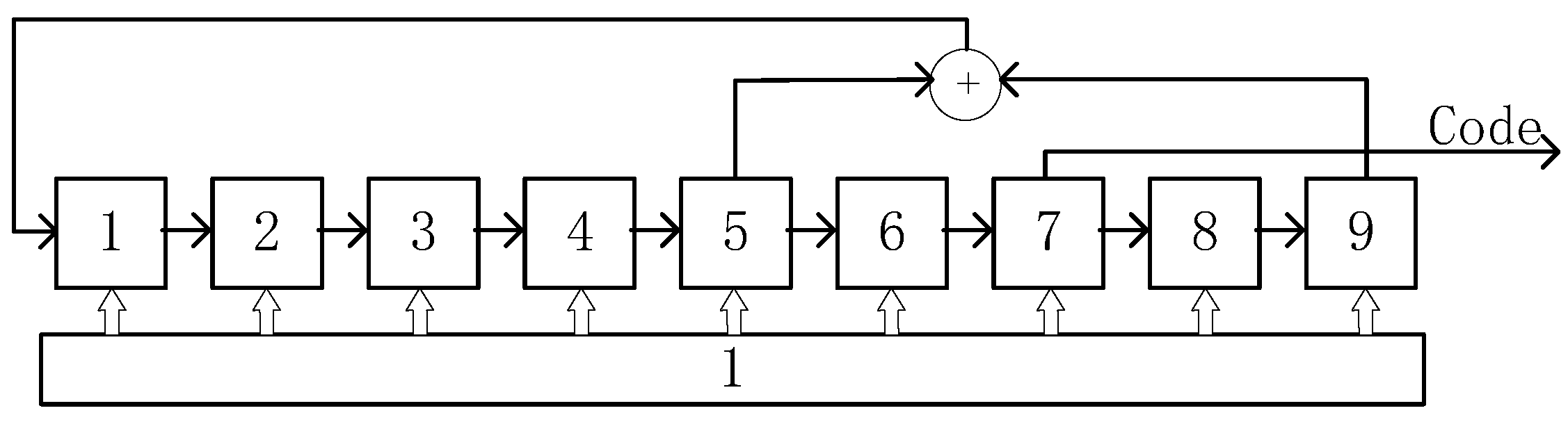
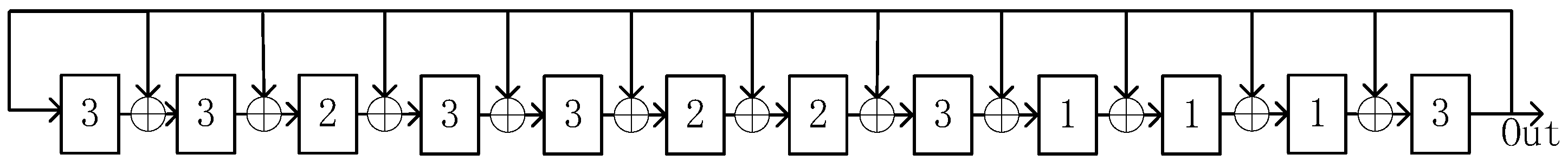
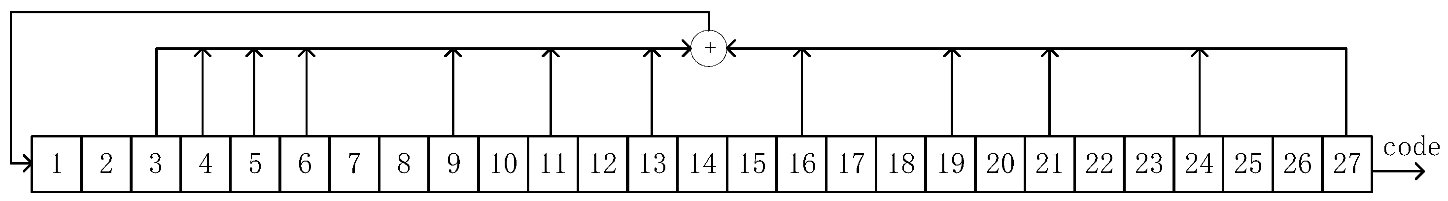
2.2.1. m-Sequence
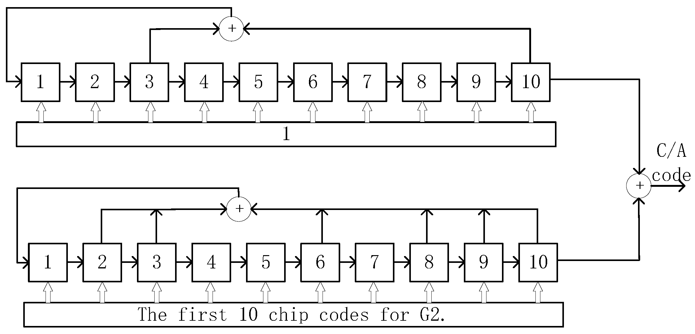
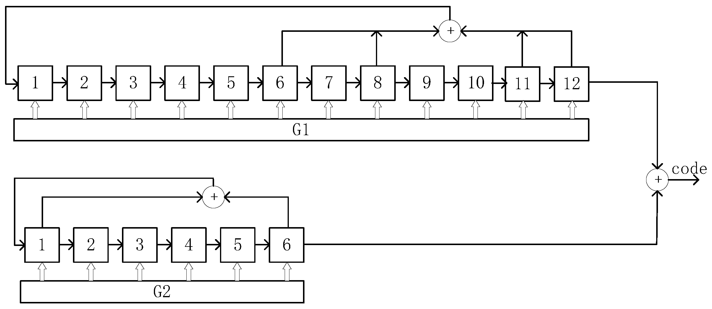
2.2.2. Gold Code
2.2.3. Kasami Code
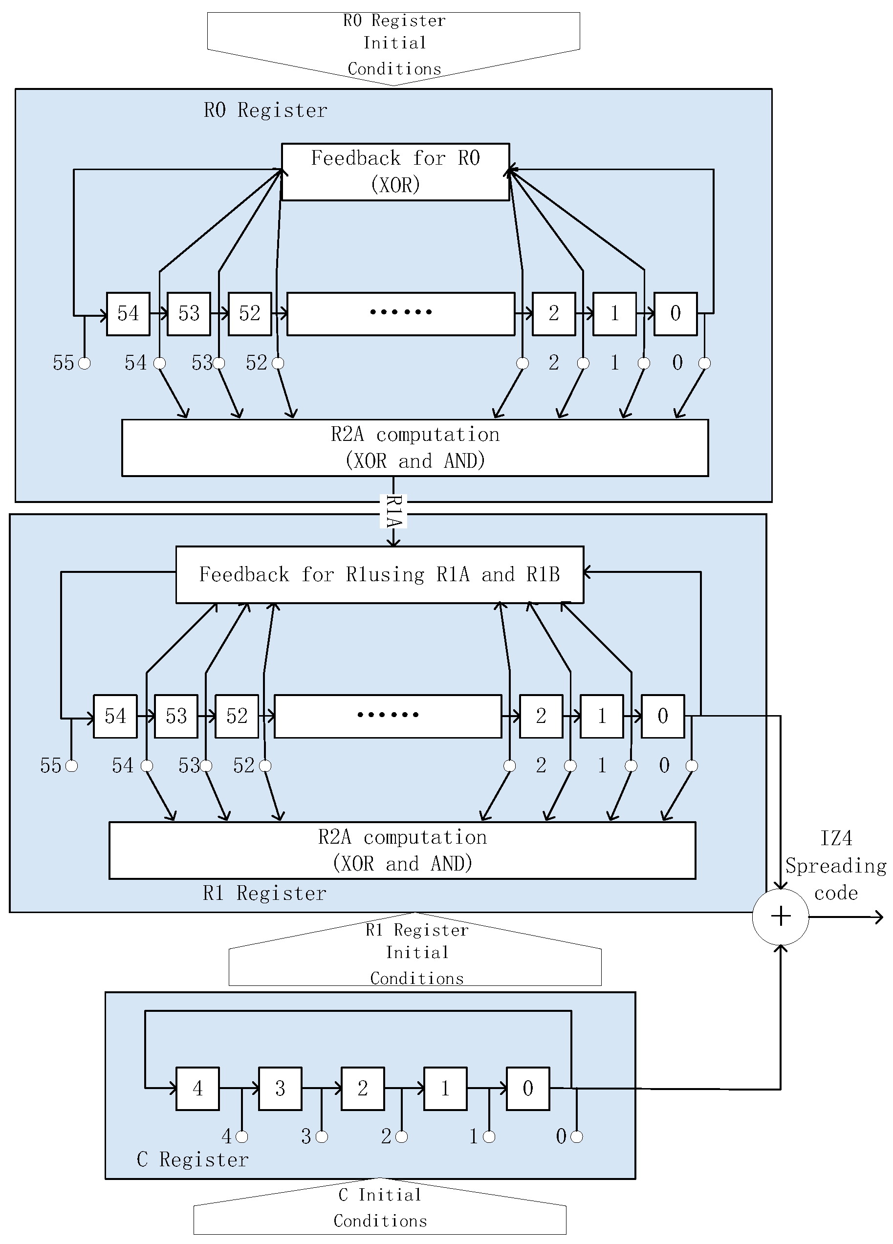
2.2.4. Interleaved Z4-Linear (IZ4) Ranging Code
3. Code Generators
3.1. Universal Code Generators Based on LFSR
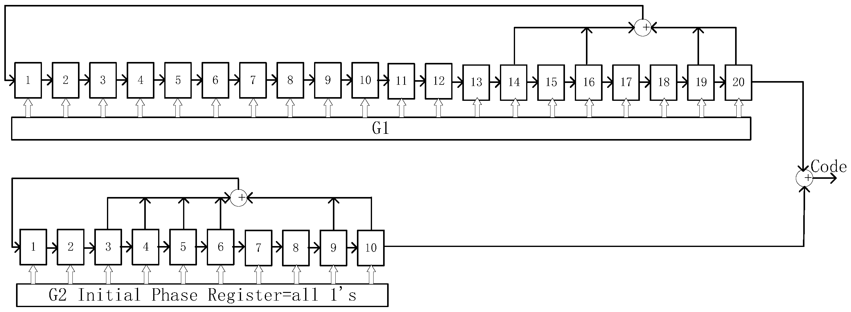
3.1.1. Universal Ranging Code Generator
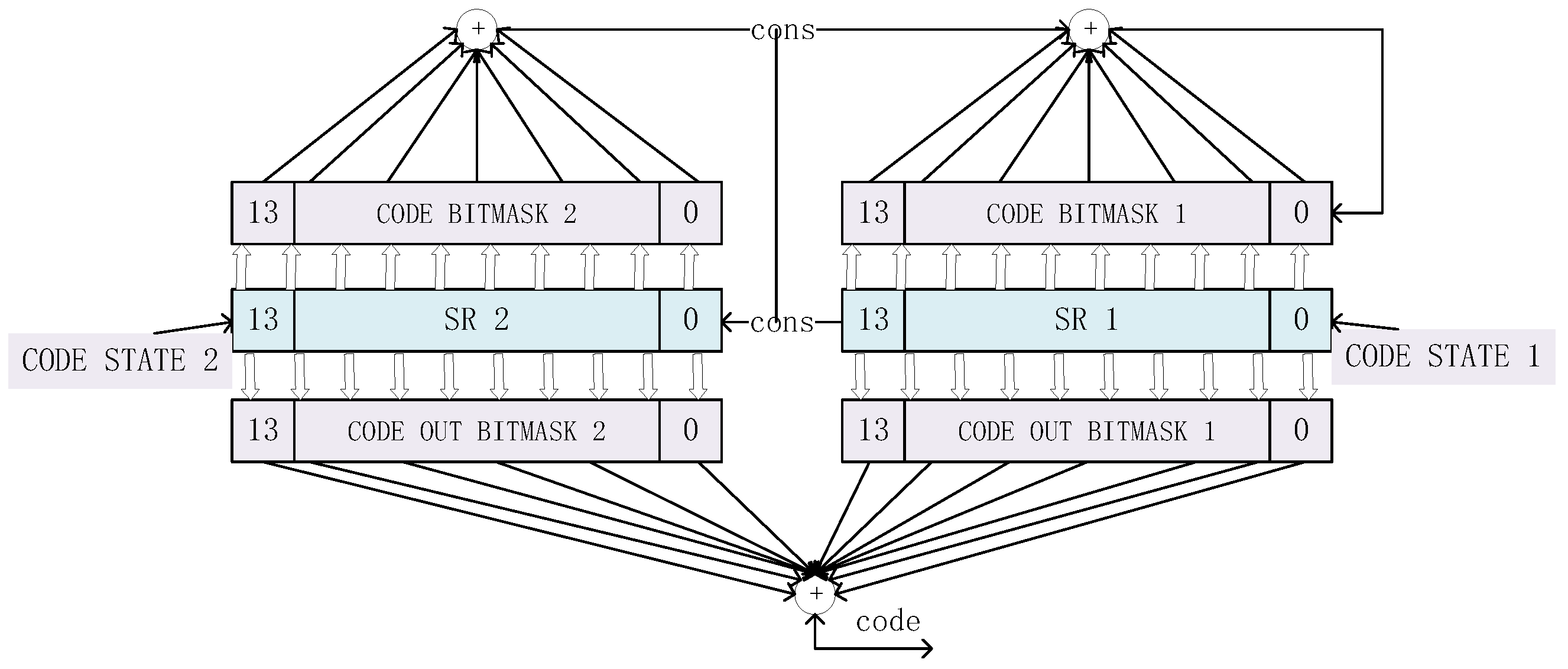
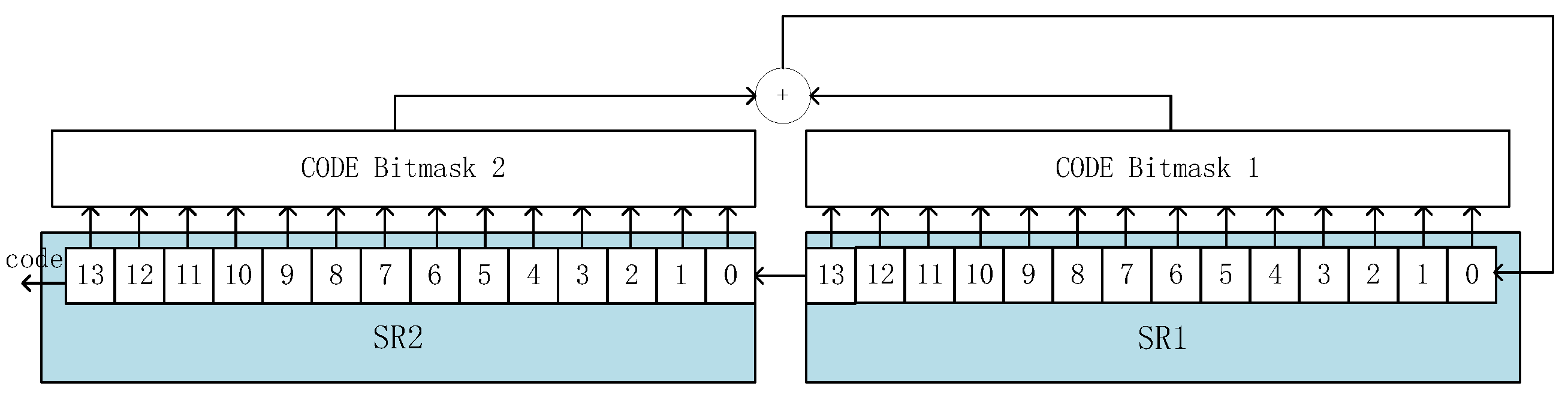
3.1.2. Area-Efficient Universal Code Generator
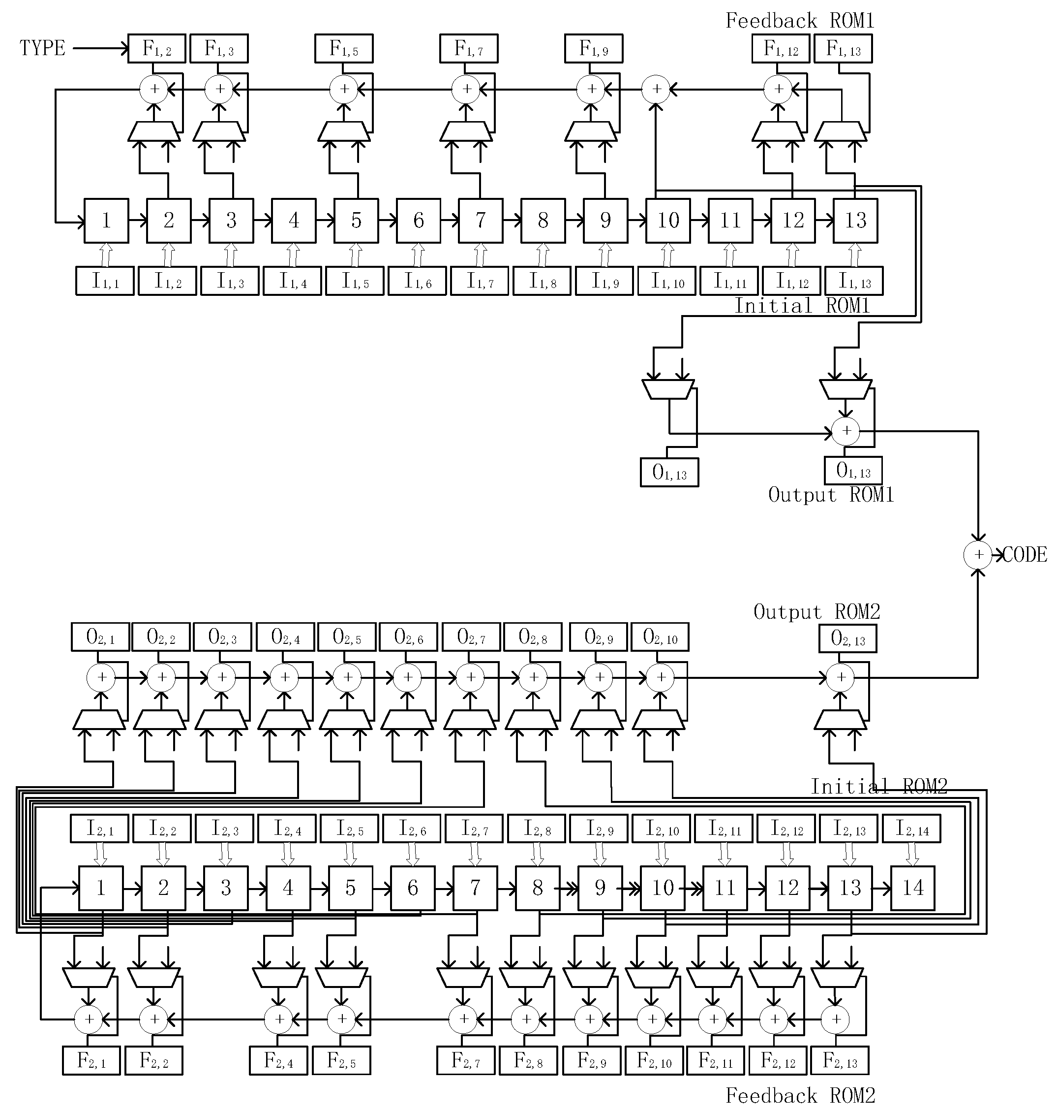
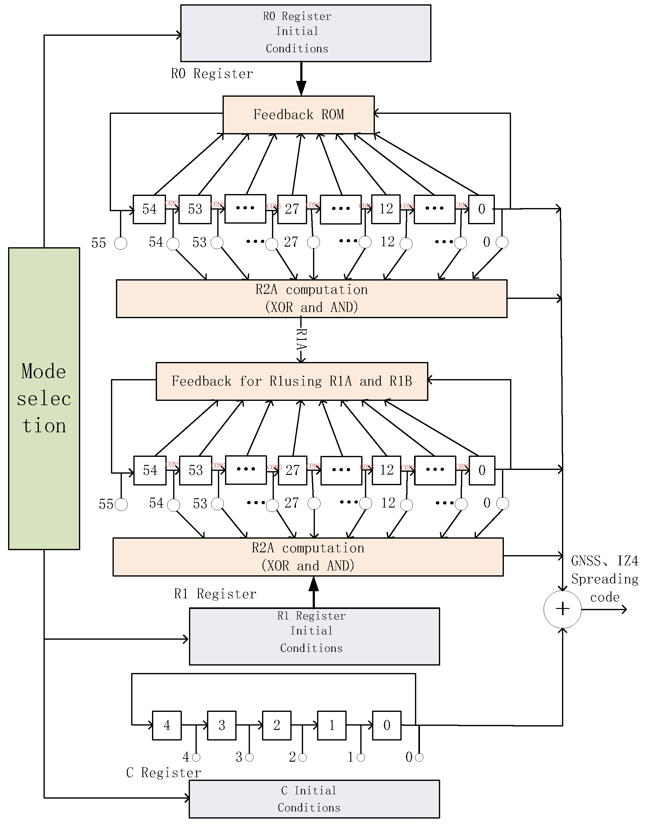
3.2. Proposed Universal Code Generator
4. Experimental Results
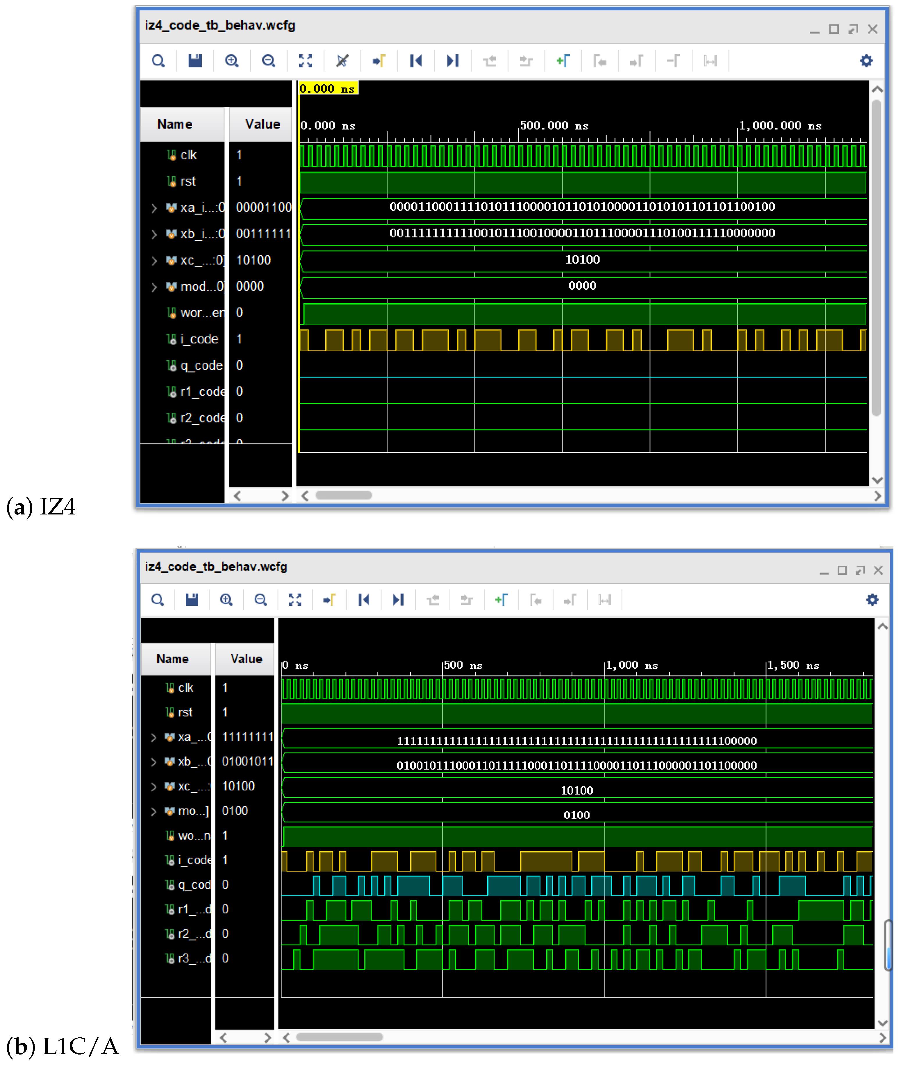
4.1. FPGA Verification Results
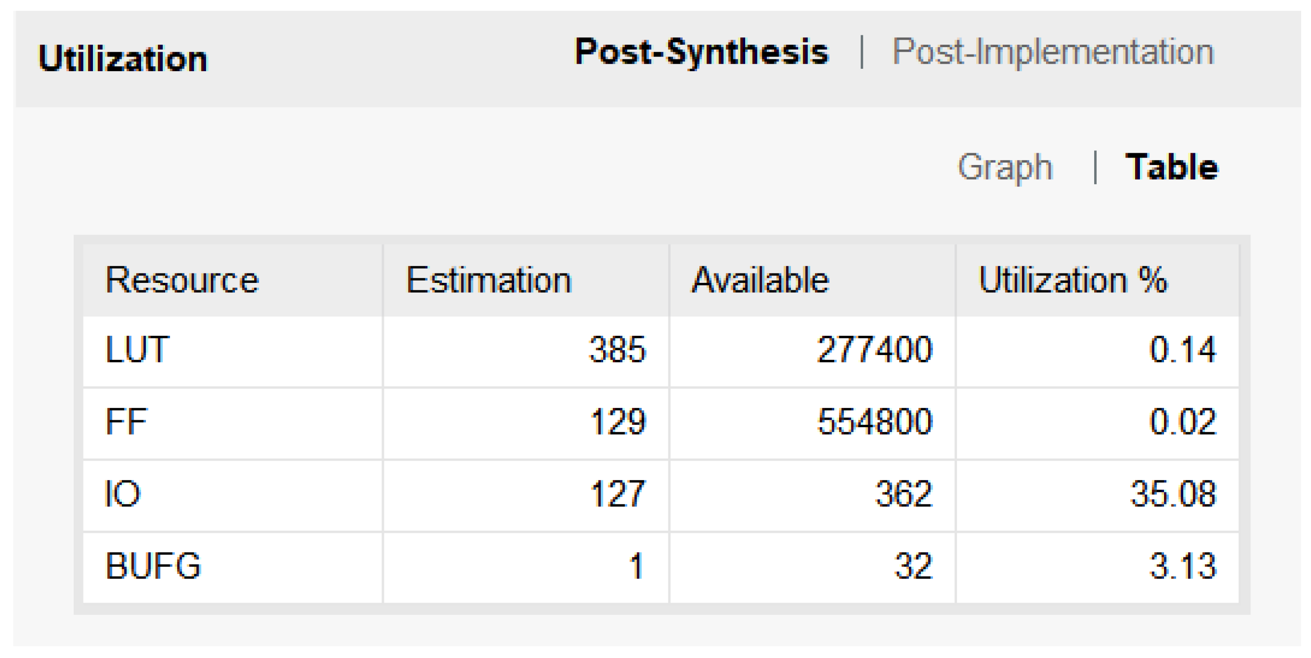
4.2. Resource Consumption
5. Conclusions
Author Contributions
Funding
Data Availability Statement
Conflicts of Interest
References
- Bartunkova, I.; Eissfeller, B. Broadband multi-frequency GNSS signal simulation with GPU. In Proceedings of the 2016 IEEE/ION Position, Location and Navigation Symposium (PLANS), Savannah, GA, USA, 11–14 April 2016; IEEE: Piscataway, NJ, USA, 2016; pp. 477–490. [Google Scholar]
- Mikhaylova, O.K.; Korogodin, I.V.; Lipa, I.V. Universal ranging code generator of GLONASS and GPS open navigation signals. In Proceedings of the 2020 International Youth Conference on Radio Electronics, Electrical and Power Engineering (REEPE), Moscow, Russia, 12–14 March 2020; IEEE: Piscataway, NJ, USA, 2020; pp. 1–5. [Google Scholar]
- Fortin, M.-A.; Landry, R. Implementation Strategies for a Universal Acquisition and Tracking Channel Applied to Real GNSS Signals. Sensors 2016, 16, 624. [Google Scholar] [CrossRef] [PubMed]
- Yang, Y.; Ba, X.; Chen, J. A Novel VLSI Architecture for Multi-Constellation and Multi-Frequency GNSS Acquisition Engine. IEEE Access 2019, 7, 655–665. [Google Scholar] [CrossRef]
- Kim, M.; Park, J.; Jo, G.; Yoo, H. Area-Efficient Universal Code Generator for Multi-GNSS Receivers. Electronics 2021, 10, 2485. [Google Scholar] [CrossRef]
- ISRO. “Satellite Navigation Services.” ISRO—Indian Space Research Organisation. Available online: www.isro.gov.in/ISRO_EN/SatelliteNavigationServices.html (accessed on 23 October 2023).
- Jiang, Y.; Li, J. Design of BDS/GPS C/A Code Generator. In Proceedings of the 2021 4th International Conference on Electron Device and Mechanical Engineering (ICEDME), Guangzhou, China, 13–19 March 2021; IEEE: Piscataway, NJ, USA, 2021; pp. 5–9. [Google Scholar]
- Chityala, H.K.; Nayana, D.K.; Dharmappa, D. PRN sequence design based on Concatenation of Weil Sequences (CWS). In Proceedings of the 2023 2nd International Conference on Vision Towards Emerging Trends in Communication and Networking Technologies (ViTECoN), Vellore, India, 5–6 May 2023; IEEE: Piscataway, NJ, USA, 2023; pp. 1–4. [Google Scholar]
- Park, J.; Jo, G.; Kim, J.; Yoo, H. Area-Efficient On-the-Fly Code Generator for BDS B1C Receivers. In Proceedings of the 2021 International Conference on Electronics, Information, and Communication (ICEIC), Jeju, Republic of Korea, 31 January–3 February 2021; IEEE: Piscataway, NJ, USA, 2021; pp. 1–4. [Google Scholar]
- Park, J.; Kim, M.; Jo, G.; Yoo, H. Area-Efficient Universal Code Generator for GPS L1C and BDS B1C Signals. Electronics 2021, 10, 2737. [Google Scholar] [CrossRef]
- China Satellite Navigation Office. BeiDou Navigation Satellite System Signal in Space Interface Control Document Open Service Signal. Available online: http://www.beidou.gov.cn/rdzt/bdwx/ICD_OpenServiceSignal_BDS-ICD-OS-SIS-V1.0.pdf (accessed on 23 October 2023).
- Global Navigations Satellite System GLONASS. Navigational Radio Signal in Bands L1, L2. Available online: http://docs.cntd.ru/document/465317671 (accessed on 23 October 2023).
- U.S. Air Force. Interface Specification IS-GPS-800H. NAVSTAR GPS Space Segment/User Segment L1C Interfaces. Available online: https://www.gps.gov/technical/icwg/IS-GPS-800L.pdf (accessed on 23 October 2023).
- European Space Agency. Galileo Open Service Signal-In-Space Interface Control Document. Available online: https://www.gsceuropa.eu/sites/default/files/2021-05/GalileoOS-SIS-ICD-V1.3.pdf (accessed on 23 October 2023).
- He, X.; Ba, X.; Liu, X. Analysis of QZSS System L6 Signal. In Proceedings of the 11th China Satellite Navigation Conference—S09 User Terminal Technology, Chengdu, China, 22–25 November 2020; Academic Exchange Center of China Satellite Navigation System Management Office: Shanghai, China, 2020; pp. 36–40. [Google Scholar]
- Kumar, P.V.; Dharmappa, D.; Mishra, S. Interleaved Z4-Linear Sequences with Improved Correlation for Satellite Navigation. In Proceedings of the 2021 IEEE International Symposium on Information Theory (ISIT), Virtual Event, 12–20 July 2021; IEEE: Piscataway, NJ, USA, 2021; pp. 1665–1670. [Google Scholar]
- Puga, G.L. Linear-feedback shift register seed determination for memory-constrained embedded systems. In Proceedings of the 2017 IEEE URUCON, Montevideo, Uruguay, 23–25 October 2017; IEEE: Piscataway, NJ, USA, 2017; pp. 1–4. [Google Scholar]
- Klein, A. Stream Ciphers; Springer: London, UK, 2013. [Google Scholar]
- Kasami, T. Weight Distribution Formula for Some Class of Cyclic Codes; University of Illinois: Champaign, IL, USA, 1966. [Google Scholar]
- Sarwate, D.V.; Pursley, M.B. Crosscorrelation properties of pseudorandom and related sequences. Proc. IEEE 1980, 68, 593–619. [Google Scholar] [CrossRef]


| GNSS | Bandwidth | Signal | Code Structure | Code Type | Length | Code Rate | Note | Markings |
|---|---|---|---|---|---|---|---|---|
| BDS | B1 | B1I | LFSR (11b, 11b) | Gold code | 2046 | 2.046 Mcps | Code generator is the same as B1I The subcode of B2a-p is the Weil code | ➀ |
| L1 | B1C | Legendre sequence | Weil code | 10,230 | 1.023 Mbps | ➁ | ||
| B2 | B2I | LFSR (11b, 11b) | Gold code | 2046 | 2.046 Mcps | ➂ | ||
| L5 | B2a (B2a-d/B2a-p) | LFSR (13b, 13b) | Gold code | 10,230 | 10.23 Mcps | ➃ | ||
| B2b-I | LFSR (13b, 13b) | Gold code | 10,230 | 10.23 Mcps | ➄ | |||
| B3 | B3I | LFSR (13b, 13b) | Gold code | 10,230 | 10.23 Mcps | ➅ | ||
| GPS/QZSS | L1 | L1C/A | LFSR (10b, 10b) | Gold code | 1023 | 1.023 Mcps | ➆ | |
| L1C | Legendre sequence | Weil code | 10,230 | 1.023 Mcps | ➇ | |||
| L2 | L2CM | LFSR (27b) | Equivalent m-sequence [2] | 10,230 | 0.5115 Mcps | ➈ | ||
| L2CL | LFSR (27b) | Equivalent m-sequence [2] | 767,250 | 0.5115 Mcps | ➉ | |||
| L5 | L5I | LFSR (13b, 13b) | Gold code | 10,230 | 10.23 Mcps | ⑪ | ||
| L5Q | LFSR (13b, 13b) | Gold code | 10,230 | 10.23 Mcps | ⑫ | |||
| GLONASS | L1 | L1OF | LFSR (9b) | M-sequence | 511 | 0.511 Mcps | Same as L1OF | ⑬ |
| L1OCd | LFSR (10b, 10b) | Gold code | 1023 | 0.5115 Mcps | ⑭ | |||
| L1OCp | LFSR (12b, 6b) | Kasami code | 4092 | 0.5115 Mcps | ⑮ | |||
| L2 | L2OF | LFSR (9b) | M-sequence | 511 | 0.511 Mcps | ⑯ | ||
| L2OC (L2OCp) | LFSR (14b, 7b) | Kasami code | 10,230 | 0.5115 Mcps | ⑰ | |||
| L3 | L3OC (L3OCd/L3OCp) | LFSR (14b, 7b) | Kasami code | 10,230 | 10.23 Mcps | ⑱ | ||
| Galileo | E1 | E1 | Memory code | Memory code | 4092 | 1.023 Mcps | ⑲ | |
| E5 | E5a (E5a–I/E5a–Q) | LFSR (14b, 14b) | Gold code | 10,230 | 10.23 Mcps | ⑳ | ||
| E5b (E5b–I/E5b–Q) | LFSR (14b, 14b) | Gold code | 10,230 | 10.23 Mcps | ㉑ | |||
| E6 | E6B/C | Memeory code | Memeory code | 2046 | 5.115 Mcps | ㉒ | ||
| IRNSS | L5 | L5-SPS | LFSR (10b, 10b) | Gold code | 1023 | 1.023 Mcps | Code generator is the same as GPS L1C/A | ㉓ |
| S | S-SPS | LFSR (10b, 10b) | Gold code | 1023 | 1.023 Mcp | Code generator is the same as GPS L1C/A | ㉔ | |
| L1 | L1-SPS | LFSR (55b, 55b, 5b) | Interleaved Z4–linear (IZ4) sequences | 10,230 | 1.023 Mcp | Has the longest shift register | ㉕ | |
| QZSS | L1 | L1S | LFSR (10b, 10b) | Gold code | 1023 | 1.023 Mcps | Code generator is the same as GPS L1C/A | ㉖ |
| L5 | L5S | LFSR (13b, 13b) | Gold code | 10,230 | 10.23 Mcps | Code generator is the same as GPS L5I and L5Q | ㉗ | |
| L6 | L6D | LFSR (20b, 10b) | Kasami code | 10,230 | 2.5575 Mcps | ㉘ | ||
| L6E | LFSR (20b, 10b) | Kasami code | 10,230 | 2.5575 Mcps | ㉙ | |||
| SBAS | L1 | L1 | LFSR (10b, 10b) | Gold code | 1023 | 1.023 Mcps | Code generator is the same as GPS L1C/A | ㉚ |
| L5 | L5 | LFSR (13b, 13b) | Gold code | 10230 | 10.23 Mcps | Code generator is the same as GPS L5I and L5Q | ㉛ |
| Codes | Feedback ROM1 (13 bit) | Feedback ROM2 (14 bit) | Output ROM1 (13 bit) | Output ROM2 (14 bit) | Initial ROM1 (13 bit) | Initial ROM2 (14 bit) |
|---|---|---|---|---|---|---|
| L1C/A | 0001000000100 | 00001110100110 | 0001000000000 | 0000xxxxxxxxxx | 0001111111111 | 00001111111111 |
| L2CM | 1001001010010 | 01010100111100 | 1000000000000 | 00000000000000 | xxxxxxxxxxxxx | xxxxxxxxxxxxxx |
| L2CL | 1001001010010 | 01010100111100 | 1000000000000 | 00000000000000 | xxxxxxxxxxxxx | xxxxxxxxxxxxxx |
| L5 I | 1101100000000 | 01100011101101 | 1000000000000 | 01000000000000 | 1111111111111 | 0xxxxxxxxxxxxx |
| L5 Q | 1101100000000 | 01100011101101 | 1000000000000 | 01000000000000 | 1111111111111 | 0xxxxxxxxxxxxx |
| Summary | xx01x0x0x0xx0 | 0xxxxxxx1xx1xx | x00x000000000 | 0x00xxxxxxxxxx | xxxxxxxxxxxxx | xxxxxxxxxxxxxx |
| Mode | Generate Signal Information | |
|---|---|---|
| 0000 | IZ4 Data and Pilot Component Generation (55 bits) | |
| 0001 | B2a Data and Pilot Components (R0 and R1 0–25 bits) | B2b-I branch (bits R0 and R1 26–38) |
| 0010 | E5a-I and Q components (R0 and R1 0–27 bits) | |
| 0011 | Simultaneous generation of two L5 XA sequences (R0 bits 0–25) | Simultaneous generation of two groups of L5 XB_I and Q (R1 bits 0–51) |
| 0100 | Simultaneous generation of five groups of L1C/A (bits R0 and R1 0–49) | |
| 0101 | Simultaneous generation of four groups of B3I (R0 and R1 bits 0–51) | |
| 0110 | Simultaneous generation of four L2C groups (R0 and R1 bits 0–53) | |
| 0111 | IZ4 pilot component secondary code (bits R0 and R1 0–9) | |
| 1000 | Two groups L1C/A (R0 and R1 bits 0–19) | B1I or B2I (R0 and R1 20–30 bits) |
| 1001 | Two groups of L1OCd and L1OCp were generated in parallel (R0 0–43, R1 0–31) | |
| 1010 | Simultaneous generation of three L2OCp or L3OCd, L3OCp (R0 0–41, R1 0–20) | |
| 1011 | E5b-I and Q components (R0 and R1 bits 0–27) | |
| 1100 | Simultaneous generation of L6D/E (R0 0–39, R1 0–19) | |
Disclaimer/Publisher’s Note: The statements, opinions and data contained in all publications are solely those of the individual author(s) and contributor(s) and not of MDPI and/or the editor(s). MDPI and/or the editor(s) disclaim responsibility for any injury to people or property resulting from any ideas, methods, instructions or products referred to in the content. |
© 2024 by the authors. Licensee MDPI, Basel, Switzerland. This article is an open access article distributed under the terms and conditions of the Creative Commons Attribution (CC BY) license (https://creativecommons.org/licenses/by/4.0/).
Share and Cite
Ba, X.; Liu, T.; Jiang, W.; Wang, J.; Cai, B.; Chai, L.; Liang, K. Design of Universal Code Generator for Multi-Constellation Multi-Frequency GNSS Receiver. Electronics 2024, 13, 1244. https://doi.org/10.3390/electronics13071244
Ba X, Liu T, Jiang W, Wang J, Cai B, Chai L, Liang K. Design of Universal Code Generator for Multi-Constellation Multi-Frequency GNSS Receiver. Electronics. 2024; 13(7):1244. https://doi.org/10.3390/electronics13071244
Chicago/Turabian StyleBa, Xiaohui, Taibin Liu, Wei Jiang, Jian Wang, Baigen Cai, Linguo Chai, and Kun Liang. 2024. "Design of Universal Code Generator for Multi-Constellation Multi-Frequency GNSS Receiver" Electronics 13, no. 7: 1244. https://doi.org/10.3390/electronics13071244
APA StyleBa, X., Liu, T., Jiang, W., Wang, J., Cai, B., Chai, L., & Liang, K. (2024). Design of Universal Code Generator for Multi-Constellation Multi-Frequency GNSS Receiver. Electronics, 13(7), 1244. https://doi.org/10.3390/electronics13071244