Abstract
A short reference differential chaotic shift keying communication system based on reference signal scrambling transformation (RSST-SR-DCSK) is proposed in this paper. The system introduces information-bit-driven scramblers at the transmission end to effectively eliminate the correlation between the reference signal and information signal. At the receiving end, a descrambler is used to restore the correlation, thereby enhancing information transmission security. Additionally, the system employs a short reference transmission mechanism to further increase the information transmission rate. The transmitter and receiver structures of the system are designed through signal structure analysis. Theoretical analyses and simulations conducted in an additive white Gaussian noise (AWGN) channel demonstrate promising performance, including a low bit error rate (BER) and a favorable data-energy-to-bit-energy ratio (DBR). Simulation verification is performed to examine the impact of parameters on the bit error rate performance. A comparative analysis with traditional DCSK and SR-DCSK systems highlights the superior performance of the RSST-SR-DCSK system.
1. Introduction
Chaos signals, which are characterized by wide continuous spectra, easy generation, and randomness, can be used as a low-cost carrier for spread-spectrum communication. Systems based on chaos, where information is embedded into chaotic signals, not only inherit the advantages of traditional spread-spectrum communication systems (such as low detection probability, interference resistance, and multipath mitigation) but also enhance data security [1,2]. Chaotic digital modulation techniques are characterized by simple circuits, resistance to interception, and the ability to withstand adverse channel conditions. As a result, they have potential applications in secure communication [3,4]. Therefore, in practical scenarios, non-coherent systems that do not require chaotic synchronization appear to be more feasible and attractive.
Differential chaos shift keying (DCSK) is a non-coherent digital modulation scheme that utilizes chaos. In DCSK, half of the bit duration is dedicated to transmitting a reference chaotic signal, resulting in lower energy efficiency and data rate [5]. DCSK-based communication systems are advantageous for wireless sensor networks due to their low power consumption, low complexity, and resistance to channel distortion. Over the years, significant improvements have been made in the energy efficiency, data rate, and error performance of DCSK. A highly efficient scheme called high-efficiency DCSK (HE-DCSK) was proposed in [6]. This scheme cyclically reuses each reference sample in DCSK, thereby providing twice the data rate of traditional DCSK. The literature introduced multi-carrier DCSK (MC-DCSK) [7], which effectively enhanced the energy efficiency, data rate, and error performance. Furthermore, multi-carrier DCSK was improved in the subsequent literature [8,9]. Another advancement is the short-reference DCSK system (SR-DCSK) proposed in [10,11], which demonstrates improvements in data rate, energy efficiency, and error performance compared to traditional DCSK. Building on SR-DCSK, ref. [12] introduced an index modulation technique applied to the information-bearing signal, allowing for additional information bits. Based on the SR-DCSK principle, the literature [13,14] proposes a short reference code index differential shift keying scheme (SR-DCSK with code indexing) and short reference orthogonal double-speed DCSK to enhance the security performance and transmission rate of communication systems. In [15], a novel carrier phase and code index modulation (DCSK) system was proposed, which demonstrated high transmission rates and low error rates, offering efficiency advantages. To address the low transmission rate drawback of multi-user orthogonal multi-level DCSK (MOM-DCSK) communication systems, ref. [16] introduced a new communication system based on DCSK, achieving higher transmission rates and lower error rates. In order to enhance security and mitigate eavesdropping or malicious attacks in wireless communication systems, ref. [17] designed an FH-OFDM-DCSK-assisted MIMO communication system. Additionally, refs. [18,19] proposed a multi-user OFDM-DCSK system to reduce system integration complexity and improve spectral efficiency. Furthermore, coding technology has been utilized to further enhance DCSK in references [20,21,22]. To enhance the data rate and energy efficiency of DCSK systems, several improvement schemes were proposed in [23,24,25,26].
This article introduces a novel non-coherent communication scheme termed reference signal scrambling transformation short reference differential chaos shift keying (RSST-SR-DCSK). The goal is to enhance the security of SR-DCSK systems. Through signal structure analysis, the design of both transmitter and receiver mechanisms was accomplished, with system performance being assessed via simulations. Results indicate that the proposed approach not only accelerates information transfer rates but also substantially increases the confidentiality of data by incorporating reference signal scrambling into the SR-DCSK system.
The main contributions of this article are as follows:
Initially, a novel non-coherent communication scheme, termed the reference signal scrambling transformation short reference differential chaos shift keying (RSST-SR-DCSK) communication system and method, is proposed to address the security vulnerabilities of SR-DCSK systems. The article delineates the design of the signal frame structure, modulator, and receiver for this system.
Secondly, the paper derived the data-energy-to-bit-energy ratio (DBR) and the theoretical bit error rate of the RSST-SR-DCSK system in Gaussian channels, analyzing its energy efficiency. Compared to DCSK and SR-DCSK systems, the RSST-SR-DCSK system conserves transmitted bit energy and increases data rates.
Finally, through a simulation analysis, the article explores the optimal replication times and semi-spreading factors for the RSST-SR-DCSK system. It is found that under specific signal-to-noise ratios, the RSST-SR-DCSK system outperforms SR-DCSK and DCSK systems in terms of transmission data rates and bit error rates.
2. System Model of RSST-SR-DCSK
The primary limitation of DCSK systems lies in dedicating half of the bit duration to transmitting reference samples for non-carried information, leading to lower data rates and diminished energy efficiency. Consequently, it is crucial to develop new chaos-based communication systems that offer higher data rates and improved energy efficiency. To tackle this challenge, this paper introduces an enhanced RSST-SR-DCSK system designed to boost energy efficiency and transmission rates. This section details several vital elements of the system, encompassing the signal frame structure, and the modulation and demodulation processes of the RSST-SR-DCSK system.
2.1. Chaotic Signal Generator
Chaos signals, due to their noise-like characteristics, are widely studied in the field of communication research as they offer excellent confidentiality when used as carrier signals. One popular method for generating chaotic signals in chaotic digital modulation systems is by utilizing chaotic system mappings. In this paper, we will focus on the statistical characteristics of chaotic signals using the second-order Chebyshev map as an example. The expression for the second-order Chebyshev map is as follows:
Secondly, the probability density function is
Since is an even function, the mean is
Similarly, it is easy to obtain
where represents the mathematical expectation operator, and represents the variance operator.
The second-order Chebyshev map displays different states in different parameter regimes, which correspond to the various ranges of chaotic state parameters in the map. When iterated with initial values of 0.4 and 0.4001, the time–domain plot of the second-order Chebyshev map is depicted in Figure 1. It is evident that even a slight change in the initial chaotic value results in a significant modification of the entire chaotic sequence.
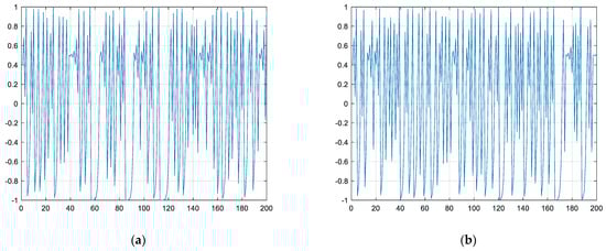
Figure 1.
Time−domain diagram. (a) Second−order Chebyshev map ; (b) second−order Chebyshev map .
2.2. Signal Slot Structure of RSST-SR-DCSK
To enhance the transmission rate of the chaotic communication system, RSST-SR-DCSK utilizes a two-dimensional information transmission scheme. In this scheme, one-dimensional information bits consist of N bits of information. The transmitter’s reference signal is equipped with scramblers at the front end, and N information bits are used to select one of these scramblers for scrambling. At the receiver, descrambling is performed, and the corresponding scrambler is determined by detecting the maximum correlation peak through correlation operations between the descrambled reference signal and the information signal. This process allows the retrieval of N bits of information. The other dimension of information bits consists of M bits of information transmitted by the information signal. Similar to traditional SR-DCSK, in the subsequent time slot, a bit information sequence of length , replicated P times from a reference signal of length R, is transmitted. Figure 2 illustrates the frame structure of the RSST-SR-DCSK system signal, while Figure 3 depicts the frame structure of the DCSK system signal. Through the signal time slot structure, it can be observed that the RSST-SR-DCSK system, by adopting the structure of SR-DCSK, saves time and transmission energy in the reference signal. The information bits utilize a two-dimensional information transmission approach, enhancing the information transmission rate.
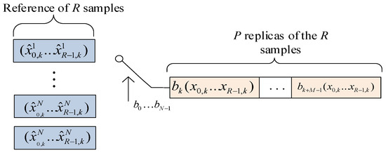
Figure 2.
RSST-SR-DCSK frame.
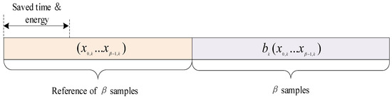
Figure 3.
DCSK frame.
Figure 4 illustrates the time slot structure of RSST-SR-DCSK. In this scheme, the kth frame signal is delayed by , and the reference slot of length R is replicated P times from the delayed ith frame signal. Then, correlation operations are conducted with the signal itself. By making correlation-based decisions, the original two-dimensional information data can be retrieved.
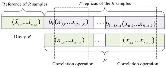
Figure 4.
RSST-SR-DCSK demodulation frame.
2.3. Transmitter Structure of RSST-SR-DCSK
Figure 5 illustrates the transmitter of the RSST-SR-DCSK system. In the front end of the reference slot, the data selector is utilized to transmit N information bits , and the chaotic signal from the chaotic signal generator is formed by selecting one of the scramblers to constitute the reference signal. In the information slot, after replication P times and delaying by , the delayed chaotic signal is multiplied by the pre-set M information bits to obtain the information signal. Taking the kth frame transmission signal as an example, the chaotic signal generated by the chaotic signal generator is scrambled by a scrambler to serve as the reference signal for that symbol period. The reference signal is then replicated P times and delayed by R to obtain . Finally, the two modulated information signals are added together, and the overall result serves as the system’s transmission signal. Here, , , represents the chaotic sequence of length R for the kth frame, and , , represents the reference signal of length R after being scrambled.
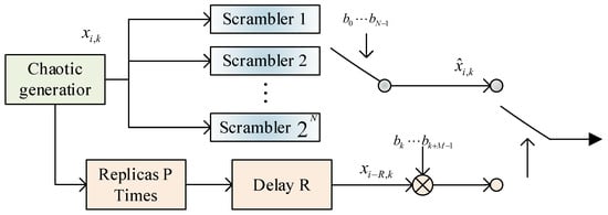
Figure 5.
RSST-SR-DCSK transmitter.
The scrambler unit consists of scramblers, each corresponding to the pre-set N information bits. Each scrambler receives a chaotic signal and generates a scrambled chaotic signal, which is then transmitted to the selection switch. The selection switch chooses the corresponding scrambler based on the pre-set N information bits and obtains the scrambled chaotic signal. This scrambled chaotic signal is used to transmit the N information bits, generating the reference signal. The main purpose of the scrambler is to reduce the correlation between the reference signal and the information signal, thereby improving the security performance of the system. The scrambler configuration can adopt stream cipher construction methods, such as altering the order of the chaotic signal with a finite length, to disrupt the correlation between systems and enhance security. Alternatively, it can use matrix transformations to change signal rows and columns, among other methods.
Assuming that N is set to 2, which corresponds to 4 scramblers, the selection of a particular scrambler is determined based on the two transmitted information bits. For example, if the transmitted information bit is 00, scrambler 1 is selected, and the working principle of scrambler 1 is to swap the signal values corresponding to adjacent positions in a chaotic signal; if the transmitted information bit is 01, scrambler 2 is selected, and the working principle of scrambler 2 is to evenly divide a chaotic signal into two segments, and swap the signal values corresponding to the even positions of the first half of the segment and the odd positions of the second half; if the transmitted information bit is 10, scrambler 3 is selected, and the signal values corresponding to the odd positions of the second half are swapped; if the transmitted information bit is 10, scrambler 3 is selected, and the signal values corresponding to the even positions of the first half are swapped. If the transmitted information bit is 10, scrambler 3 is selected, and the working principle of scrambler 3 is to divide the chaotic signal into four segments equally, and mirror invert the signal values in the first and third segments; if the transmitted information bit is 11, scrambler 4 is selected, and the working principle of scrambler 4 is to divide the chaotic signal into two segments evenly, and mirror invert the signal values corresponding to the even positions in the front and back segments; if the transmitted information bit is 11, scrambler 4 is selected, and the working principle of scrambler 4 is to divide the chaotic signal into two segments evenly, and mirror invert the signal values corresponding to the even positions in the front and back segments. The principle of scrambler 4 is to divide a chaotic signal into two segments equally, and interchange the signal values corresponding to the even positions in the two segments.
The modulation process of the RSST-SR-DCSK system can be summarized in the following steps: Firstly, a chaotic signal of length R is generated and split into two paths. On one path, the chaotic signal is scrambled based on the pre-set N-bit information, resulting in the scrambled chaotic signal. Simultaneously, the other path copies the chaotic signal P times and delays it by R to generate a delayed chaotic signal of length R, where P is equal to the pre-set M-bit information. Next, the delayed chaotic signal is multiplied with the pre-set M-bit information bit by bit, producing an information signal of length . In the third step, the corresponding scrambling method is chosen based on the pre-set N-bit information, and this method is used to scramble one path of the chaotic signal, creating the scrambled chaotic signal. Finally, the reference signal is added to the information signal to form the transmission signal, which is then transmitted through the channel from the sender to the receiver. Therefore, the expression for the RSST-SR-DCSK signal transmitted within the ith frame is
where represents the i-th frame signal; k represents the kth term in the ith frame signal; mod(R) denotes the modulo operation; represents the pre-set M-bit information bits. represents the kth term of the chaotic signal in the 0-th frame, and represents the kth term of the chaotic signal in the ith frame after a delay of L.
represents the kth term of the reference signal in the ith frame, and (1 + P)R represents the length of the transmitted signal, i.e., the sum of the lengths of the reference signal and the information signal.
2.4. Receiver Structure of RSST-SR-DCSK
Figure 6 shows the receiver structure of RSST-SR-DCSK.
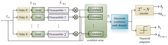
Figure 6.
RSST-SR-DCSK receiver.
During the ith symbol period when the system is recovering information, the demodulator first takes the received signal and delays it by R to obtain . After the descrambling process, it becomes , thus extracting the first R signals in a data frame, which is the reference signal. To correctly demodulate the data information , it is necessary to perform P correlation calculations between the delayed and descrambled reference signal and the actual received information . Finally, the P independently calculated correlation values are summed, and the accumulated signal value is compared with the decision threshold. To demodulate the N-dimensional information , it is necessary to delay the received signal and then pass it through descramblers. Subsequently, we correlate the received signal with the delayed and descrambled reference signal . The descrambler with the maximum absolute value can be identified as the one chosen by the transmitter. Finally, we compare the result with the decision threshold. This process yields the N-dimensional information , and finally, the information data are obtained.
Assuming that N is set to 2, the working principle of the descrambler 1 is to swap the signal values corresponding to adjacent positions in the received signal after L after delay; the working principle of the descrambler 2 is to divide the received signal after L after delay into two segments equally, and swap the signal values corresponding to the even positions in the first half of the segment with the signal values corresponding to the odd positions in the second half; the working principle of the descrambler 3 is to divide the received signal after L after delay into four segments equally, and mirror invert the signal values in the first and third segments. The received signal is divided into four segments equally, and the signal values in the first and third segments are mirrored and inverted; the principle of operation of the disambiguator is that the received signal after the delay L is divided into two segments equally, and the signal values corresponding to the even positions in the front and rear segments are interchanged.
To recover the information bits , the correlator at the receiving end correlates the signal , formed after descrambling , with the delayed received signal . At the end of the ith bit time, the output of the correlator is
which are compared and sent to the threshold detector. The input to the detector at this time instant, denoted by , is given using
where is the noise component, which follows a Gaussian distribution with a mean of 0 and a variance of .
Here, the Gaussian approximation proposed in [27] is utilized to assume that each of the constituent terms of the judgment variable at the receiving end obeys a Gaussian distribution.
Substituting Equation (8) into (7), we find
Notice that the input to the detector consists of three components, namely, the required signal, inter-user interference, and noise.
The kth decoded symbol for the lth user, denoted with , is determined according to the following rule:
The demodulation method can be summarized in the following steps: Firstly, the receiver picks up the signal transmitted through a Gaussian white-noise channel, which is a combination of the transmitted signal and noise. Next, the demodulator receives the signal and outputs the delayed signal after a delay of R, obtaining the signal after descrambling. Subsequently, a correlation operation is performed by multiplying the received signal with its delayed, descrambled counterpart , and the results are accumulated. Following that, threshold decision rules are applied to the output signal to obtain the recovered N-bit and M-bit information bits. Finally, the recovered N-bit information bits are compared with the originally set N-bit information bits, the recovered M-bit information bits are compared with the originally set M-bit information bits, and the bit error rate is calculated. This concludes the demodulation process.
The signal transmission process flowchart of the RSST-SR-DCSK communication system is shown in Figure 7, including structures such as signal generation, the modulator, channel, and demodulator. The following sections provide detailed explanations of each component.
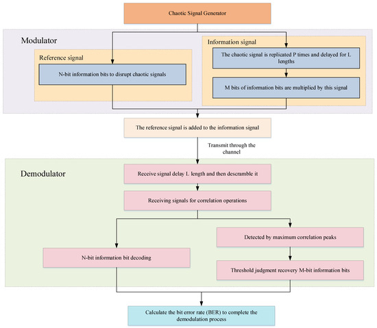
Figure 7.
The framework diagram of the RSST-SR-DCSK communication system.
3. Bit Error Rate Analysis of RSST-SR-DCSK System
Without loss of generality, we consider the probability of error for the first symbol sent by the lth user. The input to the threshold detector at the end of the first symbol duration, now denoted with , is given using
If “+1” is transmitted for the lth user, (4) becomes
If “−1” is transmitted for the lth user, (4) becomes
We assume that all signals (chaotic or noise) are stationary, i.e., the statistical properties of the signals are not dependent on time k. It is important to note that chaotic sequences from different generators are dependent on one another. As a result, the mean value of is equal to Formula (13).
The variance of is found from Formula (14).
The means and variances of given a “+1” or “−1” is sent can be evaluated using numerical simulations. Denote the respective means and variances with and . Since is the sum of a large number of random variables, we may assume that it is normally distributed. Hence, the approximate error probability of the lth transmitted bit is
In order to find the BER, we first obtain the values of the terms (expected values, variances, and covariances) on the right side of the Equations (8) and (9) using numerical simulations. Then, the values of and can be computed and substituted into (15) to obtain the BER. Since both numerical simulation and analytical method are involved in obtaining the BER, we refer to this method as the mixed analysis–simulation (MAS) technique.
First, we assume that the average transmitting power of the chaotic sequence is stable, meaning that the mean square value of the chaotic signal is constant, and writing the mean power , we may simplify (11) and (13) to
and
where , it can be readily shown that all the covariance terms are zero. Thus, using the Formula (17), we may simplify (14) to
Thus, it can be obtained that
We redefine . In other words, the value is a constant, dependent upon only the type of the chaotic sequence but not the average power of the sequence. Now, we rewrite (19) as
Example—consider the case where the Second-order Chebyshev map is used for chaos generation. Formula (20) becomes
4. Analysis of Anti-Jamming Performance
In this section, we will focus on the resistance to interference in spread-spectrum communication systems. Coherent systems, which have knowledge or the ability to replicate the chaotic carrier, are generally better at resisting interference compared to non-coherent systems. However, chaos-based communication faces challenges with chaotic synchronization, which affects the performance of coherent systems. On the other hand, non-coherent systems, while inherently having poorer noise performance than coherent systems, offer practical advantages. Specifically, we present results and evaluations for the scenario where the interference signal is a narrowband sinusoidal interference signal. Our main objective in this chapter is to investigate the performance of chaos-based digital communication systems in the presence of strong interference signals and additive white Gaussian noise. Figure 8 depicts the block diagram of a chaotic communication system with added interference and noise.
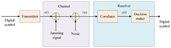
Figure 8.
Block diagram of chaotic communication system with added interference and noise.
According to the impact of narrowband signal interference on communication systems presented in [2], and assuming the interference signal has a power of and is a sinusoidal wave with a carrier frequency of f, i.e.,
where is any constant phase angle, F is the normalized interference frequency defined as , and is the duration of a symbol. Sinusoidal interference signals are one of the most commonly used interference signals and are easy to generate. Assuming the output of the transmitter is s(t), and considering the presence of both additive interference and noise, the signal at the input of the receiver r(t) is given using the following equation.
where is the Gaussian white-noise function. This signal will be used by the receiver to recover the digital signal that the transmitter has sent. Before deriving the bit error rate, let us first consider the bit error rate for the lth bit. Assuming a receiver of the correlator type, the output of the correlator for the lth bit is given using the following equation.
Expanding the above equation and redefining
The following expression represents the decision criteria when the information signal outputs are, respectively, “+1” and “−1”:
where A is the useful information signal, B, C, D is the narrowband interference signal, and G, H, J, K, L is the noise interference signal. Here, the bit error rate for the lth symbol is used to represent the system bit error rate.
Calculate the mean and variance of Equation (21) separately, and we obtain
Substituting Equations (28)–(31) into Equation (27), we find
As can be seen from the above formula, when the interference and noise power spectral density is , the bit error rate can be reduced by reducing the sequence variance and increasing the signal power.
5. Experimental Simulation Analysis
5.1. Energy Efficiency of the RSST-SR-DCSK System
In the RSST-SR-DCSK system, the length of the reference signal within the current symbol period is R, and the length of the information signal is .
In the RSST-SR-DCSK system, taking N as 2 bits as an example, since the reference signal is formed using 4 scramblers and selecting one route from them using a 2-dimensional information bit , the overall signal length of the system is .
The ratio DBR of transmitted data energy to transmitted bit energy in a frame for a 2-bit RSST-SR-DCSK system is given using
The signal energy within a frame for a DCSK system is given by:
Figure 9 illustrates a comparison of the energy utilization rates between RSST-SR-DCSK and DCSK systems. The graph indicates that when P = 2, the performance of SR-ODBR-DCSK and DCSK systems is identical, with both having a DBR of 0.5. However, when P > 2, the RSST-SR-DCSK system demonstrates significantly better energy utilization compared to the DCSK system. As P increases, the DBR of the RSST-SR-DCSK system approaches 0.95. Consequently, the RSST-SR-DCSK system exhibits higher energy efficiency in comparison to the traditional DCSK system.
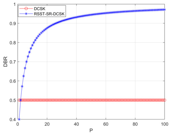
Figure 9.
Comparison of DBR between RSST-SR-DCSK system and DCSK system.
5.2. Confidentiality Analysis
The RSST-SR-DCSK communication method utilizes scrambling to alter the reference signal, making it difficult for non-cooperative parties to demodulate the original chaotic signal without the inverse transformation used in the scrambling process. The scrambler essentially encrypts the chaotic reference signal, thereby increasing the complexity of signal decryption for non-cooperative parties and improving the confidentiality of the physical layer communication signal. In Figure 10, simulation results depict the cross-correlation between the reference signal and the information signal for both the RSST-SR-DCSK and SR-DCSK systems. These results demonstrate that the correlation peaks of RSST-SR-DCSK are notably weakened after scrambling, thereby reducing the correlation between the reference signal and the information signal within the system.
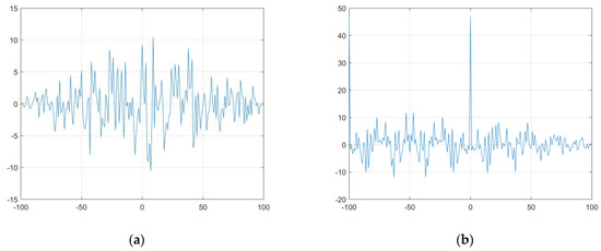
Figure 10.
Comparison correlation between RSST-SR-DCSK and SR-DCSK. (a) RSST-SR-DCSK Correlation Chart; (b) SR-DCSK Correlation Chart.
RSST-SR-DCSK is a system that scrambles the reference signal, resulting in a modified waveform compared to the original chaotic signal. This modification reduces the correlation between the reference signal and the information signal, thereby enhancing the confidentiality of the communication signal to a certain degree. Simulations have shown that the RSST-SR-DCSK system demonstrates improved resistance to interception and enhanced confidentiality.
5.3. The Impact of Different Replication Times P on the System
The length of the information slot in the RSST-SR-DCSK system is denoted as , where P is the number of times the reference signal is copied, and R is the length of the reference signal. When changing P, the length of the information slot in the system also varies, with the reference slot being relatively short. Simulation tests are conducted to assess the impact of the replication count P on the system.
Figure 11 illustrates the selection of simulation parameters for the RSST-SR-DCSK system. Second-order Chebyshev mapping is used with an initial value of 0.4. The effect of varying values of P on the system’s bit error rate is examined for two conditions: R = 64 and R = 256. Based on graphs (a) and (b), it can be observed that when P is 2, the system’s BER is approximately 1 dB higher compared to the case when P is 4.
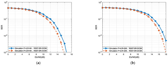
Figure 11.
Effect of different P on RSST-SR-DCSK system error performance. (a) R = 64; (b) R = 256.
5.4. Effect of Spread Spectrum Factor on System Performance
Simulation parameters include second-order Chebyshev mapping with an initial value of 0.4, and spreading factors are chosen as 32, 64, 128, and 256. The impact of spreading factors on the RSST-SR-DCSK system is illustrated in Figure 12. In graph (a), second-order Chebyshev mapping with an initial value of 0.4 and P = 2 is employed, while graph (b) uses the same mapping with P = 4. From graph (a), it can be observed that the system’s bit error rate performance is optimal when P = 2 and R = 32. At this point, the system performs approximately 1 dB better than the system with R = 64 and about 2 dB better than the system with R = 128. This indicates that as the spreading factor increases, the system’s error performance relatively weakens.
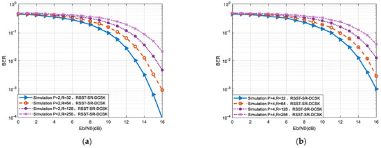
Figure 12.
BER simulation of RSST-SR-DCSK system with different semi spread spectrum factors. (a) P = 2; (b) P = 4.
Figure 13 compares the error performance of three different systems, an RSST-SR-DCSK system, DCSK system mentioned in [5], SR-DCSK system mentioned in [10], and under a Gaussian white-noise channel. The BER of these systems are compared and analyzed for the same spreading factor.
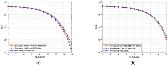
Figure 13.
Comparison of the BER of four different systems. (a) R = 100; (b) R = 150.
Based on the observations from Figure 13a, it can be noted that setting the spreading factor R to 100 results in similar bit error rate performance between the RSST-SR-DCSK system and the SR-DCSK system. However, the DCSK system demonstrates better error performance, exhibiting approximately 1 dB higher performance compared to the other two systems at the same BER value. In Figure 13b, with a spreading factor R of 150, the DCSK system continues to exhibit better error performance, again showing approximately 1 dB higher performance compared to the other two systems at the same BER value. Overall, increasing the value of R leads to varying degrees of increase in the bit error rates of all systems. Consequently, further investigation is required to assess the impact of different R values on the systems and determine the most suitable R value for the system.
Figure 14 is a comparative graph depicting the relationship between the number of sub-spreading factors and the BER for the RSST-SR-DCSK, the MC-ODBR-DCSK system mentioned in [8], and the SR-ODBR-DCSK system mentioned in [14]. The graphs consider a Gaussian white-noise channel with a signal-to-noise ratio of 13 db. As the number of sub-spreading factors increases, both systems show an initial improvement in error performance followed by a decrease. The error performance trends are similar for all three systems, with performance troughs occurring at minimum values of around 14, 12, and 20, respectively. It is clear that when the expansion factor is below these troughs, the error performance of the systems is better, while when these values are exceeded, the error performance gradually deteriorates.
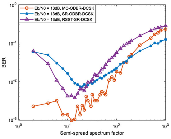
Figure 14.
Comparison of optimal spreading factors for different systems.
6. Conclusions
In response to the security shortcomings of the DCSK system, we have introduced an innovative communication method called reference signal scrambling transformation short reference differential chaos shift keying (RSST-SR-DCSK). This approach integrates short reference differential chaos shift keying technology with reference signal scrambling transformation to enhance transmission speed, strengthen system security, and improve the error rate performance of the communication system.
In RSST-SR-DCSK, we utilize the characteristics of chaotic sequences to eliminate the correlation between the reference signal and the information signal through the reference signal scrambling transformation. This transformation makes it more difficult for the reference signal to be intercepted or deciphered during transmission, thereby enhancing the overall security of the communication system. Additionally, RSST-SR-DCSK has achieved significant improvements in transmission speed and error rate performance. By carefully designing the scrambling transformation of the reference signal, we have successfully optimized the system’s error rate, improving the reliability and stability of the communication system.
Currently, we have studied the software simulation of RSST-SR-DCSK scheme, and in the future, we hope to implement the work of chaotic communication signal generation and the modulation scheme using USRP hardware platform. The RSST-SR-DCSK system combines short reference differential chaos shift keying technology with the scrambling transformation of the reference signal to comprehensively enhance the security, transmission speed, and error rate performance of the DCSK system.
Author Contributions
Conceptualization, Y.F.; data curation, Q.Y.; investigation, F.L.; methodology, T.S.; writing—original draft, B.Q. All authors have read and agreed to the published version of the manuscript.
Funding
This work is supported in part by the National Natural Science Foundation of China (Grant No. 61971291), the science and technology funds from Liaoning Education Department (serial number: JYTMS20230199), and the science and technology funds from Liaoning Education Department (serial number: LJKZ0242).
Data Availability Statement
Data is contained within the article.
Conflicts of Interest
The authors declare no conflicts of interest.
References
- Kolumbán, G.; Kennedy, M.P.; Chua, L.-O. The role of synchronization in digital communications using chaos—Part I: Fundamentals of digital communications. IEEE Trans. Circuits Syst. I Fundam. Theory Appl 1997, 44, 927–936. [Google Scholar] [CrossRef]
- Lau, F.C.M.; Tse, C.-K. Chaos-Based Digital Communication Systems; Springer: Berlin/Heidelberg, Germany, 2003. [Google Scholar]
- Hu, W.; Wang, L.; Kaddoum, G. Design and performance analysis of a differentially spatial modulated chaos shift keying modulation system. IEEE Trans. Circuits Syst. II Express Briefs 2017, 64, 1302–1306. [Google Scholar] [CrossRef]
- Liu, F.; Feng, Y.-X. Dynamic Multimapping Composite Chaotic Sequence Generator Algorithm. Int. J. Electron. Commun. 2019, 107, 231–238. [Google Scholar] [CrossRef]
- Kolumbán, G.; Vizvári, B.; Schwarz, W.; Abel, A. Differential chaos shift keying: A robust coding for chaotic communication. In Proceedings of the 4th International Workshop on Nonlinear Dynamics of Electronic Systems, Sevilla, Spain, 27–28 June 1996; Volume 6, pp. 87–92. [Google Scholar]
- Yang, H.; Jiang, G.-P. High-efficiency differential-chaos-shift-keying scheme for chaos-based noncoherent communication. IEEE Trans. Circuits Syst. II Express Briefs 2012, 59, 312–316. [Google Scholar] [CrossRef]
- Kaddoum, G.; Richardson, F.-D.; Gagnon, F. Design and analysis of a Multi-Carrier differential chaos shift keying communication system. IEEE Trans. Commun. 2013, 61, 3281–3291. [Google Scholar] [CrossRef]
- Sui, T.; Feng, Y.; Qian, B.; Liu, F.; Jiang, Q.; Li, X. Design and Analysis of a Multi−Carrier Orthogonal Double Bit Rate Differential Chaotic Shift Keying Communication System. Electronics 2023, 12, 1785. [Google Scholar] [CrossRef]
- Chen, Z.-W.; Zhang, L.; Wu, Z.-Q.; Wang, L.; Xu, W. Reliable and efficient sparse code spreading aided MC-DCSK transceiver design for multiuser transmissions. IEEE Trans. Commun. 2021, 69, 1480–1495. [Google Scholar] [CrossRef]
- Kaddoum, G.; Soujeri, E.; Nijsure, Y. Design of a Short Reference Noncoherent Chaos-Based Communication Systems. IEEE Trans. Commun. 2016, 64, 680–689. [Google Scholar] [CrossRef]
- Kaddoum, G.; Tran, H.-V.; Kong, L.; Atallah, M. Design of Simultaneous Wireless Information and Power Transfer Scheme for Short Reference DCSK Communication Systems. IEEE Trans. Commun. 2017, 65, 431–443. [Google Scholar] [CrossRef]
- Xu, W.; Wang, L. CIM-DCSK: A differential chaos shift keying scheme with code-index modulation. In Proceedings of the 2016 16th International Symposium on Communications and Information Technologies (ISCIT), Qingdao, China, 26–28 September 2016; Volume 16, pp. 100–104. [Google Scholar]
- Guo, R.; Li, M.; Liu, X.; Wei, Z. Research on Space Laser Hybrid Chaotic Shift Keying Secure Communication System. In Proceedings of the 2020 International Conference on Wireless Communications and Smart Grid (ICWCSG), Qingdao, China, 12–14 June 2020; pp. 14–17. [Google Scholar]
- Sui, T.; Feng, Y.-X.; Jiang, Q.; Liu, F.; Zhang, T. Design and Analysis of a Short Reference Orthogonal Double Bit Rate Differential Chaotic Shift Keying Communication Scheme. Electronics 2022, 11, 2020. [Google Scholar] [CrossRef]
- Zhang, G.; Lai, R.-C.; Jiang, Z.-J. A Noise Reducing Multi-carrier DCSK Communication System Based on Carrier Phase and Code Index Modulation. Wirel. Pers. Commun. 2023, 130, 1295–1316. [Google Scholar] [CrossRef]
- Zhang, G.; He, P.; He, L. Multi-carrier multi-level DCSK communication system based on time-reversal. Ann. Telecommun. 2023, 78, 235–247. [Google Scholar] [CrossRef]
- Qiu, W.; Yang, Y.; Feng, Y.; Zhang, L.; Wu, Z. Secure MIMO Communication System with Frequency Hopping Aided OFDM-DCSK Modulation. Electronics 2022, 11, 3029. [Google Scholar] [CrossRef]
- Kaddoum, G. Design and performance analysis of a multi-user OFDM based differential chaos shift keying communication system. IEEE Trans. Commun. 2016, 64, 249–260. [Google Scholar] [CrossRef]
- Liu, Z.-F.; Cheung, S.-H.; Zhang, L.-L.; Xiao, P. Robust Receiver for OFDM-DCSK Modulation via Rank-1 Modeling and ℓp-Minimization. Signal Process. 2021, 188, 108219. [Google Scholar] [CrossRef]
- Zhu, Z.-Q.; Chen, P.-P.; Lin, Z.-J.; Chen, H.-Y.; Fang, Y. DPI DCSK Modulation with BCJR Decoding. Int. J. Bifurc. Chaos 2023, 33, 2350042. [Google Scholar] [CrossRef]
- Cai, X.-M.; Xu, W.-K.; Hong, S.-H.; Wang, L. A Trinal-Code Shifted Differential Chaos Shift Keying System. IEEE Commun. Lett. 2021, 25, 1000–1004. [Google Scholar] [CrossRef]
- Ma, H.; Cai, G.-F.; Fang, I.; Chen, P.-P.; Chen, G.-R. Design of a Superposition Coding PPM-DCSK System for Downlink Multi-User Transmission. IEEE Trans. Veh. Technol. 2020, 69, 1666–1678. [Google Scholar] [CrossRef]
- Chen, M.-L.; Xu, W.-K.; Wang, D.-Q.; Wang, L. Multi-carrier chaotic communication scheme for underwater acoustic communications. IET Commun. 2019, 13, 2097–2105. [Google Scholar] [CrossRef]
- Sahin, M.-E.; Kolumbán, G.; Hamamci, S.-E.; Guler, H. Use of memristor-based chaotic circuits in AM-DCSK and FM-DCSK modulation. Phys. Scr. 2023, 98, 105228. [Google Scholar] [CrossRef]
- Cai, X.-M.; Xu, W.-K.; Hong, S.-H.; Wang, L. Discrete W Transform Based Index-Keying M-Ary DCSK for Non-Coherent Chaotic Communications. IEEE Commun. Lett. 2021, 25, 3104–3108. [Google Scholar] [CrossRef]
- Biswas, N.; Mohamed, I.-R. DCSK performance analysis of a chaos-based communication using a newly designed chaotic system. Int. J. Nonlinear Sci. Numer. Simul. 2021, 23, 579–592. [Google Scholar] [CrossRef]
- Sushchik, M.; Tsimring, L.-S.; Volkovskii, A.-R. Performance analysis of correlation-based communication schemes utilizing chaos. IEEE Trans. Circuits Syst. I Fundam. Theory Appl. 2000, 47, 1684–1691. [Google Scholar] [CrossRef]
Disclaimer/Publisher’s Note: The statements, opinions and data contained in all publications are solely those of the individual author(s) and contributor(s) and not of MDPI and/or the editor(s). MDPI and/or the editor(s) disclaim responsibility for any injury to people or property resulting from any ideas, methods, instructions or products referred to in the content. |
© 2024 by the authors. Licensee MDPI, Basel, Switzerland. This article is an open access article distributed under the terms and conditions of the Creative Commons Attribution (CC BY) license (https://creativecommons.org/licenses/by/4.0/).