Abstract
This paper presents an innovative solution that is able to suppress the thrust ripple in a high-power asynchronous linear induction motor (LIM) used in a microgravity experiment facility electromagnetic launch (MEFEL) system. By addressing the crucial need for low levels of thrust ripple in MEFEL applications, we propose a dynamic model-based adaptive controller (MAC) and an enhanced quasi-proportional-resonant (PR) controller. The MAC is designed to compensate for the inherent impedance asymmetry of the linear motor. The PR controller minimizes thrust ripple by eliminating harmonics within the current loop. A comparative analysis indicates that both MAC and PR control are effective in reducing harmonics, suppressing the thrust ripple, and maintaining system stability. Computer simulations show a noteworthy 75% reduction in the thrust ripple and a decrease in the negative current. Partial tests on the MEFEL device validate the practical efficacy of the proposed control methods, emphasizing the method’s ability to enhance the quality of microgravity in real-world scenarios significantly.
1. Introduction
The electromagnetic microgravity experimental facility is a device used to simulate space environments on Earth [1]. Microgravity drop towers usually simply drop the experimental capsule from the top of the tower to create a microgravity environment. The improved drop towers are equipped with catapult systems to launch the experimental capsule so that the experimental capsule can perform the round-way free-fall motion. The ability to achieve microgravity time could be doubled by using catapult methods. There are two main ways to catapult the experimental capsule in drop towers, hydraulic catapult and linear motor catapult. Compared with hydraulic catapult, the method using linear motors has a better overload character which benefits the microgravity experimental objects.
This paper researches an electromagnetic microgravity facility system as shown in Figure 1, which utilizes linear induction motors to drive the experimental capsule [2]. The microgravity environment within the experimental capsule is generated by vertically catapulting the experimental capsule using a LIM. During the free-fall motion of the experimental capsule, microgravity experiments can be conducted within the capsule [3]. To achieve the precision necessary for microgravity experiments [4], the LIM’s natural thrust ripple must be controlled through advanced methods.
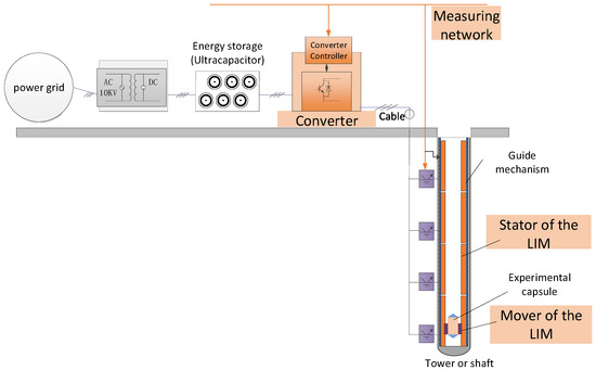
Figure 1.
Microgravity electromagnetic catapult experimental system.
Apart from their application in microgravity facilities, LIMs are widely used in high-power and high-speed applications [5,6], ranging from aircraft carrier electromagnetic catapults to the field of rail transportation. Thrust ripple suppression is a common challenge faced in the study of LIMs. The structure of the LIM is shown in Figure 2, where the finiteness of both stator and mover generates end effects, thereby causing the thrust ripple. In order to investigate the exact mechanisms of the thrust ripple, scholars have meticulously analyzed the model of the LIM through various approaches. Scholarly research on thrust ripples in LIMs is primarily focused on three aspects. The first involves analyzing the magnetic field changes in the structure of linear motors from a magnetic field perspective to understand the characteristics of flux variations and the resulting thrust ripples [7,8]. However, this approach often relies on simulation for theoretical analysis and is challenging to integrate with practical control applications. The second aspect involves analyzing the impedance asymmetry of LIMs from a mathematical model perspective [9,10]. One study [9] mainly analyzes impedance asymmetry in the ABC coordinate system, while another [10] provides a coordinate system’s inductance matrix model, which is more convenient for application in field-oriented control (FOC) systems. The third aspect involves analyzing the equivalent circuit perspective, introducing a coefficient at the excitation inductance to reflect the end effects of a LIM [11,12,13].
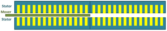
Figure 2.
Linear induction motor.
This study focuses on analyzing the thrust ripples of LIMs based on a mathematical model, where the parameters can be obtained through experimental measurements. Research indicates that the impedance asymmetry in LIMs manifests as an imbalance in currents in the control system [9,14,15]. Therefore, reducing thrust ripples can be achieved by eliminating current imbalances. Study [16] indicates that when the stator currents in a LIM exhibit three-phase balance, the three-phase voltages must be unbalanced. Thus, improvements to traditional three-phase voltage sources are necessary to eliminate thrust ripples. One proposed enhancement involves injecting negative sequence voltage harmonics [17,18,19]. However, this method faces difficulties in practical engineering applications due to complex calculations and the need to parallel two power sources, which is detrimental to the stability of the control system. Some scholars have addressed the issue of current imbalance by eliminating harmonics in the -axis currents in FOC, such as applying dynamic adjustments of the reference values for dq-axis currents to eliminate thrust ripples [20], or adding PR controllers to dq-axis currents [21,22]. However, -axis currents are obtained through Clark–Park transformation, and the parameters in Clark–Park are based on a three-phase symmetrical sinusoidal system. For LIMs, at least one of the currents or voltages is imbalanced, making direct improvements to -axis currents in FOC less precise.
In summary, previous research has either focused on the establishment of models or on model-free control methods. This research investigates whether the control effect can be further improved by utilizing model-based adaptive control based on known motor parameters. This is achieved by introducing a model-based controller for adjusting the voltage phase, thereby reducing current imbalance and suppressing the thrust ripple. In the current controller, the harmonics of id and iq are analyzed and a quasi-PR controller is employed to reduce the harmonics which also contributes to the suppression of the thrust ripple. The results and discussions of the simulation demonstrate that both the model-based controller and the quasi-PR controller can reduce the current imbalance and suppress the thrust ripple.
2. LIM Models and Design of MAC
This section discusses the differences between LIM models and rotary motor models. By addressing the uniqueness of the LIM, a model-based adaptive controller is proposed for eliminating the imbalance of current phase.
The representation of the linear induction motor in the equivalent circuit can manifest in various forms [11,12,13], involving the introduction of end effect coefficients at the rotor leakage inductance and excitation inductance to capture the asymmetry inherent in the LIM model. This study researched the relationship between excitation inductance in the equivalent model and the mutual inductance in the flux model, providing the feasibility of fixing the current imbalance through adjusting the voltage phase.
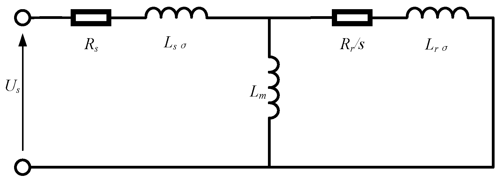
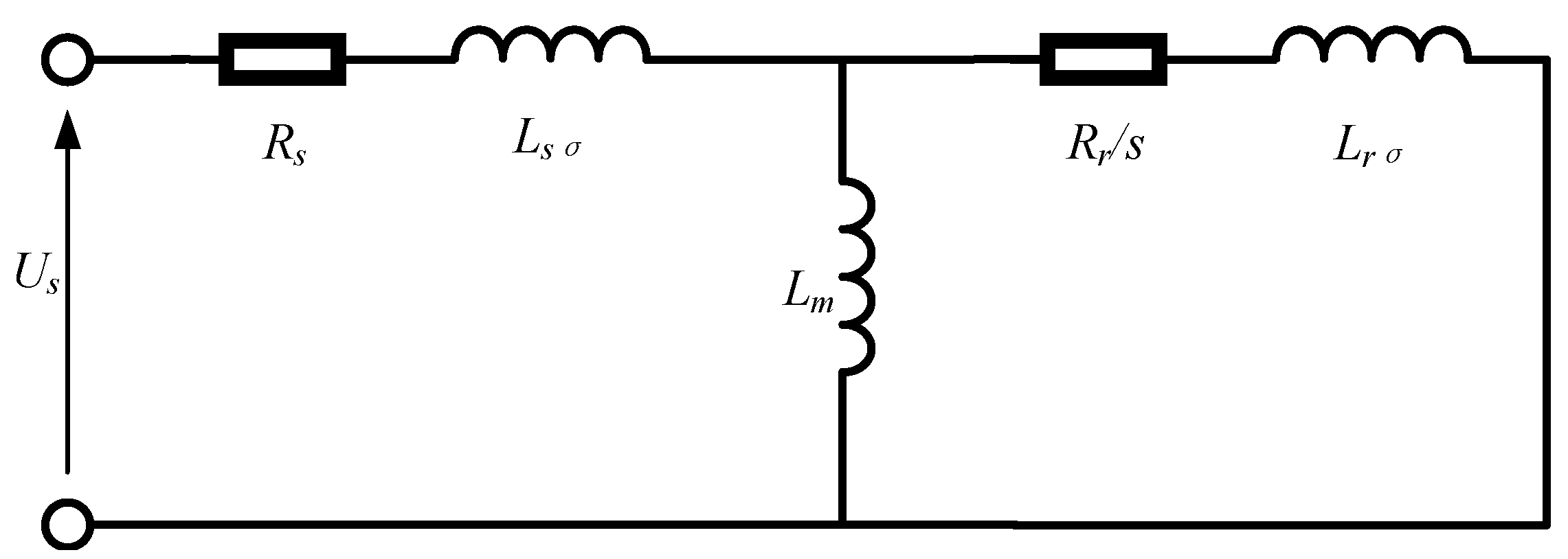
The steady-state model of a rotary induction motor is commonly expressed as the following equivalent circuit shown in Figure 3, where and are the stator resistance and stator leakage inductance. and are the rotor resistance with slip rate and rotor leakage inductance referred to the stator side. is the excitation inductance. is the voltage of stator winding.

Figure 3.
T-type equivalent circuit.
The excitation inductance in the equivalent circuit satisfies the following:
where is the excitation inductance and is the main self-inductance of stator windings. The circuit itself reflects the voltage–current relationship of a single-phase winding. In rotary induction motors, the three-phase parameters are equal so the equivalent circuit can represent three-phase windings.
However, in LIMs the excitation inductances of three-phase windings are not equal due to the imbalance of stator inductance matrix. When the currents are balanced, the excitation inductances can be expressed as (The detailed derivation process can be found in Appendix A)
where , and are the excitation inductances of phase A, phase B, and phase C. , and are the self-inductances of phase A, phase B, and phase C. is the mutual inductance of phase A and phase B. is the mutual inductance of phase A and phase C. is the mutual inductance of phase A and phase C. is the stator inductance matrix. In a rotary motor, the stator flux caused by stator current can be expressed as follows:
where represents the stator–stator flux in phase A. , , and are the phase currents of the stator. In LIM, the stator–stator flux in phase A can be expressed as follows:
The calculation process for phases B and C is the same as that for phase A.
The asymmetry of results in the imbalance of three-phase currents because the voltage references from the control system are standard sinusoidal three-phase waves. Hence, the motivation of this research is to find a controller which can fix the current imbalance problem by adjusting the voltages.
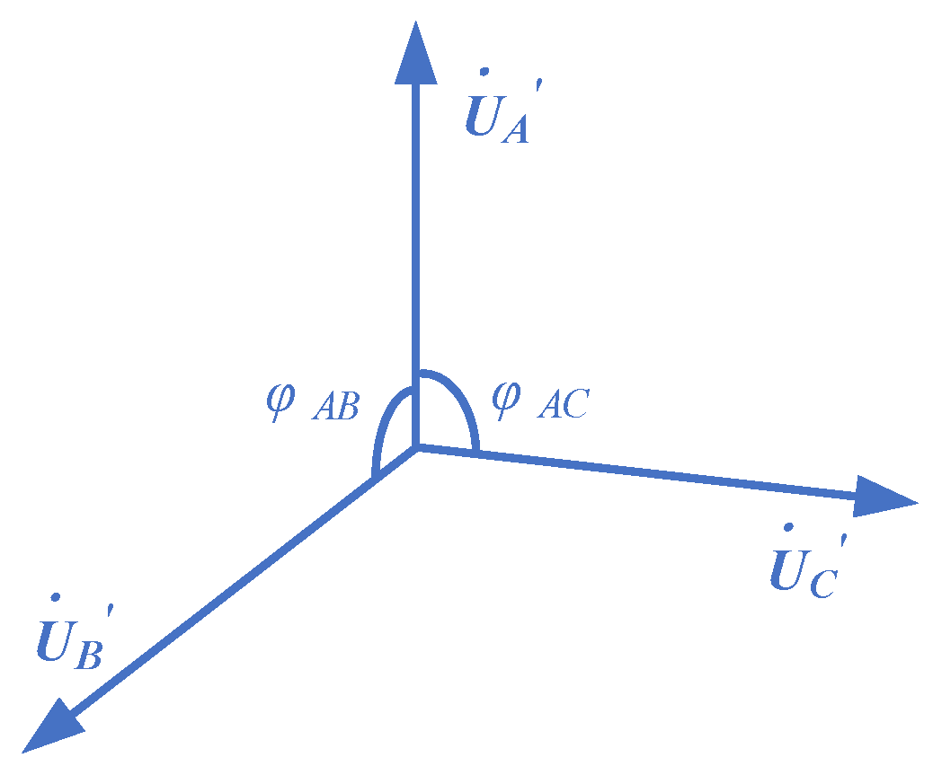
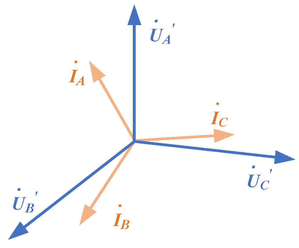
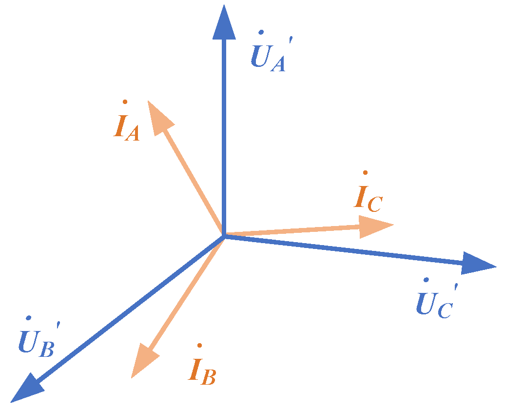
Sine waves of voltage and current can both be represented using vectors as shown in Figure 4. The impedance is a complex value that can also be represented using vector notation. Based on the Equation (2), the impedances of each phase winding are expressed as , , and . The phase difference of voltage can be calculated through the impedance of the three-phase windings when current is balanced.
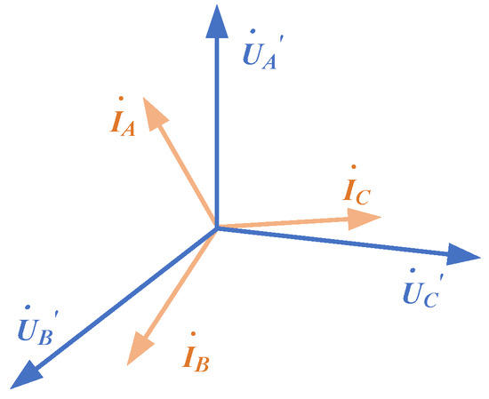
Figure 4.
Vector diagram of voltages and currents.
Define and which satisfy the following:
Hence, the model-based adaptive controller can be designed to adjust the phase differences of the voltages by tuning the angles in the Clark transformation, thereby suppressing current imbalance.
where , , and represent standard sinusoidal voltage reference values before adjustment and , , and represent the post-adjustment voltage reference values (We can prove that the current phase is balanced after the adjustment in Appendix B).
Based on the provided equations, the controller can optimize the voltage signals of the three phases, thereby reducing the current imbalance and suppressing the thrust ripple. In the commonly used field-oriented control (FOC) system for LIMs, the Equation (9) can be employed as a replacement of the transformation module.
where and are the voltages of d axis and q axis in FOC, and is the electrical angle. Here, we define this control strategy as a MAC, since the control matrix is adaptive to the model and changes over time.
3. Thrust Ripple Analysis and Design of Quasi-PR Controller
The introduction of the MAC eliminated the “phase imbalance” in current phase by adjusting the voltage. However, the issue of current “amplitude imbalance” has not been addressed. In the field-oriented control (FOC) system, the controlled variables and are both in direct current. The imbalance in current amplitude manifests as fluctuations in the -axis and -axis currents. Therefore, this paper considers adopting an appropriate dynamic control method to mitigate the fluctuations in the d-axis and q-axis currents.
The unbalanced three-phase sinusoidal waves can be decomposed into positive-sequence, negative-sequence, and zero-sequence components using the orthogonal component method. In LIMs, the negative-sequence component of the current introduces thrust ripple and fluctuations in the -axis and -axis currents. There are two types of thrust ripple that exist in LIMs [10]. One is the thrust ripple at a frequency of 2f (where f represents the supply frequency) generated by the stator negative-sequence current, and the other is the thrust fluctuation at a frequency of 2sf (where s represents slip) generated by the rotor negative-sequence current. In FOC, the thrust ripple at a frequency of 2f can be suppressed by reducing the stator negative-sequence current.
In the control system under FOC, the thrust ripple caused by negative sequences of stator currents results in harmonics of and in current loop. The proportional-resonant (PR) controller exhibits excellent control performance in eliminating harmonics at specific frequencies. The transfer function of the ideal PR controller is given by
Due to the high precision requirements of the ideal PR controller for the controlled object’s parameters, its practical application may lead to less desirable control results. Therefore, a quasi-PR controller is utilized to address this issue [20,21].
Typically, a quasi-PR controller is used to eliminate specific harmonics with fixed value of ωc. In the context of this study, the harmonic frequency ωc is where is the frequency of stator currents. Thus, the transfer function for the quasi-PR controller used in the LIM can be expressed as follows:
The PI controller can be expressed as:
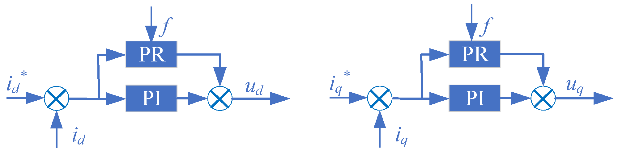
Both the quasi-PR controller and the PI controller include a proportional component. In this study, the value of Kp for the quasi-PR controller is set to 0. In the subsequent simulations and experiments, the PR controller employed is the modified quasi-PR controller, as illustrated in Equation (12). The current loop is represented as shown in Figure 5, in which the asterisk (*) denotes the reference value.
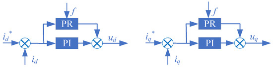
Figure 5.
Current controllers for the adaptation of the quasi-PR controller.
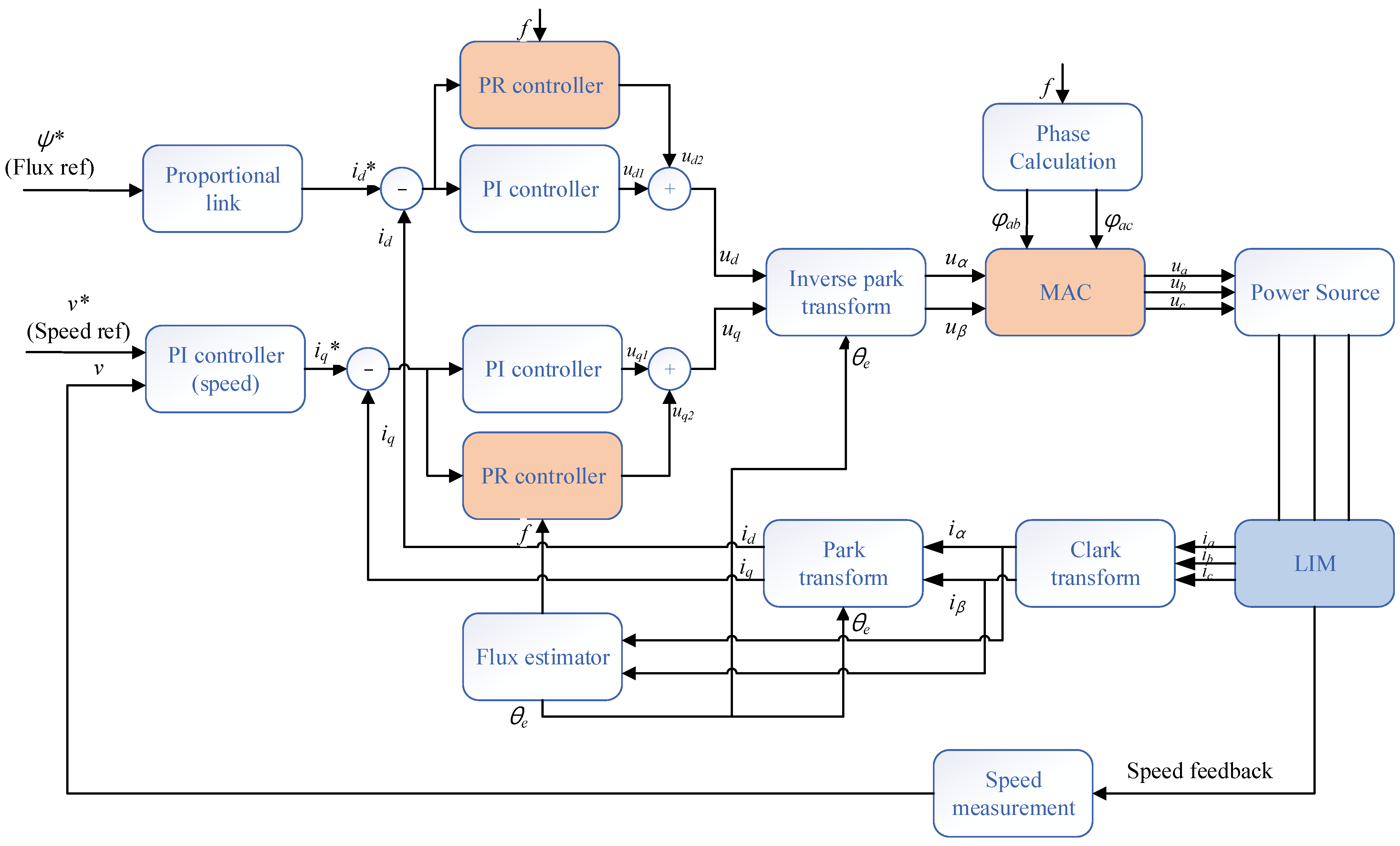
The control system diagram of the research is illustrated as shown in Figure 6, in which the asterisk (*) denotes the reference value. Two control methods are employed to suppress the thrust ripple caused by stator current imbalance. The first method involves introducing the MAC to correct the phase imbalance of the stator current, and the second method incorporates the PR controller to correct the amplitude imbalance of the stator current.
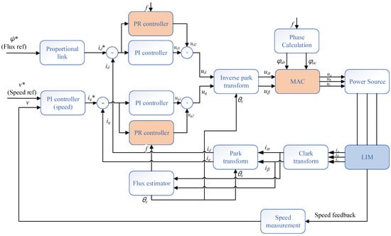
Figure 6.
Framework of the control system.
4. Simulation Results and Discussions
4.1. Simulation Parameters
In this section, simulation results validate the optimization results of the MAC and the PR controller in the FOC system. The simulation system is built using Simulink (Matlab R2022b), and the LIM is implemented through an S-function based on the magnetic flux linkage equation. The designed parameters of the LIM investigated in this study are presented as shown in Table 1.

Table 1.
Designed parameters of the LIM for simulation.
In the simulated linear motor model, the inductance matrix is configured with the LAA set at 1.28 × 10⁻³ mH, whereas both LBB and LCC are established at 0.97 × 10⁻³ mH. This deliberate parameterization serves to emulate the impedance asymmetry characteristics of practical motor systems. This paper models the motor control system using Simulink (Matlab R2022b), where the motor model is designed as a flux linkage model based on the motor impedance parameters and implemented as an S-function block. The studied control system is a FOC system. In the current loop section, the PI controller and quasi-PR controller are connected in parallel. The parameters for the d-axis current PI controller are Kp = 0.5, Ki = 100, and those for the quasi-PR controller are Kr = 1000, with a bandwidth of b = 10 Hz. The parameters for the q-axis current PI controller are Kp = 0.7, Ki = 80, and those for the quasi-PR controller are Kr = 1000, with a bandwidth of b = 10 Hz. The control parameters are shown in Table 2.
Table 2.
Control parameters.
4.2. Simulation Curves and Data
4.2.1. Mechanical Characteristics Simulation Results
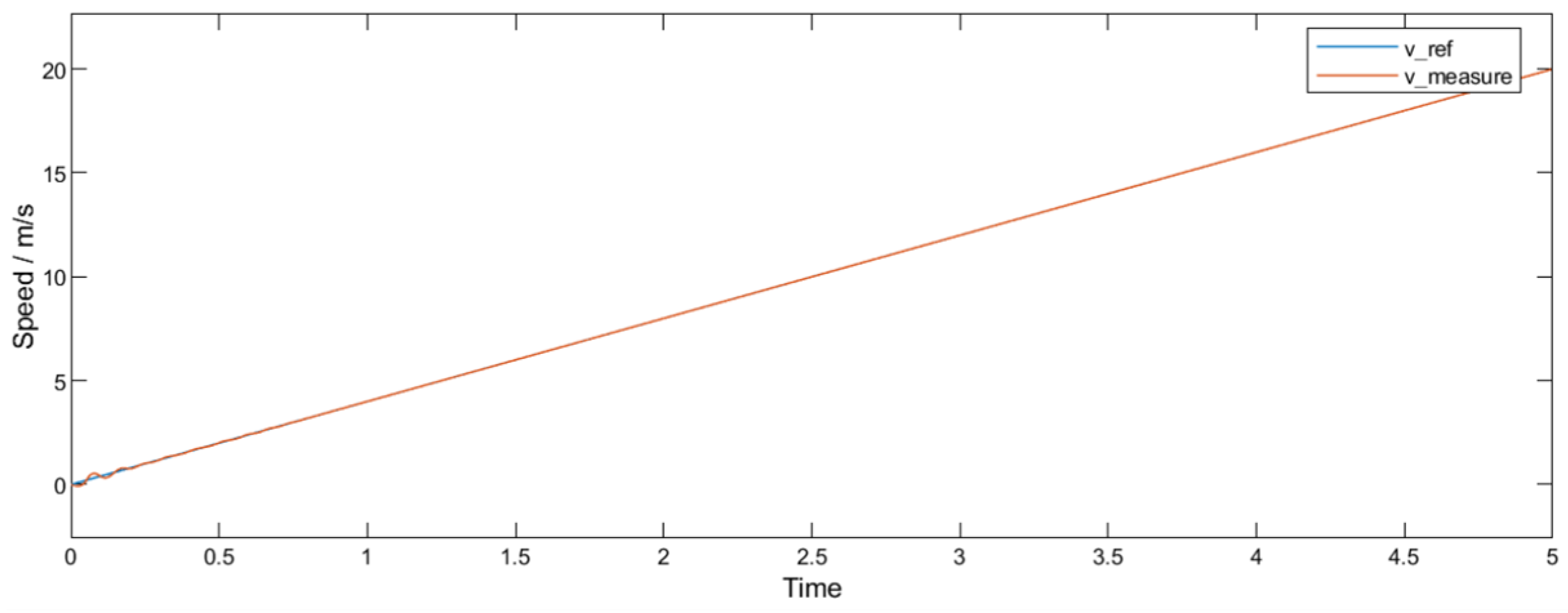
The LIM underwent a 5 s acceleration, with the introduction of the MAC at 2.5 s and the incorporation of a PR controller at 3.5 s. The velocity curve in Figure 7 indicates that the control system effectively tracked the speed signal.
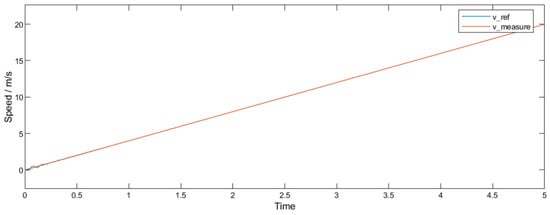
Figure 7.
Simulation result of reference and measured speed.
This paper primarily focuses on the motor acceleration process; hence, the corresponding speed reference values continuously increase. It can be observed that the tracking performance of the speed is quite satisfactory.
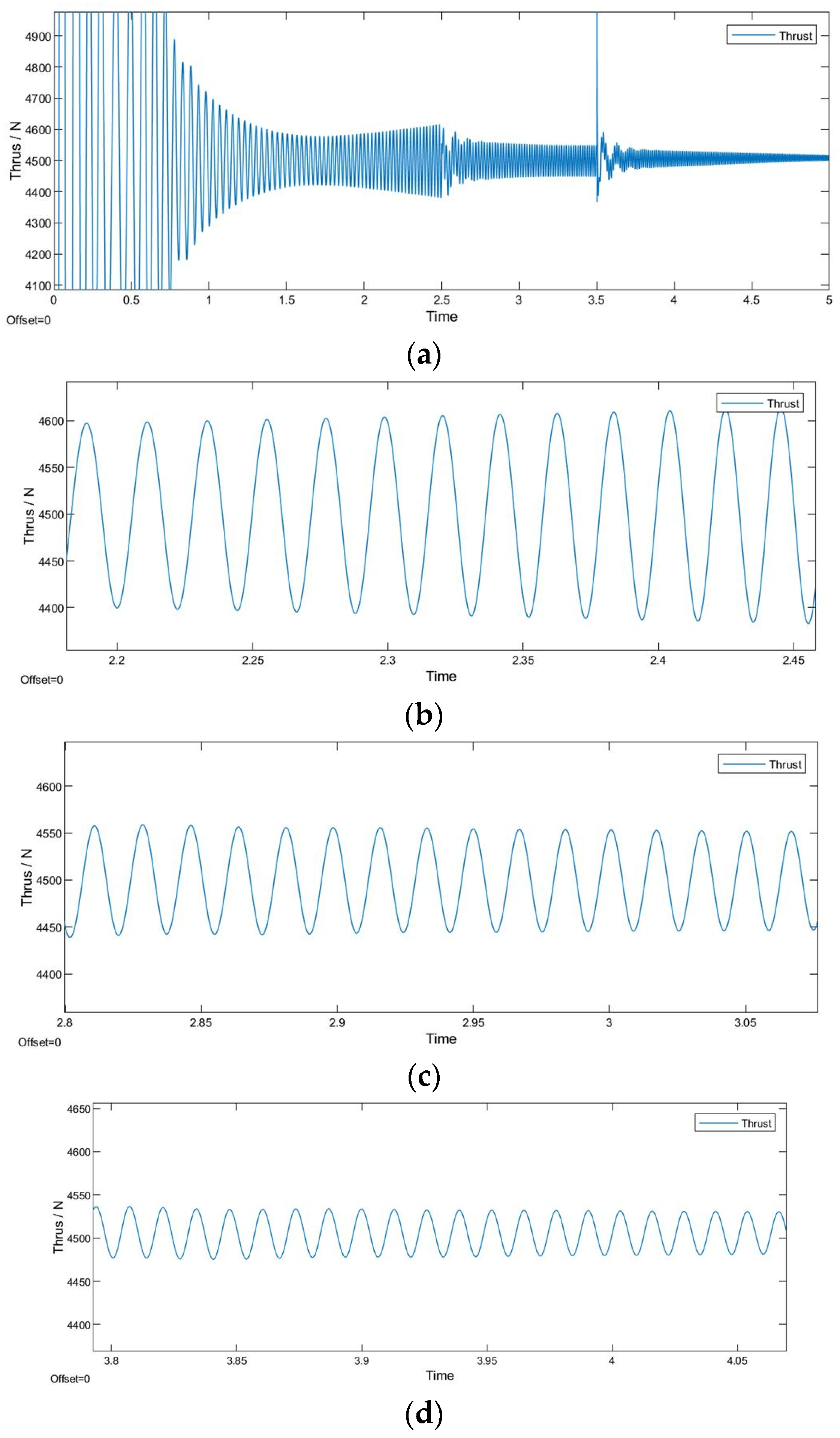
The thrust simulation results shown in Figure 8 are as follows: (a) provides an overview of the thrust results, the MAC is introduced at 2.5 s, and the PR control is added at 3.5 s; (b) presents the magnified thrust results under the original FOC control, showing thrust ripple fluctuating between 4400 N and 4600 N; (c) displays the magnified results of FOC+MAC, demonstrating a reduction in peak-to-peak thrust value to around 100 N; and (d) exhibits the magnified results of FOC+MAC+PR, where the peak-to-peak thrust value is further reduced to 50 N. Additionally, it is evident that the system experiences oscillation around 3.5 s, attributed to the alteration of the PI control’s steady-state behavior upon the introduction of the PR controller. The simulation in this study involves adding the PR control when the PI controller reaches steady state to facilitate the observation of performance enhancement with the PR control. However, in practical applications, controllers are not typically changed during operation; instead, the decision to adopt the PR control is made at the outset.
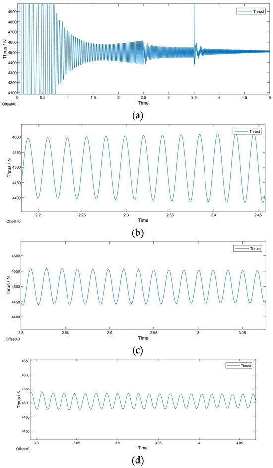
Figure 8.
Thrust simulation results: (a) thrust results overview; (b) thrust results under FOC; (c) thrust results under FOC+MAC; and (d) Thrust results under FOC+MAC+PR.
4.2.2. Current Characteristics Simulation Results
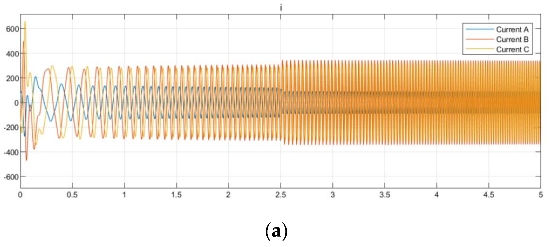
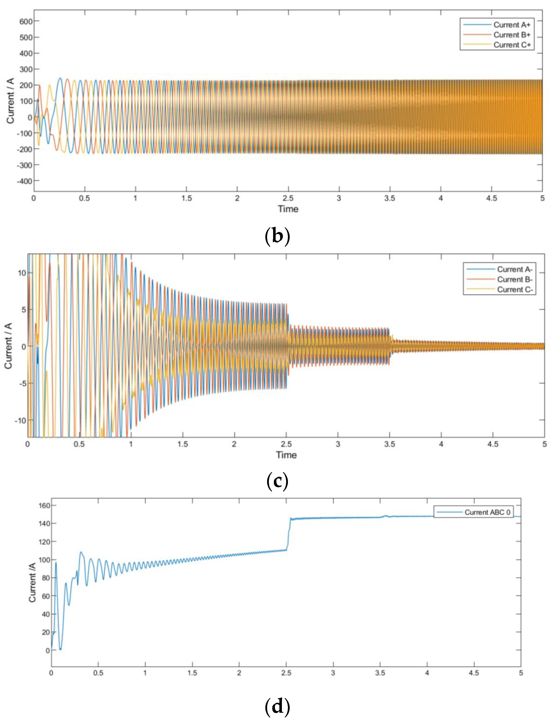
The simulation results of the stator current, including its positive-sequence component, negative-sequence component, and zero-sequence component, are illustrated in Figure 9.
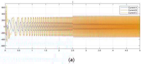
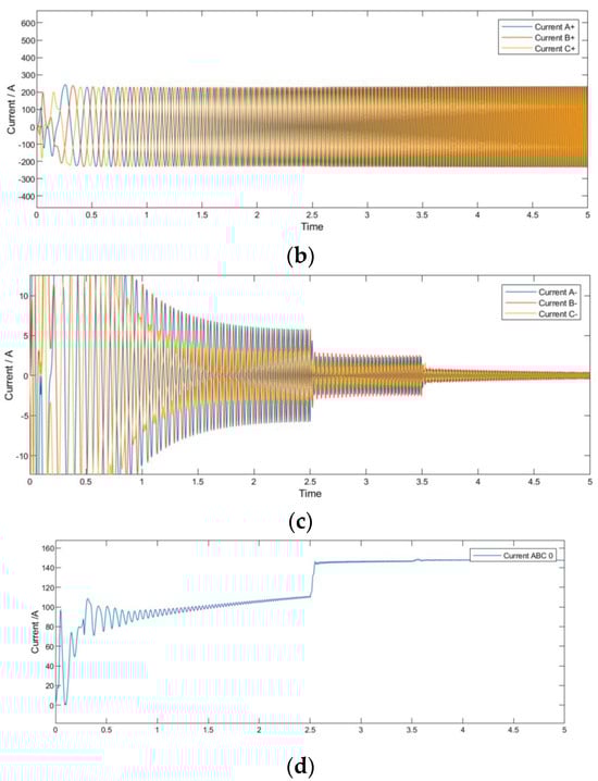
Figure 9.
Current simulation results overview: (a) stator currents; (b) positive-sequence stator currents; (c) negative-sequence stator currents; and (d) zero-sequence stator currents.
In Figure 9, subgraph (a) represents the stator current, while subgraphs (b), (c), and (d) represent the positive-sequence component, negative-sequence component, and zero-sequence component decomposed from the stator current using the orthogonal component method. It can be observed that the positive-sequence current component shows no significant change. It is evident that the negative-sequence current decreases at 2.5 s with the introduction of the MAC and further diminishes at 3.5 s with the implementation of the PR control. Additionally, an increment in the zero-sequence current is observed. However, in the context of this study, no specific analysis has been undertaken for the zero-sequence current due to its negligible impact on thrust ripple.
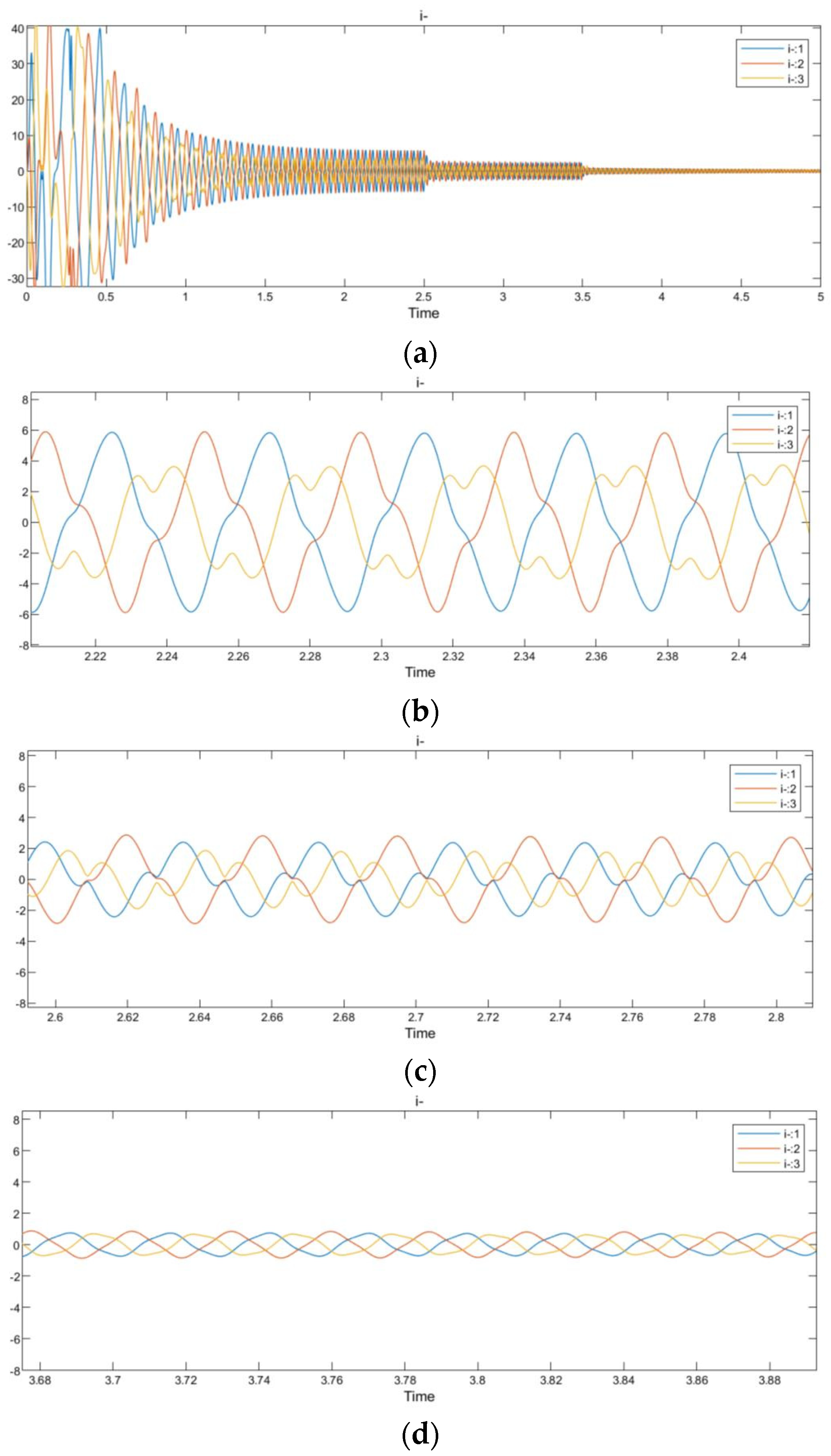
It can be observed from the simulation results that Figure 10 has shown that, after the MAC is introduced at 2.5 s, there is a reduction in negative-sequence current from 6 A to 2 A. At 3.5 s, with the addition of PR control, there is a further reduction in negative-sequence current to approximately 1 A. Based on the depicted graph, it is evident that the waveform of the negative-sequence current is not a conventional sine wave before the integration of the PR controller. We attribute this deviation to the presence of harmonics. The PR controller proves adept at reducing these harmonics. The simulation results for the amplitude of the negative-sequence current are illustrated in Figure 11. The results indicate that both the MAC and PR controllers can effectively reduce the amplitude of the negative sequence current, but that the PR controller excels in eliminating harmonics.
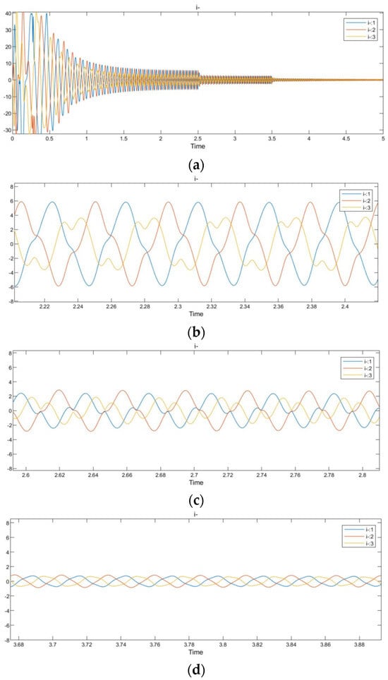
Figure 10.
Negative-sequence current: (a) negative-sequence currents overview; (b) negative-sequence currents under FOC; (c) negative-sequence currents under FOC+MAC; and (d) negative-sequence currents under FOC+MAC+PR.
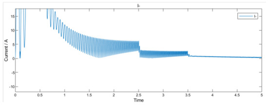
Figure 11.
Amplitude of negative sequence current.
The simulation results for id and iq are shown in Figure 12. In the FOC control system, the controlled variables are id and iq, and the introduction of the PR controller directly aims to mitigate the fluctuations in id and iq.
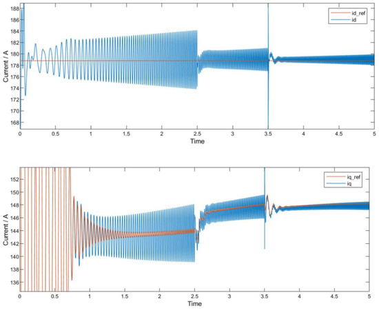
Figure 12.
Simulation results for id and iq.
From Figure 12, it can be observed that the addition of both the MAC and PR significantly reduces the harmonics in both and . It can be observed that at 3.5 s, the system experienced some instability, which was caused by the introduction of the PR controller. It is important to emphasize that the simulation involved adding the PR controller during the runtime to compare the effects introduced by the PR controller. However, in actual operation, the PR controller should be added at the beginning of the runtime.
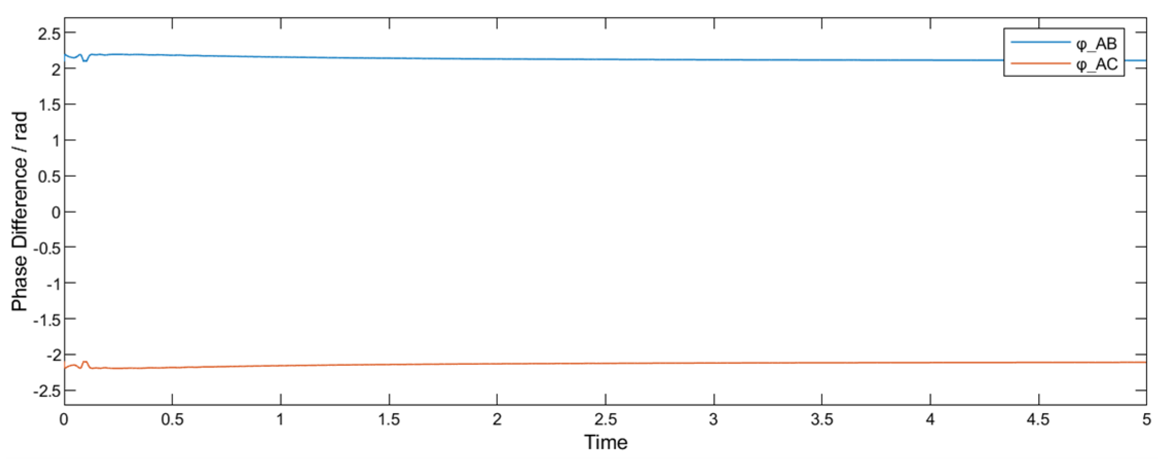
Figure 13 shows that the difference in the voltage phase calculated by the MAC module is approximately 2.2 rad, i.e., 126.5°; however, when the MAC is not used, the difference in the voltage phase is 120°.
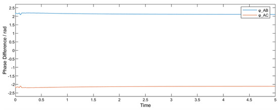
Figure 13.
Phase calculation results.
In conclusion, based on the simulation and experimental results, the proposed MAC can effectively reduce the thrust ripple by altering the voltage phase. Furthermore, with the incorporation of the quasi-PR controller, the suppression of the thrust ripple is further enhanced. Simulation results also indicate that the suppression of the thrust ripple is related to the reduction in both the current harmonics in the axis and the negative-sequence component of the stator current.
5. Experimental Physical Test and Validation
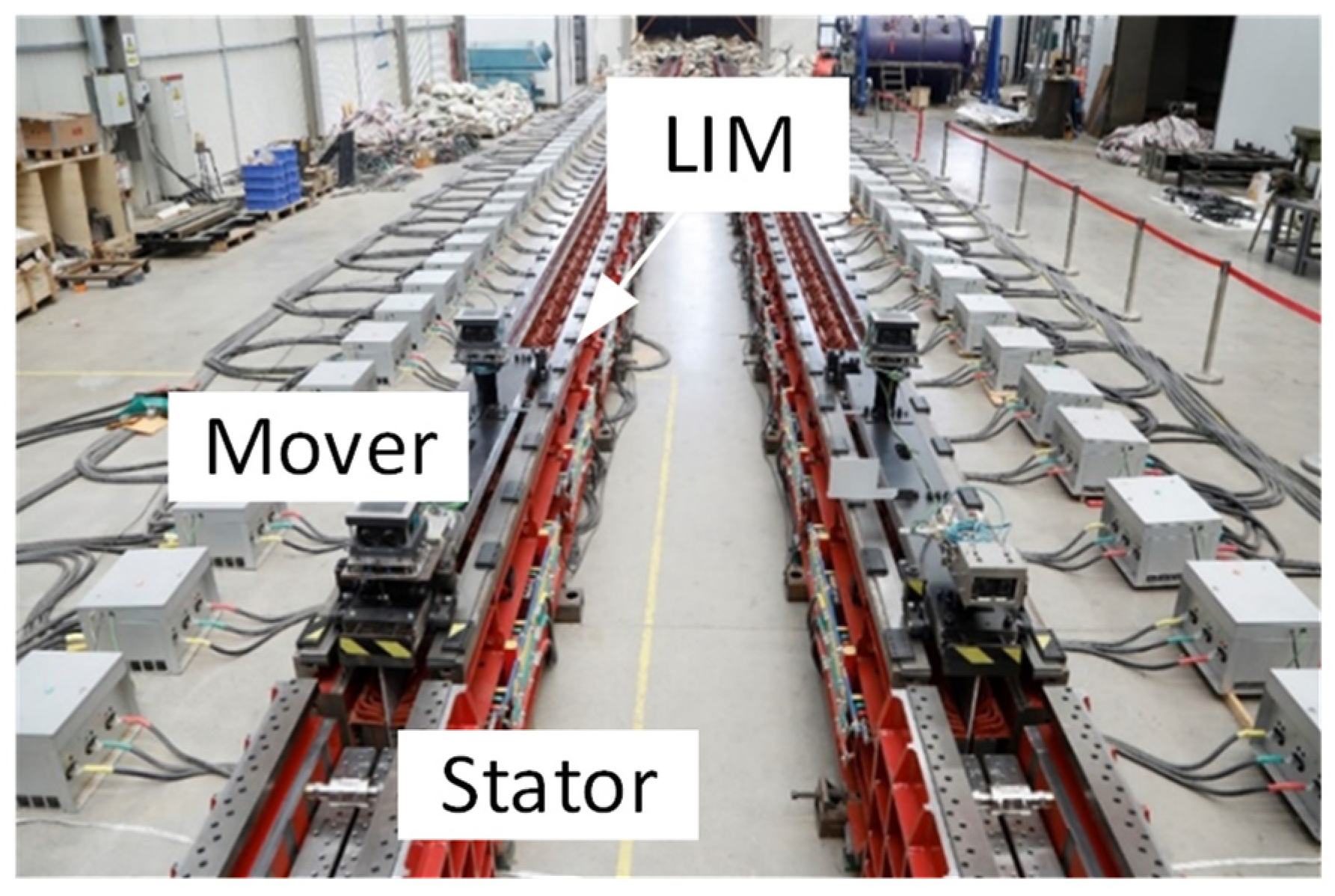
To validate the effectiveness of the simulation results, physical experiments were conducted on the platform shown in Figure 14. The experimental platform consists of a double-sided primary induction linear motor, with the stator and mover depicted in the figure. The LIM depicted in Figure 14 is a long-stator LIM that operates using segmented power supply.
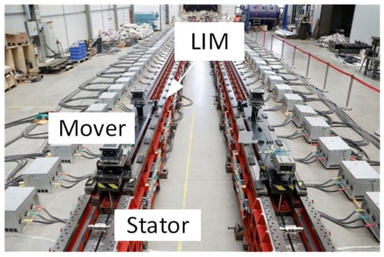
Figure 14.
LIM experimental platform.
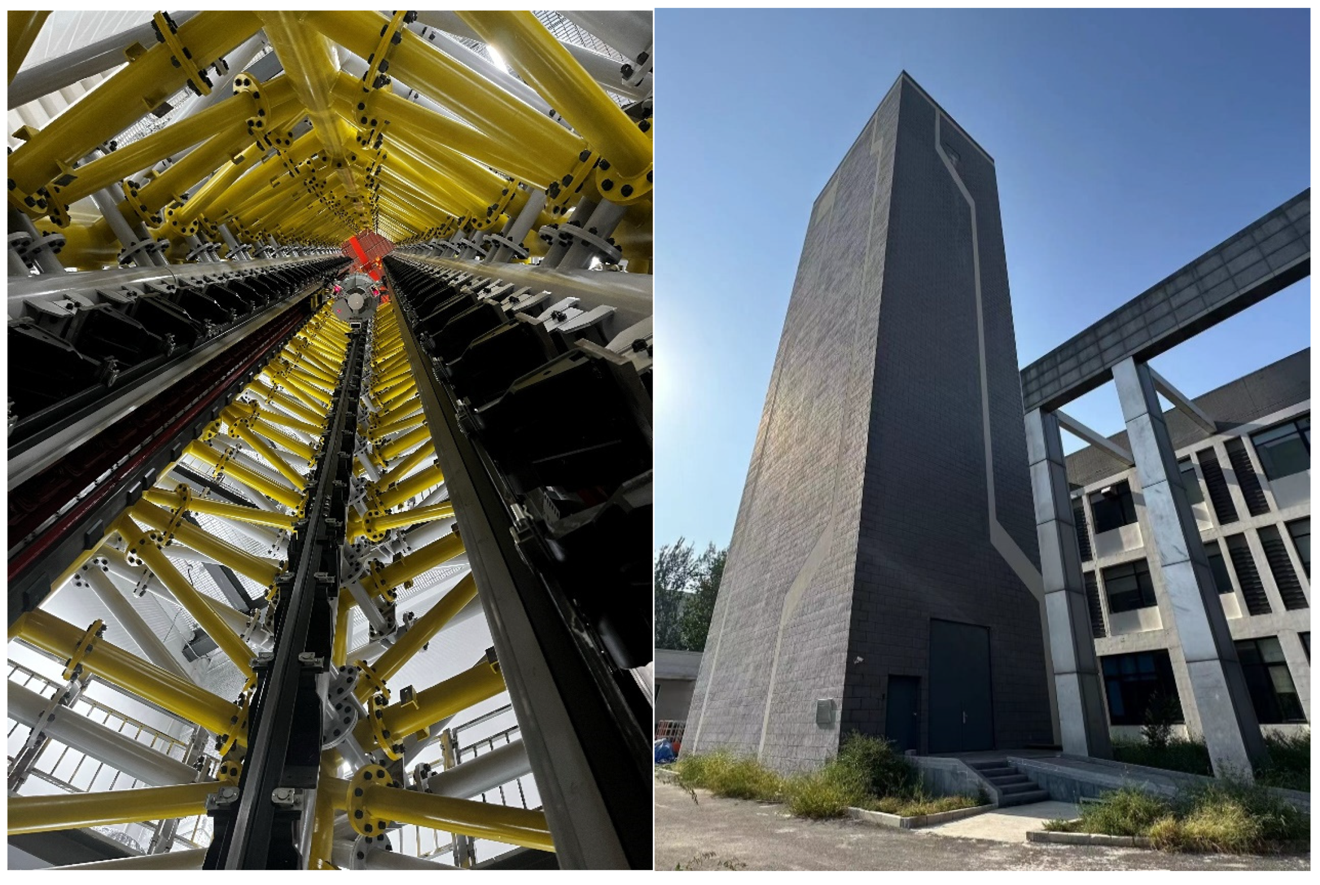
We also conducted experiments using the MEFEL device as Figure 15 shows, which utilizes a motor with the same parameters as those employed in the horizontal experimental platform. The difference is that the motor in this facility operates vertically. The experimental capsule is driven by two LIMs, with the mover installed on the outer side of the experimental capsule and the stator mounted on the inner wall of the tower. Additionally, rails are installed to ensure the directional movement of the experimental capsule. Each operation involves launching the experimental capsule upward using the LIM, allowing the experimental capsule to undergo free-fall motion, and then retrieving it. This study primarily focuses on the launch phase, but in the actual testing environment, the launch, free-fall, and recovery phases are conducted together.
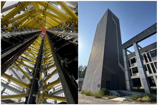
Figure 15.
MEFEL experimental platform with vertical LIM.
The design parameters of the LIM used in both of these experimental platforms are the same, but improvements are made to the manufacturing process; this results in the LIM exhibiting a slightly better performance in MEFEL. The design parameters of the LIM are shown in Table 3.
Table 3.
LIM parameters.
5.1. Experimental Results in the Horizontal Experimental Platform
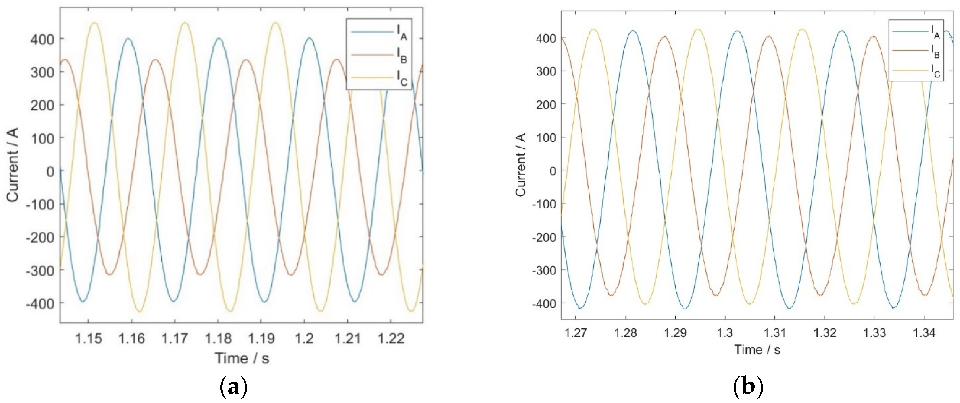
Due to the limitations that existed in the experimental environment, we only conducted tests under blocked conditions on the horizontal platform and obtained the following current results. The experimental results of the stator current before and after the utilization of the MAC and PR controller are shown in Figure 16.
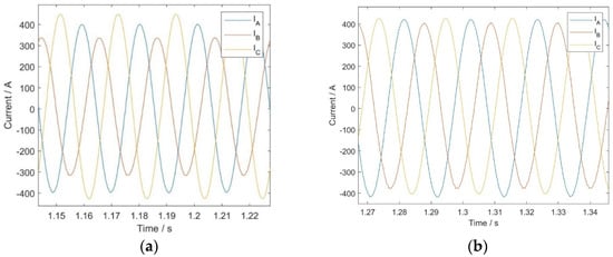
Figure 16.
Stator current: (a) no compensation method; (b) MAC and PR employed.
The experimental results indicate that the peak stator currents for the three phases before the use of MAC and quasi-PR controllers were 392.5 A, 320.1 A, and 451.6 A, respectively. After applying the MAC and quasi-PR controllers, the peak stator currents for the three phases were 410.7 A, 395.4 A, and 417.7 A, respectively. The three-phase current imbalance decreased from 29.1% to 5.28%, indicating a significant reduction in current imbalance. The experimental results demonstrate that the adoption of the MAC and quasi-PR controllers can effectively reduce the current imbalance in the stator, leading to the LIM exhibiting an improved performance.
5.2. Experimental Results in the MEFEL Platform
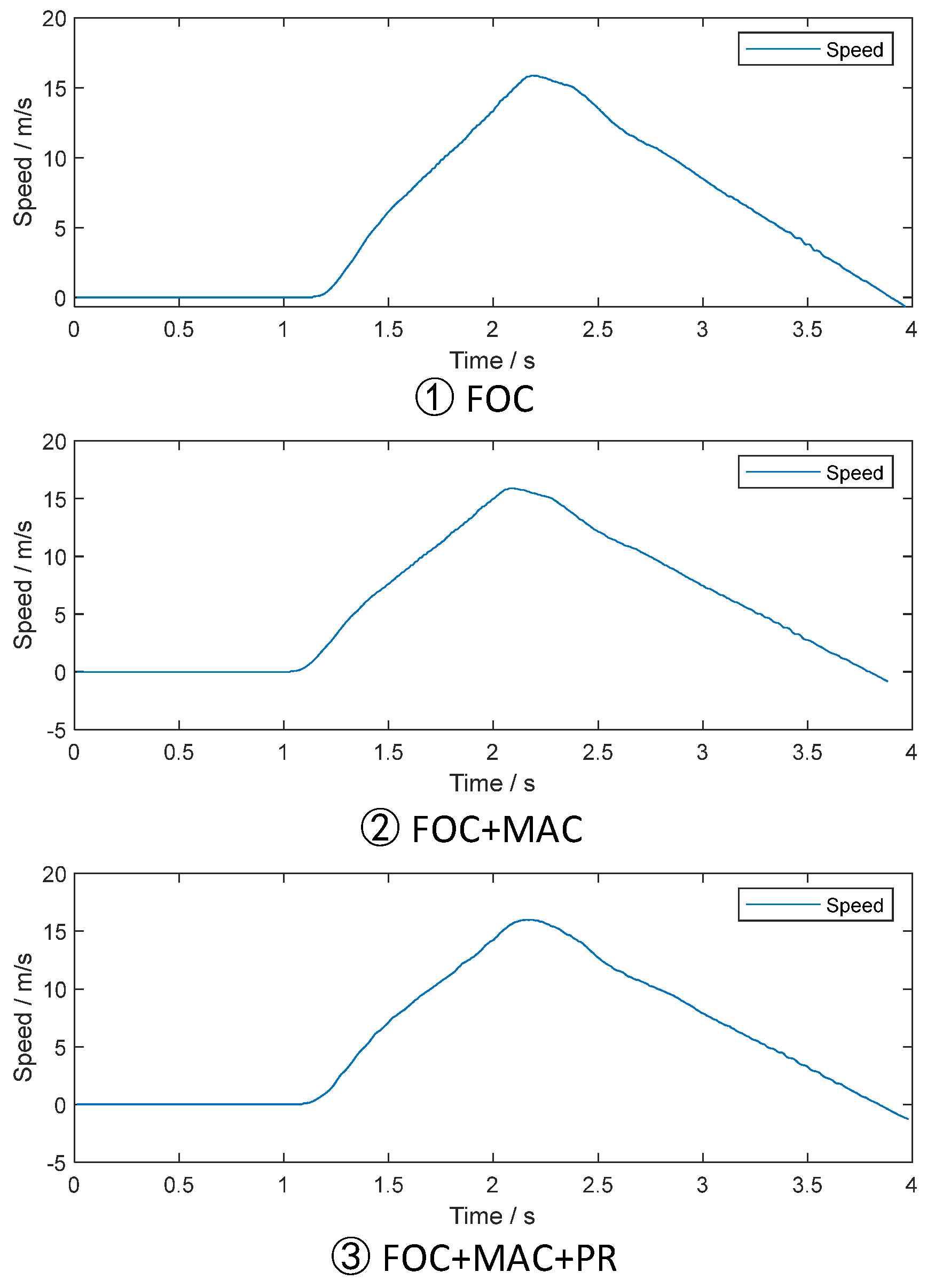
In the MEFEL platform, we conducted three sets of comparative dynamic experiments. The first group utilized the FOC control system, the second group employed the FOC+MAC system, and the third group utilized the FOC+MAC+PR system. Our objective was to observe the improvements in thrust brought about by the proposed methods; however, direct measurement of the thrust of the linear motor was challenging to achieve. We could only calculate the acceleration by processing the velocity signals, thereby indirectly observing the optimization of thrust fluctuations. The experimental results regarding the velocity are shown in Figure 17.
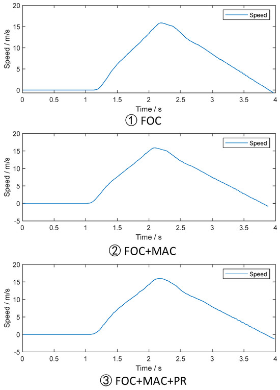
Figure 17.
Speed results of MEFEL.
The operation requirements of the electromagnetic microgravity facility studied in this paper dictate a specific speed profile, meaning that regardless of changes in the motor-controlled current loop, we aim for the speed loop to remain consistent. The results of the speed operation are shown in Figure 17, where it can be observed that under different control methods, the tracking of the speed loop is similar, ultimately meeting the system’s performance requirements. Specifically, the performance of the current loop can be indirectly observed by observing the acceleration. Direct measurement of thrust in linear motors is challenging; hence, this study indirectly observes thrust and thrust ripples by measuring the acceleration of the experimental capsule using an accelerometer. The differentiation of speed in Figure 17 is roughly equivalent to the acceleration in Figure 18, but the signals in Figure 17 and Figure 18 are measured by different sensors. The speed results in Figure 17 are derived from the differentiation of the position signal obtained by the grating displacement sensor, while acceleration is directly measured using an accelerometer.
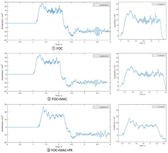
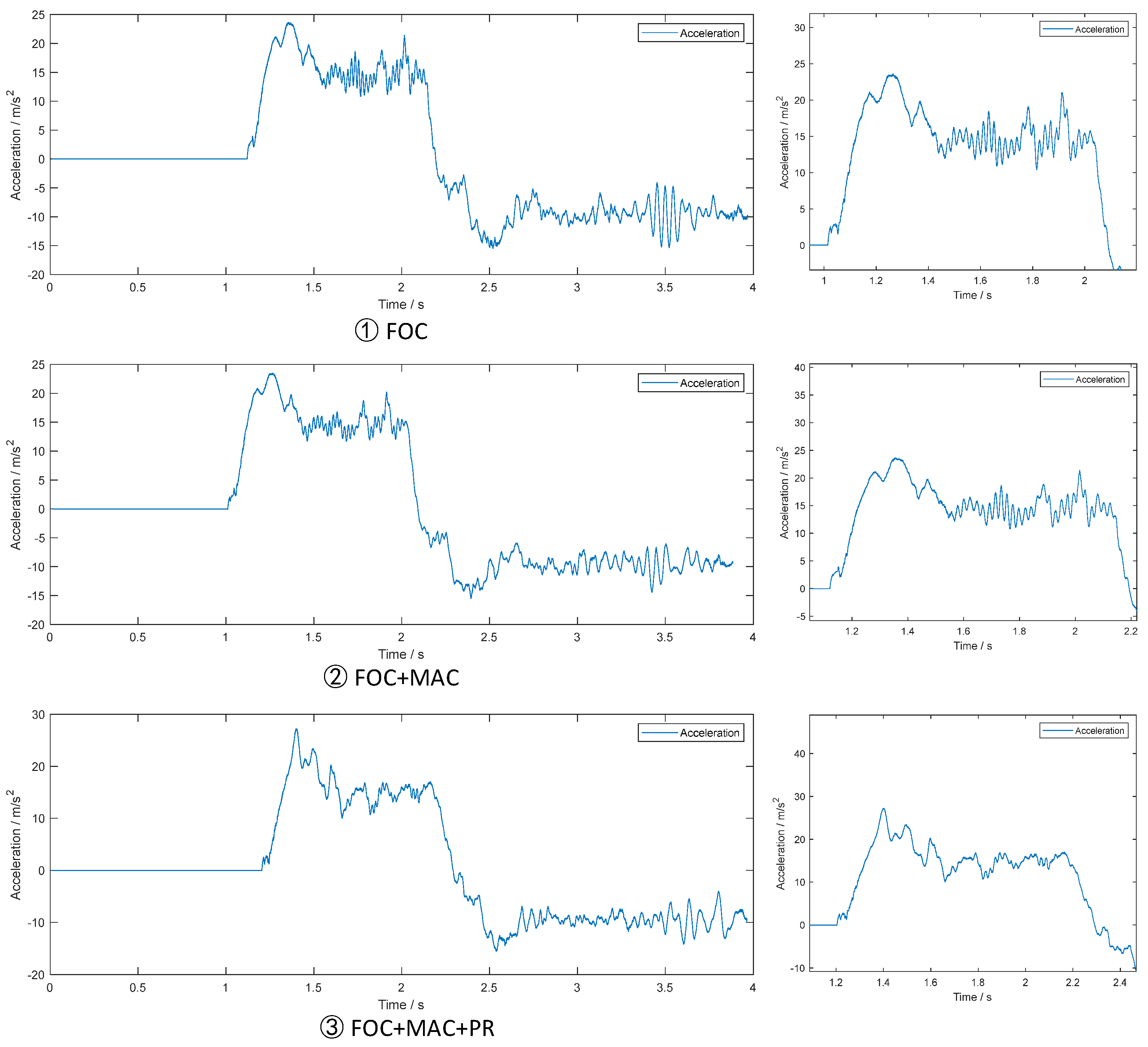
Figure 18.
Acceleration results of MEFEL.
It can be observed from the acceleration results that, under FOC, the acceleration fluctuates at approximately 5 m/s2. Building upon this, the utilization of the MAC reduces the acceleration fluctuation to around 3.5 m/s2, and further implementing the PR control narrows the acceleration fluctuation to approximately 2 m/s2. It is important to note that the system also encounters other disruptive forces, such as mechanical friction, air resistance, and mechanical vibrations. The vibration reduction method proposed in this paper solely focuses on suppressing the fluctuations caused by LIM thrust. Vibrations originating from the mechanical structure within the experimental environment require mechanical damping solutions, which can be achieved via the modification of the construction design. The processed acceleration data can provide insights into the thrust fluctuations observed in the linear motor. Utilizing the MAC and PR controls individually can partially suppress the thrust ripple, but the most effective suppression of thrust fluctuation is achieved when both the MAC and PR controls are employed simultaneously. It is worth noting that the accuracy of the acceleration data is constrained, as it is derived from velocity signals through differentiation and filtering. Therefore, the extent of acceleration fluctuation is closely related to the level of filtering applied.
The motor in the actual test environment belongs to a catapult system, and the operation process is divided into catapult stage, free fall stage, and recovery stage. The research content of this paper mainly focuses on the launch section, but the experimental results show the free fall stage and the recovery stage as well. In simulation we can simulate only the catapult stage. In the simulation results, the two control methods proposed in this paper are added in the operation process, while in the actual test environment, it is impossible to add the controller in the operation process to compare the control effect, and many experiments are needed.
Through the comparison of the acceleration results of the actual test and the thrust results of the simulation, it can be seen that the actual acceleration has a very low frequency and a high amplitude fluctuation, which is caused by the segmented stator. This part of the fluctuation can also be improved by optimizing the segmented control strategy, but it is not the focus of this study. This paper mainly studies the elimination of the thrust ripple caused by the physical characteristics of the linear motor itself. Additionally, it can be observed that there are many irregular interferences in the thrust of the actual operation, which may be from the mechanical vibration in the environment or the friction of the guide rail, etc., while the thrust ripple in the simulation is only caused by the physical characteristics of the linear motor. Although there are many differences between physical testing and simulation testing, the effectiveness of the method proposed in this article can still be seen from the actual test results.
6. Conclusions
This study addresses the challenge of the thrust ripple in a high-power LIM for the microgravity facility. It introduces a model-based adaptive controller (MAC) and an enhanced quasi-proportional-resonant (PR) controller for current control, taking into account the impedance asymmetry inherent in LIMs. The MAC adjusts the voltage phase to counteract the current imbalance that results from the LIM’s impedance asymmetry. The improved quasi-PR controller, in tandem with the PI controller, works to eliminate harmonics in the current d-q axis. The comprehensive theoretical derivations and calculation methods employed for both control strategies are thoroughly examined. Simulation results indicate that after adopting the MAC to correct the current phase, the thrust ripple decreases to 50%. A further reduction to 25% is achieved by implementing the PR controller to correct the current amplitude. The experimental results demonstrate the effectiveness of the method proposed in this paper in practical engineering applications.
Author Contributions
Conceptualization, Y.L. and W.D.; Methodology, Y.L.; Software, Z.W.; Validation, Y.L.; Investigation, Y.L. and W.D.; Resources, W.D., C.L. and Y.Z.; Data curation, Z.W.; Writing—original draft, Y.L.; Writing—review & editing, Y.L., W.D. and Z.W.; Visualization, Z.W.; Supervision, C.L. and Y.Z.; Project administration, C.L. and Y.Z.; Funding acquisition, Y.Z. All authors have read and agreed to the published version of the manuscript.
Funding
This research was funded by the Chinese Manned Space Program—Space Utilization System (412021000031), Scientific Instruments and Equipment Development Program of the Chinese Academy of Sciences (YJKYYQ20180017) (YJKYYQ20210028), and the Youth Innovation Promotion Association CAS.
Data Availability Statement
The data presented in this study are available in this article.
Conflicts of Interest
The authors declare no conflict of interest.
Appendix A
Inductance Equivalent Expression of LIMs
The model of a rotary motor can be expressed as follows:
in which L satisfies
In the matrix of , , and represent the self-inductances of the stator windings. , and other inductances in the matrix represent the mutual inductance of the stator windings.
The self-inductance consists of leakage inductance and main self-inductance.
Due to the intentional design of a electrical angular difference between windings, the mutual inductances satisfy the following relationship:
The steady-state model of motor is commonly analyzed using the T-type equivalent circuit model, as shown in Figure A1.

Figure A1.
T-type equivalent circuit.
Figure A1.
T-type equivalent circuit.
It reflects the voltage–current relationship on the single-phase winding, where the excitation inductance is equal to .
Up to this point, we have observed an interesting phenomenon: in the magnetic flux linkage equation, the voltage of the single-phase winding is related to the currents of other windings, while in the T-type equivalent circuit, it seems to be only related to the current of the winding itself. This is because in three-phase motors, sinusoidal currents have a 120° phase difference, allowing the inductance matrix to be transformed into a diagonal matrix through calculation. (A reminder: the calculation of excitation inductance is independent of the rotor, as the motor inherently functions as a transformer model. After winding transformation calculation, the excitation inductance of the rotor is equal to that of the stator. In other words, the circuit model parameters on the rotor side are not equivalent to the magnetic flux model parameters, so we do not analyze the rotor-side magnetic flux.)
In phase A, the stator flux caused by stator current can be expressed as follows:
The calculation process for phases B and C is the same as that for phase A. In this case the can be expressed as
However, in a LIM the impedance matrix cannot be transformed into a diagonal matrix due to the asymmetry of the impedance. Even when the currents are balanced, can only be expressed as follows:
The calculation process for phases B and C is the same as that for phase A. Thus of the three-phase windings in the equivalent circuit cannot be expressed as one parameter. The equations for the three-phase excitation inductances are as follows:
In this case, the can be expressed as
It should be noted that this expression is based on the steady-state model of motor, assuming the motor speed changes smoothly.
Appendix B
Demonstration of the Effect of MAC for Current Imbalance Correction
The MAC can be represented as follows:
As , , and are sinusoidal three-phase waves which can be represented as
where is amplitude, is angular velocity and t is time.
Based on the above equations, it can be calculated that:
Hence, when and , .
The AC waveforms and can be represented using vectors:

Figure A2.
Voltage vectors.
Figure A2.
Voltage vectors.
Hence

Figure A3.
Voltage vectors and current vectors.
Figure A3.
Voltage vectors and current vectors.
define which satisfies the following relationship:
The voltage phase difference of phase A and phase B satisfies the following:
Then, calculate the phase difference of currents phase A and phase B:
Hence, the phase difference is . By using the same method, the phase difference between and can be calculated to be −.
Thereby, we can conclude that the phase difference of , , and is , after balancing correction.
Additionally, it can be observed that the current imbalance has only been fixed in terms of phase deviation, while the amplitude deviation still exists. In the control system under FOC, the currents and can reflect the problem of unequal current amplitudes, and dynamic control can be applied for adjustment. This is described in Section 3 of this paper, where it is achieved through a PI+PR controller.
References
- Könemann, T.; Kaczmarczik, U.; Gierse, A.; Greif, A.; Lutz, T.; Mawn, S.; Siemer, J.; Eigenbrod, C.; von Kampen, P.; Lämmerzahl, C. Concept for a next-generation drop tower system. Adv. Space Res. 2015, 55, 1728–1733. [Google Scholar] [CrossRef]
- Zhang, J.; Dong, W.; Wang, Z.; Zhang, Y.; Zhang, X.; Cai, Z.; Ma, W.; Li, Y.; Li, X.; Cui, X. Development of a New Microgravity Experiment Facility with Electromagnetic Launch. Microgravity Sci. Technol. 2021, 33, 1–18. [Google Scholar] [CrossRef]
- Li, Y.; Dong, W.; Zhang, S.; Zhang, Y. A Prototype of Microgravity Facility Operated by Linear Motors: Motion Plan and Control. In Proceedings of the IAF Microgravity Sciences and Processes Symposium, International Astronautical Congress 2020, Washington, DC, USA, 12–14 October 2020. [Google Scholar]
- Zhao, J.; Wang, S.; Liu, Q.; He, Z.; Zhang, W.; Li, K.; Zhou, Z.; Luo, X.; Miao, J.; Zheng, H.; et al. Retrospect and Perspective on Microgravity Science in China. Chin. J. Space Sci. 2021, 41, 34–45. [Google Scholar] [CrossRef]
- Nasar, S.A.; Boldea, I. Linear Motion Electric Machine; John Wiley & Sons Inc.: Hoboken, NJ, USA, 1976; pp. W43–W56. [Google Scholar]
- Long, X. Theory and Electromagnetic Design for Linear Induction Motor; Press of Science: Beijing, China, 2006; pp. 67–72. [Google Scholar]
- Nie, S.; Fu, L.; Xu, J.; Li, W.; Sun, Z. Asymmetrical Model and Parameter Calculation of Segment-powered Linear Inductive Motor Mover. J. Electr. Mach. Control. 2017, 21, 10–17. [Google Scholar]
- Lu, J.; Ma, W.; Li, L. Research on Longitudinal End Effect of High-speed Long Primary Double-sided Linear Induction Motor. Proc. CSEE 2008, 28, 73–78. [Google Scholar]
- Sun, Z.; Liu, D.; Ma, W.; Lu, J.; Xu, J. Research of Static Longitudinal End Effect and Impedance Matrix for Long Primary Double-sided Linear Induction Motors. Proc. Chin. Soc. Electr. Eng. 2010, 30, 1–6. [Google Scholar]
- Lv, G.; Cui, L.; Zhi, R. Inductance Analysis of Transverse Flux Linear Synchronous Motor for Maglev Trains Considering Three-Dimensional Operating Conditions. IEEE Trans. Ind. Electron. 2024, 71, 769–776. [Google Scholar] [CrossRef]
- Duncan, J. Linear induction motor—Equivalent-circuit model. Proc. Inst. Electr. Eng. 1983, 130, 51–57. [Google Scholar]
- Xu, W.; Zhu, J.G.; Zhang, Y.; Li, Z.; Li, Y.; Wang, Y.; Guo, Y.; Li, Y. Equivalent circuits for single-sided linear induction motors. IEEE Trans. Ind. Appl. 2010, 46, 2410–2423. [Google Scholar] [CrossRef]
- Xu, W.; Zhu, J.G.; Zhang, Y.; Li, Y.; Wang, Y.; Guo, Y. An improved equivalent circuits of a single-sided linear induction motor. IEEE Trans. Veh. Technol. 2010, 59, 2277–2289. [Google Scholar] [CrossRef]
- Sun, Z.; Gao, J.; Ma, W.; Lu, J.; Xu, J. Impedance Matrix and Parameters Measurement Research for Long Primary Double-Sided Linear Induction Motor. IEEE Trans. Plasma Sci. 2019, 47, 2703–2709. [Google Scholar] [CrossRef]
- Lu, J.; Ma, W. Investigation of Phase Unbalance Characteristics in the Linear Induction Coil Launcher. IEEE Trans. Plasma Sci. 2011, 39, 110–115. [Google Scholar] [CrossRef]
- Han, Z.; Xu, J.; Rui, W.; Zhang, Y.; Li, M. Research on Thrust Ripple of Aperiodic Transient Linear Induction Motors. In Proceedings of the 2021 13th International Symposium on Linear Drives for Industry Applications (LDIA), Wuhan, China, 1–3 July 2021; pp. 1–5. [Google Scholar]
- Liu, H.; Wang, Y.; Zhang, Q.; Zhang, Z.; Song, T. Optimization of Thrust Ripple of Long Primary Double Sided Linear Induction Motor Injected with Harmonic Current. J. Electr. Mach. Control 2023, 27, 49–60. [Google Scholar]
- Zhou, W.; Sun, Z.; Zeng, R.; Mao, Y.; Ding, A. A Thrust Ripple Suppression Method for Long-Primary Double-Sided Linear Induction Motors Based on Harmonic Current Injection. IEEE Trans. Transp. Electrif. 2023, 9, 2348–2355. [Google Scholar] [CrossRef]
- Sun, X.; Xu, J.; Zhu, J.; Xu, W. Thrust Ripple Suppression Based on Negative Current Control for Short-Primary Low-Speed Large LIM Under Transient Operation. IEEE Trans. Energy Convers. 2023, 38, 1566–1575. [Google Scholar] [CrossRef]
- Wang, K.; Li, Y.; Ge, Q.; Shi, L. An Improved Indirect Field-Oriented Control Scheme for Linear Induction Motor Traction Drives. IEEE Trans. Ind. Electron. 2018, 65, 9928–9937. [Google Scholar] [CrossRef]
- Gu, H.; Cai, Z.; Wang, Z.; Zhang, Y.; Dong, W.; Guo, R. Three-Phase Current Unbalance Suppression Method of Linear Induction Motor Based on PR Controller. In Proceedings of the 2022 4th International Conference on Smart Power & Internet Energy Systems (SPIES), Beijing, China, 27–30 October 2022; pp. 883–888. [Google Scholar]
- Cui, D.; Wei, R.; Liu, J.; Ge, Q. Linear synchronous motor drive system based on proportion resonant current controller in maglev transportation. In Proceedings of the 2014 17th International Conference on Electrical Machines and Systems (ICEMS), Hangzhou, China, 22–25 October 2014; pp. 1289–1292. [Google Scholar]


Disclaimer/Publisher’s Note: The statements, opinions and data contained in all publications are solely those of the individual author(s) and contributor(s) and not of MDPI and/or the editor(s). MDPI and/or the editor(s) disclaim responsibility for any injury to people or property resulting from any ideas, methods, instructions or products referred to in the content. |
© 2024 by the authors. Licensee MDPI, Basel, Switzerland. This article is an open access article distributed under the terms and conditions of the Creative Commons Attribution (CC BY) license (https://creativecommons.org/licenses/by/4.0/).