Abstract
A novel self-adaptive bilateral control strategy is introduced to manage uncertainties inherent in the teleoperation of an underwater manipulator system effectively. In response to uncertainties stemming from both the mathematical model and external disturbances, our approach offers innovative solutions. Firstly, to address uncertainties in the master model parameters, we propose a reference adaptive impedance control based on a nominal model. This control strategy dynamically adjusts the reference position of the desired model, leveraging adaptive control laws to compensate for model uncertainties. Additionally, to tackle uncertainties specific to the slave manipulator, we employ adaptive compensation using radial basis function (RBF) networks. Our unique combination of sliding mode variable structure controllers and robust adaptive controllers aims to mitigate approximation errors, ensuring precise tracking of the master manipulator’s position by the slave manipulator. By employing Lyapunov function analysis, we demonstrate the system’s superior tracking performance and global stability, with assured asymptotic convergence for force–position tracking. Through comprehensive experimentation, our results showcase the exceptional force–position tracking capabilities of the overall control system, even under challenging conditions of model uncertainties and external disturbances. Moreover, our system exhibits remarkable stability, reliability, and robustness, underscoring the effectiveness of our proposed adaptive control approach.
1. Introduction
In the process of underwater environment detection [1], the complexity and high danger of the seabed environment make manual underwater operations challenging [2]. The autonomous underwater vehicle-manipulator system used for assistance in underwater operations not only it improves efficiency but also ensures the safety of underwater workers [3]. The underwater vehicle typically uses a manipulator to perform tasks such as opening and closing valves, underwater welding, and cutting underwater cables during underwater operations [4]. Currently, the operation of the autonomous underwater vehicle-manipulator system faces various challenges [5]. The widely applied approach is to utilize teleoperation technology to assist remotely in underwater tasks. An underwater teleoperation system generally consists of an operator, the master manipulator for operation, a communication channel, the remotely operated slave manipulator on the underwater side, and the underwater working environment [6]. The operator generates and sends force or position commands to the master manipulator, and the master manipulator controller transmits the force and position information through the communication channel to the remotely operated slave manipulator. The remotely operated robotic arm completes underwater tasks by tracking the position information from the master manipulator [7].
In order to improve the stability and transparency of the underwater teleoperation system, force feedback is introduced into the underwater teleoperation system [8]. The force signal sensed by the end of the underwater manipulator is transmitted to the master manipulator through the force sensor at the end, so that the operator can perceive the interactive force of the underwater working environment, which improves the operator’s sense of presence during underwater operations, reduces work errors, and improves the efficiency of underwater operations. The application of force feedback in master–slave manipulators in underwater teleoperation systems is particularly significant in tasks such as underwater mine clearance, explosive ordnance disposal, and obstacle clearance. It eliminates the need for operators to be present in hazardous areas, thereby reducing the risk of personnel casualties. Additionally, it combines the advanced intelligence of humans and the scalability of robots, overcomes distance limitations, and improves operating efficiency and control performance.
The teleoperation of underwater manipulators faces a series of challenges and problems, including but not limited to dynamic uncertainty, external uncertain disturbance, and communication time delay [9]. The complexity of the underwater environment causes the manipulator system to face a large number of uncertainties, including changes in water flow, seabed topography, and variations in material properties [10]. These factors make it difficult for traditional control methods to deal with uncertainty. External disturbances that may exist in the underwater environment, such as changes in water flow and water pressure, may interfere with the movement and positioning of the manipulator and affect the accuracy and stability of remote teleoperation [11]. There is the time-delay problem in underwater communications, which may cause control delays and reduce the responsiveness of the system for remote operations with high real-time requirements. The robot is a time-varying, strongly coupled multi-input multi-output nonlinear system, and uncertainty is inevitable in practical applications [12]. Therefore, under the premise of ensuring the stability of the overall system, uncertainty teleoperation control improves transparency and robustness, and enables position and force signals to be reproduced synchronously on the slave manipulator and the master manipulator, which is still the overall control goal.
In the teleoperation system, the master manipulator can be regarded as a force feedback device that reproduces the standard force signals and provides position tracking signals to the slave manipulator. The slave manipulator can be regarded as a position tracking robot system that is in contact with the external environment and has limited movement constraints. Due to the requirement of underwater teleoperation systems, the master manipulator is typically installed within a surface vessel, while the underwater slave manipulator is commonly situated on a remotely operated vehicle (ROV) or an autonomous underwater vehicle (AUV). The data communication distance between the master and slave manipulators is relatively short. In addition, 5G communications can increase the communication rate and reduce the communication time delay. Therefore, the communication delay can be ignored. At this time, the decisive influence on the control law design of the underwater robot teleoperation system is the uncertainty of the manipulator model caused by external uncertain disturbance and joint friction.
In order to solve the problems of model uncertainty and external disturbance in teleoperation control, many scholars have proposed different control methods. Numerous effective control schemes, including the adaptive bilateral control method [13,14], predictive control [15,16], optimal control [17], intelligent control based on fuzzy logic [12,18] or neural networks [19,20], prescribed-performance-based control [21,22], etc., have been developed for bilateral teleoperation systems in recent years. The adaptive neural network controller with an adaptive time-delay estimator and parameter adaptive method is designed for the precise position tracking in the teleoperation system under communication constraints [14]. The adaptive dynamic surface control strategy with an observer-based adaptive fuzzy synchronization framework is proposed for teleoperation systems with the time-delay derivative in [9]. In [23], a dynamical force observer was introduced for teleoperations, based on the prescribed performance functions. Aiming at the problem of unmeasurable speed and uncertain dynamics, Yana Yang designed a robust sliding mode control based on a speed observer with neural network uncertainty compensation [24], which realized the force position synchronization of master and slave. Majtaba proposed an adaptive bilateral control method for the manipulator dynamics uncertainty [25], and applied it to the medical equipment teleoperation process [26], but the uncertainty caused by external disturbance is not considered [27]. What is more, Parham M proposed a robust adaptive scheme that effectively deals with time-varying delay and uncertainties in teleoperation systems. For the problem of position tracking in teleoperation systems subject to external forces, Bahareh Aboutalebian designed an adaptive control algorithm and adaptive laws based on a nonlinear disturbance observer in order to address the tracking error caused by external forces and dynamic uncertainty in the teleoperation systems [28]. In paper [29], two sliding-mode observers with a novel power-reaching law are proposed to deal with the uncertainties of teleoperation systems, and the finite time convergence of the tracking errors can be realized with the proposed observers. Longnan Li proposed an adaptive neural learning fixed-time control scheme incorporating an integral barrier Lyapunov function to achieve the master and slave position tracking, and the neural networks are utilized to reconstruct environmental forces and approximate the total uncertainty of the robot [30]. Hang Li proposed an adaptive fuzzy neural network backstepping control scheme for bilateral teleoperation systems with asymmetric time delays to achieve consistent synchronization of master–slave manipulator positions [11]. Parham proposed an adaptive interval type-2 fuzzy neural network control scheme for teleoperation systems with time-varying delays and uncertainties; the stability and performance of the proposed control was analyzed using the Lyapunov-Krasovskii method [27].
Hongjiu Yang proposed a continuous terminal sliding mode control (CTSMC) strategy based on an extended state observer (ESO) and a time-delay part observer to achieve the master and slave position tracking performance in bilateral teleoperation systems [31]. Yanna Yang proposed the synchronization control problem of an uncertain single-master multislave (SMMS) teleoperation system, in which every subsystem is connected with each other via a directed constrained communication network [32]. In paper [11], the synchronization tracking control issue is investigated for uncertain teleoperation systems with input saturation and output error constraints. Hang Li proposed an adaptive fuzzy neural network backstepping control scheme for bilateral teleoperation systems with asymmetric time delays induced by the communication links and various uncertainties [11]. These control algorithms achieve the purpose of coordinated and consistent synchronization of bilateral force and position by overcoming external uncertain disturbance or mathematical model uncertainty caused by internal uncertainty [33].
This paper presents an innovative adaptive bilateral control strategy to address the challenges posed by uncertainty in the motion model of master–slave manipulators and external disturbances during remote operations of underwater manipulators. To tackle uncertainties in both model parameters and motion characteristics of the master manipulator, we introduce a reference adaptive impedance control based on the nominal model. This approach employs adaptive control laws to compensate for model uncertainty, facilitating accurate force representation by the operator on the master manipulator and an interaction force between the slave manipulator and the environment. Addressing uncertainties in the slave manipulator, we utilize an RBF network to approximate the uncertain model components. The sliding mode variable structure controller and adaptive controller are then employed to eliminate approximation errors, ensuring a consistent, stable, and bounded position tracking error of the slave manipulator relative to the master manipulator. Furthermore, the control stability is rigorously proven through Lyapunov function analysis.
The remain of this paper is arranged as below. In Section 2, both kinematic and dynamic models of the dual manipulators are introduced, and the corresponding manipulator properties are also introduced. In Section 3, the overall structure design of the bilateral robust adaptive impedance controller is achieved, and the master adaptive impedance controller and slave adaptive neural network control are designed in detail using Lyapunov-based stability theory. The simulation verification of a two-degrees-of-freedom (DOF) teleoperation system is completed in Section 4. In Section 5, an experimental setup of a single-degree-of-freedom (DOF) teleoperation system is established to validate the force and position tracking performance of the dual manipulators with the designed controller. The experimental results provide evidence of the effectiveness of the proposed controller in achieving the desired force and position coordination during teleoperation. Finally, in Section 6, the main conclusions of the study are presented, summarizing the findings and contributions of the research.
2. Mathematical Model and Basic Properties
The joint space nonlinear dynamic model of the n-link master–slave manipulators can be described as [34]:
where ; represents the identification of the master and slave manipulators; , , and represent the position, velocity, and acceleration of the joints in the master and slave manipulators; and , , , , and are, respectively, denoted as the inertia, the sum of centrifugal force and Coriolis force, gravity term, friction torque and Jacobian matrix. represents the force exerted by the operator on the master manipulator and denotes the interaction force between the slave manipulator and the operating object. The disturbance torque of indicates the bounded uncertainty of the external disturbance of the slave manipulator. It is assumed that and can be measurable with the tactile force sensor. It is supposed that and are generated from the internal joint friction, which can be formulated as , where and represent the sticky coefficient and the Cullen coefficient, respectively. The sticky coefficient, , denotes the viscous friction in the joints space, while the Cullen coefficient, , denotes the Coulomb friction in the joint space.
To achieve force and position tracking in Cartesian coordinates, the dynamics of the dual manipulator in the joint space are transformed and expressed in the operation space:
where is the position vector of master and slave manipulator end-effectors in the task space; represent the mapping relationship between the joint space and task space of the dual manipulators; and the joint space velocity, , is described as [25]:
Assuming that the manipulator joint is non-redundant, the Jacobian matrix, , can be expressed as:
According to Equation (1), the relationship between joint acceleration and acceleration in task space is described by:
According to Equations (4) and (5), and can be concluded and combining with the joint dynamic model, Equation (1), and the dynamic model based on task space can be obtained [25]:
The relations of the dynamic matrices between the joint space and the task space with the non-singular Jacobian matrices, , can be concluded as [25]:
The master and slave manipulators possess the following properties [35]:
- Property 1.
- The inertia matrix and of the manipulator are positive definite;
- Property 2.
- and are, respectively, skew-symmetric matrices.
- Property 3.
- According to different unknown parameters, the manipulator dynamics can be linearized as:where ; represents the identification of the master and slave manipulators; , is any known vector; the regressor matrix is a regression matrix function known for the parameters containing joint space information in terms of the arbitrary vectors and ; and is the unknown parameters of the manipulator.
The slave manipulator tracks the motion of the master manipulator, which can be divided into free space motion and motion with limited contact with the environment. Considering only the influence of the movement position on , when the manipulator is in contact with the environment, the force on the environment can be regarded as a passive linear spring, and the contact force, , can be expressed as [36]:
where represents the position of the slave manipulator and the contact environment, and represents the stiffness coefficient of the grasping target. When , the movement of the master hand and the slave hand is in a free space state; at , the slave manipulator can be seen contacting the environment, generating a tactile force.
3. Overall Control Strategy
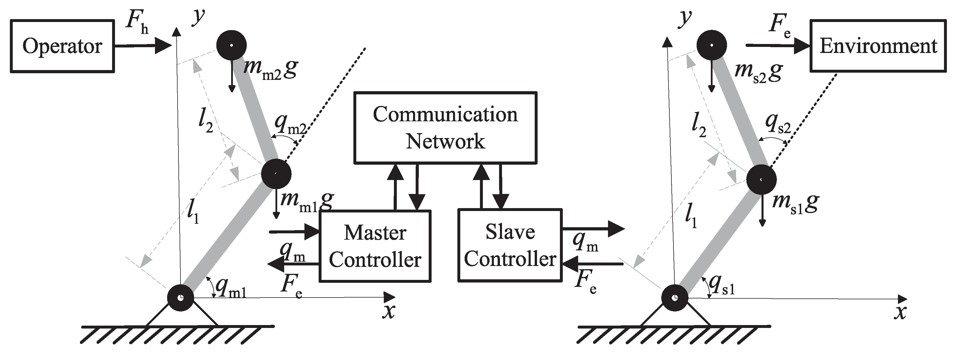
The overall schematic diagram of the teleoperation manipulator system is shown in Figure 1. A planar two-link rotating manipulator is employed as the research object of the teleoperation manipulator. It is assumed that the master and slave manipulators have the same linkage structure. The operator exerts force on the master manipulator, and the master manipulator moves according to the applied force. The master manipulator controller transmits the master position to the slave manipulator via the communication network, and the slave controller obtains the master manipulator position information as the slave position tracking target. The slave hand completes position tracking and transmits the slave manipulator and external environmental forces to the master manipulator. The master manipulator achieves consistent matching between the operator’s applied force and the slave manipulator’s force, meeting the force–position consistency of the master–slave manipulator and realizing the operator’s purpose to perceive truly the tactile force of the slave side.
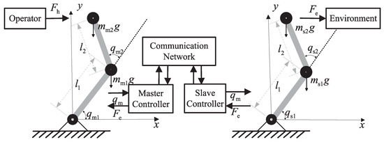
Figure 1.
Overall diagram of teleoperation manipulator.
In order to solve the problem of uncertain parameters of the manipulator dynamic model and external interference, the adaptive impedance control for the master manipulator force tracking and the adaptive sliding mode neural network control for the slave manipulator position tracking were designed to achieve the force and position tracking of the dual manipulators, respectively.
4. Adaptive Force Tracking Control of the Master Manipulator
The impedance control adjusts the target impedance model set by the user to achieve the goal of flexible motion for the manipulator’s terminal. By adding adaptive features to impedance control, the master manipulator’s tactile force tracking performance becomes robust under external uncertain conditions [37]. A second-order mathematical model can be established between the operator’s master manipulator force, the slave manipulator force, the master terminal velocity, and acceleration. The designed model is considered as the target impedance model. In order to track the environmental contact force exerted by the operator, the impedance control model is expressed as [38]:
where the matrices and are the target impedance parameters, which are the desired inertia and damping matrix of the manipulator, respectively; is the contact force between the slave manipulator and the environment; is the force exerted by the operator on the master manipulator; and is the output reference position of the target impedance model in the Cartesian coordinate system. In the second-order model of the target impedance, the reference position, , is obtained by the error between the master force, , and the environment force, , as the master manipulator position tracking target, and the matching of the manipulator position to achieve the matching of the grasp and environmental power. When the system is in a steady state, can be obtained, and, at the same time, and are zero, which satisfies the impedance relation, Equation (10), for balance. The master model refers to the adaptive impedance control structure diagram shown in Figure 2.
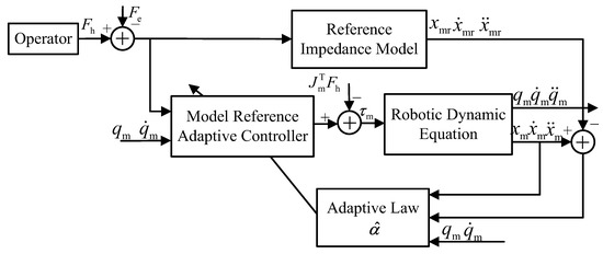
Figure 2.
The structure of the master adaptive impedance control.
Since the dynamic equation of the master manipulator is a nonlinear second-order system, in order to realize the location of the manipulator’s operating space, is expected to reference position tracking of the master manipulator, and the design is:
where is a positive diagonal matrix, and define , is the difference between the end position, , of the master manipulator and the expected reference position, . Define the reference speed vector:
From Equations (11) and (12), it can be obtained: . The control law for the master manipulator is designed as follows in the Cartesian coordinate system:
Because the real model parameters of the master manipulator cannot be obtained, , , , and are the corresponding estimates of the number of master manipulator parameters, respectively. The control law of the design angle coordinate system, then the control law of Equation (13) in the joint coordinate system, correspond to:
Equation (14) can be expressed as:
The joint angles and lengths of the manipulator are known, so the Jacobian matrix, , is a known quantity. and in Equation (15) are known vectors, which are as follows:
Referring to manipulator Property 3, the control law, Equation (15), can be expressed as:
where is the regression matrix derived from the linearization of the manipulator dynamic model, Equation (1), is the estimated value of the uncertain parameter, and the adaptive law is designed as:
where is a positive definite diagonal matrix. Substituting the control law, Equation (17), into the manipulator dynamics model, Equation (1), and, according to manipulator model Property 3, the closed-loop control system with the master adaptive control law can be expressed as:
where represents the error between the uncertainty estimation value and the real value. is a constant vector, and can be obtained. The master manipulator can be regarded as a force feedback device, and the stability of the master manipulator should be ensured with the adaptive controller. In order to prove that the stability of the master manipulator and the force tracking error tend to zero, the Lyapunov function, , is designed as:
Due to the positiveness of and , can obviously be obtained.
Taking the first derivative of with respect to time, and combining equations , Equations (18) and (19), with Property 2, we can conclude:
According to Equation (21), it is known that . With the Lyapunov stability theorem, the controller ensures the global stability of the master manipulator system as , , thereby achieving . Therefore, the master manipulator position, , is gradually converged at the reference position, , of the impedance model under the condition of the desired impedance model with Equation (11).
5. Slave Manipulator Adaptive Position Tracking Control
The master manipulator is generally located on a ship or in an underwater operating submersible, and the slave manipulator is generally fixed on an underwater vehicle such as a cabled underwater robot or an autonomous underwater robot. The distance between the master and the slave is relatively close, so the impact of the master–slave manipulator controller communication time delay on the system is ignored. The slave manipulator is equivalent to the position tracking of the tracking position standard signal, and transmits the force signal of the interaction between the slave manipulator and the environment to the master manipulator for force tracking. For external tracking under external uncertainty conditions of the slave hand, an adaptive slave hand controller is designed, including an RBF neural network compensator, sliding mode control, and adaptive control law. The utilization of the online learning algorithm for the RBF neural network, as detailed in [39], demonstrates robust self-learning and self-organizing capabilities. This approach can effectively learn external disturbances in complex environments, accurately approximate intricate models, and mitigate the impact of disturbances on the motion of underwater manipulator systems.
The control objective for the slave manipulator is to achieve as using the adaptive controller. Assuming the tactile force of the slave manipulator is measurable, the controller is devised employing the calculated torque method. The position error between the slave manipulator and the master manipulator is denoted as . Additionally, , where represents the reference variable for angular position tracking, and is a positive definite diagonal matrix. The sliding mode variable is defined as follows:
Combining the dynamics of the slave manipulator given by Equations (1) and (22), we obtain:
where , and . Utilizing the RBF neural network to approximate the function , we can express as . Here, W is the neural network weight matrix, represents the basis function, and is the approximation error of the exact model. The estimated value of is given by . Equation (23) can be written as follows:
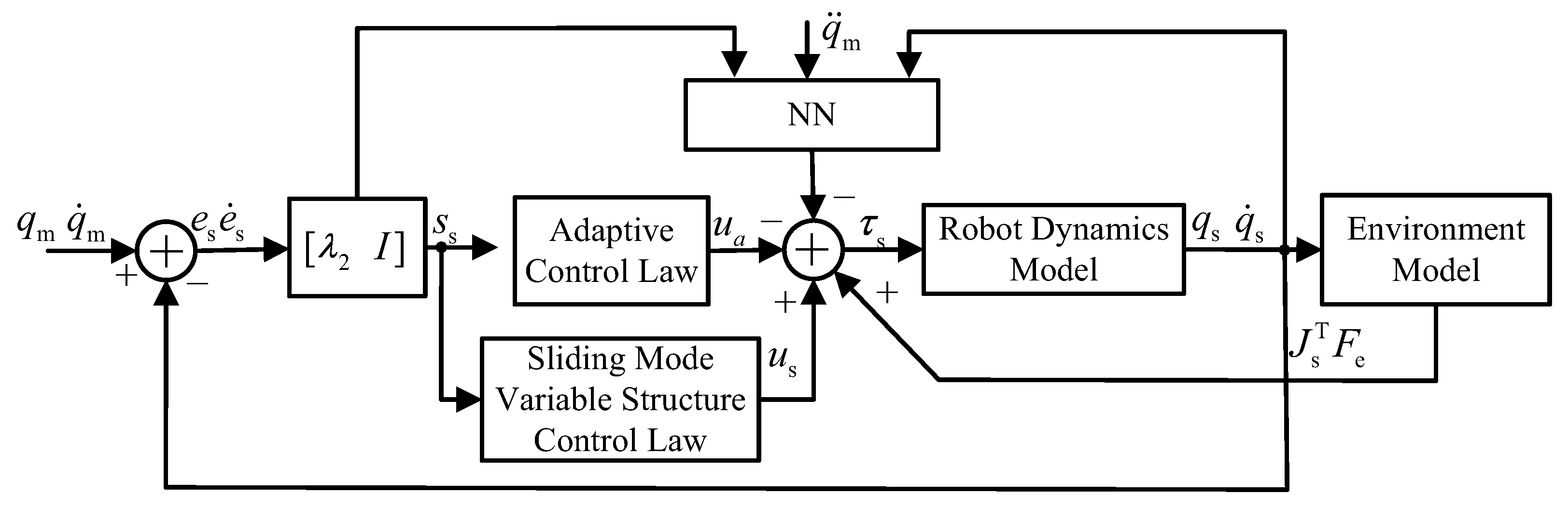
Among them, represents the weight error. According to Equation (24), denotes the torque exerted by the contact force between the slave manipulator and the environment on the slave manipulator. is the sliding mode variable structure control law, and , where and are positive definite diagonal moment arrays. is the regulation law of neural network control, , with the adaptive law of given by , where Q is a positive definite matrix. is a robust adaptive control law, used to overcome neural network approximation errors and system uncertainty, thereby improving robustness. Take , and the adaptive law is as follows: . The overall control is illustrated in Figure 3.

Figure 3.
The control structure diagram of the slave manipulator.
By substituting the control law, , into the dynamic of the slave manipulator, the closed-loop equation can be obtained, as shown in Equation (25).
To establish the stability of the tracking of the slave manipulator in the presence of adaptive control law, we will utilize the Lyapunov function. Let us assume that the Lyapunov function, , for the slave manipulator system is given by:
where represents the trace of the matrix, and is the upper boundary of . Since and are positive definite matrices, it is straightforward to establish that . Finding the derivative of with respect to time, and considering Equation (25) derived from the closed-loop system of the slave manipulator, we can obtain:
Equation (27) is derived from the adaptive law of robotic Property 2, involving the variables and :
Points from 0 to on both sides of Equation (28) can be obtained:
Equation (29) can be rewritten as:
Since and , there are:
From Equation (31), it can be concluded that, as , , and the position tracking error, , along with the error change rate, , gradually converge to 0. The tracking error in the slave manipulator controller caused by parameter uncertainties and external disturbances is compensated using RBF neural networks. Furthermore, the controller achieves robustness through sliding mode control and adaptive laws.
6. Simulation and Verification
According to the system model of the master and slave manipulators and the control requirements, simulations were conducted on the Matlab Simulink platform. The simulations considered the uncertainty of the mechanical power model and external disturbance of the mechanical model of the manipulator, while neglecting the impact of the carrier in the underwater manipulator on the posture. The master manipulator was set up in the vertical plane. For the mathematical model, based on references [40,41,42], the impedance model parameters are defined as follows: , , , and . The masses of the master manipulator are specified as kg and kg, and the lengths are m and m. The initial positions of the master manipulator are set as rad and rad.
In the slave manipulator system, the parameters of the RBF network are set as follows: Gaussian basis function center , width , sliding mode coefficient , and . The controller input gains are and , and the uncertain upper bound estimate for the initial value is .
For the slave manipulator, the masses are specified as kg and kg, and the lengths are m and m. The initial positions of the slave manipulator are set as rad and rad. The environmental stiffness coefficient is configured as , and the slave manipulator is in contact with the grasping target at a distance of m in the x-axis direction. Both master and slave manipulators have internal joint friction described by , with relevant parameters and . The uncertain disturbance inputs for the master manipulator and the slave manipulator are specified as and , respectively.
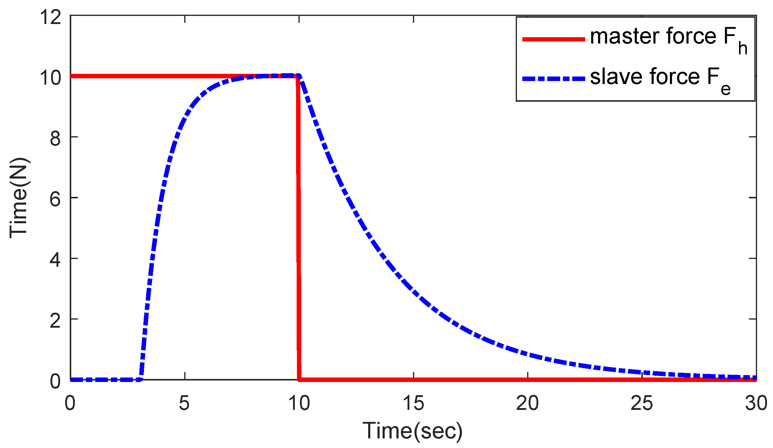
The simulation time is set to 30 s, with a 10 s application of 10 N force on the master manipulator, followed by 0 N force for the remaining 20 s. This setup allows observation of the force–displacement tracking status of the manipulator.
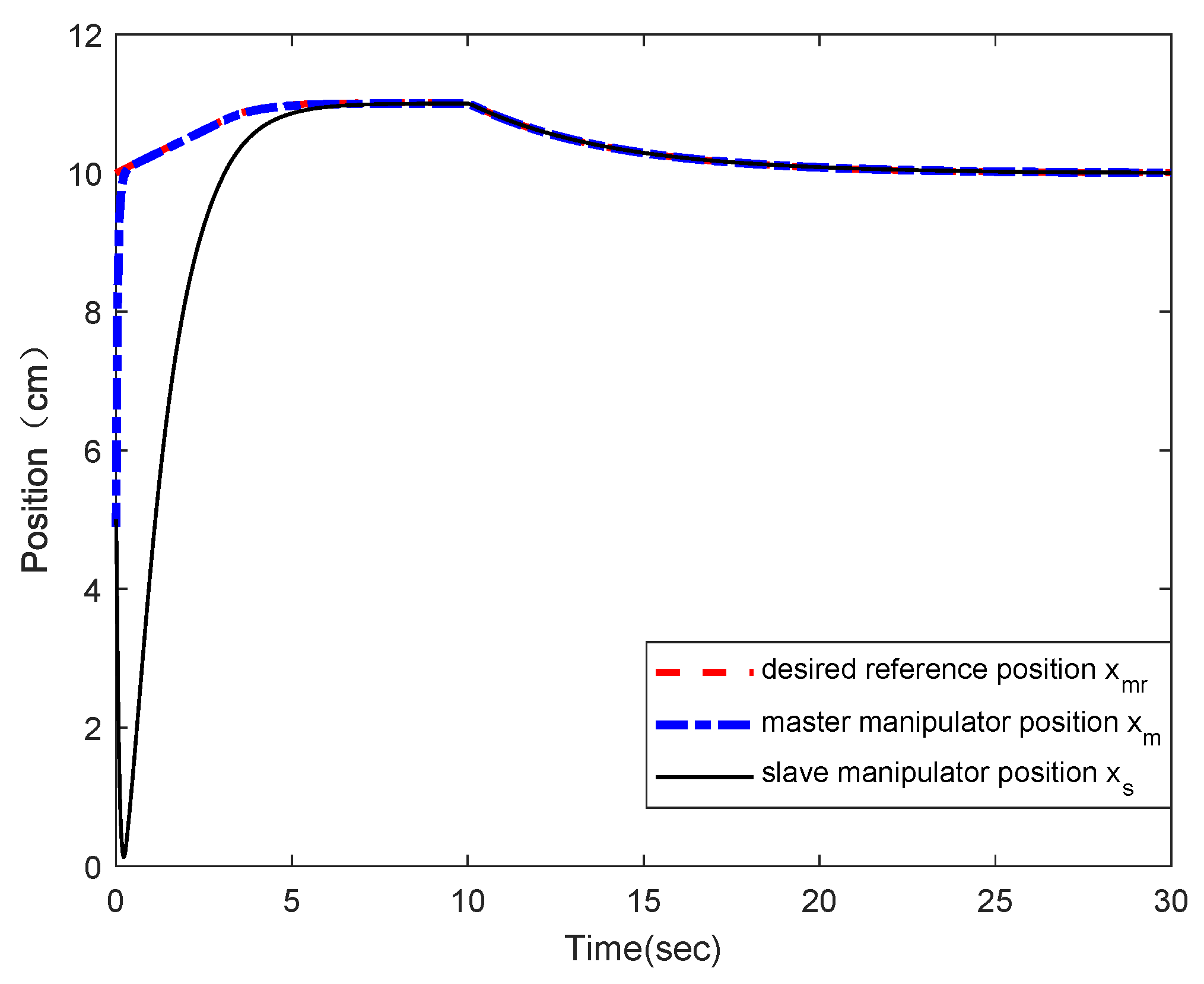
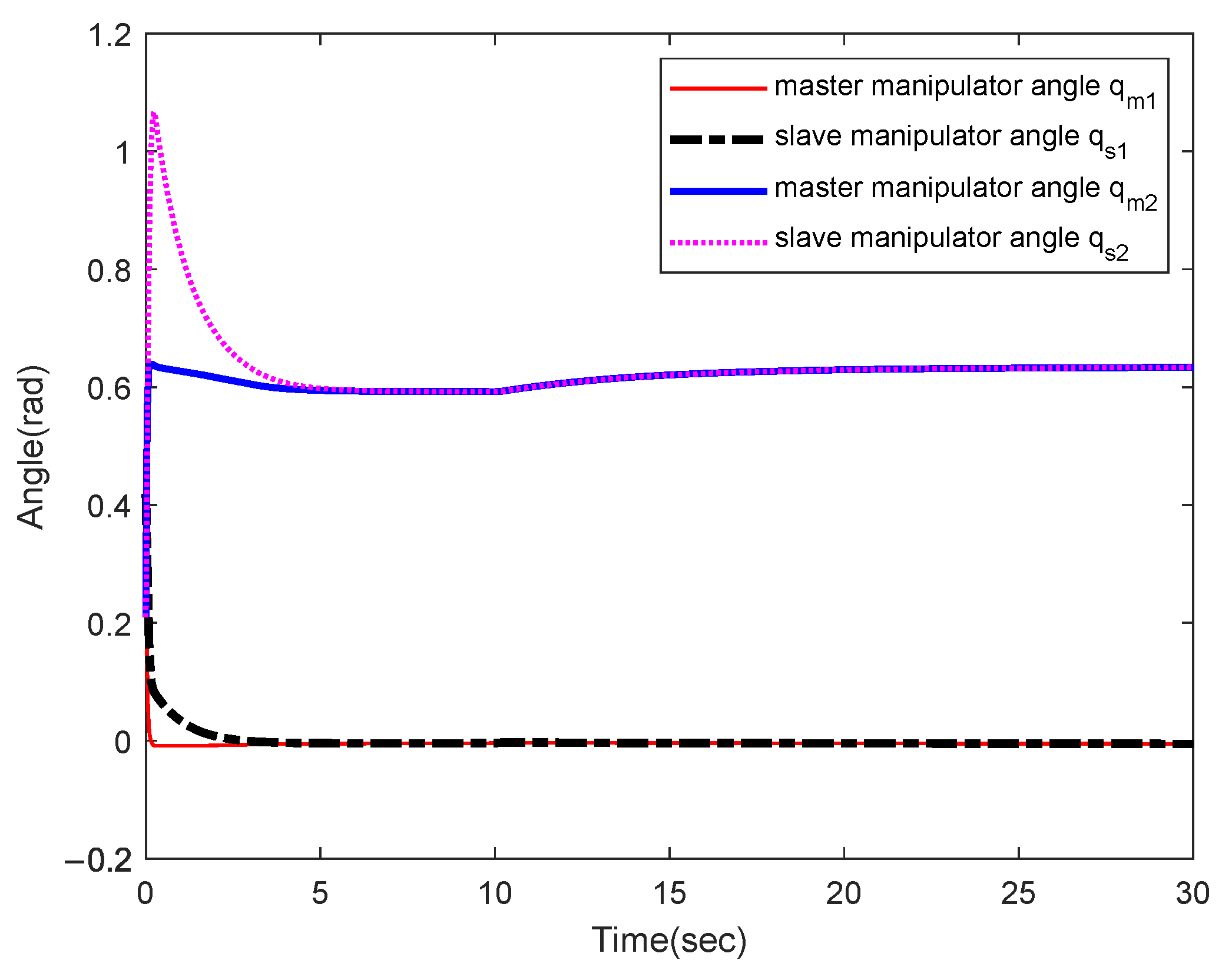
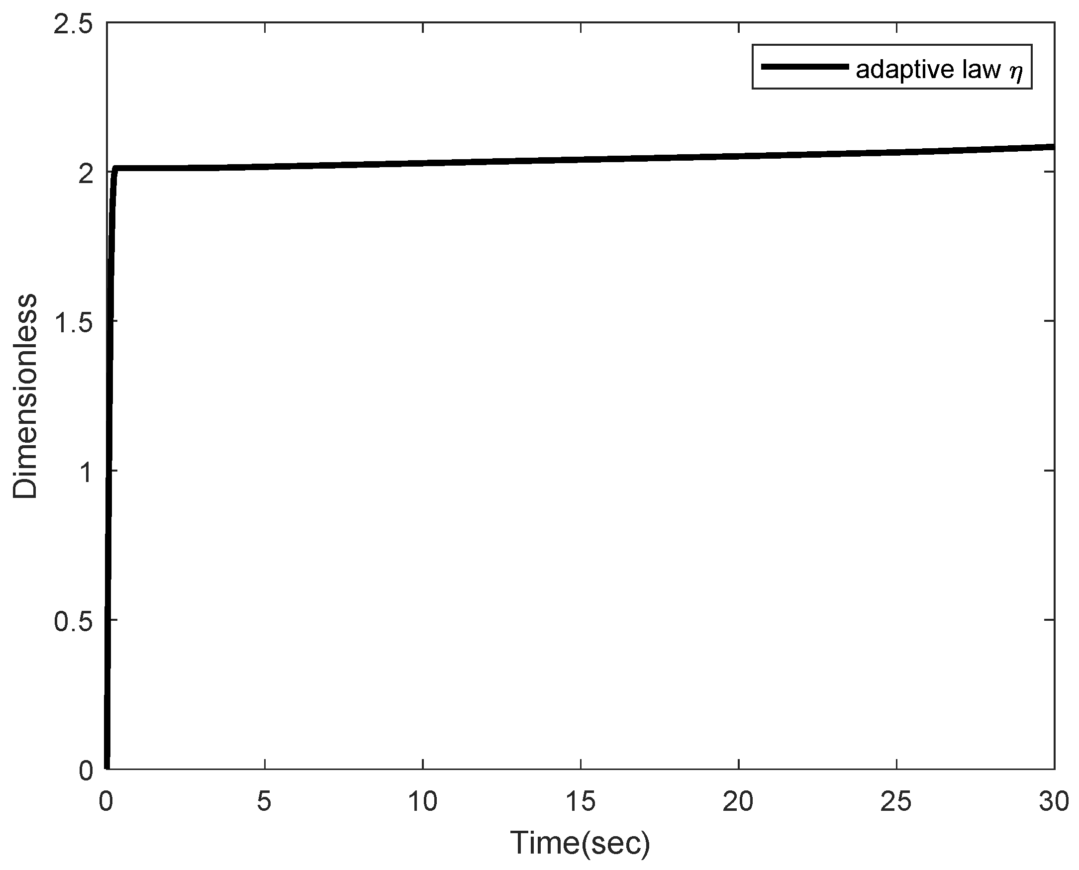
From Figure 4, Figure 5 and Figure 6, it can be observed that the static tracking error of the slave manipulator’s position with respect to the master manipulator’s position is , with no overshoot in overall tracking. After the force is released on the master manipulator, both the slave and master manipulators eventually come to a stop at a distance of 0.1m from the critical contact point with the environment. The slave manipulator still ensures position tracking of the master manipulator, while the master manipulator achieves force tracking of the slave manipulator. As shown in Figure 7 and Figure 8, the output parameters of the adaptive law for the master and slave manipulators are bounded, ensuring the effectiveness of the estimation values and achieving system control stability.
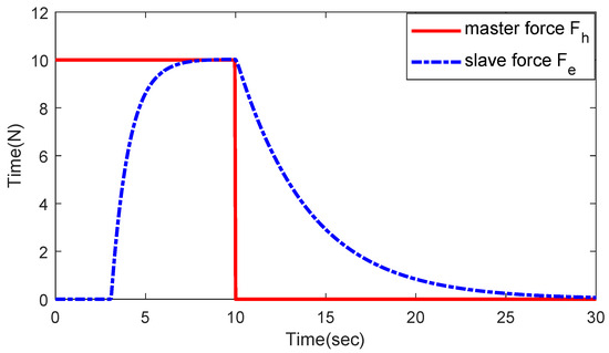
Figure 4.
The force tracking curves of master and slave manipulators.
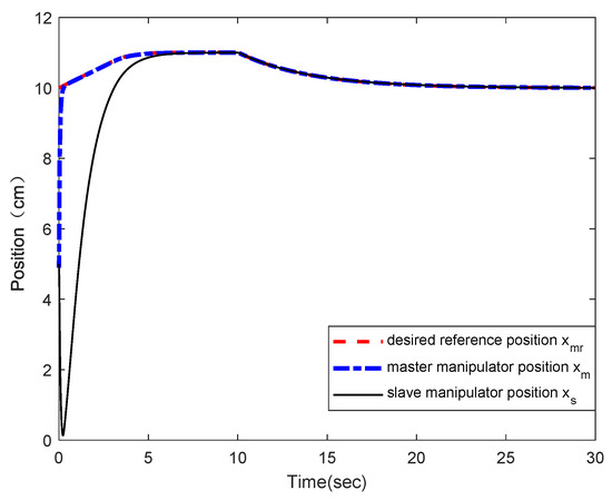
Figure 5.
The position tracking curves of master and slave manipulators.

Figure 6.
The angle tracking curves of master and slave manipulators.
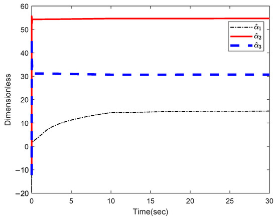
Figure 7.
The curves of master adaptive law.
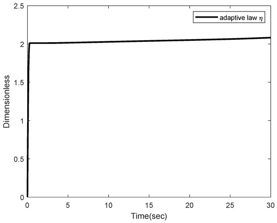
Figure 8.
The curves of slave adaptive law.
From Figure 4, Figure 5, Figure 6 and Figure 7, it can be observed that, under the system uncertain models and external disturbance conditions, the overall system still ensures force and position tracking of the slave manipulator with respect to the master manipulator. The adaptive control of the master manipulator and the radial basis function (RBF) network of the slave manipulator compensate for external disturbances and model uncertainties.
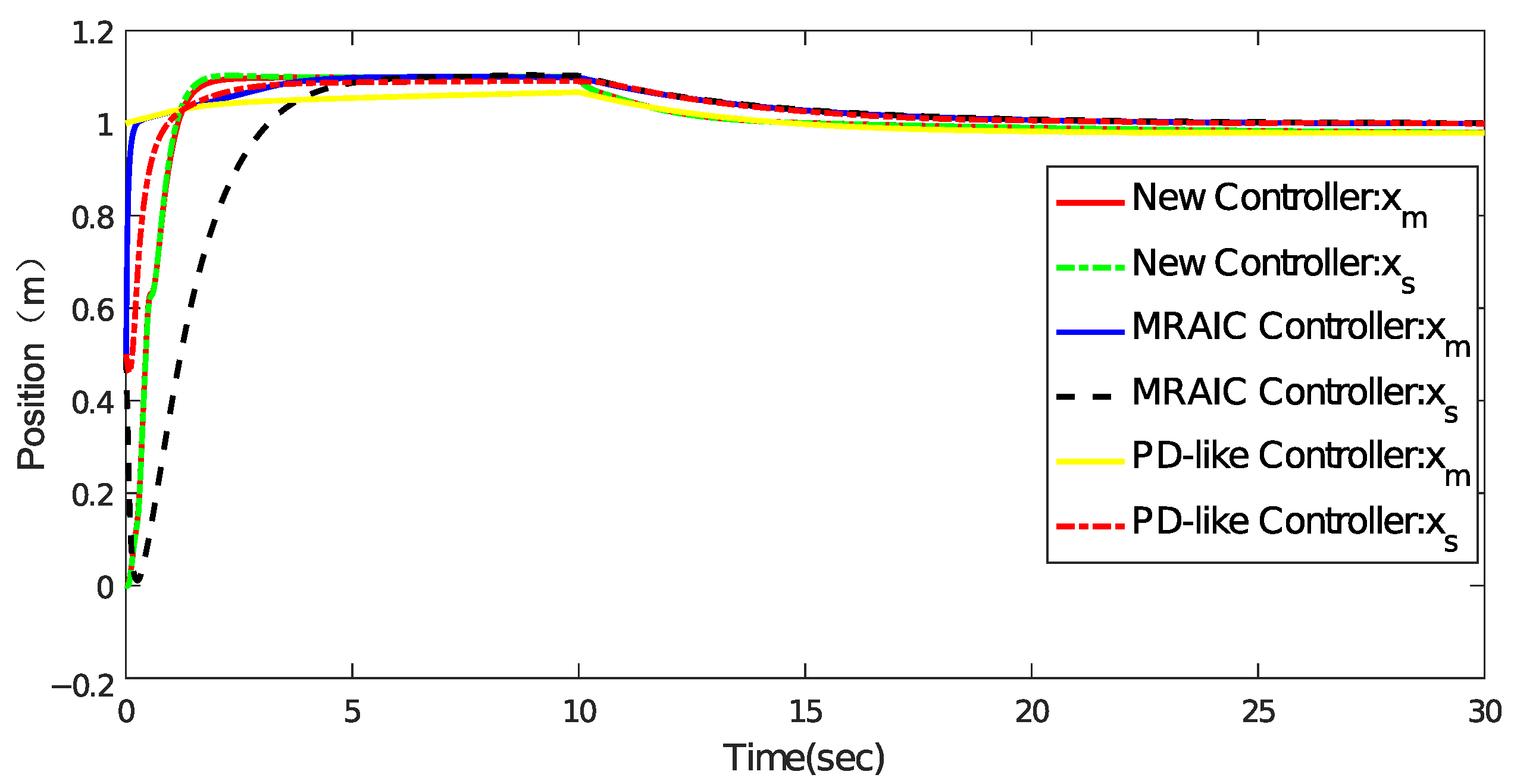
To verify the effectiveness and reliability of the newly designed approach, a comparison is made with the PD+like scheme, as proposed in reference [43], and the model reference adaptive impedance control (MRAIC), as illustrated in reference [44]. The manipulator dynamics are described by Equation (1), and the two-link degree-of-freedom (DOF) serial teleoperation system shown in Figure 1 is subjected to joint friction and external disturbances. A 10 N force is applied in the x-axis direction on the master manipulator, and the force and position responses of the three controllers are recorded and depicted in Figure 9 and Figure 10.
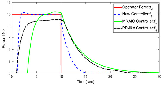
Figure 9.
The curves of master and slave forces in different controllers.
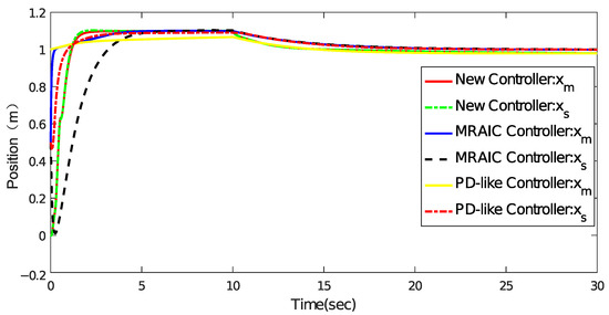
Figure 10.
The curves of master and slave positions in different controllers.
From Figure 9 and Figure 10, we can conclude that the proposed adaptive control strategy exhibits superior force–position tracking convergence performance compared with the other two controllers, especially in the presence of system uncertainty and external disturbances. The response of the designed approach has the characteristics of little overshoot and no static errors, and the response shaking is suppressed with the new controller under external disturbances.
7. Experimental Verification
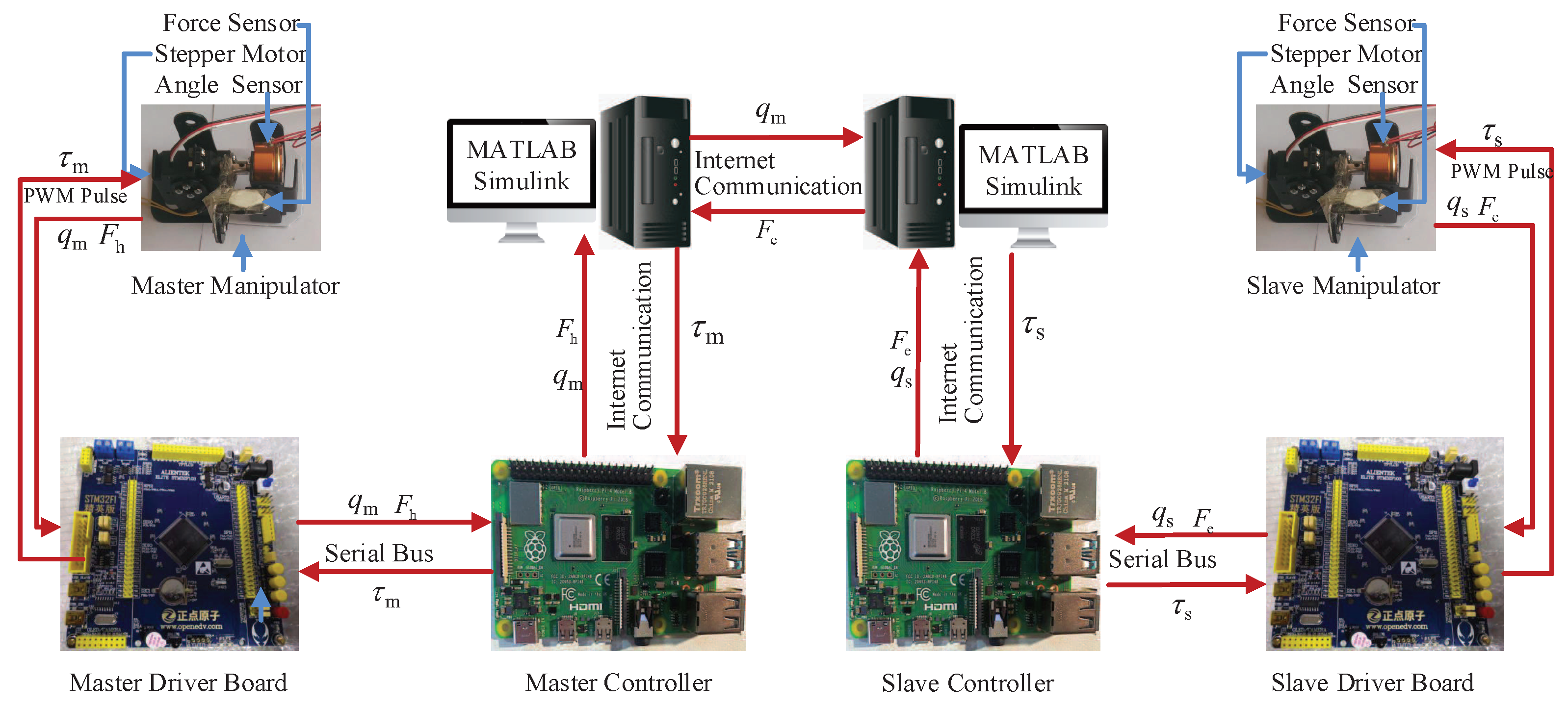
According to the simulation verification above, effective performance in force and position tracking ability is demonstrated with the proposed approach. For further research and verification, a single-degree-of-freedom (DOF) manipulator teleoperation experimental system is set up with the proposed controller. Similar to the simulation system, the complete structural diagram with the proposed controller is depicted in Figure 11.
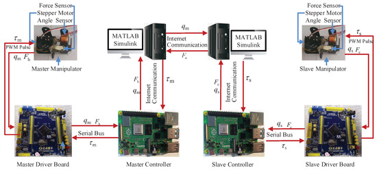
Figure 11.
The experiment setup of single joint teleoperation system.
Both the master and slave manipulators are designed with the same structure, comprising a single-degree-of-freedom (DOF) manipulator driven by a stepper motor to achieve drive torque output. An angle sensor is coaxially connected with the linkage to measure the rotation joint position. Additionally, a piezoelectric film-type tactile force sensor is installed at the force sensing point of the linkage end to measure the force exerted by the master operator.
The master driver board is responsible for acquiring the angle and tactile force signals through A/D conversion. It also receives the control law for the master manipulator from the master controller through the serial bus, and sends the collected force and position information of the master manipulator back to the master controller through the same serial bus. The master controller is connected to the master host computer via the internet, transmitting the master force and position signals to the master computer. It also receives the control law from the master host computer, which is then converted into a PWM pulse performance and sent to the master driver board for execution. The master host computer primarily runs the Matlab/Simulink platform, supporting Peter Corke’s robot toolbox [45] and the hardware board structure. The hardware support is realized by installing the driver package in the Matlab environment. The Matlab/Simulink platform obtains the master position and force information from the master controller, simultaneously obtaining the slave position and force information from the slave host computer through internet communication. The robot toolbox and the single DOF manipulator model are used to calculate the adaptive impedance control law, and the resulting control law is sent to the master controller.
Simultaneously, the Matlab/Simulink platform running on the master computer transmits the master position and force information to the slave host computer via internet communication. Similarly, the slave host computer runs mainly on the Matlab/Simulink platform. It receives the slave position and force information through internet communication from the slave controller. By combining this information with the master position and force information, the slave adaptive law is calculated and transmitted back to the slave controller. At the same time, the slave position and force information are also transmitted to the master host computer.
The slave controller obtains the control law from the slave host computer, converts it into a PWM pulse performance, and sends it to the slave driver board. At the same time, the slave controller obtains the slave force and position information from the driver board and transmits it to the slave host computer. The slave driver board is responsible for collecting the force and position signals through A/D conversion. It also controls the slave stepper motor using PWM pulse signals. The Matlab/Simulink platform supports the robot toolbox and hardware boards such as the Raspberry Pi. If the Raspberry Pi 4B, which is equivalent to a microcomputer, is chosen as the controller of the master and slave manipulators, it supports network communication and serial communication.
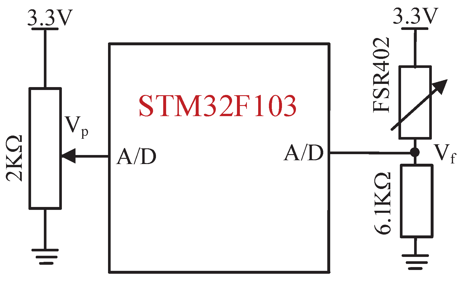
The A/D conversion process is used to obtain force and position signals, as shown in Figure 12. We express the force unit in mV instead of N, as the true force value is not required for this experiment. It is important to emphasize that the accuracy and precision of the A/D conversion process are critical to the success of this experiment. Any errors or noise in the A/D conversion process can have a significant impact on the quality of the acquired signals. Therefore, it is imperative to ensure that the A/D converter is correctly calibrated and that the input signal is within the valid input range.
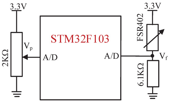
Figure 12.
The measurement principle of the force and position signals.
In conclusion, this experiment highlights the use of A/D conversion for force and position signal acquisition using a tactile force sensor and a precision conductive potentiometer. The accuracy and precision of the A/D conversion process are crucial factors for the experiment’s success, and care must be taken to calibrate the A/D converter correctly and ensure a valid input signal.
In order to display the effect of the experiment better, by sensing the stiffness of the operation object directly and avoiding blocking the stepper motor of the slave manipulator with an insufficient force contacting the force sensor, the virtual force, , is formulated instead of the real slave operation force measurement. The slave feedback force is considered as the linear function of the slave rotation joint position, which is expressed as Equation (32). The operation object is seen as a spring, and the greater the rotation angle is, the greater is the feedback force. The initial rotation position is , and is the virtual spring coefficient. As a result, the soft or hard degree can be acquired by the operator with a different .
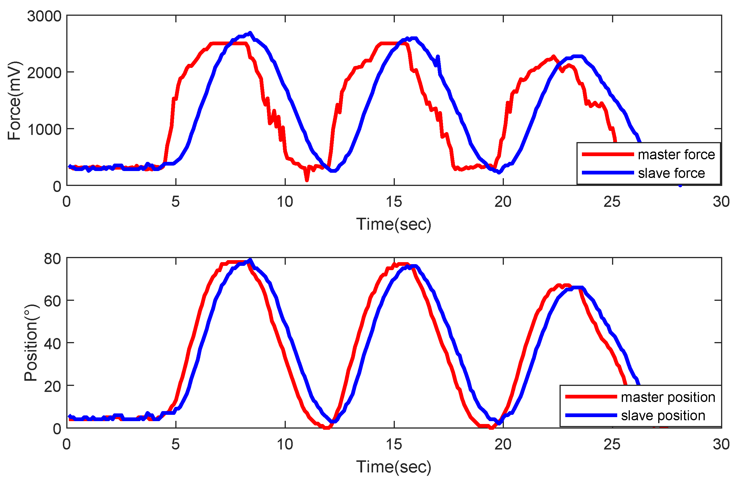
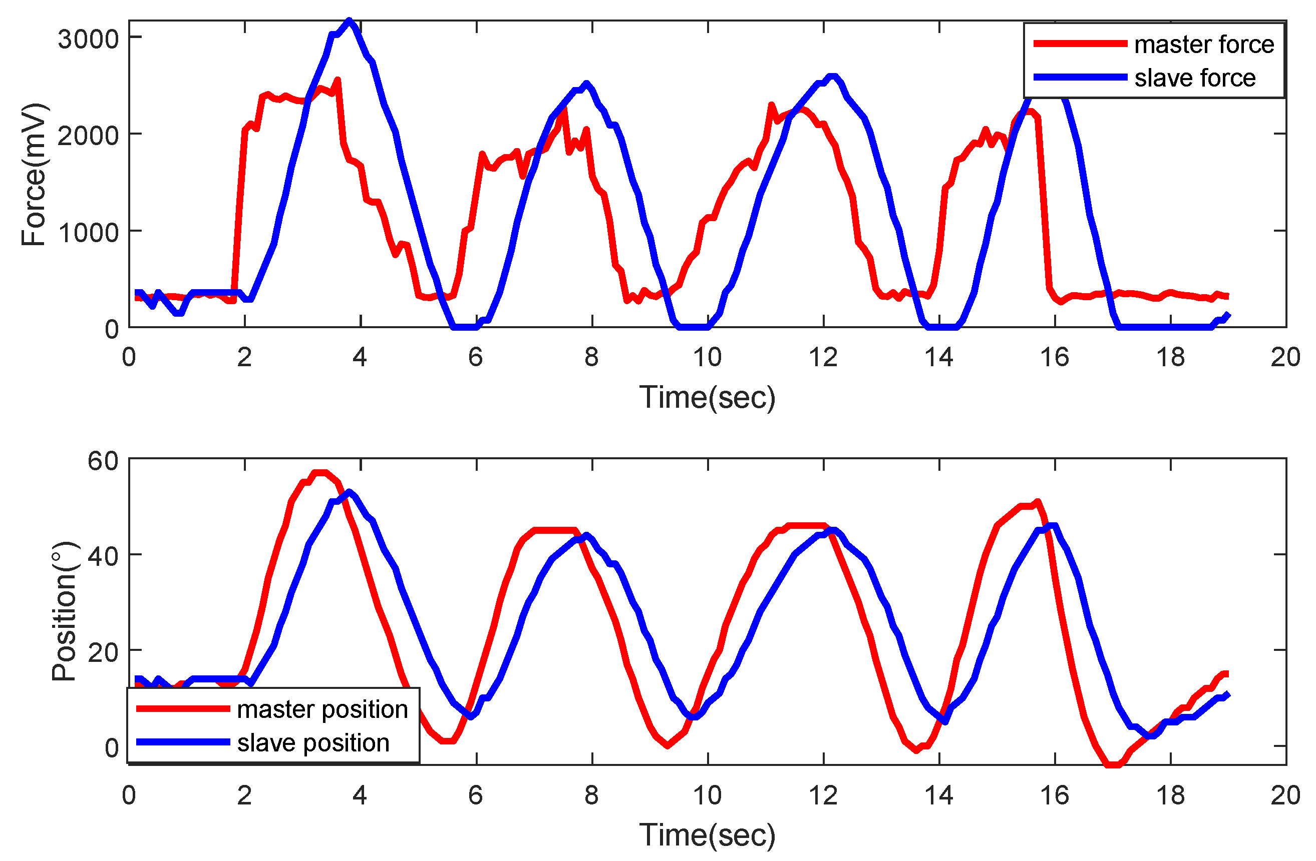
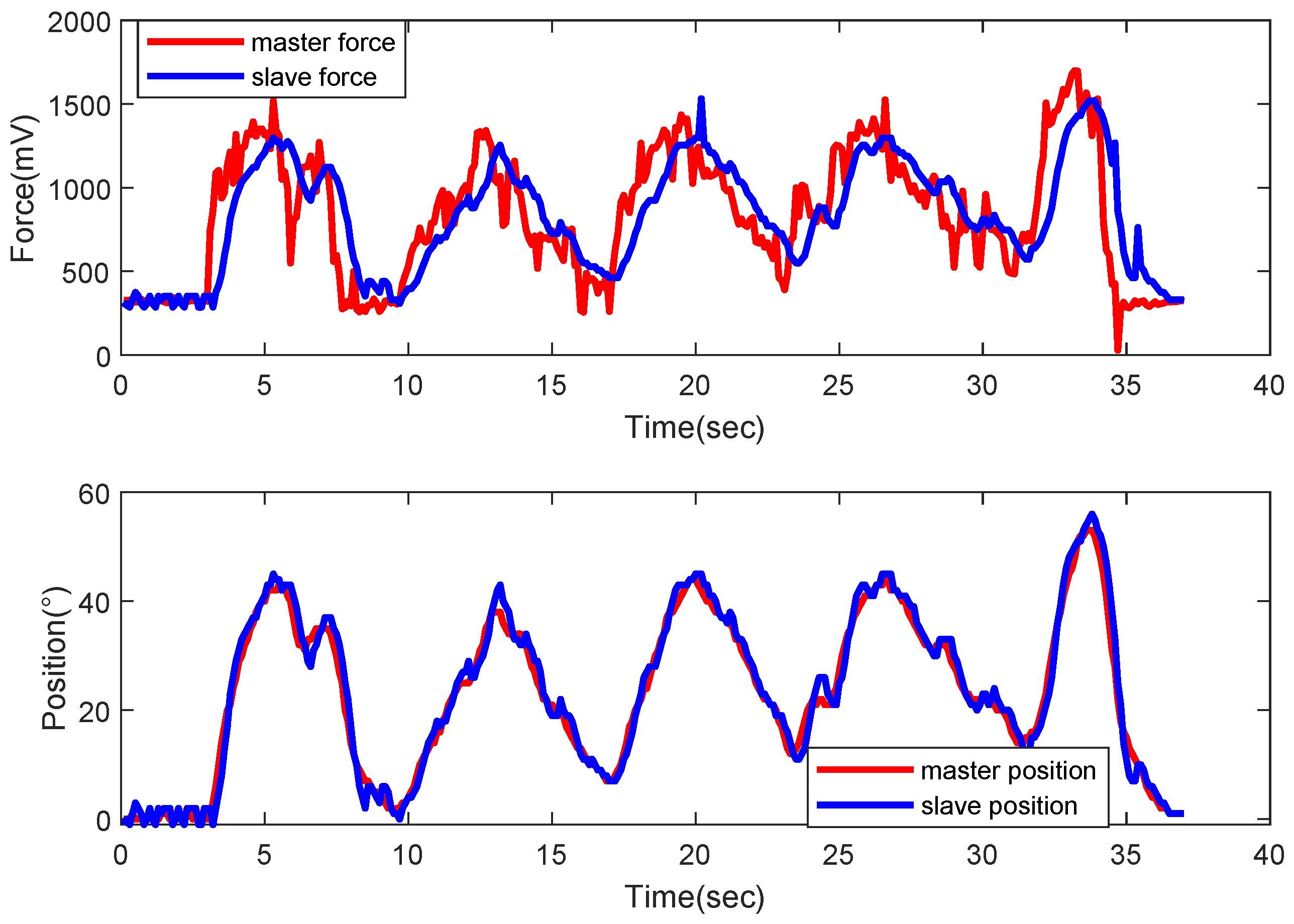
The uncertainty disturbance is added to the dynamic model in the linkage in the Matlab/Simulink environment. The direction of the master and slave force, denoted as and , changes from time to time with the different rotation angle, and, as a result, and in the master desired impedance model, Equation (10), can, respectively, be described as and in the MATLAB/Simulink platform. The experimental process consists of exerting the force on the master force sensor on the master end-linkage, releasing the force and applying the force with several cycles, recording the force and position data, and plotting the diagram demonstrated in Figure 13, Figure 14 and Figure 15. What is more, the virtual spring elasticity coefficient is set as , 52, and 61 mV, respectively.
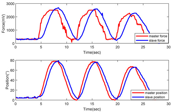
Figure 13.
The force and position tracking curves ( mV).
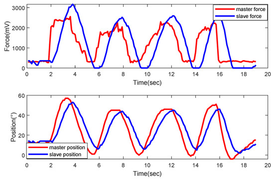
Figure 14.
The force and position tracking curves ( mV).
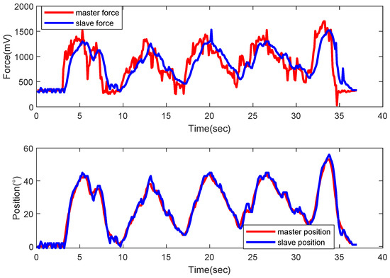
Figure 15.
The force and position tracking curves ( mV).
According to Figure 13, Figure 14 and Figure 15, it can be concluded that the force and position asymptotic convergence of the dual manipulators is achieved with the controller under the periodically applied and released force on the master manipulator. The response characteristics of the master force tracking and slave position tracking are fast, following the response and small overshoot. The controller ensures that the operator applying force on the master manipulator can immediately sense the slave’s operation force. After the master force is released, the dual manipulators still guarantee force and position coordinated synchronization, and, finally, the dual manipulators stay at the critical position with the operation object.
It is evident from Figure 13, Figure 14 and Figure 15 that, even with an uncertain system model and external disturbances, the overall system maintains the force tracking of the master to the slave manipulator and the position tracking of the slave to the master manipulator. This achievement is attributed to the implementation of the model uncertainty adaptive law and the adaptive law for estimating the upper bound of external disturbances, which effectively compensates for both external disturbances and model uncertainties, thus ensuring the robust stability characteristics of the system. The designed control law for the master–slave robotic manipulators ensures consistent synchronous performance in the teleoperation system, and guarantees the system stability and robustness.
According to Figure 13, Figure 14 and Figure 15, the rotation angle range is when mV, comparatively, the rotation angle range is when mV with the same maximum tactile force of 2500 mV on the master manipulator. The larger the stiffness coefficient is, the smaller the rotation angle range is, which means the operator can sense the stiffness of the slave operation object with the same master force applying. As a result, the whole experiment verifies the effectiveness of the proposed controller, which satisfies the force–position coordinated synchronization of the dual manipulators and the immersion sensing for the slave environment.
8. Conclusions
In the teleoperation process under uncertain conditions caused by the mathematical models of the master and slave manipulators and external disturbances, an adaptive bilateral control strategy is proposed. To compensate for uncertainties and nonlinear characteristics induced by friction disturbances and external uncertainties in the master manipulator, a reference adaptive impedance control based on the nominal model is designed. The adaptive control law is used to compensate for uncertainties by adjusting the desired trajectory based on the force error between the sensed force and the force applied by the operator, achieving force tracking of the slave manipulator.
The uncertainties in the slave manipulator are compensated using an RBF network, and the tracking error is eliminated using a sliding mode variable structure controller and an adaptive controller, ensuring position tracking of the slave manipulator with respect to the master manipulator and improving the tracking performance. The asymptotic convergence performance and global stability of the tracking are proven with a Lyapunov function, guaranteeing the coordinated and consistent force–position tracking capability in the teleoperation process. The results demonstrate that the overall control system has good force–position tracking capability under internal and external disturbances, and the overall system exhibits stability and adaptability.
Author Contributions
J.Z. and M.X. designed the controller; M.X. and S.L. performed the experiments; J.Z. and Z.L. analyzed the data; J.Y. contributed reagents/materials/analysis tools; J.Z. wrote the paper. All authors have read and agreed to the published version of the manuscript.
Funding
This work was supported by Key Scientific Research Projects of University in Henan Province (No. 24B413003), The Basic Research Business Fund Special Project of Henan Polytechnic University (No. NSFRF230434), Natural Science Foundation of Henan (No. 232300421152), and Henan Province Scientific and Technological Project of China (Nos. 232102240036, 232102220030, 232102240103 and 232102211004).
Data Availability Statement
Data are contained within the article.
Conflicts of Interest
The authors declare no conflicts of interest.
References
- Valeev, A. Performance Evaluation of Subsea Petroleum Activities Utilizing Vessels. Master’s Thesis, University of Stavanger, Stavanger, Norway, 2018. [Google Scholar]
- Santos, H.; Perondi, E.; Wentz, A.; Silva, A.; Barone, D.; Basso, E.; Reis, N.; Galassi, M.; Pinto, H.; Castro, B.; et al. A Robot for Removing Hydrate and Paraffin Plugs in Offshore Flexible Lines–Development and Experimental Trials. In Proceedings of the SPE Annual Technical Conference and Exhibition? Baku, Azerbaijan, 6–18 October 2019; SPE: Kuala Lumpur, Malaysia, 2019; p. D011S009R001. [Google Scholar]
- Ivanega, D.; Szczepanek, M. Assessing damage and predicting future risks: A study of the Schilling Titan 4 manipulator on work class ROVs in offshore oil and gas industry. Ocean. Eng. 2024, 291, 116282. [Google Scholar] [CrossRef]
- Song, C. Doppler Velocity Log for Navigation System in Underwater Vehicle. In Encyclopedia of Ocean Engineering; Springer: Berlin/Heidelberg, Germany, 2022; pp. 375–381. [Google Scholar]
- Sivčev, S.; Coleman, J.; Omerdić, E.; Dooly, G.; Toal, D. Underwater manipulators: A review. Ocean. Eng. 2018, 163, 431–450. [Google Scholar] [CrossRef]
- Wang, T.; Li, Y.; Zhang, J.; Zhang, Y. A novel bilateral impedance controls for underwater tele-operation systems. Appl. Soft Comput. 2020, 91, 106194. [Google Scholar] [CrossRef]
- Wang, T.; Gao, J.; Xie, O. Sliding mode disturbance observer and Q learning-based bilateral control for underwater teleoperation systems. Appl. Soft Comput. 2022, 130, 109684. [Google Scholar] [CrossRef]
- Huang, F.; Chen, X.; Chen, Z.; Pan, Y.J. A novel SMMS teleoperation control framework for multiple mobile agents with obstacles avoidance by leader selection. IEEE Trans. Syst. Man Cybern. Syst. 2022, 53, 1517–1529. [Google Scholar] [CrossRef]
- Mehrjouyan, A.; Menhaj, M.B.; Hooshiar, A. Safety-enhanced observer-based adaptive fuzzy synchronization control framework for teleoperation systems. Eur. J. Control 2023, 73, 100885. [Google Scholar] [CrossRef]
- Yang, X.; Yan, J.; Hua, C.; Guan, X. Position Measurement Based Slave Torque Feedback Control for Teleoperation Systems With Time-Varying Communication Delays. IEEE/CAA J. Autom. Sin. 2022, 10, 388–402. [Google Scholar] [CrossRef]
- Li, H.; Chou, W. Adaptive FNN Backstepping Control for Nonlinear Bilateral Teleoperation With Asymmetric Time Delays and Uncertainties. Int. J. Control Autom. Syst. 2023, 21, 3091–3104. [Google Scholar] [CrossRef]
- Bouteraa, Y.; Alattas, K.A.; Peng, T.; Fekih, A.; Rahmani, R.; Mobayen, S. Design of robust adaptive fuzzy control for uncertain bilateral teleoperation systems based on backstepping approach. IET Control Theory Appl. 2023, 17, 800–813. [Google Scholar] [CrossRef]
- Saini, S.; Orlando, M.F.; Pathak, P.M. Adaptive control of a master-slave based robotic surgical system with haptic feedback. IEEE Trans. Autom. Sci. Eng. 2022, 20, 1125–1138. [Google Scholar] [CrossRef]
- Yang, Y.; Gan, L.; Chen, Y.; Hua, C. Adaptive neural network control for flexible telerobotic systems with communication constraints. J. Frankl. Inst. 2022, 359, 4751–4775. [Google Scholar] [CrossRef]
- Song, C.; Lau, D. Workspace-based model predictive control for cable-driven robots. IEEE Trans. Robot. 2022, 38, 2577–2596. [Google Scholar] [CrossRef]
- Zhang, J.J.; Fang, Z.L.; Zhang, Z.Q.; Gao, R.Z.; Zhang, S.B. Trajectory tracking control of nonholonomic wheeled mobile robots using model predictive control subjected to lyapunov-based input constraints. Int. J. Control Autom. Syst. 2022, 20, 1640–1651. [Google Scholar] [CrossRef]
- Moreno-Luna, R.; Martin-Jimenez, D.I.; Callejon-Leblic, M.; Gonzalez-Garcia, J.; Maza-Solano, J.M.; Porras-Gonzalez, C.; Sanchez-Gomez, S. Usefulness of bilateral mucoplasty plus reboot surgery in severe type-2 chronic rhinosinusitis with nasal polyps. Rhinology 2022, 60, 368–376. [Google Scholar] [CrossRef] [PubMed]
- Nahri, S.N.F.; Du, S.; Van Wyk, B.J. A review on haptic bilateral teleoperation systems. J. Intell. Robot. Syst. 2022, 104, 1–23. [Google Scholar] [CrossRef]
- Li, R.; Zhang, J.; Zhao, X. Dynamic wind farm wake modeling based on a Bilateral Convolutional Neural Network and high-fidelity LES data. Energy 2022, 258, 124845. [Google Scholar] [CrossRef]
- Xiao, W.; Chen, K.; Fan, J.; Hou, Y.; Kong, W.; Dan, G. AI-driven rehabilitation and assistive robotic system with intelligent PID controller based on RBF neural networks. Neural Comput. Appl. 2023, 35, 16021–16035. [Google Scholar] [CrossRef]
- Qin, H.; Yang, H.; Sun, Y.; Feng, L. Fixed-time stable bilateral teleoperation of underwater manipulator using prescribed performance terminal sliding surfaces. J. Ournal. Frankl. Inst. 2023, 360, 3280–3306. [Google Scholar] [CrossRef]
- Yang, Y.; Yan, Y.; Hua, C.; Li, J.; Pang, K. Prescribed Performance Control for Teleoperation System of Nonholonomic Constrained Mobile Manipulator Without Any Approximation Function. IEEE Trans. Autom. Sci. Eng. 2023. [Google Scholar] [CrossRef]
- Yuan, Y.; Wang, Y.; Guo, L. Force reflecting control for bilateral teleoperation system under time-varying delays. IEEE Trans. Ind. Inform. 2018, 15, 1162–1172. [Google Scholar] [CrossRef]
- Chen, Z.; Huang, F.; Sun, W.; Gu, J.; Yao, B. RBF-neural-network-based adaptive robust control for nonlinear bilateral teleoperation manipulators with uncertainty and time delay. IEEE/ASME Trans. Mechatronics 2019, 25, 906–918. [Google Scholar] [CrossRef]
- Sharifi, M.; Behzadipour, S.; Salarieh, H.; Tavakoli, M. Assist-as-needed policy for movement therapy using telerobotics-mediated therapist supervision. Control Eng. Pract. 2020, 101, 104481. [Google Scholar] [CrossRef]
- Yang, Y.; Hua, C.; Li, J.; Guan, X. Finite-time output-feedback synchronization control for bilateral teleoperation system via neural networks. Inf. Sci. 2017, 406, 216–233. [Google Scholar] [CrossRef]
- Dehghan, S.A.M.; Koofigar, H.R.; Sadeghian, H.; Ekramian, M. Observer-based adaptive force–position control for nonlinear bilateral teleoperation with time delay. Control Eng. Pract. 2021, 107, 104679. [Google Scholar] [CrossRef]
- Aboutalebian, B.; Talebi, H.A.; Etedali, S.; Suratgar, A.A. Adaptive control of teleoperation system based on nonlinear disturbance observer. Eur. J. Control 2020, 53, 109–116. [Google Scholar] [CrossRef]
- Zhang, J.; Wang, F.; Wen, G. Sliding-mode control for teleoperation system with uncertain kinematics and dynamics: An observer-based approach. J. Frankl. Inst. 2023, 360, 8300–8319. [Google Scholar] [CrossRef]
- Li, L.; Liu, Z.; Ma, Z.; Huang, P.; Guo, S. Adaptive neural learning fixed-time control for uncertain teleoperation system with time-delay and time-varying output constraints. Int. J. Robust Nonlinear Control 2022, 32, 8912–8931. [Google Scholar] [CrossRef]
- Kebria, P.M.; Khosravi, A.; Nahavandi, S.; Wu, D.; Bello, F. Adaptive type-2 fuzzy neural-network control for teleoperation systems with delay and uncertainties. IEEE Trans. Fuzzy Syst. 2019, 28, 2543–2554. [Google Scholar] [CrossRef]
- Yang, Y.; Yang, Y.; Li, X.; Hua, C. Adaptive synchronization control of multimanipulator teleoperation system under constrained discrete-time network communication. Int. J. Robust Nonlinear Control 2023, 33, 1807–1820. [Google Scholar] [CrossRef]
- Yang, H.; Liu, L.; Wang, Y. Observer-based sliding mode control for bilateral teleoperation with time-varying delays. Control Eng. Pract. 2019, 91, 104097. [Google Scholar] [CrossRef]
- Kim, B.Y.; Ahn, H.S. A design of bilateral teleoperation systems using composite adaptive controller. Control Eng. Pract. 2013, 21, 1641–1652. [Google Scholar] [CrossRef]
- Sharifi, M.; Behzadipour, S.; Vossoughi, G. Nonlinear model reference adaptive impedance control for human–robot interactions. Control Eng. Pract. 2014, 32, 9–27. [Google Scholar] [CrossRef]
- Al-Shuka, H.F.; Leonhardt, S.; Zhu, W.H.; Song, R.; Ding, C.; Li, Y. Active impedance control of bioinspired motion robotic manipulators: An overview. Appl. Bionics Biomech. 2018, 2018, 8203054. [Google Scholar] [CrossRef]
- Mendoza, M.; Bonilla, I.; González-Galván, E.; Reyes, F. Impedance control in a wave-based teleoperator for rehabilitation motor therapies assisted by robots. Comput. Methods Programs Biomed. 2016, 123, 54–67. [Google Scholar] [CrossRef] [PubMed]
- Sharifi, M.; Behzadipour, S.; Vossoughi, G. Model reference adaptive impedance control of rehabilitation robots in operational space. In Proceedings of the 2012 4th IEEE RAS & EMBS International Conference on Biomedical Robotics and Biomechatronics (BioRob), Rome, Italy, 24–27 June 2012; IEEE: New York City, NY, USA, 2012; pp. 1698–1703. [Google Scholar]
- Hsu, C.F.; Lin, C.M.; Yeh, R.G. Supervisory adaptive dynamic RBF-based neural-fuzzy control system design for unknown nonlinear systems. Appl. Soft Comput. 2013, 13, 1620–1626. [Google Scholar] [CrossRef]
- Ganjefar, S.; Rezaei, S.; Hashemzadeh, F. Position and force tracking in nonlinear teleoperation systems with sandwich linearity in actuators and time-varying delay. Mech. Syst. Signal Process. 2017, 86, 308–324. [Google Scholar] [CrossRef]
- Londhe, P.; Mohan, S.; Patre, B.; Waghmare, L. Robust task-space control of an autonomous underwater vehicle-manipulator system by PID-like fuzzy control scheme with disturbance estimator. Ocean. Eng. 2017, 139, 1–13. [Google Scholar] [CrossRef]
- Zhang, W.; Qi, N.; Yin, H. Neural-network tracking control of space robot based on sliding-mode variable structure. Control Theory Appl. 2011, 28, 1141–1144. [Google Scholar]
- Slawinski, E.; García, S.; Salinas, L.; Mut, V. PD-like controller with impedance for delayed bilateral teleoperation of mobile robots. Robotica 2016, 34, 2151–2161. [Google Scholar] [CrossRef]
- Lv, X.; Han, J.; Yang, C.; Cong, D. Model reference adaptive impedance control in lower limbs rehabilitation robot. In Proceedings of the 2017 IEEE International Conference on Information and Automation (ICIA), Macau, China, 18–20 July 2017; IEEE: New York City, NY, USA, 2017; pp. 254–259. [Google Scholar]
- Corke, P.; Haviland, J. Not your grandmother’s toolbox–the robotics toolbox reinvented for python. In Proceedings of the 2021 IEEE International Conference on Robotics and Automation (ICRA), Xi’an, China, 30 May–5 June 2021; IEEE: New York City, NY, USA, 2021; pp. 11357–11363. [Google Scholar]


Disclaimer/Publisher’s Note: The statements, opinions and data contained in all publications are solely those of the individual author(s) and contributor(s) and not of MDPI and/or the editor(s). MDPI and/or the editor(s) disclaim responsibility for any injury to people or property resulting from any ideas, methods, instructions or products referred to in the content. |
© 2024 by the authors. Licensee MDPI, Basel, Switzerland. This article is an open access article distributed under the terms and conditions of the Creative Commons Attribution (CC BY) license (https://creativecommons.org/licenses/by/4.0/).