Abstract
As the capacity of the electrical system increases, so does the capacity of the electromagnetic contactor (MC). This increases the burden on the MC drive, which consumes unnecessary power in the system. MC is characterized by different initial starting-operating currents and holding currents to maintain contact. However, the operating voltage is constant regardless of the operating state. The initial starting current is considerably larger than that required to maintain contact. However, once the electromagnetic contactor is in the closed state, the current to maintain the contact is relatively small compared to the initial starting operating currents. Therefore, this study proposes two types of two-level excitation-current type MC drives that can reduce the drive power by employing features that have different conditions depending on the operating state of the MC. The overall drive power is reduced by applying different excitation currents based on the operating state. The controller and system proposed in this study were simulated using Powersim 9.1 (PSIM), and the feasibility was verified by manufacturing an analog-type driver using LM2576 and a digital-type driver using an MCU. The simulation and experimental results provide significant data for verifying the high performance and reliability of the proposed controller and system.
1. Introduction
Recently, the importance of direct current (DC)-type electromagnetic contactors (MCs) has increased owing to the activation of renewable power sources, microgrids, electric vehicles, and the like [1,2,3]. In the future, when the full DC power demand is achieved, many MCs are expected to be driven by DC power owing to the lack of sufficient alternating current (AC) power [4,5]. Moreover, in the existing AC networks, the use of DC-type MC is increasing to prevent the malfunction of the surrounding electronic devices owing to arcs generated when the MC is turned off [6,7]. For this reason, studies on the electromagnetic effect occurring in DC excitation-type electronic contactors are also being actively conducted [8,9].
Currently, the rapidly increasing power demands of DC systems, including electric vehicles, require larger capacity power converters and the capacity of MC is increasing proportionally [10,11,12]. When the capacity of the MC increases, the required power also increases, thereby increasing the burden on the power supply. The operation of an MC can be divided into an initial operating state that changes from an open to closed and a contact maintenance state that maintains the contact [13]. The initial operation of an MC occurs when current is applied to the excitation coil configured inside the MC, the contacts are attached by force, and an electric circuit is connected [14]. When the contact point is maintained, the exciting current is continuously applied; when the supply of the exciting current is stopped, the electromagnet loses its force, and the contact point is opened by a spring mounted inside, separating the electric circuit [15,16]. Here, the contact point means that the movable contacts and station contacts shown in Figure 1 make contact when an excitation current is applied. The initial starting operating current of the MC is significantly larger than the holding current required to maintain the contact point, and the voltage applied to the MC is often the same. At this point, the holding current required increases as the capacity of the MC increases [17,18]. Due to the characteristics of the MC, the holding current application time for which the contact is maintained is considerably higher; therefore, reducing the power in the holding state is significantly helpful in saving the system energy [19,20,21]. This study proposes a two-level exciting current-type electromagnetic contactor driver that can reduce the driving power using the characteristics of different conditions depending on the driving state of the electromagnetic contactor. The two-level excitation current can be divided into a starting current that can close the MC when it is open and a minimum current that can maintain the contact point after it is closed. The proposed two-level electromagnetic contactor driver applies an algorithm that distinguishes the operation modes based on the excitation current ripple slope in the initial starting state and the state in which the contact point is maintained. The controller and system proposed in this study were simulated using Powersim (PSIM), and their feasibility was verified by producing a low-cost prototype using LM2576. Simulation and experimental results were used to obtain meaningful data to verify the high performance and reliability of the proposed method and system.
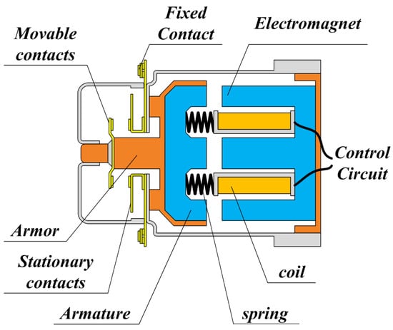
Figure 1.
Structure of electromagnetic contactors.
2. Electromagnetic Contactors Analysis
2.1. Force Characteristics of Electromagnetic Contactors
The MC opens and closes the contact point using the force characteristics of the exciting coil and spring mounted inside.
As shown in Figure 1, when there is no excitation voltage, the contact point is opened using a spring. Power was then supplied to the internal coil to generate force, which closed the contact point [22]. In an MC, the air gap at the time of opening is proportional to the voltage withstand of the MC. To increase the voltage withstand, a magnetic circuit with a large air gap should be constructed. Moreover, when closed, there is almost no air gap in the magnetic circuit and a magnetomotive force that saturates the magnetic flux is applied [23,24].
Figure 2a shows the magnetic circuit of the MC and Figure 2b shows the magnetic equivalent circuit. The reluctance in a magnetic circuit is determined as shown in Equation (1) by the structure of the magnetic circuit and magnetic materials mainly used [25].
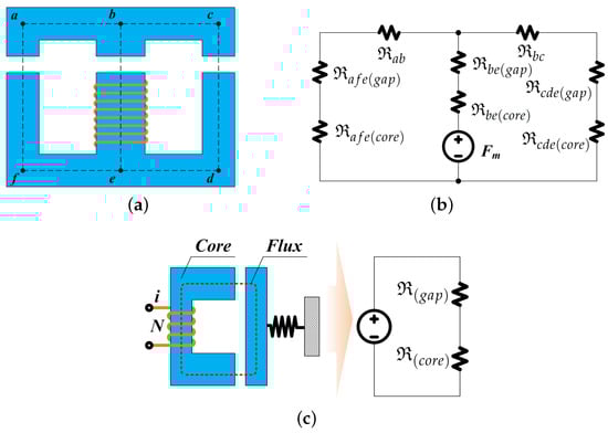
Figure 2.
Magnetic circuit structure and equivalent circuit of the MC. (a) Magnetic circuit of the MC, (b) Magnetic equivalent circuit of the MC, (c) Simple magnetic circuit and an equivalent circuit.
l shown in Equation (1) is the equivalent length of the magnetic circuit, A is the equivalent area of the magnetic circuit, is the permeability of vacuum equal to , is the relative magnetic permeability of the material, is the permeability of the material [26]. Figure 2b shows the symmetric magnetic circuit structure based on magnetomotive force . To simplify the analysis of the magnetic circuit, Figure 2a,b were replaced with a simple magnetic circuit and an equivalent circuit, respectively, as shown in Figure 2c. In the magnetic circuit shown in Figure 2c, is the effective length of the iron core, is the effective length of the air gap is , and the magnetomotive force is given by Equation (2).
At this time, it is assumed that the fringing effect that increases the cross-sectional area of the air gap is ignored. This is because the air gap is very small when the MC is closed state. If the fringing effect is ignored, the cross-sectional areas of the iron core and air gap are the same. From Equation (2), the magnetic flux density of the air gap is defined as Equation (3).
In a simplified equivalent circuit, as shown in Figure 2c, if the magnetic resistance of the iron core is ignored, almost all the magnetic field energy is stored in the air gap, and the magnetic flux density of the air gap is as follows:
The force of the target system can be expressed as follows because the differential value of the displacement of magnetically stored energy is force. Therefore, the equation for force is as follows:
The resistance of the coil can be designed such that the force expressed in Equation (5) is larger than the spring force when the MC is closed. Therefore, when there is no change in the air gap, such as when opened or closed, the back electromotive force of the coil becomes zero, and the current is determined only by the resistance, resulting in the same current.
2.2. Characteristics of Magnetic Flux According to the Gap of Electromagnetic Contactors
As shown in Equation (5), the force in an MC is determined by the magnetic flux density and the cross-sectional area of the air gap. The magnetic flux density is determined by the strength of the magnetic field and the magnetic materials; the magnetization curve based on the magnetic materials is shown in Figure 3.
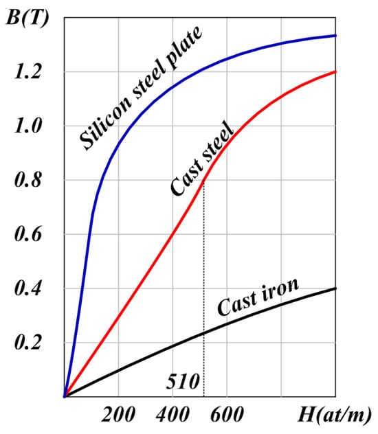
Figure 3.
Magnetization curve of according to magnetic materials.
The magnetic flux density increases almost linearly in areas where the magnetic field strength is small but changes nonlinearly in areas where the magnetic field strength is large; therefore, the magnetization curve, which is the B-H curve, is an important factor in determining the characteristics of the magnetic circuit. Generally, the magnetic materials used in relays are cast steel, and the magnetic flux density was designed to be approximately . The reason for using a magnetic flux density of is the maximum point in the linear region of cast steel shown in Figure 3. Additionally, the magnitude of the force is determined by the cross-sectional area of the magnetic circuit, as shown in Equation (5). The magnetomotive force used to maintain a magnetic flux density of in the magnetic field circuit using the cast steel magnetic materials shown in Figure 3 is as follows:
Additionally, the magnetomotive force required in the air gap is as follows:
Therefore, the total magnetomotive force is defined as follows.
The current to generate the magnetomotive force in Equation (8) is as follows.
As shown in Equation (9), the air gap of the magnetic circuit changes when opening and closing the MC is opened and closed, and the current value required to generate a force above a certain value changes owing to this change in the air gap. In general MC design, the current design of the exciting coil is defined as the value of the design flux density when the MC is opened, that is, when the air gap is at its maximum, as shown in the equation below.
The magnetic flux density regarding the gap in the MC is shown in Figure 4. It was assumed that there was no magnetic saturation when the current value given in Equation (9) was applied to the MC. In the open state with the largest air gap, the designed magnetic flux density was achieved. However, in the closed state with the smallest air gap, the magnetic flux density became significantly large. Accordingly, in an actual MC, magnetic flux saturation occurs in areas where the gap is small. It can be confirmed that this single-current excitation method generates more force than necessary when the MC is closed. Accordingly, when the capacity of the MC is increased, the burden on the driving power supply increases because of the large power loss during operation.
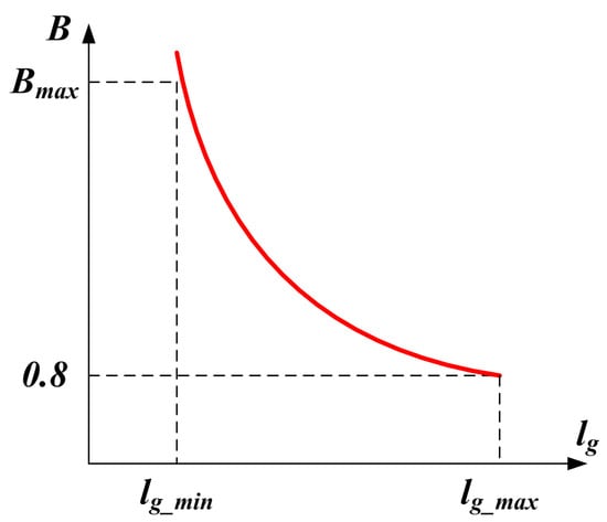
Figure 4.
The magnetic flux density regarding the gap in the contactor.
3. Proposed Two-Level Excitation Current Driver
3.1. Operation Description
The force of an MC is determined by the magnetic flux density, and depending on the gap, the current with the same magnetic flux density has different values, as shown in Equation (10). In Equation (10), the current for maintaining magnetic flux density according to the gap of the MC is shown in Figure 5.
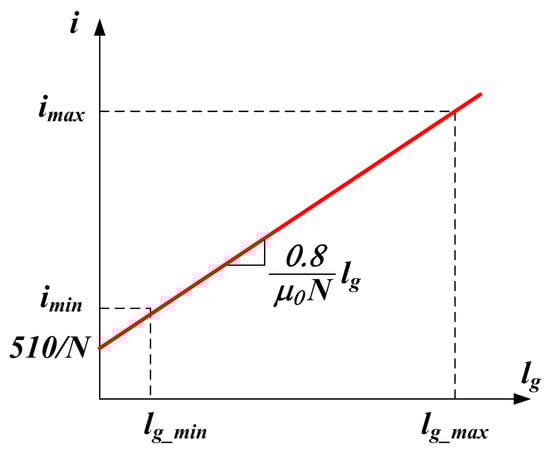
Figure 5.
Current for maintaining magnetic flux density according to the gap.
As shown in Figure 5, the current required to maintain a constant magnetic flux density based on the gap in the magnetic circuit of the MC takes the form of a monotonically increasing linear function. When the MC is open, the gap reaches a maximum, and the current maintaining the same magnetic flux density reaches its maximum value. Conversely, when the MC is in the closed state, the gap is minimized, and the current that maintains the same magnetic flux density is minimized. The time when the gap changes in magnetism is a significantly short period when the closed and open states change, and most operations are in a closed state with a minimum air gap or an open state with a maximum air gap. Therefore, by operating the MC by setting two current levels—the maximum current that maintains the magnetic flux density constant in the open state and the minimum current that maintains the same magnetic flux density in the closed state—the closed state can be maintained with a small excitation current. For a stable closing operation, the excitation coil was initially excited with the maximum current during the MC closing operation. After the MC is completely closed, the excitation coil is excited with the minimum current that can maintain contact. If the MC, which is mostly in a closed state, is operated in the proposed manner, the power share of the power supply to drive the MC is significantly reduced.
Figure 6 shows the basic driving circuit of an MC with a two-level excitation current that operates as a step-down converter. The magnetic circuit of a DC-driven MC has no frequency-dependent hysteresis or eddy current loss. As direct-current-driven MCs are manufactured with a single iron core rather than a stratified iron core, the loss increases significantly if there is a ripple in the excitation current. Therefore, the excitation voltage of a DC-driven MC should be a constant voltage application method without harmonic voltages. The harmonic voltage generated by the switching shown in Figure 6 was removed using an LC filter, which is a passive low-frequency filter to generate a constant voltage. However, for economic reasons, when removing the LC filter and controlling the excitation current of the MC by pulse width modulation (PWM), it is desirable to drive at a low switching frequency to reduce losses caused by the harmonic current. The output voltage according to the duty ratio of the step-down converter switch in Figure 6 is defined as , and various voltages can be produced depending on the duty ratio. However, when constructing a step-down converter, as shown in Figure 6, the unit price increases owing to the increase in the number of elements and complexity.
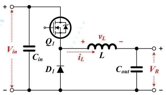
Figure 6.
The basic driving circuit of a contactor with a two-level excitation current.
3.2. Hardware Description
The system that drives the MC should be simple yet highly reliable. The system should also be organized such that it reduces energy losses to improve the durability of the MC. Therefore, this study proposes a two-level excitation current driver that can ensure the high reliability and durability of the MC. This study proposes two types of two-level excitation current drivers, an analog and a digital type, which can be selectively approached depending on the system configuration. Both types of drivers perform operations through the same steps. Step 1: Apply a maximum current that makes the magnetic flux density constant so that the MC can operate in the open state. Step 2: Have a waiting time for the time to transition to a stable decommissioning state. Step 3: After switching to a stable closed state, apply a minimum current to maintain the same magnetic flux density. Additionally, a method of obtaining information on the open and closed circuit of MC through information on the slope of the excitation current and determining the state of MC was applied.
3.2.1. Analog-Type Two-Level Excitation Current Driver
The analog-type two-level excitation current driver is a simple driver like LM2576 that can be implemented using commercially available power supply chips. Currently, numerous companies are producing dedicated chips for small-capacity SMPS, which have the advantage of being inexpensive. Therefore, the economic disadvantages can be overcome by appropriately selecting a small-capacity switching mode power supply (SMPS) chip with a built-in driving circuit.
The characteristics of the LM2576 chip are that it is extremely inexpensive, and it can adjust the output voltage more simply by setting the feedback resistance. Particularly, this chip has the advantage of operating at a high switching frequency of 52 [kHz] and has no problems even when the output is short-circuited, owing to the current-limiting circuit.
Figure 7 shows the proposed two-level electromagnetic contactors driving circuit using LM2576. The proposed driving circuit can be utilized in two ways. The first is a method of driving electromagnetic contactors using the chip on/off terminal of LM2576 with an applied input voltage . This method has the feature that it can be used without an additional driving circuit to drive the MC. The second method involves applying an input voltage to the turned-on LM2576 chip. This method can easily be applied to systems already in use.
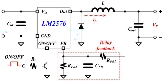
Figure 7.
Proposed analog two-level MC driving circuit using LM2576.
The proposed driving circuit uses a time delay by the R-C circuit and a low-frequency filter in the voltage-feedback circuit to generate a two-level voltage. The delay in the circuit should be set to a value greater than the closing time of the MC. In this circuit, the output voltage is determined by the voltage feedback voltage distribution circuit resistance as follows:
3.2.2. Digital-Type Two-Level Excitation Current Driver
A digital two-level excitation current driver drives an MC using a modified step-down converter. Although the unit cost of the digital-type driver is somewhat higher than that of the analog-type driver, it has the advantage of measuring the status information about the MC to improve reliability. Figure 8 shows the configuration of a modified step-down converter for driving a two-level excitation current driver, which aims to minimize the disadvantage of higher unit cost by eliminating the independent power source for driving the switch. In this topology, the input voltage is applied to the MC excitation coil through the switch when it is turned on, and the power is disconnected through a wheeling diode when it is turned off. Typically, the excitation coil of an MC has a significantly large inductance value; therefore, the current owing to the voltage is characterized by a low-cutoff frequency low-pass filter (LPF).
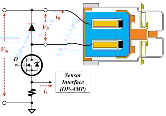
Figure 8.
Proposed digital two-level MC driving circuit.
Figure 9 shows the operating waveform of the proposed digital two-level excitation current driver. As aforementioned, when controlling the exciting current of an MC, it is desirable to drive it at a low switching frequency to reduce losses owing to harmonic currents. As shown in Figure 9, the power switch circuit is driven at a significantly lower frequency than the sampling frequency of the controller; therefore, the controller can measure a current waveform close to the instantaneous current. Using these characteristics, this study applied a method to obtain the open- and closed-circuit information of an MC through the slope information of the excitation current and determine the state of the MC. The slope of the excitation current when the excitation voltage is applied is defined as follows:
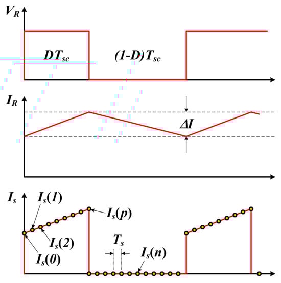
Figure 9.
Operation waveform of digital two-level drivers.
In the drive presented in Figure 9, the voltage applied to the excitation coil was constant because it was applied directly to the input voltage. Therefore, the slope of the excitation current is given by the inductance, which varies with the gap in the MC.
Therefore, by using the measured value of a in Equation (12) and the voltage applied to the inductor using Equation (13), the inductance can be predicted based on the current gap state of the electronic contact, and the open and closed states of the electronic contact can be determined based on the magnitude of this value. Consequently, the state of the MC can be measured using the slope of the current ripple in the inductor, which indicates that the reliability of the system in which the MC is configured can be increased.
4. Simulation and Experiment
As shown in Equation (5), the force of an MC is proportional to the square of the current and inversely proportional to the square of the air gap. Therefore, in an MC with the same excitation current, the force in the closed state is greater than that in the open state. Therefore, in the closed state, the contact can be maintained even if the excitation current is reduced. Therefore, to reduce the driving losses of an MC, it is necessary to reduce the current in the closed state.
Figure 10 shows a schematic of the PSIM simulation used to validate the feasibility of the two-level excitation current driver proposed in this study. The simulated circuit diagram consists of a power component that drives the MC, a control component that controls the two-level excitation current, and a component that detects the operating status of the MC. The state of the MC was configured to calculate the electromagnetic force of the MC using the current and output inductance according to the void state of the magnetic circuit. Figure 11 is the simulation result waveform to confirm the characteristics of the two-level excitation current driver proposed in this paper. The order of the resultant waveforms is as follows, starting from the top: MC applied voltage, MC displacement, current, inductance, reluctance, and driving power. As shown in the resulting waveform, a power-supply voltage of 24[V] is applied directly at the beginning of the MC closing operation.
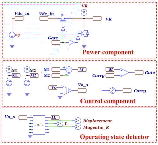
Figure 10.
Simulation circuit for MC operation analysis.
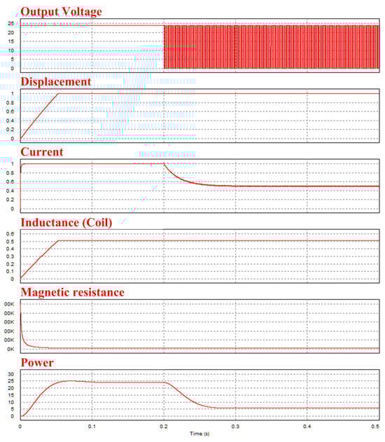
Figure 11.
Simulation result.
A total of 200[msec] after the power was applied and the closing operation was completed, PWM was performed to reduce the excitation current. As a result of the simulation, the current in the closed state was set to of the rated current of the MC, and a driving power reduction of approximately was observed.
A prototype for characterizing the driver proposed in this study is shown in Figure 12. Figure 12a shows an analog-type two-level drive circuit using LM2576 and Figure 12b shows a digital two-level drive circuit using a microcontroller unit (MCU) TMS320F280025. And LS Electric’s MC-65a product was used to verify the actual two-level excitation current control operation.
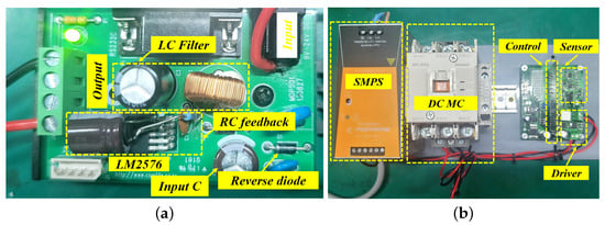
Figure 12.
Proposed two−level excitation current driving circuit. (a) Proposed analog type driving circuit, (b) Proposed digital type driving circuit.
To verify the operational characteristics of the actual MC, the DC-driven MC, power supply, and driver proposed in this study were configured.
Figure 13 shows the waveforms of the experimental results used to compare the characteristics of the conventional control method and two-level excitation current-control driver proposed in this study. The conventional excitation method shown in Figure 13a operates at an excitation current of approximately 2.2[A] when a voltage of 24[V] is applied. To confirm the operating characteristics of MC, an experiment was carried out using a general excitation current method. As a result of the experiment, closing time was measured as 200[msec] and opening time was measured as 300[msec]. Accordingly, two-level excitation current control was performed after 400[msec] to maintain a stable closed state after the MC operation. Figure 13b shows the resulting waveform of the analog two-level excitation current driver. Similar to the previous experiment, the behavioral characteristics of the MC were verified based on an on/off signal. The maximum duty of LM2576 is 0.98, and it operates as the maximum duty in the initial state for turning the MC into a closed state. After the stable closed state, the duty rate is set to be 0.4 after about 400[msec] so that a two-level excitation current is formed. This means that energy efficiency is saved in proportion to the reduction of the excitation current. Accordingly, it may be seen that power is reduced by about 85% when the maximum duty is 0.98 and the two-level excitation current duty is 0.4, for the same input voltage.
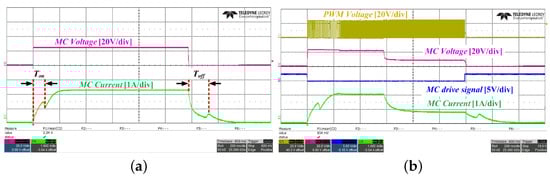
Figure 13.
Comparison of MC driving characteristics. (a) Existing excitation method, (b) Proposed two−level excitation method.
Figure 14 shows the experimental waveforms when an input voltage was applied to the LM2576 chip using an analog two-level drive circuit. The voltage waveform applied by the MC shown in Figure 14a is initially a ramp waveform owing to the capacitor present in the drive circuit. The output voltage becomes 24[V] at the beginning of the closed-loop operation. However, the feedback voltage using the RC filter for control is a monotonically increasing function; therefore, it operates at the maximum duty ratio. When the MC is completely closed, the output voltage is controlled by the PWM to the desired voltage, and the excitation current can be lowered accordingly. Figure 14b shows the waveform of the closed state. It can be observed that the duty ratio is approximately 0.4, which results in a lower excitation current compared with the initial operation.
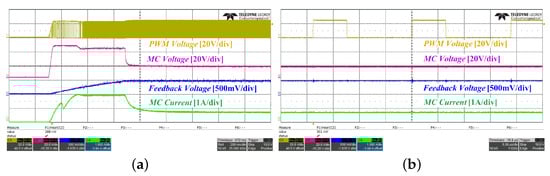
Figure 14.
Experimental result waveform by analog driver. (a) Analog two-level drive circuit result waveform, (b) Analog two-level drive circuit result waveform of the closed state.
Figure 15 shows the resulting waveform for driving an MC using a digital two-level drive circuit. It can be seen that the digital driver normally determines the operating state of the MC, regardless of the excitation current control. This implies that the reliability of a system in which an MC is configured can be increased.
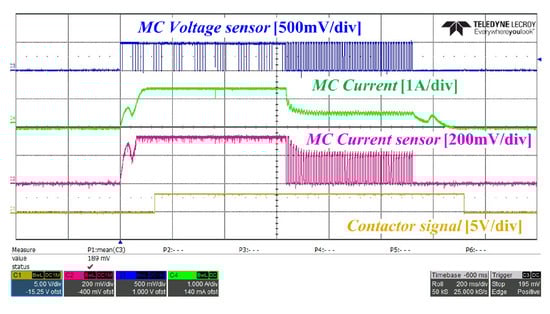
Figure 15.
Experimental result waveform by digital driver.
Figure 16 shows the waveforms used to verify the reliability of the closed state of the MC. Figure 16a shows the resulting waveform when the MC is normally configured, and Figure 16b shows the waveform when the contact operation error is forcibly generated by inserting a 2[mm] insulator into the contact part of the MC. As can be observed from the experimental waveform results, the slope of the excitation current was determined to detect whether it was normal, and the contact status output was confirmed to be normal.
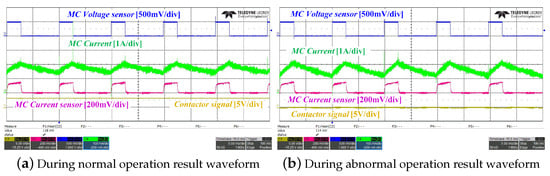
Figure 16.
Characteristics of the closed state of the MC.
5. Conclusions
In this study, a two-level excitation-current-type MC drive that can reduce the drive power using the features of different conditions depending on the driving state of the MC was proposed. The proposed driver operates by applying different excitation currents depending on the operating state, thereby reducing the overall driving power. Moreover, analog- and digital-type topologies were proposed for various applications of the proposed method, and an algorithm that can determine the operation status based on the ripple of the excitation current was applied to increase the operational reliability of the MC. Simulations and experiments were conducted to verify the feasibility of the proposed method, and the following conclusions were drawn:
1. The proposed analog two-level excitation scheme, which uses LM2576 to drive an MC, has economic advantages when applied to existing systems. In addition, the method that uses the on/off control terminal of the LM2576 has the advantage of being implemented in a simple architecture without separate drives.
2. Digital drivers for MCs are available for a wide range of voltages above the MC rating. Furthermore, it has the advantage of ensuring high reliability by detecting contact malfunctions based on the ripple information of the excitation current.
3. Finally, the two-level excitation current driver proposed in this study can reduce the drive power by more than 50–70% compared to the conventional method. Therefore, the power required by the MC can be effectively reduced to reduce the power burden on the system. Further, when used in EVs, it is expected to help improve the driving range by effectively reducing power.
Author Contributions
Conceptualization, R.-Y.K. and S.-K.L.; methodology, S.-K.L.; software, R.-Y.K. and S.-K.L.; validation, T.-H.P. and S.-K.L.; formal analysis, R.-Y.K. and S.-K.L.; investigation, T.-H.P. and S.-K.L.; data curation, T.-H.P. and S.-K.L.; writing—original draft preparation, T.-H.P. and S.-K.L.; writing—review and editing, R.-Y.K. and S.-K.L.; Funding acquisition, S.-K.L.; Project administration, S.-K.L. All authors have read and agreed to the published version of the manuscript.
Funding
This study was supported by research fund from Honam University, 2022 (Grant Number: 2022-0206).
Data Availability Statement
The data presented in this study are available in this article.
Conflicts of Interest
The authors declare no conflicts of interest.
References
- Zhang, L.; Ye, Q.; Zeng, X.; Liu, S.; Chen, H.; Tao, Y.; Yu, X.; Wang, X. Preparation and Properties of Graphene Reinforced Copper Electrical Contact Materials for High-Voltage Direct Current Electrical Contacts. Electronics 2023, 13, 53. [Google Scholar] [CrossRef]
- Lee, H.; Kang, J.W.; Choi, B.Y.; Kang, K.M.; Kim, M.N.; An, C.G.; Yi, J.S.; Won, C.Y. Energy Management System of DC Microgrid in Grid-Connected and Stand-Alone Modes: Control, Operation and Experimental Validation. Energies 2021, 14, 581. [Google Scholar] [CrossRef]
- Uzair, M.; Abbas, G.; Hosain, S. Characteristics of battery management systems of electric vehicles with consideration of the active and passive cell balancing process. World Electr. Veh. J. 2022, 12, 120. [Google Scholar] [CrossRef]
- Langenberg, N.; Kimpeler, S.; Moser, A. Interconnecting Power-Electronic Buck Converter Modules in a Novel High-Power Test Bench for MVDC Circuit Breakers. Energies 2022, 15, 7915. [Google Scholar] [CrossRef]
- Belda, N.A.; Smeets, R.P.P. Test circuits for HVDC circuit breakers. IEEE Trans. Power Deliv. 2016, 32, 285–293. [Google Scholar]
- Ke, Y.; Zhang, W.; Suo, C.; Wang, Y.; Ren, Y. Research on low-voltage AC series arc-fault detection method based on electromagnetic radiation characteristics. Energies 2022, 15, 1829. [Google Scholar] [CrossRef]
- Lee, K.A.; Cho, Y.M.; Lee, H.J. Circuit model and analysis of molded case circuit breaker interruption phenomenon. Electronics 2020, 9, 2047. [Google Scholar] [CrossRef]
- Li, Z.; Jiang, X.; Xu, W.; Gong, Y.; Peng, Y.; Zhong, S.; Xie, S. Performance comparison of electromagnetic generators based on different circular magnet arrangements. Energy 2022, 258, 124759. [Google Scholar] [CrossRef]
- Peng, Y.; Xu, W.; Gong, Y.; Peng, X.; Li, Z. Electromechanical coupling of a 3.88 W harvester with circumferential step-size field: Modeling, validation and self-powered wearable applications. Smart Mater. Struct. 2024, 33, 025039. [Google Scholar] [CrossRef]
- Bensalah, A.; Barakat, G.; Amara, Y. Electrical generators for large wind turbine: Trends and challenges. Energies 2022, 15, 6700. [Google Scholar] [CrossRef]
- Jo, K.Y.; Duong, T.D.; Choi, J.H. Emerging technologies in power systems. Electronics 2021, 11, 71. [Google Scholar] [CrossRef]
- Bento, A.R.F.; Bento, F.; Cardoso, A.J.M. A review on Hybrid Circuit Breakers for DC applications. IEEE Open J. Ind. Electron. Soc. 2023, 4, 432–450. [Google Scholar] [CrossRef]
- Bak, H.J.; Ro, J.S.; Chung, T.K.; Jung, H.K. Characteristics analysis and design of a novel magnetic contactor for a 220 V/85 A. IEEE Trans. Magn. 2013, 49, 5498–5506. [Google Scholar] [CrossRef]
- Gabdullin, N.; Ro, J.S. Energy-efficient eco-friendly zero-holding-energy magnetic contactor for industrial and vehicular applications. IEEE Trans. Veh. Technol. 2020, 69, 5000–5011. [Google Scholar] [CrossRef]
- Sun, S.; Cui, J.; Du, T. Research on the influence of vibrations on the dynamic characteristics of ac contactors based on energy analysis. Energies 2020, 13, 559. [Google Scholar] [CrossRef]
- Zeng, G.; Yang, X. Analysis, Design, and Optimization of a Novel Asymmetrical Bistable Short Mover Permanent Magnet Actuator for High-Voltage Circuit Breaker Application. Actuators 2022, 11, 196. [Google Scholar] [CrossRef]
- Nascimento, R.; Ramos, F.; Pinheiro, A.; Junior, W.D.A.S.; Arcanjo, A.M.; Filho, R.F.D.; Mohamed, M.A.; Marinho, M.H. Case Study of Backup Application with Energy Storage in Microgrids. Energies 2022, 14, 9514. [Google Scholar] [CrossRef]
- Wang, G.; Wang, Y.; Zhang, L.; Xue, S.; Dong, E.; Zou, J. A novel model of electromechanical contactors for predicting dynamic characteristics. Energies 2021, 14, 7466. [Google Scholar] [CrossRef]
- Rahman, R.; Bandyopadhyay, S. The cost of energy-efficiency in digital hardware: The trade-off between energy dissipation, energy–delay product and reliability in electronic, magnetic and optical binary switches. Appl. Sci. 2021, 11, 5590. [Google Scholar] [CrossRef]
- Fang, S.; Chen, Y.; Yang, Y. Optimization design and energy-saving control strategy of high power dc contactor. Int. J. Electr. Power Energy Syst. 2020, 117, 105633. [Google Scholar] [CrossRef]
- Jiang, J.; Lin, H.; Fang, S. Multi-objective optimization of a permanent magnet actuator for high voltage vacuum circuit breaker based on adaptive surrogate modeling technique. Energies 2019, 12, 4695. [Google Scholar] [CrossRef]
- Kazimierczuk, M.K.; Sekiya, H. Design of AC resonant inductors using area product method. In Proceedings of the 2009 IEEE Energy Conversion Congress and Exposition, San Jose, CA, USA, 20–24 September 2009; pp. 994–1001. [Google Scholar]
- Cho, Y.M.; Park, H.J.; Lee, H.J.; Lee, K.A. Analysis of Short-Circuit and Dielectric Recovery Characteristics of Molded Case Circuit Breaker according to External Environment. Electronics 2022, 11, 3575. [Google Scholar] [CrossRef]
- Riba, J.R.; Garcia, A.; Cusidó, J.; Delgado, M. Dynamic model for AC and DC contactors–simulation and experimental validation. Simul. Model. Pract. Theory 2011, 19, 1918–1932. [Google Scholar] [CrossRef]
- Tang, L.; Qu, H.; Xu, Z. Research on double closed-loop control strategy of contactors based on flux linkage observers. IEEE Trans. Ind. Electron. 2021, 69, 2769. [Google Scholar] [CrossRef]
- Rahman, A.; Mizuno, T.; Takasaki, M.; Ishino, Y. An equivalent circuit analysis and suspension characteristics of AC magnetic suspension using magnetic resonant coupling. Actuators 2020, 9, 52. [Google Scholar] [CrossRef]
Disclaimer/Publisher’s Note: The statements, opinions and data contained in all publications are solely those of the individual author(s) and contributor(s) and not of MDPI and/or the editor(s). MDPI and/or the editor(s) disclaim responsibility for any injury to people or property resulting from any ideas, methods, instructions or products referred to in the content. |
© 2024 by the authors. Licensee MDPI, Basel, Switzerland. This article is an open access article distributed under the terms and conditions of the Creative Commons Attribution (CC BY) license (https://creativecommons.org/licenses/by/4.0/).