1. Introduction
TSN has become an integral part of modern industrial communication, automation, and automotives communication. It enables strict deadlines in automation and synchronous communication along with coordination between machines in industry 4.0. Similarly, TSN fulfills prioritized communication with strict quality-of-service requirements in the automotives industry, e.g., automated self-driving vehicles, where machine response times in the order of microseconds are required. With 5G release 16 and 17, 5G systems are also capable of providing TSN services enabling a wide range of remote healthcare services, e.g., remote operation procedures, too. While 5G standards incorporate TSN functionality, it also significantly adds to the complexity of the 5G system; therefore, there are very limited available implementations of the 5G system which integrate TSN in hardware or in software.
One of the first steps in TSN-5G integration is to support the time synchronization of TSN devices through the 5G network. Since TSN time synchronization messages are based on Ethernet frames, they cannot be carried through a 5G network unless it supports Ethernet PDU transport. A possible workaround is to encapsulate the Ethernet PDUs within IP PDUs. We therefore implemented the encapsulation of Ethernet frames in UDP/IP packets in the OMNeT++ based Simu5G simulator, as it so far only supports an IP PDU transport.
The major contributions of this paper are as following:
Integration of time synchronization for TSN in a 5G Simulator framework model;
Performance simulation for TSN time synchronization through 5G downlink;
Performance simulation for TSN time synchronization in a 5G handover scenario;
Analysis of factors impacting synchronization accuracy in 5G network.
The sections are structured as follows.
Section 2 describes the basics of TSN along with the time synchronization procedure of the TSN standard.
Section 3 gives an overview of the current research in the field of TSN time synchronization using the 5G network as a communication link. The integration of TSN and 5G, with a focus on time synchronization, is given in
Section 4. It also discusses the implementation of various models and simulation scenarios created, using those models to evaluate the performance of TSN time synchronization using encapsulation over the 5G system (5GS).
Section 5 analyzes the result of the simulations. And finally,
Section 6 concludes the paper.
2. Time-Sensitive Networking
Time-Sensitive Networking (TSN) standards enable determinism, ultra-reliable and low latency communication in Ethernet networks and being the industry standard ensures interoperability between manufacturers. The TSN standards encompass various extensions for the IEEE 802.1Q standard [
1] for VLANs in bridged networks. As TSN mainly focuses on real-time communication in bridged networks, its standards are separated into four major categories, each aiming to guarantee quality of service to specific real-time traffic. These main categories are Time Synchronization to synchronize all network devices to a network master, Bounded Low Latency for deterministic end-to-end latency in the network, Ultra-Reliability for data prioritization with end-to-end route reservation in addition to path redundancy, and Resource Management for managing the network devices through a network devices coordinator and configurator.
Table 1 gives an overview of TSN standards in each of the mentioned categories.
Each TSN component is briefly described in the next subsections. Time synchronization is discussed in detail as it is crucial for understanding the simulation results presented later in
Section 5.
2.1. Resource Management
Resource Management in a TSN network is realized via various protocols and standards, each optimizing and managing specific functionality on the TSN core and end-devices. The Stream Reservation Protocol (SRP) (IEEE 802.1Qat standard) provides the basis of reserving the network resources from the talker to the listener. SRP implements a decentralized stream reservation procedure, in which the listener and the talker directly communicate to reserve resources for the streams. While this reserves the streams, there might arise situations where stream reservations between different talkers and listeners try to overrule each other, resulting in poor performance of all of the streams. Therefore, IEEE 802.1Qcc implements enhancements to SRP standard that make SRP centralized by running the reservation protocol on a Centralized Network Configurator (CNC). Having information about the complete network topology, CNC is able to centrally assign path resources, e.g., low latency queues, interface bandwidth, and high priority gates, to the specified stream between the talker and listener. CNC, depending on the network topology information, computes Gate Control Lists (GCLs) via user-defined algorithms and device configuration files using YANG (a UML-based data modeling language). These configurations are then pushed to the respective devices via NETCONF. Meanwhile, RESTCONF can be used for the User Network Interface (UNI) to configure the CNC.
The IEEE standards 802.1Qcp, Qcw and Qcbcv define YANG models for the CNC to configure the bridging, traffic scheduling, filtering, frame replication and elimination functionality for TSN bridges.
2.2. Bounded Low Latency
Ensuring that data packets reach the destination within the application specified time requirements is of utmost importance in real-time networks. TSN makes use of VLAN Tagging and implements extensions to IEEE 802.1Q standard.
To achieve guaranteed end-to-end latency, traffic shaping standards are used to reduce the buffering of frames in bridge devices. A Credit-Based Shaping (CBS) mechanism is defined in IEEE 802.1Qav [
2], which allows bandwidth reservation for up to eight distinct traffic classes. Each traffic queue is assigned a class and is associated with an idleSlope parameter that adds credits to the queue, which are required to transmit frames. Depending on the queue class and the number of frames in the queue, credits are increased or decreased and depending on the available credits; frames from the queue are forwarded.
A Time-Aware Scheduling mechanism is defined in IEEE 802.1Qbv [
3]. Time-Aware Shaper (TAS) adds a transmission gate to each queue, which opens and closes, allowing the transmission of frames. The state of the gates is controlled by a Gate Control List (GCL), which is computed by CNC. The entries in the GCL are set as the current configuration for a specified time, beginning with the first entry. After all entries have been applied, the cycle is repeated.
Frame pre-emption is defined in IEEE 802.1Qbu, allowing the interruption of low-priority frame transmission if a high-priority frame is received for forwarding.
2.3. Ultra-Reliability
TSN extends the 802.1Q Bridging standard and adds Path Control and Reservation (PCR) as well as Per-Stream Filtering and Policing (PSFP) standards to guarantee reliable frame delivery between source and destination. PCR extends Shortest Path Forwarding (SPF), which is based on Intermediate System–Intermediate System (IS-IS) protocol to Explicit Paths Determination using the Path Computation Element. This allows the CNC to have granular control of paths and to reserve paths for streams with high reliability requirements. Reserved paths could be point to point, point to multipoint, or multipoint to multipoint connections.
Frame Replication and Elimination enables TSN bridges to duplicate the frames and transmit over alternative paths to ensure reliability. The TSN bridge at the receiving end then eliminates the duplicate frames and forwards the remaining frames to the destination. PSFP adds ingress traffic policing to the bridges via filtering based on predefined rules which can be streamID matching, priority-level matching, service class selection, or even frame counting.
2.4. Time Synchronization
Time synchronization is a key requirement of real-time networks; thus, it is of utmost importance and a basic component of TSN. It enables TSN devices to adjust and correct their local clocks in reference to the Grand Master clock. This is a prerequisite for gate-scheduling mechanisms, path reservation, traffic filtering and forwarding and traffic shaping via TAS or CBS. Time synchronization for TSN is standardized in IEEE 802.1AS with the gPTP profile for the IEEE 1588v2 Precision Time Protocol (PTP). It provides sub-microsecond accuracy in synchronization. The time synchronization mechanisms are shown in
Figure 1.
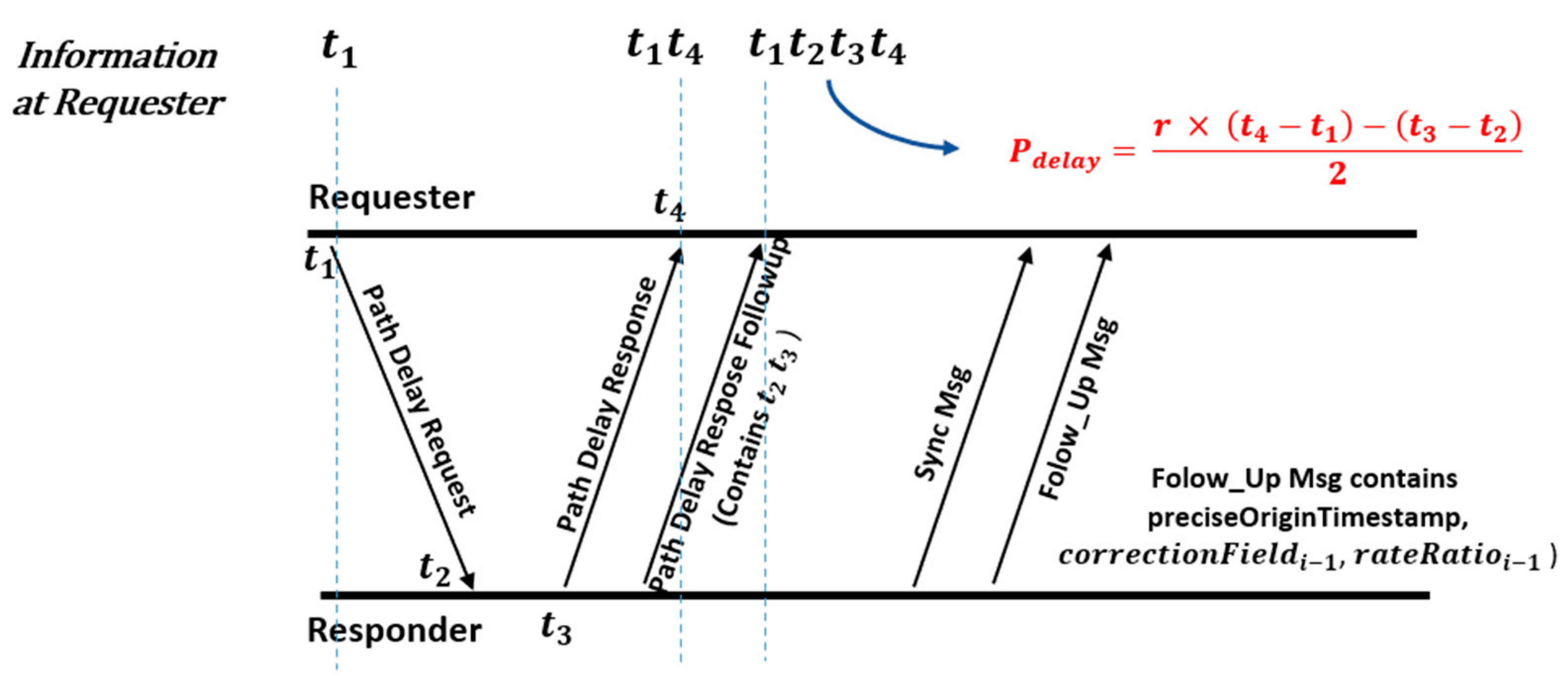
In
Figure 1, ‘r’ is the ratio of the clock oscillator frequencies of the Requester and the Responder node. Since each node has an oscillator drift, i.e., oscillator frequencies of nodes are different, the rate ratio is used to establish a common frequency baseline during Propagation Delay calculation.
The synchronization procedure consists of the Requester entity (TSN device which wants to synchronize to the master) requesting the Responder entity (TSN device to which all other TSN devices synchronize to) to initialize the synchronization process. After initialization, the Requester sends a path delay measurement request to the Responder, which responds with a path delay measurement response and a follow-up message. In this three-message exchange, the Requester gathers four timestamps, as shown in
Figure 1. In the propagation delay measurement process, a symmetric link is assumed. This is true for wired networks, but for wireless networks, with asymmetric links, this assumption can adversely affect the outcome of the synchronization, as we will see in the
Section 5 of this paper.
After the propagation delay measurement process, a synchronization message and a synchronization follow-up message are sent by the Responder with the current timestamp (preciseOriginTimestamp). Using the current time, the previously computed propagation delay, and the correction field (in case if the Responder is not the Grand Master), the Requester computes the actual time using the following equation and adjusts its local clock accordingly.
For integration of TSN and the 5G network, it is important for the 5G network to provide the required QoS to the TSN communication streams. This also implies that the time synchronization messages of the TSN network shall traverse through the 5G system in order for TSN end devices on the either side of 5GS to synchronize. But the handovers in 5GS and channel access grants for UE to access the channel for data transmission result in irregular propagation delay calculations, which decreases the synchronization accuracy as compared to a symmetric 5G link, i.e., there is the same propagation delay in uplink and downlink.
IEEE 802.1AS being a Layer 2 protocol generates Ethernet frames, and with the 5G TSN integration, the 5G system must support the Ethernet PDU transmissions over the 5G network. In addition, the 5G system can have its own Grand Master keeping the TSN and 5G time domains separate. Thus, TSN synchronization frames traversing through the 5G network must also be updated with the ingress and egress timestamps, which is a function of the Network Side–Time Translator (NW-TT) and Device Side–Time Translator (DS-TT) entity in the 5G network. Furthermore, being in the different time domains, correction fields of the synchronization that might be passing through the 5G system also need to be updated.
In addition to Ethernet PDU support, DS-TT, and NW-TT functionality, the mapping of TSN QoS values to the 5G QoS values (5QI) is also required. This is achieved via the mapping tables and communication between the 5G TSN Application function and TSN Central Network Configurator (TSN CNC).
3. Related Research
3GPP Release 16 and 17 integrate TSN functionality in 5G networks. This is an active and evolving research area, and TSN 5G integration is not feasible until time synchronization between TSN devices over 5G does not fulfill the accuracy requirements of the IEEE 802.1AS standard.
In [
4], Thi et al. created TSN over Wi-Fi and over 5G mobile networks using common off-the-shelf (COTS) devices. They tested the networks for single-hop and two-hop performance of 802.1AS over wireless links and found that with COTS devices, successful synchronization, that meets the standards of Industrial TSN (sub-microsecond accuracy), cannot be achieved. Their results show a time synchronization accuracy of up-to 2.5 milliseconds in best-case scenarios for 5G links. They also show that due to the variations in the jitter and the measured propagation delay, accurate synchronization is not achieved.
Gundall et al. in [
5] implemented 802.1AS-based time synchronization over 5GS in a hardware test setup. Their findings state that <1 millisecond accuracy can be achieved with 802.1AS time synchronization over 5G.
Shi et al. [
6] published an analytic framework and showed that sub-microsecond accuracy can theoretically be achieved, if different errors, such as error in path delay estimation and error in time of arrival estimation, associated with reference time indication are minimized. They also mention that variations and errors in propagation delay estimation can have significant impact on the synchronization accuracy as we show in our simulations.
Schüngel et al. in [
7] present a formulation method for error computation in time synchronization mechanisms for TSN and 5G integration. The paper considers a maximum error of 50.5 nanoseconds for propagation delay measurement, and a symmetric 5G link is assumed. Their model calculated synchronization errors of up to 8 ns after successful synchronization. The paper focuses on minimizing the error rate during synchronization while assuming a 50 nanoseconds symmetric link delay in wired and wireless links, which is unrealistic.
The next section describes the method implemented and used for synchronizing TSN devices over a 5G network and the scenarios simulated to test the synchronization accuracy.
4. Simulation Setup for TSN Synchronization over 5G Scenarios
5G Release 16 supports TSN time synchronization by enabling the 5GS as a TSN bridge. The entire end-to-end 5GS is considered a Time-Aware System, meaning that the 5G system is able to provide time-critical services to TSN. Only the edges of the 5GS must support IEEE 802.1AS operations, while inside 5GS, a separate synchronization mechanism is used for the 5GS specific elements. As a Time-Aware System, 5GS calculates and adds the measured residence time between its network edges to the correction field of the synchronization messages.
3GPP Release 17 adds a Time Translator (TT) functionality on the edges of 5GS—the so-called Network-Side TT (NW-TT) and Device-Side TT (DS-TT). NW-TT and DS-TT update the rateRatio fields of the passing though synchronization messages. RateRatio is the ratio of clock oscillator frequencies of the master and the slave node. It is used to update the gathered timestamps to the common time base. To compute the residence time, the 5GS ingress side (i.e., the 5G component which receives the sync messages which are to be forwarded over the 5GS) adds an ingress timestamp to the sync messages. When the message is leaving the 5GS, the TT at the egress side adds the egress timestamp in the message. Upon reception of the message at a TSN device, the egress and ingress timestamps are used to calculate the time that the message spent within the 5GS. This residence time is used in the correction field calculations during the synchronization process. Although the procedures for TSN time synchronization over a 5G system are standardized, the propagation delay measurement still assumes symmetric uplink and downlink, which could introduce errors and reduce the synchronization accuracy significantly. A way to cater to the asymmetry could be using the averaged downlink timestamps from the previous synchronization cycles for the synchronization in downlink. A similar process can be performed for synchronization in uplink.
Very few tools are available to simulate 5G networks and Time-Sensitive Networks together. While NS-3 [
8], Riverbed [
9] and OMNeT++ can be used to simulate TSN functionality, and NYUSIM [
10], Vienna LTE Simulator [
11,
12], WiSE [
13], etc. can be used to simulate 5G functionality [
14], only OMNeT++ offers both TSN and (at least partially) 5GS simulation capabilities.
4.1. OMNeT+ Based Simulation Framework
Our simulation studies were carried out with the discrete event simulator OMNeT++ [
15]. OMNeT++ has various frameworks, which provide different functionalities—for example, the Simu5G [
16] framework comprises basic 5G user plane functions. INET [
17], another major OMNeT++ framework, includes a OSI layer model and multiple protocol options for these layers. INET also contains Time-Sensitive Networking functionality at the Data Link Layer. Therefore, for the simulation studies presented in this paper, both the Simu5G and the INET framework are used as the base. Using these frameworks, new nodes are created which contain both 5G NIC and Ethernet NIC for TSN. The already existing 5G UE model in Simu5G is updated to include time synchronization functionality, and a TSN Bridge model, from the INET framework, is updated with a modified 802.1AS functionality (sync message encapsulation in UDP/IP packets) so that time synchronization messages can be forwarded through the 5GS (which in Simu5G only supports the transmission of IP PDUs).
4.1.1. Updated 802.1AS Model
The 802.1AS model in the INET framework implements the time synchronization mechanism exactly as mentioned in the previous section. The TSN nodes which forward TSN messages into the 5G network and vice versa need to be updated. The encapsulation and decapsulation of time synchronization messages into layer 3 (UDP/IP) PDUs have to be implemented. The sync frames are forwarded, encapsulated within IP PDUs in the 5GS, and once they reach the 5G TSN boundary, decapsulation is performed, and further forwarding in the TSN network relies on layer 2 (MAC) addressing. This means that encapsulation is performed at the ingress 5G TSN boundary node and decapsulation is performed at the egress boundary node. Furthermore, depending on the TSN Grand Master positioning in the simulation scenario, 5G TSN boundary nodes can be set up as ingress or egress boundary nodes in the updated 802.1AS model. This is used in simulating time synchronization scenarios, where the TSN Grand Master can be located in either uplink or downlink; thus, the synchronizing device would be located on the opposite side of the 5G network.
4.1.2. 5G-TSN Device
The INET framework contains a TSN Bridge model, which is inherently an Ethernet switch with TSN functionality. For 5G TSN integration and TSN frames being forwarded over a 5G network using IP PDUs, layer 3 functionality is required at the boundary devices. Since TSN Bridges do not provide layer 3 addressing, the existing INET Ethernet Router model is extended to include TSN functionality for layer 3 forwarding, encapsulation, and decapsulation. In addition to TSN functionality, 5G NIC is also added in the model, so it also can be used as a 5G UE instead of separately updating Simu5G’s UE model to incorporate TSN time synchronization functionality. Finally, as the router has to receive, process, and forward time synchronization frames, the updated 802.1AS model mentioned in the previous subsection is added in the created device model.
4.2. Simulation Scenarios
Using the updated models, two simulation scenarios are created, starting with a simple TSN network consisting of two TSN switches and a Grand Master (GM). The GM, called the TSN Master, is connected to the first TSN switch (based on the 5G-TSN device model), which is in turn connected to the second TSN switch (also based on the 5G-TSN device model). The link between both switches is simulated by a 5G network.
Each TSN device in the simulation has its own clock based on the Constant Drift Oscillator model provided by the INET framework. INET has three Oscillator models: Ideal Oscillator, generating ticks periodically with constant length, Constant Drift Oscillator, generating variable ticks whose length is proportional to the elapsed simulation time, and Random Drift Oscillator, generating clock drift with the random walk process. All of these Oscillator models generate ticks, with tick length varying as mentioned before, which are counted by the clock model to compute the time for that specific clock module.
For TSN, especially for Time Synchronization simulations, Constant Drift Oscillator provides the closest oscillator behavior to the real-world scenarios since the clock either ticks a bit faster or a bit slower than the actual time. Therefore, both simulation scenarios presented in the paper add a Constant Drift Oscillator for the internal clocks of all TSN devices. The TSN Master clock oscillator also contains the drift; thus, the slaves only correct their internal clock drifts with synchronization.
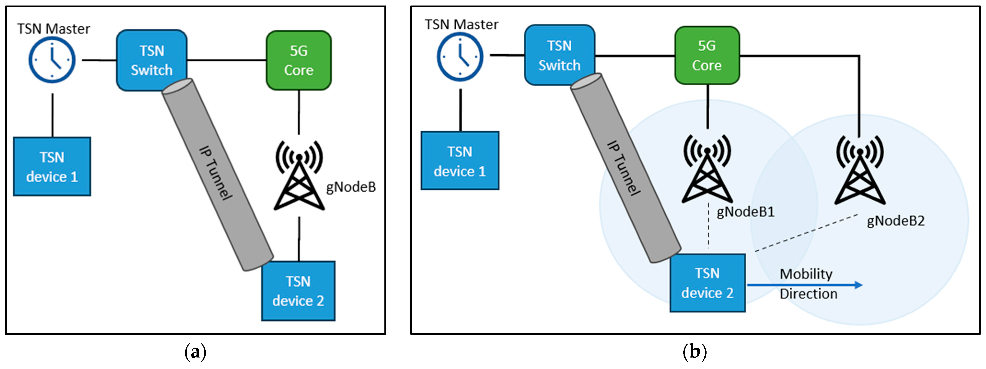
4.2.1. Simulation Scenario 1
In the first scenario, the GM is placed on the server side of the 5G network. That means synchronization messages are transferred in the downlink. Both TSN switches are 5G-TSN devices; the first, named TSN Switch, encapsulates the time synchronization messages and forwards them to the 5G network. The second 5G-TSN device, named TSN device 2, acts as a TSN device capable of synchronizing to the GM through the 5G network. It receives encapsulated time synchronization messages, decapsulates them and synchronizes itself with the GM via the extracted messages. From the perspective of TSN devices, the 5G network is simply a link between TSN Switch and the TSN device 2. This simulation scenario is shown in
Figure 2a.
The scenario can be expanded by connecting TSN devices to the GM (TSN Master), TSN Switch, and TSN device 2 if it takes the role of a TSN Bridge in
Figure 2a, resulting in a hierarchical structure.
4.2.2. Simulation Scenario 2
This scenario is similar to scenario 1 in terms of the TSN network layout but differs in the layout of the 5G network. The 5G network now has two gNodeBs. The TSN device 2 is mobile and moves along a predefined path at a constant speed. This results in a handover between the gNBs, and while the handover is taking place, the synchronization process is affected due to the variation in the propagation delay. This simulation scenario is shown in
Figure 2b.
Both simulation scenarios are run for 500 s. Time synchronization occurs in 1 s intervals, and the propagation delay measurement interval is also set to 1 s. TSN device 1, TSN Switch, and TSN device 2 synchronize to the TSN Master, and the local device’s clock times of the master clock and the slave clocks, immediately before and after synchronization, are logged. In addition, propagation delay, residence time, and all four timestamps required for propagation delay measurement are also logged. Since these timestamps are used to calculate the link delay, they can be used to measure uplink and downlink delay, the delay variations, and the difference between uplink and downlink delay in the 5G network.
The major simulation parameters are shown in
Table 2. Simulation scenario 2 is an extension of simulation scenario 1—therefore, the same parameters as in simulation scenario 1 are applied as well as additional mobility and handover specific parameters.
Both simulation setups are intentionally kept simple, as they will provide the baseline for how the time synchronization performs if there is not any background traffic or when the wireless channels are not saturated. But as the next sections will show, even with the simplest scenarios, the TSN time synchronization through the 5G network using UDP/IP encapsulation does not perform well; simulating more complex scenarios only reduces the time synchronization accuracy.
5. Simulation Results and Discussion
5.1. Simulation Scenario 1
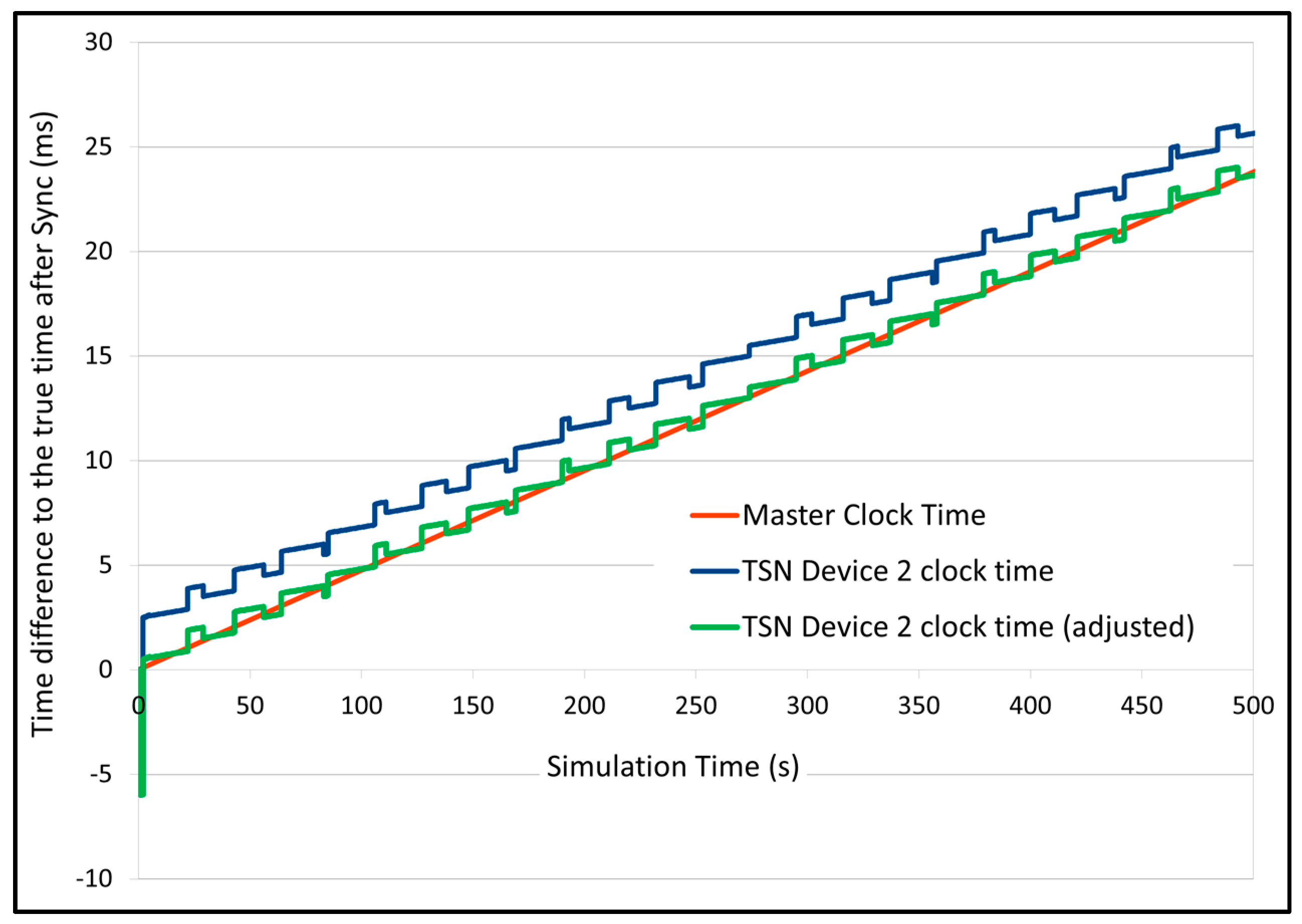
The TSN Switch directly synchronizes to the master via the Ethernet link. The time difference between its clock and the master’s clock, after synchronization, is in the order of 100 nanoseconds, thus indicating a normal successful time synchronization. However, the results of the TSN device 2 synchronization show a lower accuracy.
Figure 3 shows the clock time differences of the master clock (red line) and TSN device 2’s clock (blue line) to the true time. (True time is the actual simulation time, and all the nodes in simulation, including TSN Master, have a constant drift.) It can be seen that the difference between the TSN Master graph and TSN device 2 graphs is approx. 2.5 milliseconds, which means that after synchronization, TSN device 2 still has a 2.5 ms difference from the master’s clock time. This low accuracy is explained by
Figure 4.
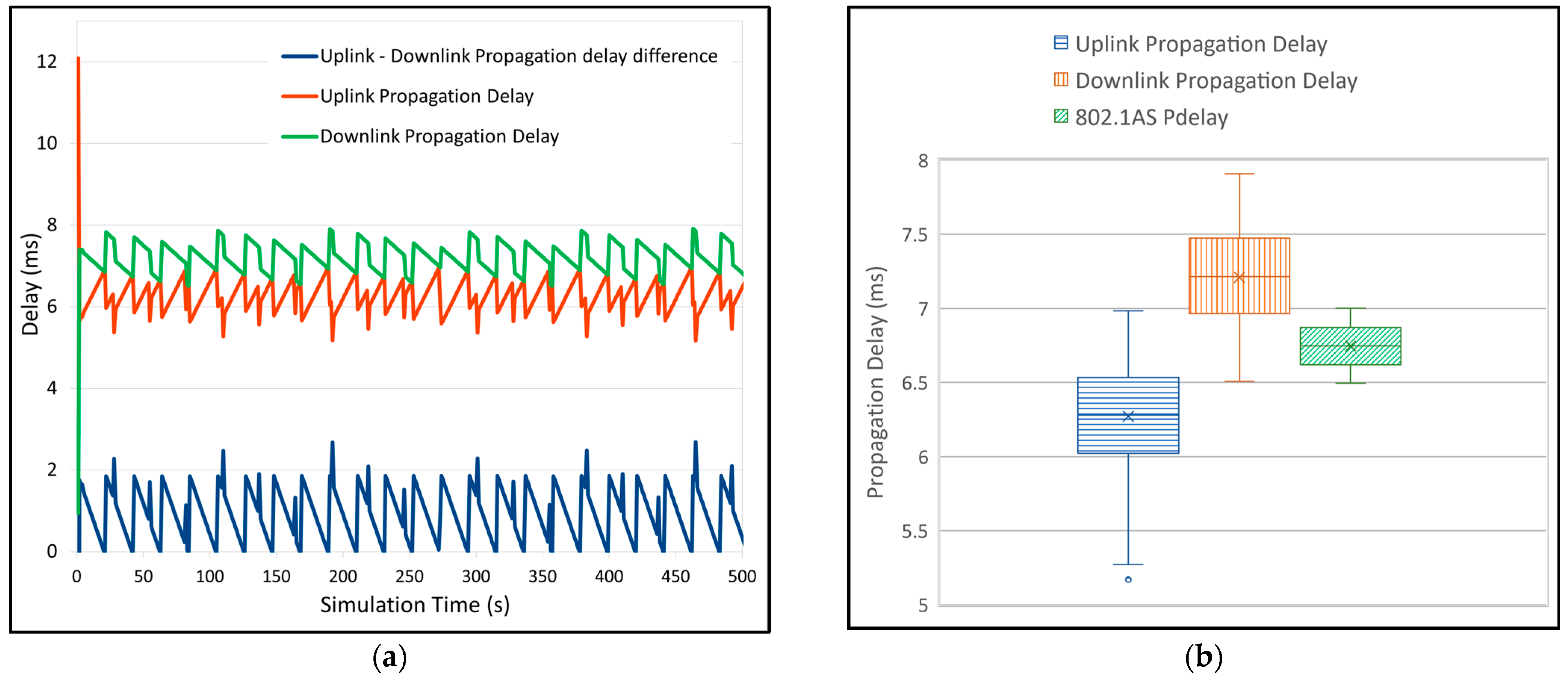
Figure 4a shows the uplink propagation time, downlink propagation delay, and their difference. The 802.1AS standard assumes a symmetric link in terms of propagation delay and computes the average propagation delay, which is used for synchronization. But with a 5G network, the uplink and downlink propagation delay is asymmetric, which is mainly because of the differences in the medium access control (MAC) for uplink and downlink traffic, resulting in an error in propagation delay computation, which in turn affects the accuracy of synchronization.
Figure 4b shows the box plot of the uplink and downlink delay as well as the actual propagation delay calculated by the 802.1AS model. From
Figure 4, it can be seen that the maximum difference between uplink and downlink propagation delay is approx. ~2 ms. If this difference is considered in the propagation delay calculation, the time difference between TSN device 2 and the Master, after synchronization, reduces to ~0.4 ms at maximum (see
Figure 3—TSN device 2 clock time (adjusted)), which is still quite high. The variability of the time difference can be explained by the variability of the uplink and the downlink propagation delay, as seen in
Figure 4.
The reason for propagation delay differences in the uplink and downlink is the process of how 5G UE obtains access to the channel for uplink transmissions. The UE can only transmit in the uplink when the channel grants are given to the UE, resulting in longer delays which in turn results in asymmetric uplink and downlink propagation delay. Furthermore, QoS support is also absent in the Simu5G framework, which further reduces the accuracy during synchronization since sync messages cannot be tagged as high-priority messages.
5.2. Simulation Scenario 2
In simulation scenario 2, the TSN Switch synchronizes to the GM via the Ethernet link and forwards the synchronization frames to the TSN device 2. The TSN device 2 moves from the left to the right side of the simulation area as shown by the mobility direction arrow in
Figure 2b. During the movement, a handover from gNodeB1 to gNodeB2 takes place.
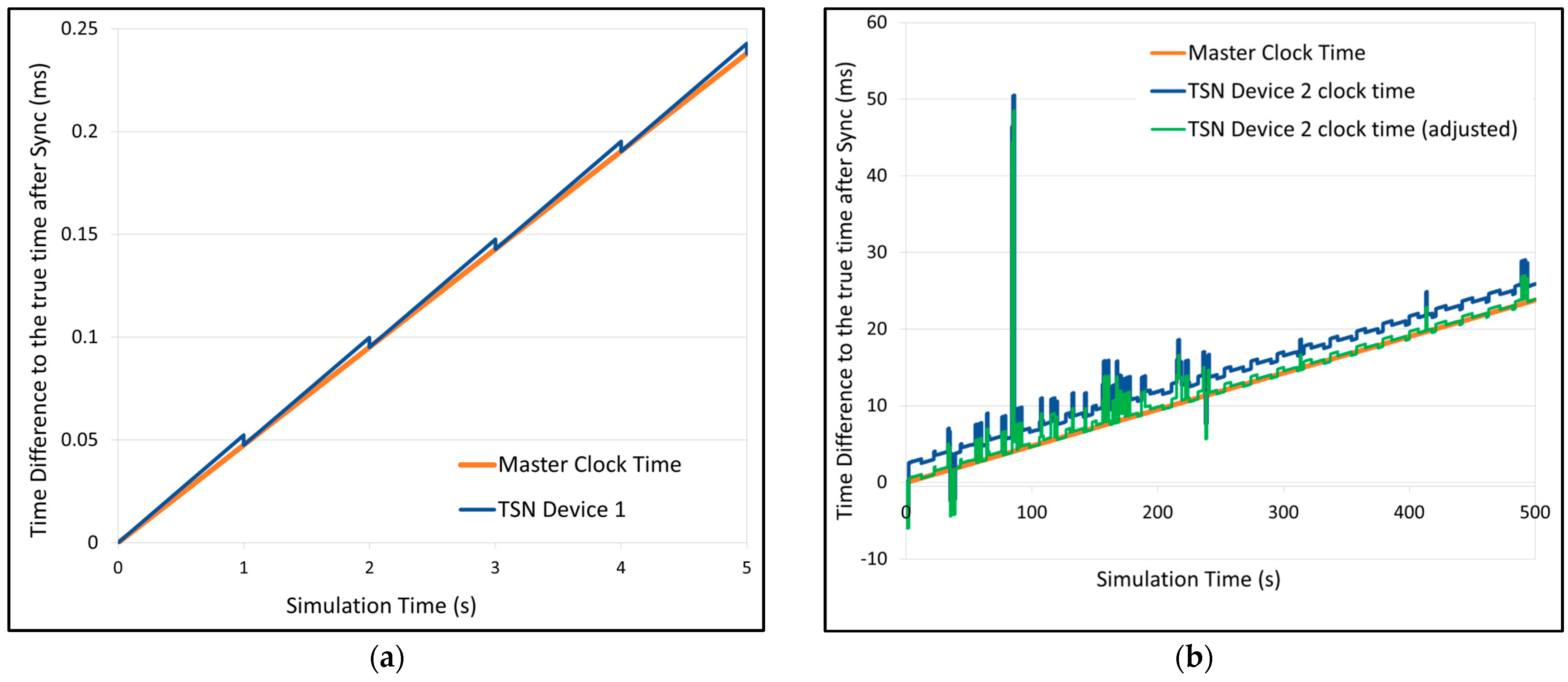
Figure 5a shows the time differences of the TSN Master and TSN device 1 clock to the true time for the first 5 s of simulation. The time difference after synchronization is in order of 100 nanoseconds, indicating a successful synchronization, as expected due to the direct 1 Gbps Ethernet link between them.
Figure 5b shows the true time differences of the TSN Master and the TSN device 2 after synchronization. The handover event at around 95 s is clearly visible, as the difference of the TSN device 2 to the true time suddenly increases to 50 ms, and the difference between the TSN Master and TSN device 2’s clocks is approx. 46 ms. The true time differences of the TSN Master and TSN device 2 before and after the handover event are also higher than the true time differences of the TSN Master and the TSN device 1. This is (like in scenario 1) due to uplink and downlink propagation delay differences. The main reason for the multiple, shorter than the highest delay difference peaks, after the handover are Layer 2 retransmissions between gNodeB and TSN device 2. Since the TSN device has just entered the coverage area of gNodeB2, therefore, L2 retransmissions of erroneous frames cause multiple smaller peaks, which disappear when the device reaches closer to gNodeB2.
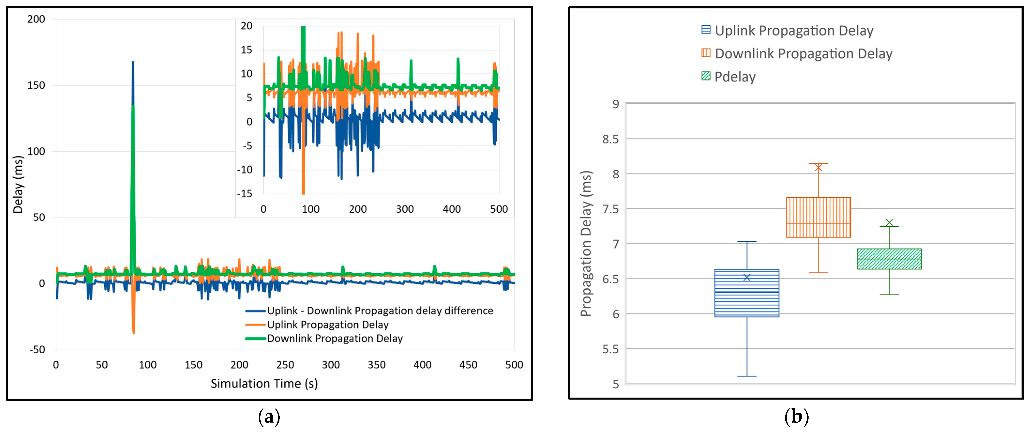
Propagation delays in uplink and downlink direction are shown in
Figure 6. An asymmetry regarding the uplink and downlink delays can be observed (similar to simulation scenario 1) as well as delay variations (caused by L2 retransmissions in a 5G network), resulting in an increased inconsistency of PDelay in its measurement. This in turn leads to a significant time difference between the TSN device 2 and the TSN Master after synchronization. The downlink and uplink delay asymmetry still remains in the simulation as discussed in the previous section, and it is often pronounced due to retransmissions, e.g., in
Figure 6a between 150 and 250 s. Eventually, if in the PDelay calculation, the difference of uplink and downlink delay is considered, the average time difference between TSN device 2 and TSN Master reduces to be 681.86 microseconds (431.55 µs without handover peaks) on average with some irregularities during handover and retransmissions.
A possible solution to avoid synchronization errors during handover is to halt the time synchronization process during the handover process, since synchronizing during handover results in false clock time for the slaves. Once the handover is completed, the synchronization process can be started again with the new Sync and PDelay calculation frames.
The findings from both simulations align with the results that were achieved by [
1,
2], as mentioned in
Section 3.
6. Conclusions
Asymmetry in uplink/downlink propagation delay can adversely affect the synchronization process (because of the PDelay calculation, which assumes symmetry). Furthermore, changing radio conditions and the uplink medium access mechanism (which uses uplink grants) in a 5G network and Layer 2 retransmissions might result in large differences between uplink and downlink delay. Since the PDelay calculation (in 802.1AS) assumes uplink/downlink symmetry and averages the propagation delay in the uplink and downlink direction, any delay asymmetry leads to time synchronization errors. Thus, the need for PDelay correction, before synchronization takes place, arises.
The results of both simulation scenarios implicate that for the TSN 5G integration, strict scheduling and communication between 5G’s Application function that deals with TSN and TSN CNC is required in addition to Time Translator functionality and Ethernet PDU support in 5GS. These functions play an important role in prioritizing the TSN traffic over 5G, allowing the 5GS to align its component’s schedules in line with TSN’s requirements and mapping TSN QoS flows to 5QI flows. For now, the presented simulation models can be used to create a baseline for how time synchronization performs in the native 5GS via UDP/IP encapsulation without QoS. These results can be then compared with QoS support on 5GS for time synchronization frames and with 5GS with complete TSN support.
The main challenges for the time synchronization, at the moment, in the TSN over 5G systems is the asymmetric uplink and downlink delay, the delays due to handover, the QoS mappings from the TSN to the 5GS, and the retransmissions. The lack of available open-source 5G simulators which are capable of simulating QoS, Ethernet PDU support or TT functionality is also a limiting factor in this area of research.
For further research, we plan to focus on reducing propagation delay errors due to asymmetric uplink and downlink by averaging previous n uplink or downlink delay values instead of averaging up/downlink delay values for a specific synchronization cycle. Furthermore, we also plan to simulate synchronization in uplink (UE as a GM and a slave connected to the 5GS core) and synchronization between multiple UEs (multiple UEs synchronizing to a GM UE).
Author Contributions
Conceptualization, A.B.M., R.T. and T.B.; methodology, A.B.M. and T.B.; software, A.B.M.; validation, A.B.M., R.T. and T.B.; formal analysis, A.B.M., R.T. and T.B.; investigation, A.B.M.; resources, R.T.; writing—original draft preparation, A.B.M.; writing—review and editing, R.T. and T.B.; supervision, R.T. and T.B.; project administration, R.T.; funding acquisition, R.T. All authors have read and agreed to the published version of the manuscript.
Funding
This research was funded by the “Bundesministerium für Digitales und Verkehr” Germany, grant number 19OI22015F.
Data Availability Statement
No new data were created or analyzed in this study. Data sharing is not applicable to this article.
Conflicts of Interest
The authors declare no conflicts of interest. The funders had no role in the design of the study; in the collection, analyses, or interpretation of data; in the writing of the manuscript; or in the decision to publish the results.
References
- 802.1Q-2022; IEEE Standard for Local and Metropolitan Area Networks—Bridges and Bridged Networks. IEEE: Piscataway, NJ, USA, 2022. [CrossRef]
- 802.1Qav-2009; IEEE Standard for Local and Metropolitan Area Networks—Virtual Bridged Local Area Networks Amendment 12: Forwarding and Queuing Enhancements for Time-Sensitive Streams. IEEE: Piscataway, NJ, USA, 2010. [CrossRef]
- 802.1Qbv-2015; IEEE Standard for Local and Metropolitan Area Networks—Bridges and Bridged Networks—Amendment 25: Enhancements for Scheduled Traffic. IEEE: Piscataway, NJ, USA, 2016. [CrossRef]
- Thi, M.-T.; Guédon, S.; Said, S.B.H.; Boc, M.; Miras, D.; Dore, J.-B.; Laugeois, M.; Popon, X.; Miscopein, B. IEEE 802.1 TSN Time Synchronization over Wi-Fi and 5G Mobile Networks. In Proceedings of the 2022 IEEE 96th Vehicular Technology Conference (VTC2022-Fall), London, UK, 26–29 September 2022. [Google Scholar] [CrossRef]
- Gundall, M.; Huber, C.; Rost, P.; Halfmann, R.; Schotten, H.D. Integration of 5G with TSN as Prerequisite for a Highly Flexible Future Industrial Automation: Time Synchronization based on IEEE 802.1AS. In Proceedings of the IECON 2020 the 46th Annual Conference of the IEEE Industrial Electronics Society, Singapore, 18–21 October 2020. [Google Scholar] [CrossRef]
- Shi, H.; Aijaz, A.; Jiang, N. Evaluating the Performance of Over-the-Air Time Synchronization for 5G and TSN Integration. In Proceedings of the 2021 IEEE International Black Sea Conference on Communications and Networking (BlackSeaCom), Bucharest, Romania, 24–28 May 2021; pp. 1–6. [Google Scholar] [CrossRef]
- Schüngel, M.; Dietrich, S.; Ginthör, D.; Chen, S.-P.; Kuhn, M. Analysis of Time Synchronization for Converged Wired and Wireless Networks. In Proceedings of the 2020 25th IEEE International Conference on Emerging Technologies and Factory Automation (ETFA), Vienna, Austria, 8–11 September 2020; pp. 198–205. [Google Scholar] [CrossRef]
- Krummacker, D.; Wendling, L. Tsn simulation: Time-aware shaper implemented in ns-3. In Proceedings of the Workshop on Next Generation Networks and Applications, Kaiserslautern, Germany, 16–17 December 2020. [Google Scholar]
- Pahlevan, M.; Obermaisser, R. Evaluation of time-triggered traffic in time-sensitive networks using the opnet simulation framework. In Proceedings of the 2018 26th Euromicro International Conference on Parallel, Distributed and Network-Based Processing (PDP), Cambridge, UK, 21–23 March 2018; pp. 283–287. [Google Scholar]
- Available online: https://wireless.engineering.nyu.edu/nyusim/ (accessed on 10 March 2020).
- Pratschner, S.; Tahir, B.; Marijanovic, L.; Mussbah, M.; Kirev, K.; Nissel, R.; Schwarz, S.; Rupp, M. Versatile mobile communications simulation: The Vienna 5G Link Level Simulator. J. Wirel. Comput. Netw. 2018, 2018, 226. [Google Scholar] [CrossRef]
- Institute of Telecommunications. T.U. Wien, Vienna Cellular Communications Simulators. Available online: www.tc.tuwien.ac.at/vccs/ (accessed on 10 March 2020).
- Jao, C.-K.; Wang, C.Y.; Yeh, T.Y.; Tsai, C.C.; Chen, J.H.; Pao, W.C.; Sheen, W.H. WiSE: A system-level simulator for 5G mobile networks. IEEE Wirel. Commun. 2018, 25, 4–7. [Google Scholar] [CrossRef]
- Gkonis, P.K.; Trakadas, P.T.; Kaklamani, D.I. A Comprehensive Study on Simulation Techniques for 5G Networks: State of the Art Results, Analysis, and Future Challenges. Electronics 2020, 9, 468. [Google Scholar] [CrossRef]
- Varga, A.; Hornig, R. AN OVERVIEW OF THE OMNeT++ SIMULATION ENVIRONMENT. In Proceedings of the 1st International ICST Conference on Simulation Tools and Techniques for Communications, Networks and Systems, Marseille, France, 3–7 March 2010. [Google Scholar] [CrossRef]
- Nardini, G.; Sabella, D.; Stea, G.; Thakkar, P.; Virdis, A. Simu5G–An OMNeT++ Library for End-to-End Performance Evaluation of 5G Networks. IEEE Access 2020, 8, 181176–181191. [Google Scholar] [CrossRef]
- Available online: https://inet.omnetpp.org/ (accessed on 4 August 2023).
| Disclaimer/Publisher’s Note: The statements, opinions and data contained in all publications are solely those of the individual author(s) and contributor(s) and not of MDPI and/or the editor(s). MDPI and/or the editor(s) disclaim responsibility for any injury to people or property resulting from any ideas, methods, instructions or products referred to in the content. |
© 2024 by the authors. Licensee MDPI, Basel, Switzerland. This article is an open access article distributed under the terms and conditions of the Creative Commons Attribution (CC BY) license (https://creativecommons.org/licenses/by/4.0/).


