1. Introduction
An effective way to prevent network threats is to physically isolate the protected network, ensuring that the target device has no direct network connection to the public internet. This method, known as air-gapping, is widely used in highly sensitive environments such as military, government, and critical infrastructure systems to safeguard against unauthorized access and data breaches. However, it has been demonstrated that even air-gapped networks are not impervious to attacks. Malicious programs can still be implanted into air-gapped computers through various means, including social engineering, supply chain contamination, and physical access.
Over the past decade, research has demonstrated that traditional security measures, such as firewalls and air-gap isolation, are insufficient to prevent destructive behavior by attackers. Newer, sophisticated techniques have been developed that enable attackers to bypass these defenses. For example, side-channel attacks exploit physical aspects of the computing environment, such as power consumption and electromagnetic emissions, to extract data from systems that are supposedly isolated from networks. The Stuxnet worm incident is a case in point, where malware was introduced through infected removable media like USB drives.
Moreover, the actions of computer users, whether intentional or unintentional, can also compromise security. The use of compromised devices or the installation of untrusted software can facilitate the breach of network boundaries. Furthermore, the contamination of software and hardware supply chains poses a significant risk. Vulnerabilities can be introduced at any stage of the production and distribution process, which may result in the dissemination of malicious programs throughout confidential networks. This highlights the need for a multi-layered approach to security that addresses not only traditional threats but also the evolving tactics of cyber attackers [
1].
1.1. Covert Channel
The concept of covert channel: covert channel refers to the channel that uses the legitimate functions and resources of the system to transmit information in an unexpected way without violating the system security policy. This channel is usually difficult to detect because it does not follow the traditional communication path.
In the context of a covert channel, the roles of the sender and receiver are distinct yet crucial. The sender is the originator of information, but unlike in overt communication, they transmit data informally. This is achieved by exploiting certain characteristics or vulnerabilities within the system. Conversely, the receiver plays a critical role in interpreting the information that has been covertly transmitted. They do this by analyzing specific behaviors or outputs of the system that are indicative of the covertly transmitted data.
In a covert channel, the sender is the source of information. However, they transmit information informally by exploiting certain characteristics or vulnerabilities of the system. The receiver of the covert channel is responsible for interpreting the information transmitted by the sender. They achieve this by analyzing the specific behavior or output of the system that corresponds to the covert channel’s communication.
1.2. Our Contribution
In this paper, we introduce Bit Sufi-Dance, which exfiltrates data from the air gap network through either a mechanical turntable or the power indicator LED of an electricity meter. We discuss threat models and provide detailed information on design and implementation. We test multiple types of electricity meters, including traditional mechanical and smart models, and evaluate the use of surveillance cameras and smartwatch cameras as receivers. Our experimental results indicate that Bit Sufi-Dance can achieve a rate of 101 bits per hour.
In summary, we have made the following contributions: we proposed a new method of using a common electricity meter as a transmitter to exfiltrate data without the need for special hardware or support components. It can remotely obtain data without approaching power lines and without personal safety risks.
We verified the existence of this covert channel and revealed the potential risks associated with using electricity meter power indicators to construct covert channels in the context of the Internet of Things.
The structure of the remaining parts of this article is as follows:
Section 2 discusses related work, and
Section 3 provides channel models. We provided relevant technical background in
Section 4.
Section 5 discusses data modulation and communication protocols respectively, while
Section 6 introduces the experimental design and implementation.
Section 7 presents evaluation and analysis, followed by a discussion of defense strategies in
Section 8, and finally our conclusion is presented in
Section 9.
2. Related Word
Typically, there are five types of covert channels used to bridge air gaps: electromagnetic, electrical, acoustic, thermal, and optical covert channels.
2.1. Electromagnetic, Electrical, Acoustic, and Thermal
In electromagnetic covert channels, researchers utilize the electromagnetic waves emitted by a computer’s built-in hardware or peripheral hardware devices related to the computer to exfiltrate data. In 2016, Guri et al. implemented USBee [
2], which utilizes an unmodified USB device connected to a computer as an RF transmitter and uses GNU Radio to build a receiver and demodulator for evaluating the transmitter’s capability of transmitting data at 20 to 80 bytes per second (BPS). In 2018, Guri et al. implemented ODINI [
3], which controls the low-frequency magnetic field emitted by infected computers by adjusting the load on the CPU core. They used HMR2300 (Honeywell) magnetic sensors to receive signals and successfully exfiltrated them from the air gap Faraday cage system at a bit rate of 1-40 bits per second. In 2021, Burton et al. utilized the influence of physical driving devices on wireless channels to exfiltrate signals [
4]. The receiver collected CSI data from surrounding Wi-Fi traffic in the environment and then performed frequency analysis on CSI amplitude for decoding and recovering the original message.
In 2018, Guri et al. implemented PowerHammer [
5], a method of isolating computer data through power line leakage air gaps, in a concealed power channel. In 2022, Wang et al. implemented GhostTalk [
6], which injects and eavesdrops on voice commands that cannot be heard by human ears through a power line side channel—i.e., a modified charging cable connected to the power line. Götte et al. proposed a broadcasting channel based on grid frequency modulation [
7].
In acoustic covert channels, Guri et al. implemented DiskFiltration [
8], a method of exfiltrating data from a speakerless computer through covert acoustic signals emitted by its hard drive (HDD). In 2023, Yang et al. achieved SingATACK [
9], where researchers manipulated the noise generated in the switch mode power supply of the device, enabling remote control of existing speech recognition systems over a distance of up to 23 m through transmission via the power grid. Xia et al. implemented NUIT [
10] and introduced a new type of air gap channel called Near Ultrasonic Invisible Trojan, which can remotely control voice control systems.
In the thermal covert channel, Mirsky et al. implemented HVACKer [
11] and proposed a new adversarial model that injects data through the thermal channel of a covert air conditioning system. Guri et al. implemented BitWhisper [
12], a method of bridging air gaps between adjacent infected computers by using their heat emissions and built-in thermal sensors to create a covert bidirectional communication channel.
2.2. Optical Channel
Over the years, various types of concealed channels have been proposed to overcome the air gap isolation barrier. In 2018, Guri et al. covertly exfiltrated sensitive data from an air gap network by utilizing a row of state LEDs on network devices such as LAN switches and routers [
13]. In 2019, Guri also discovered that encoding information using keyboard LEDs (uppercase lock, number lock, and scroll lock) could result in data leakage from isolated computers [
14]. In 2023, Nassi et al. introduced optical cryptanalysis as a new form of side channel attack that extracts keys by measuring the light emitted by device power LEDs using photodiodes and analyzing fine fluctuations in light intensity during password operations [
15]. Additionally, in 2024, it was found that encryption calculations performed by CPUs can affect device power consumption and consequently alter the brightness of device power LEDs. Based on this principle, researchers implemented a novel method for recovering device keys through the analysis of video clips featuring device power LEDs [
16].
This paper explores optical gap-based covert channels and extends the threat model to include exfiltrate channels such as surveillance cameras and smartwatches carried by individuals. Traditional electromechanical meters, as well as modern smart meters, were evaluated, in addition to testing optical sensors as receivers.
3. Air Gap Covert Channel Model
3.1. General Model of Covert Channels
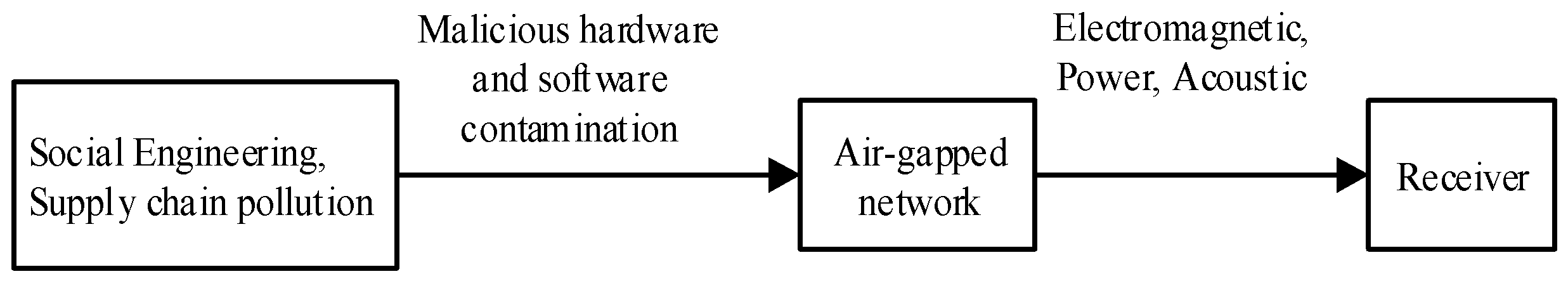
The target host is assumed to be located in a physically isolated network, with no communication with external networks such as the Internet, as shown in
Figure 1. Specific functional software or hardware can be implanted into the target host using social engineering or supply chain pollution. Subsequently, sensitive information can be collected according to the designer’s intention, and covert communication channels can be established with the outside world through media such as electromagnetic waves, power consumption fluctuations, and sound waves. Finally, the receiver obtains sensitive information within the target machine.
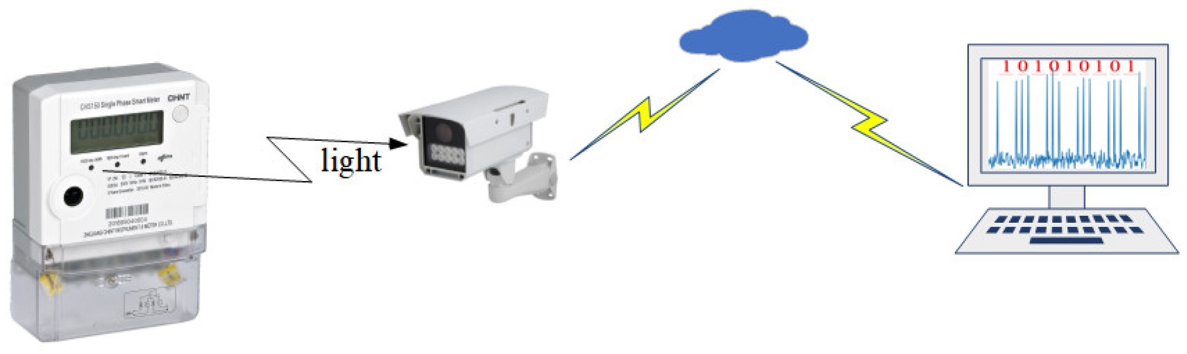
3.2. Bit Sufi-Dance Model
The Bit Sufi-Dance model, similar to other forms of general air gap covert communication, comprises of two distinct components. Firstly, there is the transmitter, also referred to as the meter, which is directly linked to the air gap organization. This transmitter serves as the key element in relaying information across the air gap. Secondly, there is the receiver, which can be either a camera or a smartwatch, depending on the specific setup and needs. This receiver is entirely controlled by the intended recipient of the transmitted data. The entire system, shown in
Figure 2, operates seamlessly to facilitate covert communication across the air gap, ensuring secure and reliable data transfer between the transmitter and the receiver.
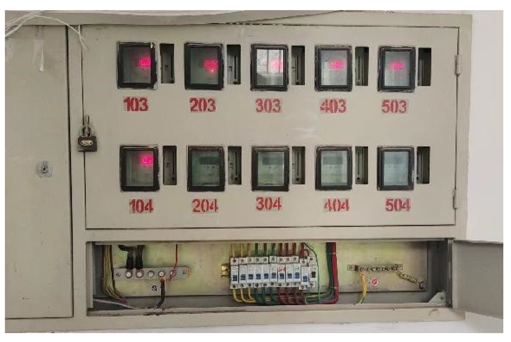
3.2.1. Signal Transmitter
A transmitter is an electricity meter used in air gap isolation equipment, which is a device connected in series on single-phase or three-phase power lines to measure and record the power and energy consumption of equipment, as shown in
Figure 3. First, the computer needs to be infected with specific software or hardware, and then the software collects desired data from the computer (such as credit card numbers, encryption keys, various passwords, documents, etc.). When certain preset conditions are met (such as specific content of interest or a certain time point), data is filtered out through available covert channels. The signal is generated by changing the speed of the mechanical turntable of the meter or altering the flashing frequency of the power indicator LED through oscillation in computer equipment’s power consumption.
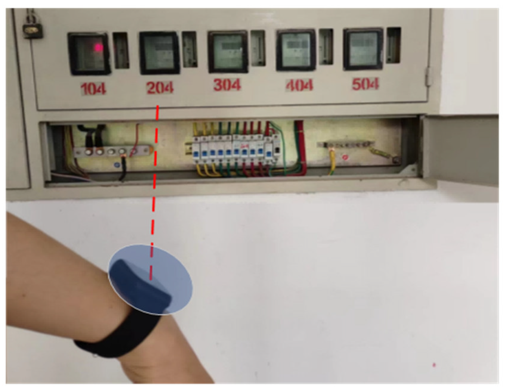
3.2.2. Signal Receiver
A receiver is a line of sight between the light source (electricity meter) and the camera. In this model, there are several types of devices that can be used to receive optical signals from electricity meters, including cameras that communicate with electricity meters, surveillance closed-circuit TVs or IP cameras located outside buildings, etc. Even smartwatches or wearable cameras held by internal personnel (such as smartwatches) can serve as receivers, a situation known as “evil maid” [
17], and the threat scenario is illustrated in
Figure 4. In this article, the method of establishing optical covert channels between electricity meters and optical equipment is studied. Since the data exfiltrated through the electricity meter has been encoded, the receiver first records a video of the meter, and then decodes the video to recover sensitive information.
4. Technical Background
Electricity meters are essential equipment in every household or office, typically located outdoors. The meter’s turntable or LED can display the user’s electricity usage, facilitating potential data exfiltration. The paper examines the technical requirements for data exfiltration through electricity meters.
4.1. Electricity Meter and Power Status
The development history of electricity meters as devices for measuring power consumption can be traced back to the late 19th and early 20th centuries [
18]. Starting from the initial electromechanical measurement based on electromagnetic induction principles, they have evolved into electronic instruments for measurement and currently intelligent measurement. With the application of electronic technology, the accuracy and reliability of electricity meters have been significantly improved.
Electromechanical energy meters have been the most traditional and widely used energy meters for a century. They measure active energy in kWh by calculating the number of revolutions of the conductive metal disk, with its rotational speed being directly proportional to the power passing through it [
19]. When electrical equipment uses electricity, AC current passes through the coil of the meter to generate AC magnetic flux. The alternating magnetic flux then passes through an aluminum sheet, causing vortices on it. These vortices experience force in a magnetic field, resulting in torque (active torque) on the aluminum sheet. Torque is proportional to power consumed by load; higher power and greater torque make aluminum discs rotate faster. Therefore, monitoring the speed of the metal disk makes it possible to monitor power consumption.
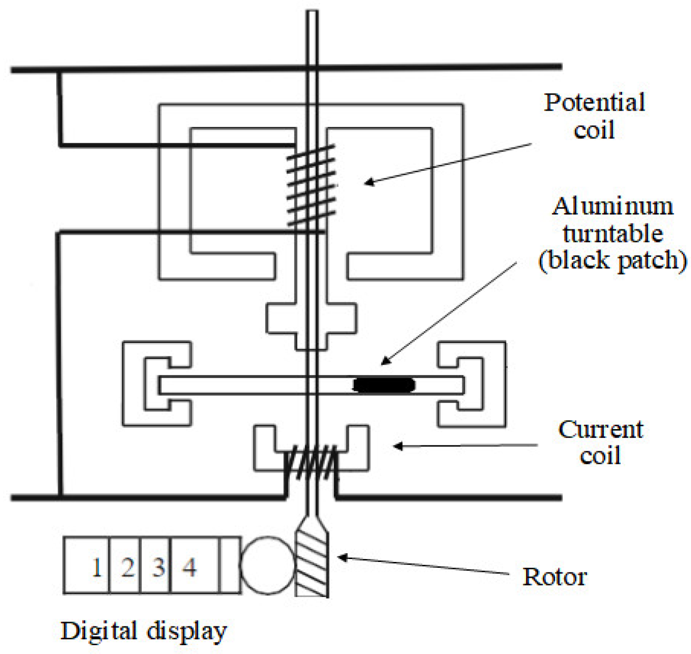
The structure of a typical single-phase electricity meter is shown in
Figure 5 [
20]. Its basic design includes voltage coils, rotors, current coils, aluminum turntables, and digital display modules. However, the moving components of electromechanical systems will vary over time, temperature, and conditions [
21]. External dirt, dust, and humidity can also cause the mechanical gears to wear out, ultimately leading to a decrease in measurement accuracy. Therefore, electromechanical energy meters are gradually being replaced by electronic instrument energy meters.
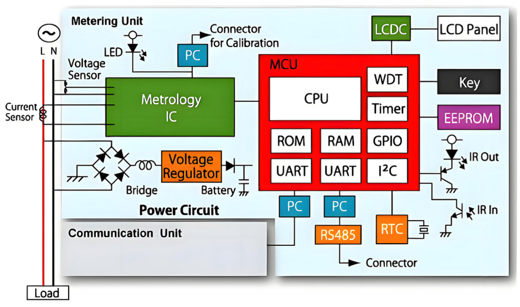
Smart meters are typically based on digital micro technology (DMT), which differentiates them from electronic digital meters due to their additional functions and features. In addition to conventional power measurement and automatic meter reading (AMR), they also enable bidirectional communication between the meter and the base station, allowing for load analysis, prepayment, remote disconnection, and multiple electricity pricing billing. This enhances customer service and ensures a reliable power supply [
22]. The structure is depicted in
Figure 6 [
23]. With the advancement of society and technology, mechanical meters are gradually being replaced by digital and smart meters that offer more powerful functions, convenient usage, and accurate power consumption measurement. The adoption rate in user households and public places has been increasing year by year, and was projected to reach 61% in the UK by the end of 2023 [
24].
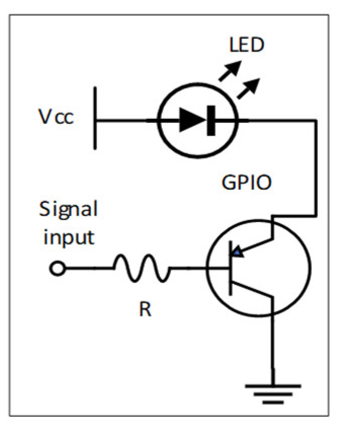
The power status control of a smart meter is achieved through the use of LEDs (Light Emitting Diodes), which are semiconductor light sources that emit light when charges pass through them. LEDs are commonly used as activity indicators in various electronic devices. The wavelength of the emitted light, represented by its color, is determined by the materials used in the semiconductor components of the LEDs. Typically, aluminum gallium indium phosphide (AlGaInP) is utilized for red, orange, and yellow LEDs. In a common smart meter, the indicator light is red. The LED of the device can be controlled by connecting it to the GPIO pin on the device’s PCB (printed circuit board), as shown in
Figure 7.
4.2. Computer Power Consumption
The power consumption of a computer mainly includes the total power consumption of internal hardware, such as the CPU, graphics card, motherboard, sound card, and network card, as well as peripheral devices like keyboards and displays. For desktop computers, the power generally ranges between 120 W and 600 W, while for laptops it is around 40 to 230 W. The power consumption of a computer is primarily determined by its internal hardware components with the CPU and GPU accounting for a significant proportion of energy usage. Mainstream CPUs typically consume approximately 30–250 W [
25] of power, while GPUs can range from tens of watts to 1000 watts in terms of their energy consumption [
26].
However, not all computers are equipped with independent graphics cards; many use integrated display modules instead [
27]. Generally speaking, high-performance multi-core processors tend to have higher power requirements compared to low-end single-core processors which consume relatively less power. Additionally, using resource-intensive software or multitasking can also impact CPU power consumption. The
Figure 8 illustrates a comparison of total power consumption among several computer brands under both low load and high load conditions.
4.3. Camera
Currently, cameras are widely used and ubiquitous in various environments such as television, surveillance, smart homes, smartwatches, and more. In consumer cameras, an imaging tube called a camera was initially used; however, it was later replaced by a new semiconductor known as a charge-coupled device (CCD), and now complementary metal-oxide-semiconductor (CMOS) image sensors are commonly employed. The transition to CCD technology has significantly improved the performance of cameras.
Figure 9 [
28] illustrates the basic block diagram of a camera which consists of an optical unit, image sensor, electronic circuitry, viewfinder, and recording device. The image sensor can be either CMOS or CCD-based while the fundamental camera circuit includes circuits for brightness signal processing, color separation processing, and color signal processing.
4.4. Video Encoding
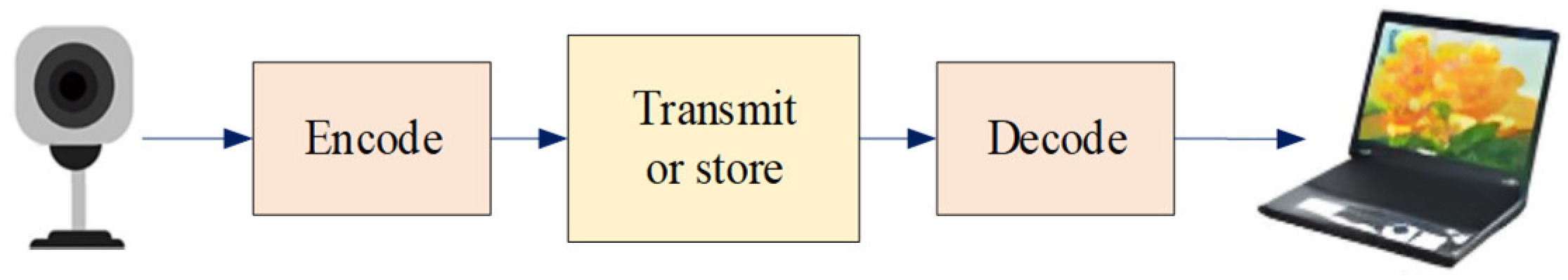
Digital video is composed of frame sequences sampled in both spatial and temporal domains, and direct representation requires a large amount of storage space, necessitating the encoding of video content. Video encoding refers to the process of compressing video content to achieve high transmission and storage efficiency. The most widely used video coding standard currently is H.264 Advanced Video Coding (AVC), which can encode videos into bitstreams for storage and transmission. It has been proposed for 15 years, and so far, most hardware manufacturers support H.264 AVC [
29]. The encoder converts the video to a compressed format, and the decoder restores the compressed video to an uncompressed format. Together, they form the term encoder/decoder, as shown in
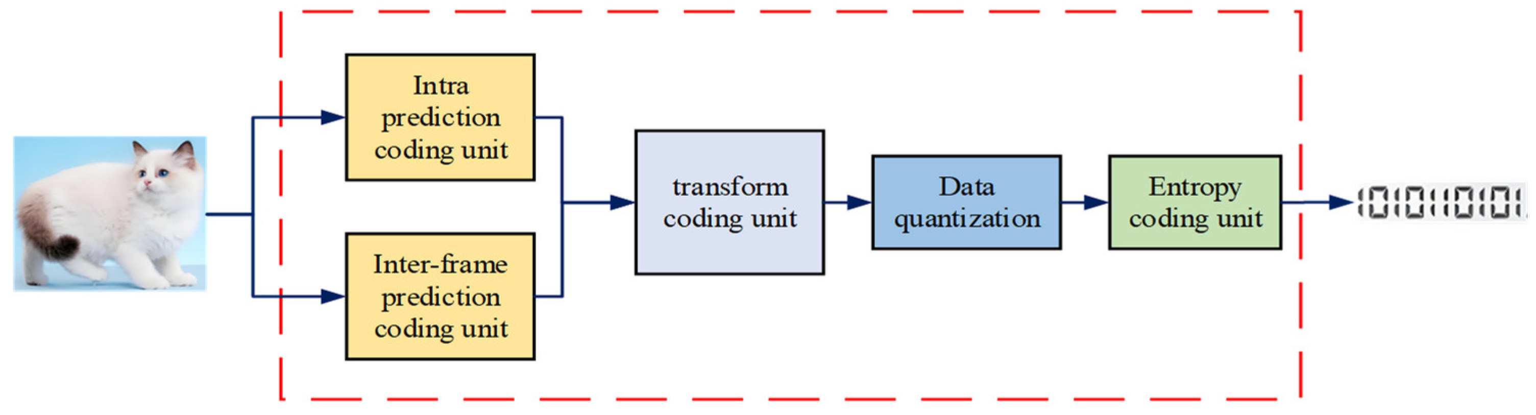
Figure 10 and
Figure 11 illustrates a typical video encoder structure. It consists of four parts: prediction frame encoding unit, transformation encoding unit, data quantization, and entropy encoding unit.
There are generally two methods for video encoding:
4.4.1. Entropy Encoding
A lossless encoding method that compresses video data to the Shannon limit, but due to Shannon limitations, it can only achieve a moderate compression ratio.
4.4.2. Lossy Encoding
Removes redundant and less important information from video data. Lossy compression of videos is usually more effective because the human visual system can tolerate the loss of details.
4.4.3. Video Decoding Library
The FFmpeg [
30] software library can be used to decode videos. It is a cross-platform computer vision and machine learning software library licensed under LGPL or GPL (open source), capable of running on Linux, Windows, Android, and Mac OS operating systems. It integrates functions such as image processing, feature detection and description, video analysis, and image segmentation, making it very convenient for performing video and image processing.
5. Bit Sufi-Dance Communication Technology
In this section, we describe the theoretical and communication aspects of the proposed Bit Sufi-Dance air gap channel, analyze it, and discuss the imaging receiver.
5.1. Mechanical Turntable Transmission
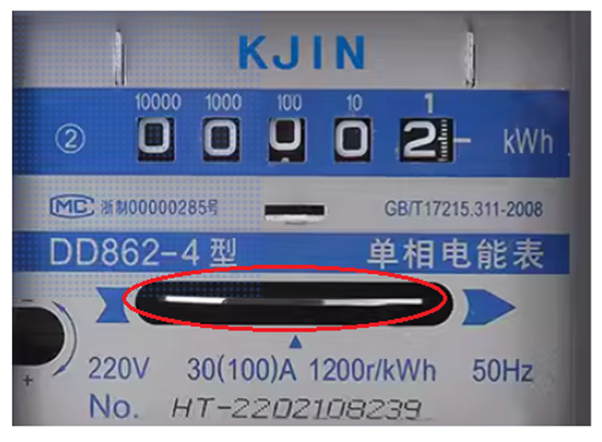
Traditional electricity meters have been widely used since the late 19th century. In most traditional electricity meters, a conductive metal turntable made of copper or aluminum is connected to a mechanical display through a gear mechanism. The energy consumption is measured by calculating the number of revolutions of the conductive metal turntable, with a unit of kWh. The unit of measurement for the induction type electric energy meter with a rotating aluminum turntable is r/kWh, which represents the number of cycles the turntable rotates for every 1 kWh of electrical energy consumed by the appliance.
To enable users to check the normal working condition of the electricity meter, a small area on the outer edge of the conductive metal turntable will be coated with black pigment as a mark, as shown in the
Figure 12. As the turntable rotates, the black color mark will periodically appear, indicating the power consumption of the air gap isolation device through the metal turntable of the electricity meter. This provides a physical foundation for establishing a Bit Sufi-Dance air gap channel for receivers. By utilizing current mature optical speed recognition methods, it is possible to identify and measure the speed (power consumption) of an electricity meter. An optical tachometer is commonly used in industrial settings and enables non-invasive measurement of device speed [
31]. It typically consists of an encoder and parser for continuous speed monitoring and requires optical coupling with rotating axes/components. In this paper, we utilize a camera that can obtain device speed through optical signals, providing a mature technical solution for implementing Bit Sufi-Dance connections.
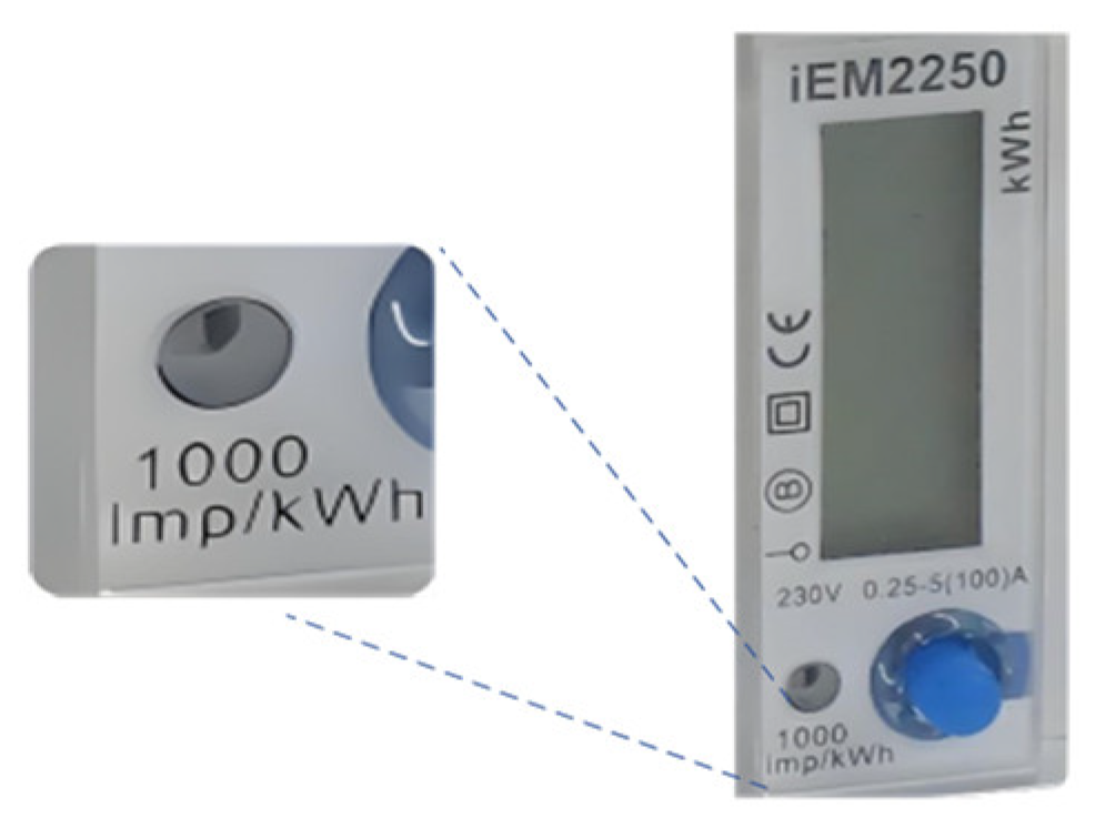
5.2. Flashing LED Transmission
To facilitate users in monitoring power consumption, most electronic and smart meters are equipped with flashing LED that represent the amount of electricity consumed. The LED parameter labeling unit is imp/kWh, which indicates the number of flickering pulses generated by an electrical appliance for every 1 kWh of electricity consumed. Common values for civilian electricity meters are typically 1000, 1600, or 3200 imp/kWh. For instance, Schneider’s renowned electricity meter iME2250 1000 imp/kWh represents every 1000 pulses corresponding to the consumption of 1 kWh of electricity, as shown in
Figure 13.
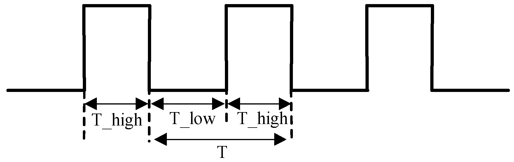
Figure 14 displays a pulse output [
32]. The pulse width, T_high, varies depending on the meter used. T_high remains unchanged during operation. For the iEM2250 m, T_high pulse width is also 90 ms [
33]. The duration between pulses, T_low, varies based on the pulse rate which represents the power measured by the meter.
Calculate power consumption: for the iEM2250 m, each pulse represents 1 Wh of electricity passing through the meter [
32].
Light pulse counting: record the number of flashes of the LED.
When the device within the air gap organization operates a data transmitter (energy consumption modulation software), the frequency of LED flashing in the electricity meter can be influenced by regularly controlling the power consumption of the device, which provides a theoretical and technical basis for researchers.
5.3. Camera Receiver
The camera can serve as a signal receiver for Bit Sufi-Dance. Visual-Based Measurement (VBM) is a concept that replaces on-site measurements by processing sequences of images or video signals captured by cameras to obtain measured values in Engineering Structures [
34]. VBM has been applied in many scenarios, such as item counting, detecting specific shapes or colors, identifying industrial instruments, measuring object movement speed, etc. It is also used in biometric applications for non-contact, non-invasive, and non-destructive detection. The frame rate per second (FPS) is the main factor determining the maximum bit rate of a camera. Common surveillance cameras and mobile watch cameras capture up to 30 frames per second. In our experiment, it is necessary to detect the speed of the mechanical meter turntable or the flashing frequency of the electronic meter LED and then use video processing algorithms to decode all transmissions.
5.3.1. Rotary Speed Detection
The VBM concept was proposed by Ferreira et al. for speed measurement using cameras with mechanical meters [
31]. To measure rotational speed, a new method was introduced to generate actual raw sensor signals for sampling and analysis. A camera was used to capture the change in light reflection intensity of the rotating component as a signal source, followed by counting or frequency domain analysis to infer its rotational speed. In real-time, we selected the region of interest (ROI) from the collected video, which corresponds to the black part of the mechanical meter’s turntable shown in
Figure 12. The received light signal depends on both the camera and meter’s turntable line of sight and visibility. After receiving the recorded video, we processed each frame individually to detect the rotation speed of the turntable.
5.3.2. LED Flashing Detection
A camera can be used to extract LED flicker for electronic and smart meters. After receiving the recorded video, each frame is processed to detect the frequency of LED flicker. Finally, the binary data is decoded based on an encoding scheme.
6. Design and Implementation of Covert Channels
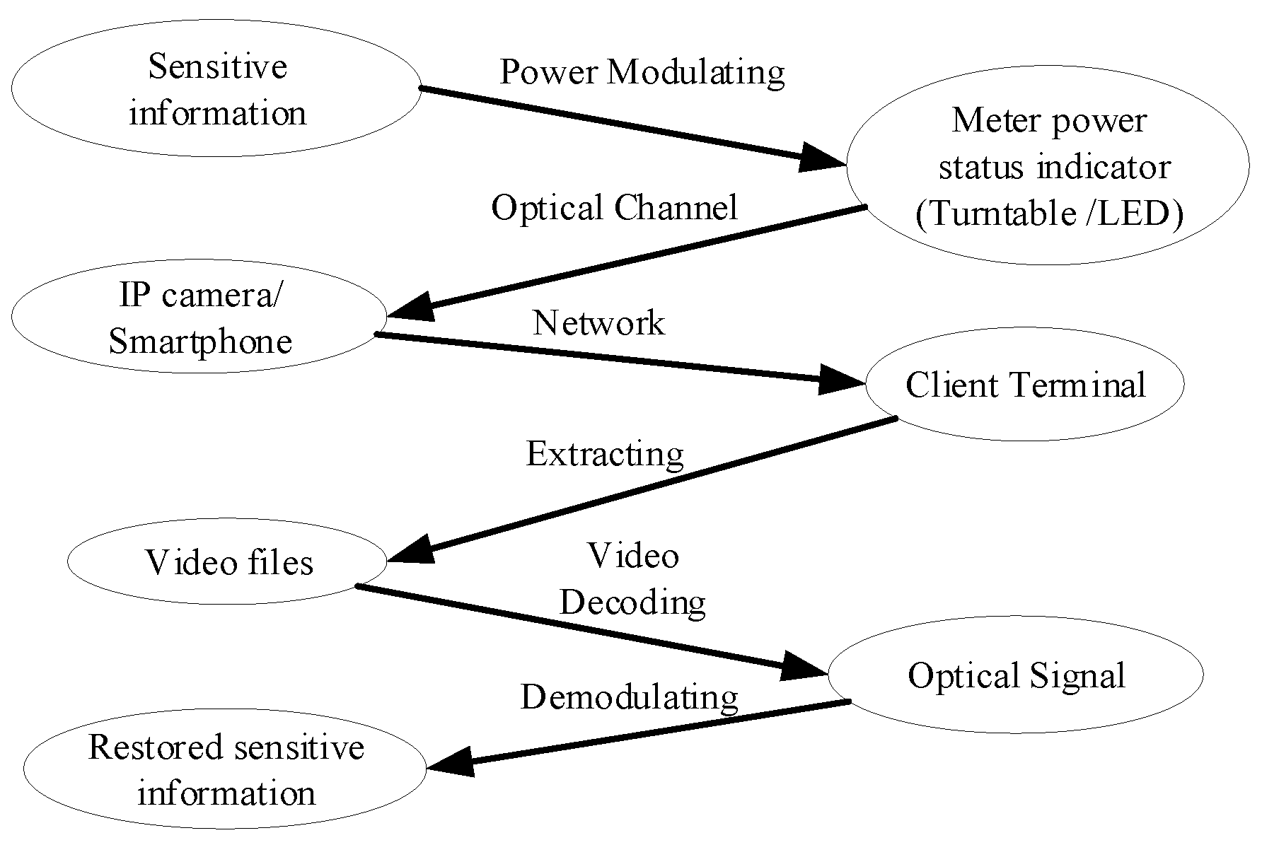
In this section, we introduce data transmission and describe the working principle of the sending software, methods for optical signal generation, data modulation schemes, and data frame structures. We also explore their characteristics and correlation with the model. The workflow of the covert channel is shown in the
Figure 15.
In the model, we assume that two conditions have been met: (1) the computer equipment within the air gap tissue has been installed with a program (sender software) capable of modulating signals and is in an activated state; (2) the electricity meters used by the organization can be captured by cameras. Sensitive information (such as user account, user password, encryption key, key data, etc.) leaks through either the metal turntable or LED indicator light of the electricity meter used by the air gap organization. The light signal from the electricity meter is obtained through surveillance cameras or smartwatch cameras located in public areas, establishing a covert channel between the electricity meter and camera. Subsequently, sensitive data is decoded and restored by extracting signals from video content.
6.1. Software Composition
The software components are shown in
Figure 16. (1) The data collection module collects the data of interest; (2) it encodes the data in the agreed format and divides the encoded data into frames of equal length; (3) error correction codes or checksums are added at the end of each data frame; (4) data frames are sent to the modulator; (5) fluctuations in power consumption from construction equipment directly affect the working status of the meter’s turntable/LED. The core modulation algorithm can be found in Algorithm 1.
| Algorithm 1 Power Modulator |
1. Input: (CPU_Threads, Payload, PayloadSize, bitDuration)
2. binBuff[] = payload
3. i = 0
4. Do
5. if(binBuff[i++] == 1)
6. HighCPUload(bitDuration);
7. else
8. LowCPUload(2 * bitDuration)
9. While (i < payloadSize) |
6.2. Electricity Meter Signal Generation
In our method, the carrier of data is either the metal turntable speed of the meter or the flashing frequency of the LED. To generate signals, we need to control the power consumption of computer equipment, thereby regulating the speed of the metal turntable in mechanical meters or adjusting the LED flashing frequency in electronic meters. It is well known that a computer’s overall power consumption varies with CPU workload, as shown in the
Figure 8. Therefore, software is used to manipulate device power consumption changes, which subsequently impact overall power consumption and ultimately result in regular variations in the metal turntable or LED of the meter.
6.2.1. Metal Turntable
The physical object representing a mechanical electric meter’s metal turntable is shown in
Figure 12. The scene of using a camera to capture the metal turntable of a mechanical electric meter is shown in
Figure 17. As the turntable continues to rotate, black patches will periodically appear in the camera’s field of view, and the light reflectivity of these black patches will be significantly reduced. This change will be recorded by the camera, laying the foundation for subsequent decoding.
6.2.2. LED
Figure 18 depicts the use of a camera to capture the LED on an electricity meter, which reflects the power consumption through its flashing frequency. The camera can continuously capture the complete flashing image of the LED, providing a foundation for subsequent decoding.
6.3. Data Encoding and Signal Modulation
We propose three modulation schemes for exfiltrating meter data: (1) Binary Frequency Shift Keying (2FSK), (2) On/Off Keying (OOK), and (3) Multi-band Amplitude Shift Keying (MASK).
6.3.1. Binary Frequency Shift Keying (2FSK)
FSK modulation is a digital modulation technique that encodes digital information into signals with different frequencies. In the FSK modulation process, a binary “1” or “0” is transmitted through carrier signal frequencies divided into two states. When the digital information is “0”, the frequency of the carrier signal is a fixed center frequency f1; when the digital information is “1”, the frequency of the carrier signal changes to another fixed center frequency f2. Therefore, FSK modulation converts digital information into a series of signals with changing frequencies. In our case, the metal turntable of the mechanical meter represents 0 and 1 at two different speeds, while an electronic meter’s LED indicates 0 and 1 with two different flashing frequencies.
6.3.2. On/Off Keying (OOK)
Switching key control (OOK) is the simplest communication modulation method, which is a simpler form of ASK. When transmitting “0”, there is no carrier signal output; only when transmitting “1” is there a signal output, and the duration of both signals remains the same. In our modulation scheme, when there is no operation by the sending software, the power consumption of the computer device can be reduced to a lower state, representing the transmission of “0”. When the sending software performs high load calculations, it can put the computer device in a high power consumption state, representing the transmission of “1”.
6.3.3. Multi-Band Amplitude Shift Keying (MASK)
Multi-band amplitude shift keying (MASK) utilizes amplitude as a variable, transmitting information bits through the carrier wave’s amplitude. MASK represents the use of signals with multiple amplitudes to convey different bit information. In our study, the sending software can modulate the power consumption of computer devices by implementing four different workloads. This change in power consumption will also synchronously affect the working status of the electricity meter. The 4ASK encoding is shown in
Table 1.
6.4. Data Frame
If the data packet is too long, it will cause synchronization difficulties, error correction difficulties, verification difficulties, and other problems during the communication process. Therefore, we need to standardize the data packet and divide the transmitted data into smaller packets. Each frame consists of a header synchronization code, a payload, and an error correction code. In our scheme, the synchronization code in the header consists of eight alternating bit sequences (‘10101010’). The payload is the actual data we want to transmit, and we arbitrarily choose 64 bits as the payload size. The error correction code is located at the end of each data frame and is used to correct errors in data bits.
7. Evaluation & Analysis
In this section, we evaluate optical covert channels. Our evaluation focuses on the optical characteristics and transmission rate of the meter. In our experiment, we adopted a commonly used method in visible light communication, which assumes that the metal turntable (LED) of the electricity meter and the camera can be directly viewed. The working status of the electricity meter, as shown in the
Figure 19 and
Figure 20.
Figure 21 is shown in the working scenario diagram of the Bit Sufi-Dance covert channel.
7.1. Signal Receiver
The validity of the signals in the video recorded by the camera, showing the electricity meter in operation, depends on the line of sight and visibility during filming. We process the recorded video frame by frame to detect either the metal turntable or LED of the electricity meter. By analyzing each frame, we identify either the speed of the metal turntable or frequency of LED flashing. Finally, we decode binary data based on an OOK encoding scheme.
7.2. Video Processing
The video was decoded using FFmpeg, an open-source computer vision library that offers a comprehensive solution for recording, converting, and streaming audio and video. We have developed a program to receive videos as input and save the active screen of the electricity meter to an output file in order to detect and track the rotation of the metal turntable or LED flashing on the electricity meter.
There are typically two methods for measuring the rotational speed of mechanical electric meters: frequency measurement method and period measurement method. The frequency measurement method is commonly used for high rotational speeds, while the period measurement method is employed for low speeds. Since computer equipment has low power consumption, it results in lower rotational speed of the metal turntable on the electricity meter. Therefore, this article primarily utilizes cycle measurement method for testing purposes.
When capturing video footage of the metal turntable with a camera, there are two distinct areas: a silver area and a black patch area where pixel values change accordingly. Therefore, for each video frame, we select a two-dimensional region on the turntable (x0, y0, x1, y1) as shown in
Figure 22. Each pixel in this image corresponds to a three-dimensional vector value (R, G, B), which allows us to calculate sum of pixels within this selected region using Formula (1).
Continuously recording the difference (P0, P1, P2,... Pn), selecting an appropriate threshold to analyze the cycle of
p-value, can obtain the speed of the metal turntable, the signal waveform is shown in the
Figure 23. The red line in the picture represents the time division of the communication.
Measurement of LED flicker frequency in electronic meters. To detect and quantify LED flicker, we utilized the fundamental methods employed in LED-based communication [
35]. The formula for calculating the pixel intensity values Q, the calculation method can be found in Formula (2). Q for the specified two-dimensional region (x0, y0, x1, y1) of the parsed video frame is as follow, as shown in the
Figure 24.
When continuously recording the value of (Q0, Q1, Q2,... Qn), the brightness of an electric meter LED is the quantified level of light intensity in a two-dimensional image. Due to the constant frame rate (FPS) of the camera sampling, we only need to select the threshold of LED brightness to better identify whether the LED is in a glowing state. By analyzing the periodic variation of Q value, the frequency of LED flashing can be obtained.
In our experiment, we tested various types of cameras as receivers. Using a video processing demodulator to decode all transmissions, the signal waveform is shown in the
Figure 25.
7.3. Data Rate
We used a GIGABYTE AERO 15 laptop for testing, which had a power consumption range of 95–256 W. Then, we measured the communication rate of the Bit Sufi-Dance covert channel using both a mechanical meter with parameters of 1200 r/kWh and an electronic meter with parameters of 1000 imp/kWh. When using mechanical and electronic meters, inconsistent results may occur due to differences in physical accuracy of the products. When the maximum power of the laptop is 256 W, the mechanical meter can reach 101 b/h and the electronic meter can reach 93 b/h. The test results are presented in the
Table 2.
8. Countermeasures
There are three methods for addressing the risk of data leakage caused by establishing a hidden channel between electricity meters and air gap isolation devices.
The first method is to shield the electricity meter of the air gap network from external observation. Blocking the metal turntable signal or LED signal of the electricity meter, which needs to be collected by the receiving end, is crucial for preventing data leakage. However, completely masking the electricity meter requires a significant increase in workload and may hinder users from observing its working status, which is not conducive to its maintenance.
The second method entails monitoring power grid fluctuations in the air gap network, interfering with signals suspected of data leakage, and preventing reception by external sources. When there is excessive noise or interference in the power grid, it submerges any effective signals, thereby safeguarding the security of the air gap network. However, this approach requires additional hardware devices and may lead to increased energy consumption due to interference processes.
The third method involves performing feature recognition on infected computers’ software. This includes identifying software that potentially establishes power gap channels and detecting their behavior through static and dynamic analysis of code. Once such features are detected, operation of the code is terminated. However, since all software utilizes CPU resources and their load is difficult to predict accurately, identifying them based on software behavior can result in a relatively high false alarm rate that interferes with normal user operations.
9. Conclusions
In this paper, we demonstrate how to use the power status indicator (such as a metal turntable or LED) of an electric meter to optically exfiltrate data from a computer with an air gap. By utilizing surveillance cameras and smartwatch cameras to receive status signals from the electricity meter, we provide a detailed technical background at both hardware and software levels. We propose modulation schemes and transmission protocols, address design and implementation issues, and evaluate hidden channels on different types of meters. Our experiments show that when there is a line of sight between the meter and the camera, data can be exfiltrated at a bit rate of 101 bits per hour. The error rate of mechanical meters is 3% and 6.3% respectively. The error rate of electronic meters ranged from 1.6% to 2.4%.
The implications of our findings are significant for the security of air-gapped systems. Our results highlight the vulnerability of physical indicators, such as LEDs, which can be exploited to create covert communication channels. This underscores the need for enhanced physical security measures and the monitoring of environmental signals in sensitive environments. Additionally, our work suggests that organizations should consider the potential risks associated with the deployment of smart devices and cameras, which can inadvertently serve as tools for data exfiltration. To mitigate these risks, we propose three preventive measures.
10. Future Work
In future exploration and practice, we plan to comprehensively deepen the research and application of Bit Sufi-Dance communication solutions. The primary task is to further expand the testing scope, not limited to the currently known electrical equipment, but widely including various new electronic devices and high-power appliances. Through detailed performance testing and data analysis, the maximum communication rate of the Bit Sufi-Dance solution can be accurately evaluated and continuously improved, in order to improve transmission efficiency and increase data transmission speed.
Concurrently, in order to overcome the limitations of communication distance and significantly improve signal quality, we will integrate optical telescope technology into communication systems in the future. This cross-border integration will utilize the excellent focusing and imaging capabilities of optical telescopes as an enhancement tool for camera signal acquisition, which can extend the effective transmission distance of signals. In addition, by finely adjusting the optical system parameters and combining them with advanced signal processing technology, we are expected to significantly reduce the bit error rate during communication, ensure accurate and error free data transmission, and provide technical support for applications in extreme environments such as remote communication.
On this basis, we will continue to explore and introduce more cutting-edge technologies such as machine learning, artificial intelligence, and other auxiliary optimization algorithms to enhance the performance and reliability of Bit Sufi-Dance solutions in multiple dimensions.
In summary, future work will focus on combining technological innovation with practical applications, constantly challenging technological limits, promoting breakthroughs in Bit Sufi-Dance solutions in a wider range of fields, and providing technical and solution references for security researchers.


