Article

Predefined-Time Adaptive Fast Terminal Sliding Mode Control of Aerial Manipulation Based on a Nonlinear Disturbance Observer

The School of Mechanical and Electrical Engineering, Soochow University, Suzhou 215137, China
*
Author to whom correspondence should be addressed.
Electronics 2024, 13(14), 2746; https://doi.org/10.3390/electronics13142746
Submission received: 19 June 2024 / Revised: 11 July 2024 / Accepted: 11 July 2024 / Published: 12 July 2024

Abstract

:
The contribution of this paper is to propose an adaptive fast terminal sliding mode controller that ensures exact predefined time stability of aerial manipulation tracking control based upon the nonlinear disturbance observer.The proposed control strategy is continuous and provides reliability in the situation of model error and nonvanishing disturbance.The adaptive parameter can adapt to the states of a system aimed at increasing the robustness of an aerial manipulator while reducing system chattering. Furthermore, the proposed nonlinear disturbance observer provides a scheme where the estimation of the observer can converge to the actual value within a given predefined time for the sake of enhancing robustness of the aerial manipulation system. Simulation results show the viability of the proposed controller in this paper.

1. Introduction

With the development of science and technology, many countries and organizations carry out research on drones [1,2], which contributes to the development of drone technology. Drones have applications in many fields, including the remote sensing of agricultural products [3], environmental monitoring [4], surface crack detection [5], transmission line inspection [6], border monitoring [7] and so on. With further research, the demand for enhancing the ability of unmanned areal vehicles (UAVs) to interact with the outside world has also increased; a single UAV system can no longer meet all needs. Fortunately, aerial manipulation systems, combining interactivity of manipulator and flexibility of UAVs, are increasingly attracting researchers’ attention in recent years [8,9,10]. The aerial manipulation system combines many advantages; it expands the application scope of robotics and has a broad application prospect. At present, an aerial manipulator system can replace manual work to complete some more dangerous and complex aerial works, such as disengaging high-voltage conductors.
Aerial manipulation platforms have so many advantages, and to effectively control them, it is essential to perform dynamic modeling. Aerial manipulation is under the influence of the coupling effect exerted by its mechanical arm while enhancing its ability to interact with the external environment, and the method of measuring this coupling effect exerted by the mechanical arm is difficult, so its modeling is one research focus. Research methods of modeling aerial manipulation, in general, are classified into two categories; holistic modeling and local modeling. The method of local modeling regards the dynamic interaction of the unmanned aerial vehicle with mechanical arm as part of disturbance. Contrary to that, the method of holistic modeling considers the aerial manipulator as a whole system. For example, Li Ding et al. [11] establishes overall aerial manipulation system modeling by using the Newton–Euler method. Kim et al. [12] applies Euler–Lagrangian method to construct dynamic modeling of an aerial manipulation system equipped with a 3-DOF mechanical arm.
Owing to the diversity of the environment encounted in reality, an aerial manipulation control platform faces disturbances from the outside world during the task, and the value cannot be measured directly by sensors. Therefore, a filter or a disturbance observer is useful to deal with modeling errors and external disturbances. Since the aerial manipulator is a classical nonlinear system, the design of filters or observers for a nonlinear system becomes necessary. In [13,14], Zheng designed a finite-time command filter for a nonlinear system with unmodeled dynamics and external disturbances. In [15], ESO is utilized to estimate the disturbance of aerial manipulation, and the estimation error of ESO is able to be restricted to a certain threshold. In addition, a velocity-based disturbance observer has been constructed in the [16], which increases its robustness to external disturbances and manages accurate full-state estimation.
After estimating the unmodeled dynamics and external disturbances of aerial manipulation, the tracking control of aerial manipulation is a point of focus. Luckily, some advanced controllers designed for nonlinear systems, such as PID and sliding mode control (SMC), can also be applied in aerial manipulation control. In [17,18,19], many improvements have been made to the PID controller. SMC is extensively applied in the realm of nonlinear systems control as a result of its global fast convergence, ease of design and robustness against external disturbances [20,21,22]. Besides the advantages of SMC, SMC also has disadvantages, such as the chattering problem and the convergence problem. To solve the chattering problem, numerous methods have been proposed to mitigate chattering in SMC, such as designing an input saturation function or other similar function to replace the step function [23]. However, this approach may result in the system state reaching a vicinity around the target state, which could introduce steady-state errors [24]. In [25], a fast terminal sliding mode control (FTSMC) for aerial manipulation control is applied to ensure finite-time stability. For the purpose of improving the ability of adapting to the environment and dealing with time-varying disturbance, researchers apply adaptive parameters and design an adaptive fast terminal sliding mode controller (AFTSMC). However, the contributions of AFTSMC mainly focus on finite-time stability, whose convergence time depends on the original state [26].
The aerial manipulation control system, as described in the aforementioned summary, is characterized as a complex, coupled, nonlinear system, and researchers have deeply studied the uncertainty, interference and other factors of the system. However, there are still some issues that have not received widespread attention as far as the author knows:
(1)
The disturbance observer has a certain degree of error, and some error value is related to the initial error, which leads to the selection of the initial value of the general disturbance observer being strict; otherwise, it may not converge.
(2)
The error convergence of the disturbance observer takes time and may not be achieved under the constraint of a predefined time.
(3)
The controller of some systems cannot make the system stable in the predefined time, which means that some sliding mode controllers cannot meet the requirements in some cases with convergence time requirements.
(4)
In sliding mode control, a small coefficient of sign function leads to slow convergence speed, but a large coefficient leads to increased chattering, and the setting of its value needs to be supported by engineering experience.
For the purpose of solving the problems proposed above, this paper designs a predefined time adaptive fast terminal sliding mode controller (PT-AFTSMC) based on a nonlinear disturbance observer. The main contributions of this paper are summarized as follows:
(1)
Compared to conventional nonlinear disturbance observers [15], where the error convergence time is uncertain and dependent on the selection of initial values, we develop a disturbance observer capable of guaranteeing estimation convergence to actual value within the given predefined time.
(2)
In contrast to conventional controllers [27] where the stabilization time is influenced by the system’s initial state or parameters, we design PT-AFTSMC with a predefined time sliding mode surface. When reaching the predefined time sliding mode surface, system slides to equilibrium point within predefined time. This controller ensures that the system stabilizes within the given predefined time, regardless of the initial conditions or system parameters.
(3)
PT-AFTSMC includes an adaptive gain. As it is a quantity that varies with the system state, it cannot only acclerate the convergence of the system, but can also reduce the chattering phenomenon.
The aerial manipulation structure diagram is shown in Figure 1.
Notations: The d i a g ( A ) function retrieves elements of matrix A and constructs a diagonal matrix. The e x p function denotes the exponential function. S ( · ) represents the skew-symmetric matrix. The function s i g n ( · ) represents the symbolic function and the function S a t ( A ) = s i g n ( A ) , | A i | > ν A i ν , | A i | ν , where A i represents the i-th elements of the matrix A. R n represents an n-dimensional vector.

2. Preliminaries

2.1. Kinematic Modeling of an Aerial Manipulation System

Σ E , Σ B , Σ I , respectively, represent manipulator actuator end coordinate system, the UAV’s duselage coordinate system, and the inertial coordinate system. The position and velocity of the UAV’s duselage, respectively, are p b = x y z T and p ˙ b = v x v y v z T , with respect to the inertial coordinate system. The attitude of the UAV’s duselage is described as Φ b = ϕ θ ψ T by extrinsic Euler angles. In order to describe the rate of change in the attitude of Euler angles, we introduce the concept of ω b . ω b represents the absolute angular velocity of the UAV’s duselage in Σ I , which is capable of being calculated by
ω b = T Φ ˙ b .
T is the transformation from Φ ˙ b to ω b . Let ω b b stand for the angle velocity with respect to Σ B . ω b b can be get from
ω b b = R b T ω b = R b T T Φ ˙ b = Q Φ ˙ b .
The transformation from Σ B to Σ I can be fulfilled by ratation matrix R b . n is the number of joints of robotic arm, q i represents the angle between the i-th joint and the XOY plane, and arranges them into a vector:
q = q 1 q 2 q n T .
Assuming that the study of p i b (i = 1 , 2 , 3 , , n ) is conducted within the confines of Σ B and represents the position of each joint. Its coordinate in the Σ I is
p i = p b + R b p i b .
According to [28], in the coordinate system of Σ B , the position p i b and the angular velocity ω i b of each joint have the following relationship
p ˙ i b = J p i q ˙
ω i b = J ω i q ˙ .
q ˙ is the rate of change of the Angle of each joint, which can be obtained by taking the derivative of the angle of the joint q. J p i and J ω i are the Jacobian matrices between the angle velocity rate of the i-th mechanical joint to the velocity and the angular velocity relative to the UAV, respectively.

2.2. Dynamic Modeling of Aerial Manipulation

In this paper, by the method of utilizing the Euler–Lagrange method, we construct the dynamic model of aerial manipulation. Take the generalized coordinate as:
η = p b T Φ b T q T T .
By describing the position and attitude of aerial manipulator, we can determine its kinetic and potential energy. K represents the total kinetic energy of the system. The translational and rotational kinetic energy of the airframe and each joint that constitude the total kinetic energy:
K = K b + i = 1 n K i
where K b stands for the kinetic energy contained in airframe, and i = 1 n K i stands for the kinetic energy contained in each joint. Furthermore, K b is given by:
K b = 1 2 m b p b ˙ T p b ˙ + 1 2 ω b T R b H b R b T ω b
where H b and m b , respectively, are ratational inertia matrix and mass of the airframe. On the other hand, i = 1 n K i is given by:
i = 1 n K i = i = 1 n 1 2 m i p i ˙ T p i ˙ + i = 1 n 1 2 ω i T R b R i b H i R b i R b T ω i
where H i and m i , respectively, are raotational inertia matrix and mass of the i-th mechanical arm joint. R i b is the rotation matrix from the center of i-th of the mechanical arm joint to Σ B . Combined with the (8), (9) and (10), we aer able to rephrase the total kinetic energy as following matrix form:
K = 1 2 η ˙ T M ( η ) η ˙ .
The elements of M ( η ) is given by [29]:
M ( η ) = M 11 M 12 M 13 M 21 M 22 M 23 M 31 M 32 M 33
M 11 = ( m b + i = 1 n m i ) I 3 M 22 = Q T H b Q + i = 1 n ( m i T T S ( R b p i b ) T S ( R b p i b ) T + Q T R i b H i R b i Q ) M 33 = i = 1 n ( m i J P i T J P i + J ω i T R i b H i R b i J ω i ) M 12 = M 21 T = i = 1 n ( m i S ( R b p i b ) T ) M 13 = M 31 T = i = 1 n ( m i R b J P i ) M 23 = M 32 T = i = 1 n ( Q T R i b H i R b i J ω i m i T T S ( R b p i b ) T R b J P i ) .
U represents the total potential energy of aerial manipulator. Similarly, U can be obtained by the following formula:
U = U b + i = 1 n U i ,
where U b stands for the potential energy contained in the UAV and i = 1 n U i stands for the total potential energy contained in each joint. U b and i = 1 n U i can also be obtained by:
U b = m b g e 3 T p b
i = 1 n U i = i = 1 n m i g e 3 T p i ,
where e 3 is a vector in the z direction.
By operating on the Lagrangian, we can derive the equations of motion for the system. L is the Lagrangian operator of the system which can be derived by subtracting potential energy from kinetic energy. The Lagrangian operator can be expressed by:
L = K U .
From [30], the Euler–Lagrangian equation can be expressed by:
d d t L η ˙ L η = u
where u represents generalized input of the system.
Combined with the Euler–Lagrangian equation, we can determine the state-space representation of n-joint aerial manipulation:
M ( η ) η ¨ + C ( η , η ˙ ) η ˙ + G ( η ) = u + f
where u is system input, and f is external disturbance.
Since modeling cannot be completely accurate in practical situations, modeling errors cannot be avoided.
M ( η ) = M 0 ( η ) + Δ M ( η )
C ( η , η ˙ ) = C 0 ( η , η ˙ ) + Δ C ( η , η ˙ )
G ( η ) = G 0 ( η ) + Δ G ( η )
where Δ M ( η ) , Δ C ( η , η ˙ ) , Δ G ( η ) represents the model error of M ( η ) , C ( η , η ˙ ) , G ( η ) , respectively. In combination with Equations (20)–(22), Equation (19) can be rewritten as follows:
M 0 ( η ) η ¨ + C 0 ( η , η ˙ ) η ˙ + G 0 ( η ) = u + f Δ M ( η ) η ¨ Δ C ( η , η ˙ ) η ˙ Δ G ( η ) .
Considering that M 0 ( η ) is a positive definite matrix, it is invertible. Let
δ ( η , η ˙ , η ¨ ) = M 0 1 ( η ) ( f Δ M ( η ) η ¨ Δ C ( η , η ˙ ) η ˙ Δ G ( η ) )
α ( η , η ˙ ) = M 0 1 ( η ) ( C 0 ( η , η ˙ ) η ˙ G 0 ( η ) )
β ( η ) = M 0 1 ( η ) .
Equation (23) can be trasformed into the following form:
η ¨ = α ( η , η ˙ ) + β ( η ) u + δ ( η , η ˙ , η ¨ )

2.3. Predefined-Time Stable System

We employ a typical nonlinear system to investigate the system’s stability time:
x ˙ ( t ) = G ( x ( t ) ) ,
where G ( x ( t ) ) denotes a nonlinear function, G ( 0 ) = 0 , and x R n is a system state. The original condition satisfies x 0 = x ( 0 ) R n .
The time for the system to stabilize is an indicator of the system control, so we introduce the concept of finite time stability and fixed time stability.
Definition 1
([31]). If the system (28) is globally asymptotically stable, it is globally finite-time stable with the condition that the system possesses the ability to reach equilibrium point within a time function T ( x 0 ) . The time function T ( x 0 ) fulfills the requirement that t T ( x 0 ) , x ( t ) = 0 for any initial value x 0 . T ( x 0 ) is named as convergence time function.
Definition 2
([32]). If the system (28) is globally finite-time stable, it is globally fixed-time stable with the condition that the aforementioned convergence time function T ( x 0 ) fulfills the requirement that T m a x , T ( x 0 ) T m a x for any initial value x 0 .
It is worth noting that although under the condition of fixed-time stable system, finding an explicit fixed-time T m a x represented by the system parameters is hard, and in some situations, the fixed-time T m a x cannot be reduced to a fixed constant [33]. This phenomenon prompts us to introduce the concept of predefined time stability.
Definition 3
([34]). If the system (28) is globally fixed-time stable, it is predefined time stable with the condition that, for a given positive constant T c , the aforementioned convergence time function has an upper bound T ( x 0 ) T c . The system (28) is a globally predefined time stable system with the aforementioned condition satisfied.
Next, the method of judging the finite time stability and predefined time stability of the sysem by the Lyapunov function is introduced:
Lemma 1
([35]). Assuming that the positive Lyapunov function of the system satisfies V ˙ + ϑ 1 V + ϑ 2 V γ 0 , t > 0 then V is finite-time stable and the convergence time t s subjects to the following constraints: t s 1 ϑ 1 ( 1 + γ ) ln ϑ 1 V 1 γ ( t 0 ) + ϑ 2 ϑ 2 where ϑ 1 > 0 , ϑ 2 > 0 , 0 < γ < 1 .
Lemma 2
([36]). For a given positive real number T c , if the positive Lyapunov function V ( x ) for the system is bounded above by a function as follows:
V ˙ 1 T c 2 η ( 2 V + V 1 + η 2 + V 1 η 2 ) ,
η 0 , 1 . The system is predefined time stable with the predefined time T c provided that the conditions are satisfied.

2.4. Mathematical Lemmas

We introduce the following mathematical lemmas for the proof of theorem.
Lemma 3
([37]). According to Minkowski inequality, for ι i R and 0 < α < 1 ,
i = 1 n ι i α ( i = 1 n ι i ) α
Lemma 4
([38]). According to Holder inequality, for ς i R and β > 1 ,
i = 1 n ς i β n 1 β ( i = 1 n ς i ) β

3. Design of Predefined Time Nonlinear Disturbance Observer

In this section, a predefined time nonlinear disturbance observer will be designed for the purpose of estimating the value of the total disturbance δ ( η , η ˙ , η ¨ ) to compensate for the effects of the disturbance.
Under a pratical circumstance, the total disturbance δ ( η , η ˙ , η ¨ ) cannot be known in advance. Assume that the the derivative of δ ( η , η ˙ , η ¨ ) is bounded by an upper bound and the above assumption is called the Lipschitz condition.
Theorem 1.
If the total disturbance δ ( η , η ˙ , η ¨ ) satisfies the Lipschitz condition and the disturbance observer has the following form:
z = η ˙ ξ
S = z ˙
ξ ˙ = α ( η , η ˙ ) + β ( η ) u + δ ^ ( η , η ˙ , η ¨ )
δ ^ ˙ ( η , η ˙ , η ¨ ) = ( k + 1 T c 1 · 2 ) S + μ S a t ( S ) + σ S S + 1 T c 1 · 2 ( 2 2 1 S 1 + 2 1 2 · n 2 · S 1 + )
where μ > 0 , k > 0 and = p 1 q 1 < 1 , p 1 is even, q 1 is odd, Δ is the upper bound of δ ^ ˙ ( η , η ˙ , η ¨ ) and σ Δ , the estimation of the disturbance observer will converge to the actual value within any given positive time T c 1 .
Proof of Theorem 1.
The Lipschitz condition can be described by the following inequality:
δ ˙ ( η , η ˙ , η ¨ ) Δ ,
where Δ is a positive real number. According to Equations (32)–(35), the intermediate variables S satisfies the following equation:
S = z ˙ = η ¨ ξ ˙ = α ( η , η ˙ ) + β ( η ) u + δ ( η , η ˙ , η ¨ ) α ( η , η ˙ ) β ( η ) u δ ^ ( η , η ˙ , η ¨ ) = δ ( η , η ˙ , η ¨ ) δ ^ ( η , η ˙ , η ¨ ) .
Taking the derivative of S with respect to time t, we get
S ˙ = δ ˙ ( η , η ˙ , η ¨ ) δ ^ ˙ ( η , η ˙ , η ¨ ) = δ ˙ ( η , η ˙ , η ¨ ) ( k + 1 T c 1 · 2 ) S μ S a t ( S ) σ S S 1 T c 1 · 2 ( 2 2 1 S 1 + 2 1 2 · n 2 · S 1 + ) .
The estimation error matrix E δ is obtained by subtracting matrix δ ^ ( η , η ˙ , η ¨ ) from matrix δ ( η , η ˙ , η ¨ ) , which can be obtained by the following equation:
E δ = δ ( η , η ˙ , η ¨ ) δ ^ ( η , η ˙ , η ¨ ) .
Consider the Lyapunov function with the following form:
V 1 = 1 2 S T S 0 .
Then, the derivative of V 1 is taken:
V ˙ 1 = S T S ˙ = ( k + 1 T c 1 · 2 ) S T S μ S T S a t ( S ) σ S T S S 1 T c 1 · 2 S T ( 2 2 1 S 1 + 2 1 2 · n 2 · S 1 + ) + S T δ ˙ ( η , η ˙ , η ¨ ) .
Considering Lemma 3, we can derive the following inequation:
2 2 1 · S T S 1 = 2 2 1 · i = 1 n S i 2 2 2 1 · ( i = 1 n S i 2 ) 1 2 = 2 2 1 · ( 2 V 1 ) 1 2 = V 1 1 2 .
Similarly, with inequality Lemma 4, the following inequation is given:
2 1 2 · n 2 · S T S 1 + = 2 1 2 · n 2 · i = 1 n S i 2 + 2 1 2 · n 2 · n 2 · ( i = 1 n S i 2 ) 1 + 2 = 2 1 2 · ( 2 V 1 ) 1 + 2 = V 1 1 + 2 .
With the Cauchy inequality, the following condition holds:
σ S T S S + S T δ ˙ ( η , η ˙ , η ¨ ) = σ S + i = 1 n δ ( η , η ˙ , η ¨ ) i S i σ S + δ ( η , η ˙ , η ¨ ) S σ S + Δ S 0 .
Since V 1 0 , the following relationship holds:
( k + 1 T c 1 · 2 ) S T S = 2 k V 1 1 T c 1 · 2 · 2 V 1 1 T c 1 · 2 · 2 V 1 .
Applying the properties of saturation function S a t ( S 3 ) , the following inequality can be given:
S T S a t ( S ) = i = 1 n S i S a t ( S ) i 0 .
According to the Equation (41) to (46), we can conclude that V ˙ 1 satisfies the following inequality:
V ˙ 1 1 T c 1 · 2 · ( 2 V 1 + V 1 1 2 + V 1 1 + 2 ) .
According to Lemma 2, within the predefined time T c 1 , the intermediate state quantity S will stabilize to zero, so the error of the estimation of the disturbance and the actual value of the disturbance will have convergence towards zero. Summarize the above conclusions, the estimation of the disturbance will converge to the actual value of the disturbance within the predefined time T c 1 . □

4. Controller Design

In this section, the AFTSMC and the PT-AFTSMC will be proposed for aerial manipulation tracking control under predefined time conditions.

4.1. Design of ANFTSMC

Theorem 2.
For aerial manipulation system, if the AFTSMC input u A F T S M C is designed as:
ϖ = η η d
S 2 = ϖ ˙ + λ 1 ϖ + λ 2 ϖ m n
u A F T S M C = u 1 + u 2
u 1 = M ( η ) ( α ( η , η ˙ ) + η ¨ d λ 1 ϖ ˙ λ 2 · m n · d i a g ( ϖ m n 1 ) ϖ ˙ δ ^ ( η , η ˙ , η ¨ ) S )
u 2 = M ( η ) ( ρ ( t ) S a t ( S 2 ) c 2 S 2 c 3 S 2 p q )
ρ ˙ ( t ) = D 2 ( t ) ( s i g n ( S 2 ϵ ) 1 ) , ρ ( t ) ρ b D 1 ( t ) ( s i g n ( S 2 ϵ ) + 1 ) + D 2 ( t ) ( s i g n ( S 2 ϵ ) 1 ) , ρ a < ρ ( t ) < ρ b D 1 ( t ) ( s i g n ( S 2 ϵ ) + 1 ) , ρ ( t ) ρ a
D 1 ( t ) = d · ( 1 + 1 e x p ( S 2 ) k 1 )
D 2 ( t ) = d · ( 1 + 1 e x p ( S 2 ) k 2 )
where η d represents the reference signal, p , q , λ 1 and λ 2 are all positive, 1 < m n < 2 and p , q are all odd, m , n are all odd, 0 < p q < 1 , then the system is finite-time stable and finite time t s 1 satisfies the following inequality:
t s 1 1 2 c 2 ( 1 + p + q 2 q ) ln 2 c 2 V 1 p + q 2 q ( 0 ) + 2 p + q 2 q c 3 2 p + q 2 q c 3 .
Proof of Theorem 2.
Upon differentating, we get:
S ˙ 2 = ϖ ¨ + λ 1 ϖ ˙ + λ 2 · m n · d i a g ( ϖ m n 1 ) ϖ ˙ = η ¨ η ¨ d + λ 1 ϖ ˙ + λ 2 · m n · d i a g ( ϖ m n 1 ) ϖ ˙ = α ( η , η ˙ ) + β ( η ) u A F T S M C + δ ( η , η ˙ , η ¨ ) η ¨ d + λ 1 ϖ ˙ + λ 2 · m n · d i a g ( ϖ m n 1 ) ϖ ˙ .
Spliting the system input into the sum of two parts is to distinguish the role of the two inputs, where u 1 is called counteract input and u 2 is called reaching law input. The counteract input u 1 is given by: According to [27], the traditional reaching law input u 2 is designed by:
u 2 F T S M C = M ( η ) ( c 1 s i g n ( S 2 ) c 2 S 2 c 3 S 2 p q ) .
For reducing the time of system convergence when the disturbance is big and decreasing the chattering of sliding mode control when the disturbance is small, we design an adaptative parameter ρ ( t ) that can adapt the system change to replace the constant c 1 . At the same time, the function of s i g n ( S 2 ) may generate chattering in the manipulation system. Hence, Equation (58) is rewritten as:
u 2 = M ( η ) ( ρ ( t ) S a t ( S 2 ) c 2 S 2 c 3 S 2 p q )
where S a t represents the saturation function.
Considering the Equations (51), (52) and (57), the derivative of S 2 is given as:
S ˙ 2 = ρ ( t ) S a t ( S 2 ) c 2 S 2 c 3 S 2 p q .
The Lyapunov function is given as follows:
V 2 = 1 2 S 2 T S 2 .
Then, the derivative of V 2 is taken:
V ˙ 2 = S 2 T S ˙ 2 = ρ ( t ) S 2 T S a t ( S 2 ) c 2 S 2 T S 2 c 3 S T S 2 p q = ρ ( t ) i = 1 n S 2 i S a t ( S 2 ) i 2 c 2 V 2 c 3 i = 1 n | S 2 i | 1 + p q .
Apply the properties of function S a t ( S 2 ) ,
i = 1 n S 2 i S a t ( S 2 ) i 0 .
According to Lemma 2, we can obtain:
i = 1 n | S 2 i | 1 + p q ( i = 1 n S 2 i 2 ) p + q 2 q = ( 2 V 2 ) p + q 2 q .
According to Equations (60)–(62), the following inequality is given:
V ˙ 2 2 c 2 V 2 2 p + q 2 q c 3 V 2 p + q 2 q .
With Lemma 1, the system is finite-time stable and the finite time t s 1 satisfies
t s 1 1 2 c 2 ( 1 + p + q 2 q ) ln 2 c 2 V 1 p + q 2 q ( 0 ) + 2 p + q 2 q c 3 2 p + q 2 q c 3 .

4.2. Design of PT-AFTSMC

Considering the convergence time of a finite-time stable system is exposed to the effect of the original value of the Lyapunov function, we design a PT-AFTSMC which means the convergence time is always less than the given value.
Theorem 3.
For aerial manipulation system, if the PT-AFTSMC input u P T A F T S M C is designed as:
S 3 = ϖ ˙ + ( 2 m 2 2 n 2 1 · ϖ 1 m 2 n 2 + 2 1 m 2 2 n 2 · n m 2 2 n 2 · ϖ 1 + m 2 n 2 ) · π n 2 m 2 T c 3
u P T A F T S M C = u 3 + u 4
u 3 = M ( η ) ( α ( η , η ˙ ) + η ¨ d 2 m 2 2 n 2 1 · π n 2 m 2 T c 3 · ( 1 m 2 n 2 ) · d i a g ( ϖ m 2 n 2 ) · ϖ ˙ 2 1 m 2 2 n 2 · π n 2 m 2 T c 3 · n m 2 2 n 2 · ( 1 + m 2 n 2 ) · d i a g ( ϖ m 2 n 2 ) · ϖ ˙ δ ^ ( η , η ˙ , η ¨ ) S )
u 4 = M ( η ) ( ρ ( t ) S a t ( S 3 ) ( ν + 1 T c 2 · 2 χ ) S 3 1 T c 2 · 2 χ ( 2 χ 2 1 · S 3 1 χ + 2 1 χ 2 · n χ 2 · S 3 1 + χ ) )
ρ ˙ ( t ) = D 2 ( t ) ( s i g n ( S 3 ϵ ) 1 ) , ρ ( t ) ρ b D 1 ( t ) ( s i g n ( S 3 ϵ ) + 1 ) + D 2 ( t ) ( s i g n ( S 3 ϵ ) 1 ) , ρ a < ρ ( t ) < ρ b D 1 ( t ) ( s i g n ( S 3 ϵ ) + 1 ) , ρ ( t ) ρ a
D 1 ( t ) = d · ( 1 + 1 e x p ( S 3 ) k 1 )
D 2 ( t ) = d · ( 1 + 1 e x p ( S 3 ) k 2 )
where ρ ( t ) is designed to be the same as AFTSMC, m 2 , n 2 , p 2 and q 2 are all positive, 0 < m 2 n 2 < 1 and m 2 is even, n 2 is odd, 0 < χ = p 2 q 2 < 1 , p 2 is even, q 2 is odd, then the aerial manipulation system is predefined time stable with predefined time T c 2 + T c 3 .
Proof of Theorem 3.
Take the derivative of S 3 with respect to time t,
S ˙ 3 = ϖ ¨ + 2 m 2 2 n 2 1 · π n 2 m 2 T c 3 · ( 1 m 2 n 2 ) · d i a g ( ϖ m 2 n 2 ) · ϖ ˙ + 2 1 m 2 2 n 2 · π n 2 m 2 T c 3 · n m 2 2 n 2 · ( 1 + m 2 n 2 ) · d i a g ( ϖ m 2 n 2 ) · ϖ ˙ .
Take (67)−(70) into (74),
S ˙ 3 = ρ ( t ) S a t ( S 3 ) ( ν + 1 T c 2 · 2 χ ) S 3 1 T c 2 · 2 χ ( 2 χ 2 1 S 3 1 χ + 2 1 χ 2 · n χ 2 · S 3 1 + χ ) .
We design the Lyapunov function as follows:
V 3 = 1 2 S 3 T S 3 .
Then, we get the following equation by taking the derivative of the Lyapunov function V 3 :
V ˙ 3 = ρ ( t ) S 3 T S a t ( S 3 ) ( ν + 1 T c 2 · 2 χ ) S 3 T S 3 1 T c 2 · 2 χ ( 2 χ 2 1 S 3 T S 3 1 χ + 2 1 χ 2 · n χ 2 · S 3 T S 3 1 + χ ) .
Applying the properties of saturation function S a t ( S 3 ) , the following inequality can be given:
S 3 T S a t ( S 3 ) = i = 1 n S 3 i S a t ( S 3 ) i 0 .
Since the function V 3 is a positive definite function,
( ν + 2 T c 2 · χ ) S 3 T S 3 = 2 ν V 3 + 2 T c 2 · χ · ( 2 V 3 ) 2 T c 2 · χ · ( 2 V 3 ) .
Considering Lemma 3, we can derive the following inequation:
2 χ 2 1 · S 3 T · S 3 1 χ = 2 χ 2 1 · i = 1 n S 3 i 2 χ 2 χ 2 1 · ( i = 1 n S 3 i 2 ) 1 χ 2 = 2 χ 2 1 · ( 2 V 3 ) 1 χ 2 = V 3 1 χ 2 .
Similarly, with inequality Lemma 4, the following inequation is given:
2 1 χ 2 · n χ 2 · S 3 T S 3 1 + χ = 2 1 χ 2 · n χ 2 · i = 1 n S 3 i 2 + χ 2 1 χ 2 · n χ 2 · n χ 2 · ( i = 1 n S 3 i 2 ) 1 + χ 2 = 2 1 χ 2 · ( 2 V 3 ) 1 + χ 2 = V 3 1 + χ 2 .
According to the Equation (71) to (75), we can conclude that V ˙ 3 satisfies the following inequality:
V ˙ 3 1 T c 2 · 2 χ · ( 2 V 3 + V 3 1 χ 2 + V 3 1 + χ 2 ) .
According to Lemma 2, the variable S 3 is predefined time stable with predefined time T c 2 . After T c 2 , the variable S 3 equals zero, and take the the Lyapunov function V 4
V 4 = 1 2 ϖ T ϖ .
Since S 3 equals zero, the following formula holds:
ϖ ˙ = ( 2 m 2 2 n 2 1 · ϖ 1 m 2 n 2 + 2 1 m 2 2 n 2 · n m 2 2 n 2 · ϖ 1 + m 2 n 2 ) · π n 2 m 2 T c 3 .
The derivative of V 4 is obtained by:
V ˙ 4 = ϖ T ϖ ˙ = ( 2 m 2 2 n 2 1 · ϖ T ϖ 1 m 2 n 2 + 2 1 m 2 2 n 2 · n m 2 2 n 2 · ϖ T ϖ 1 + m 2 n 2 ) · π n 2 m 2 T c 3
Considering Lemma 3, we get the inequality:
2 m 2 2 n 2 1 · ϖ T ϖ 1 m 2 n 2 = 2 m 2 2 n 2 1 · i = 1 n | ϖ i | 2 m 2 n 2 2 m 2 2 n 2 1 · ( i = 1 n ϖ i 2 ) 1 m 2 2 n 2 = 2 m 2 2 n 2 1 · ( 2 V 4 ) 1 m 2 2 n 2 = V 4 1 m 2 2 n 2 .
Considering Lemma 4, we get the inequality:
2 1 m 2 2 n 2 · n m 2 2 n 2 · ϖ T ϖ 1 + m 2 n 2 = 2 1 m 2 2 n 2 · n m 2 2 n 2 · i = 1 n | ϖ i | 2 + m 2 n 2 2 1 m 2 2 n 2 · n m 2 2 n 2 · n m 2 2 n 2 i = 1 n ( ϖ i 2 ) 1 + m 2 2 n 2 = 2 1 m 2 2 n 2 · ( 2 V 4 ) 1 + m 2 2 n 2 = V 4 1 + m 2 2 n 2 .
Take (83) and (84) into (82),
V ˙ 4 ( V 4 1 m 2 2 n 2 + V 4 1 + m 2 2 n 2 ) · π n 2 m 2 T c 3 .
Evaluate the definite integral with time,
2 T c 3 π V 4 ( T c 2 ) 0 m 2 2 n 2 d V 4 V 4 1 m 2 2 n 2 + V 4 1 + m 2 2 n 2 T c 2 t d t .
Then, we get:
t T c 2 + 2 T c 3 π 0 V 4 ( T c 2 ) m 2 2 n 2 d V 4 V 4 1 m 2 2 n 2 + V 4 1 + m 2 2 n 2 = T c 2 + T c 3 · 2 π a r c t a n ( V 4 m 2 2 n 2 ( T c 2 ) ) T c 2 + T c 3 .
In summary, the convergence time of aerial manipulation control is less than T c 2 + T c 3 . □

5. Simulation Results

In this section, the effectiveness and reliability of the aerial manipulation control algorithm with two joints model will be verified in Matlab R2022a. Table 1 gives the physical parameters for the simulation of aerial manipulation.
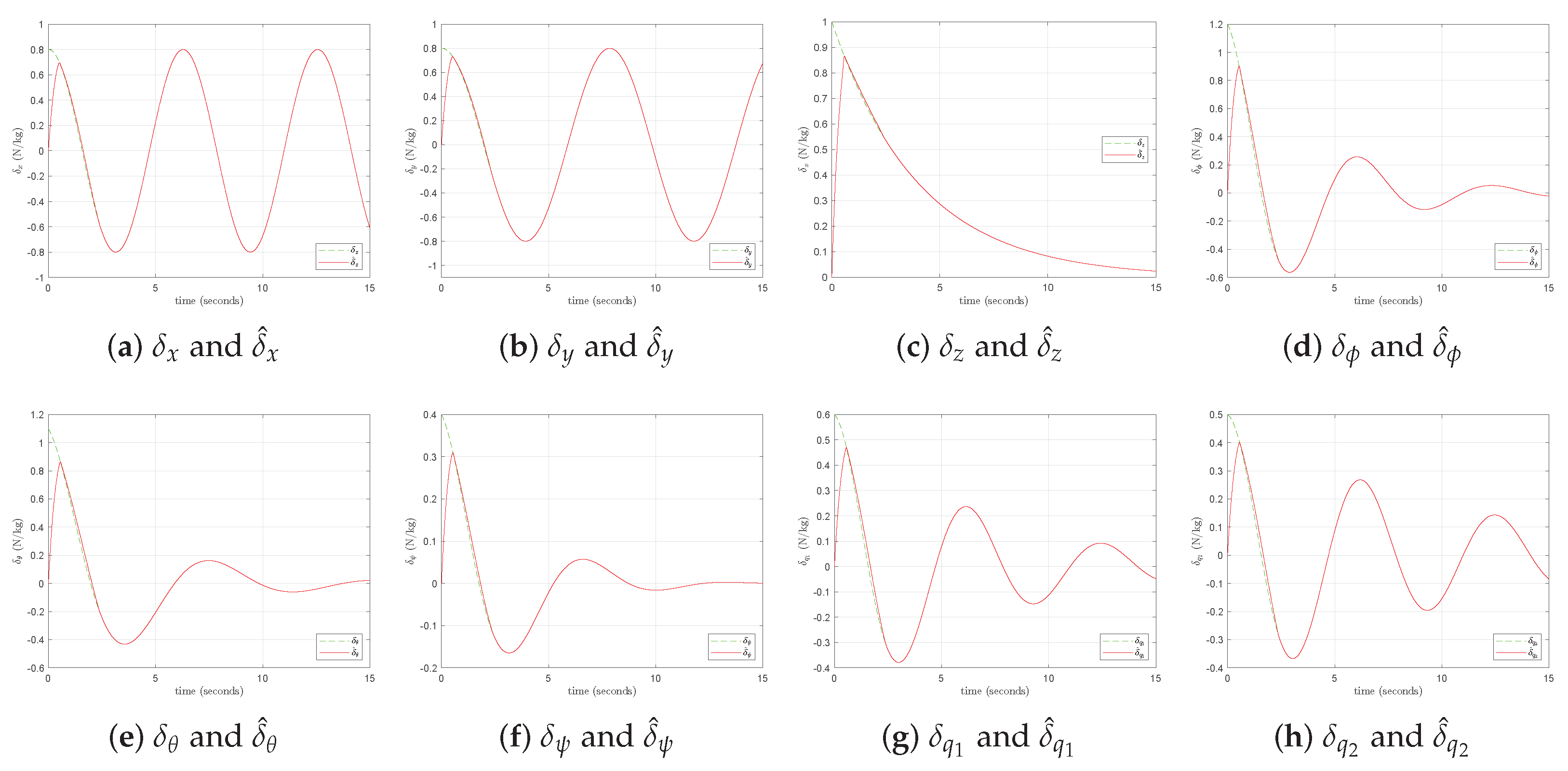
Set the total disturbance δ ( η , η ˙ , η ¨ ) = 0.8 c o s ( 0.3 t ) 0.8 c o s ( 0.25 t ) e x p ( 0.25 t ) 1.2 c o s ( 0.5 t ) e x p ( 0.25 t ) 1.1 c o s ( t ) e x p ( 0.25 t ) 0.2 ( c o s ( 0.5 t ) + c o s ( t ) ) e x p ( 0.25 t ) 0.6 c o s ( t ) e x p ( 0.15 t ) 0.5 c o s ( t ) e x p ( 0.1 t ) T . The parameters of aerial manipulation system disturbance observer are T c 1 = 8 , α = 2 3 , μ = 1 , σ = 2 and k = 0.4 . Let the reference signal η d = 20 c o s ( t ) 20 s i n ( t ) 25 π 3 π 6 π 12 π 2 π 3 T . The Figure 2 is the simulation result of the disturbance observer proposed in this paper.
It can be seen from the Figure 2 that the error of the actual and estimation of the total disturbance will converge to zero in predefined time T c 1 . In addition, the original values of the disturbance are all set to zero. This demonstrates that the disturbance observer does not rely too much on the selection of initial values and has strong robustness.
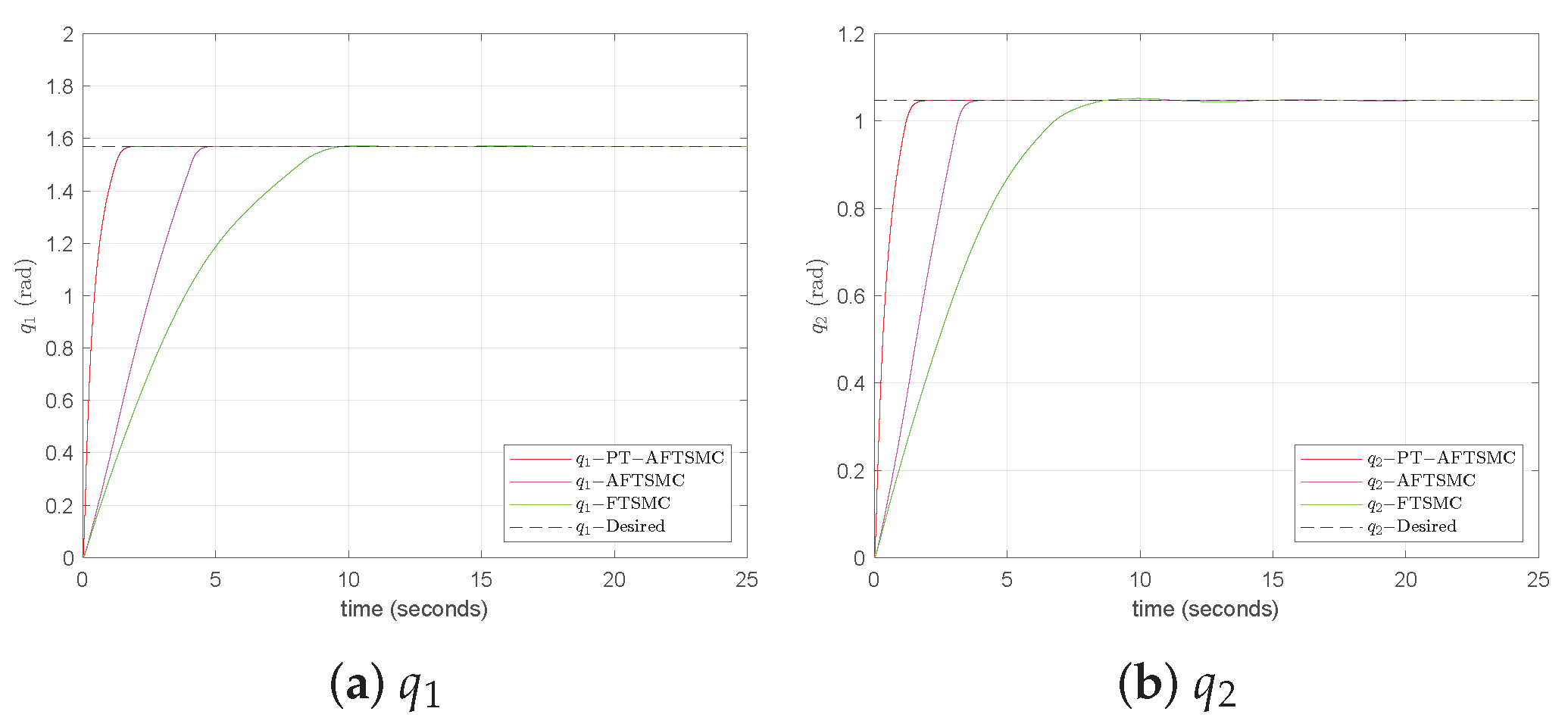
We design the parameters of controller as T c 2 = 8 , T c 3 = 2 , λ 1 = 10 , λ 2 = 8 , m = 5 , n = 3 , m 2 = 2 , n 2 = 3 , p 1 = p 2 = 2 , q 1 = q 2 = 3 , p = 1 , q = 3 , μ = 0.4 , c 1 = 1 , c 2 = 0.2 and c 3 = 0.2 . The parameters of adaptative law are ρ ( 0 ) = 1 , ρ a = 0.5 , ρ b = 5 , d = 1 , k 1 = 2 , k 2 = 4 and ϵ = 2.5 . The following figs are the simulation result of the controllers proposed in this paper.
The Figure 3, Figure 4 and Figure 5 demonstrate that the predefined time controller of the aerial manipulation is completed within the predefined time T c 2 . By comparing the predefined time AFTSMC and AFTSMC, conclusions can be drawn that the PT-ANFTSMC can be stable within the predefined time T c 2 while the convergence time of AFTSMC is subjected to the influence of the parameters and the initial value of the system. In the above Figure, the FTSMC generates lager chattering than the predefined time AFTSMC and AFTSMC when the disturbance is small. Moreover, the AFTSMC can reach the reference value faster than FTSMC, which shows greater robustness. In conclusion, the predefined time AFTSMC can be stable within the predefined time T c 2 + T c 3 and the adaptative parameter can strengthen the robustness when the disturbance is distant from the interval of equilibrium point and reduce the chattering phenomenon when the disturbance is in the interval of the equilibrium point.

6. Conclusions

In this paper, a normal AFTSMC and a predefined time-stable AFTSMC for the tracking control of position, attitude and mechanical arm joint angle of aerial manipulator based on the predefined time nonlinear disturbance observer are presented. Compared with traditional FTSMC, the adaptative parameter designed in this paper will not only accelerate convergence into the interval and improve the robustness of the controller when the state point is distant from the interval of equilibrium point, but also obtains a small chattering phenomenon when the state point is in the interval. The PT−AFTSMC is able to reach an equilibrium point within the predefined time, not constrained by the parameters and the initial values of the system. Future work will involve the study of robust control for jump aerial manipulation system control whose space representation undergoes transitions when interacting with the external environment.

Author Contributions

Conceptualization, M.Z.; Methodology, M.Z.; Software, M.Z.; Validation, M.Z. and H.Q.; Resources, Y.Z.; Writing—original draft, M.Z.; Writing—review and editing, Y.Z. All authors have read and agreed to the published version of the manuscript.

Funding

This research received no external funding.

Data Availability Statement

Data are contained within the article.

Conflicts of Interest

The authors declare no conflict of interest.

References

  1. Labbadi, M.; Cherkaoui, M. Robust adaptive backstepping fast terminal sliding mode controller for uncertain quadrotor UAV. Aerosp. Sci. Technol. 2019, 93, 105306. [Google Scholar] [CrossRef]
  2. Zheng, X.; Yu, X.; Yang, X.; Zheng, W.X. Adaptive NN Zeta-Backstepping Control with Its Application to a Quadrotor Hover. IEEE Trans. Circuits Syst. Express Briefs 2024, 71, 747–751. [Google Scholar] [CrossRef]
  3. Faiçal, B.S.; Costa, F.G.; Pessin, G.; Ueyama, J.; Freitas, H.; Colombo, A.; Fini, P.H.; Villas, L.; Osório, F.S.; Vargas, P.A.; et al. The use of unmanned aerial vehicles and wireless sensor networks for spraying pesticides. J. Syst. Archit. 2014, 60, 393–404. [Google Scholar] [CrossRef]
  4. Zhang, M.; Li, X. Drone-Enabled Internet-of-Things Relay for Environmental Monitoring in Remote Areas without Public Networks. IEEE Internet Things J. 2020, 7, 7648–7662. [Google Scholar] [CrossRef]
  5. Zhu, Q.; Dinh, T.H.; Phung, M.D.; Ha, Q.P. Hierarchical Convolutional Neural Network with Feature Preservation and Autotuned Thresholding for Crack Detection. IEEE Access 2021, 9, 60201–60214. [Google Scholar] [CrossRef]
  6. Wang, W.; Shen, Z.; Zhou, Z. A Novel Vision- and Radar-Based Line Tracking Assistance System for Drone Transmission Line Inspection. Remote Sens. 2024, 16, 355. [Google Scholar] [CrossRef]
  7. Ahmadian, N.; Lim, G.J.; Torabbeigi, M.; Kim, S.J. Smart border patrol using drones and wireless charging system under budget limitation. Comput. Ind. Eng. 2022, 164, 107891. [Google Scholar] [CrossRef]
  8. Liu, J.; Zhang, D.; Chen, Y.; Xia, Z.; Wu, C. Design of a class of generalized parallel mechanisms for adaptive landing and aerial manipulation. Mech. Mach. Theory 2022, 170, 104692. [Google Scholar] [CrossRef]
  9. Samadikhoshkho, Z.; Ghorbani, S.; Janabi-Sharifi, F. Vision-based reduced-order adaptive control of aerial continuum manipulation systems. Aerosp. Sci. Technol. 2022, 121, 107322. [Google Scholar] [CrossRef]
  10. Emami, S.A.; Banazadeh, A. Simultaneous trajectory tracking and aerial manipulation using a multi-stage model predictive control. Aerosp. Sci. Technol. 2021, 112, 106573. [Google Scholar] [CrossRef]
  11. Ding, L.; Zhu, G.; Li, Y.; Wang, Y. Cable-Driven Unmanned Aerial Manipulator Systems for Water Sampling: Design, Modeling, and Control. Drones 2023, 7, 450. [Google Scholar] [CrossRef]
  12. Kim, S.; Choi, S.; Kim, H.J. Aerial manipulation using a quadrotor with a two DOF robotic arm. In Proceedings of the 2013 IEEE/RSJ International Conference on Intelligent Robots and Systems, Tokyo, Japan, 3–7 November 2013; pp. 4990–4995. [Google Scholar] [CrossRef]
  13. Zheng, X.; Yu, X.; Yang, X.; Rodriguez-Andina, J.J. Practical Finite-Time Command-Filtered Adaptive Backstepping with Its Applications to Quadrotor Hovers. IEEE Trans. Cybern. 2024, 54, 3017–3029. [Google Scholar] [CrossRef] [PubMed]
  14. Zheng, X.; Yu, X.; Jiang, J.; Yang, X. Practical Finite-Time Command Filtered Backstepping with its Application to DC Motor Control Systems. IEEE Trans. Ind. Electron. 2024, 71, 2955–2964. [Google Scholar] [CrossRef]
  15. Cao, H.; Li, Y.; Liu, C.; Zhao, S. ESO-Based Robust and High-Precision Tracking Control for Aerial Manipulation. IEEE Trans. Autom. Sci. Eng. 2024, 21, 2139–2155. [Google Scholar] [CrossRef]
  16. Hocaoglu, Y.; Mumcuoglu, M.E.; Unel, M. Disturbance Observer Based Fault Tolerant Control of a Quadrotor Helicopter. In Proceedings of the IECON 2021—47th Annual Conference of the IEEE Industrial Electronics Society, Toronto, ON, Canada, 13–16 October 2021; pp. 1–6. [Google Scholar] [CrossRef]
  17. Pounds, P.E.I.; Dollar, A.M. Stability of Helicopters in Compliant Contact Under PD-PID Control. IEEE Trans. Robot. 2014, 30, 1472–1486. [Google Scholar] [CrossRef]
  18. Kutia, J.R.; Stol, K.A.; Xu, W. Aerial Manipulator Interactions with Trees for Canopy Sampling. IEEE-ASME Trans. Mechatron. 2018, 23, 1740–1749. [Google Scholar] [CrossRef]
  19. Hua, H.; Fang, Y.; Zhang, X.; Qian, C. Auto-tuning nonlinear PID-type controller for rotorcraft-based aggressive transportation. Mech. Syst. Signal Process. 2020, 145, 106858. [Google Scholar] [CrossRef]
  20. Erbatur, K.; Kaynak, M.; Sabanovic, A. A study on robustness property of sliding-mode controllers: A novel design and experimental investigations. IEEE Trans. Ind. Electron. 1999, 46, 1012–1018. [Google Scholar] [CrossRef]
  21. Šabanovic, A. Variable Structure Systems with Sliding Modes in Motion Control—A Survey. IEEE Trans. Ind. Inform. 2011, 7, 212–223. [Google Scholar] [CrossRef]
  22. Herman, P. Model Simplification for Asymmetric Marine Vehicles in Horizontal Motion-Verification of Selected Tracking Control Algorithms. Electronics 2024, 13, 1820. [Google Scholar] [CrossRef]
  23. Utkin, V.I. Sliding Modes in Control and Optimization; Communications and Control Engineering Series; Springer: Berlin/Heidelberg, Germany, 1992. [Google Scholar]
  24. Feng, Y.; Han, F.; Yu, X. Chattering free full-order sliding-mode control. Automatica 2014, 50, 1310–1314. [Google Scholar] [CrossRef]
  25. Fang, Q.; Mao, P.; Shen, L.; Wang, J. A global fast terminal sliding mode control for trajectory tracking of unmanned aerial manipulation. Meas. Control 2023, 56, 763–776. [Google Scholar] [CrossRef]
  26. Chen, Y.; Liang, J.; Wu, Y.; Miao, Z.; Zhang, H.; Wang, Y. Adaptive Sliding-Mode Disturbance Observer-Based Finite-Time Control for Unmanned Aerial Manipulator with Prescribed Performance. IEEE Trans. Cybern. 2023, 53, 3263–3276. [Google Scholar] [CrossRef]
  27. Liu, H.; Zhang, T. Neural network-based robust finite-time control for robotic manipulators considering actuator dynamics. Robot. Comput.-Integr. Manuf. 2013, 29, 301–308. [Google Scholar] [CrossRef]
  28. Bonyan Khamseh, H.; Ghorbani, S.; Janabi-Sharifi, F. Unscented Kalman filter state estimation for manipulating unmanned aerial vehicles. Aerosp. Sci. Technol. 2019, 92, 446–463. [Google Scholar] [CrossRef]
  29. Xu, W.; Cao, L.; Peng, B.; Wang, L.; Gen, C.; Liu, Y. Adaptive Nonsingular Fast Terminal Sliding Mode Control of Aerial Manipulation Based on Nonlinear Disturbance Observer. Drones 2023, 7, 88. [Google Scholar] [CrossRef]
  30. Al-Darraji, I.; Piromalis, D.; Kakei, A.A.; Khan, F.Q.; Stojemnovic, M.; Tsaramirsis, G.; Papageorgas, P.G. Adaptive Robust Controller Design-Based RBF Neural Network for Aerial Robot Arm Model. Electronics 2021, 10, 831. [Google Scholar] [CrossRef]
  31. Xu, Y.; Gu, H.; Sun, J.; Zhang, J.; Imani, H. Surge and stall instabilities finite-time control of nonlinear uncertain-disturbed compression system by using a novel robust approach. Automatika 2024, 65, 1050–1060. [Google Scholar] [CrossRef]
  32. Moulay, E.; Lechappe, V.; Bernuau, E.; Defoort, M.; Plestan, F. Fixed-time sliding mode control with mismatched disturbances. Automatica 2022, 136, 110009. [Google Scholar] [CrossRef]
  33. Muñoz-Vázquez, A.J.; Sánchez-Torres, J.D.; Jiménez-Rodríguez, E.; Loukianov, A.G. Predefined-Time Robust Stabilization of Robotic Manipulators. IEEE/ASME Trans. Mechatron. 2019, 24, 1033–1040. [Google Scholar] [CrossRef]
  34. Zhai, G.; Zhang, J.; Wu, S.; Wang, Y. Predefined-Time Tracking Control of Unmanned Surface Vehicle under Complex Time-Varying Disturbances. Electronics 2024, 13, 1510. [Google Scholar] [CrossRef]
  35. Yang, L.; Yang, J. Nonsingular fast terminal sliding-mode control for nonlinear dynamical systems. Int. J. Robust Nonlinear Control 2011, 21, 1865–1879. [Google Scholar] [CrossRef]
  36. Zhang, M.; Zang, H.; Bai, L. A new predefined time sliding mode control scheme for synchronizing chaotic systems. Chaos Solitons Fractals 2022, 164, 112745. [Google Scholar] [CrossRef]
  37. Sun, R.; Zhou, Z.; Zhu, X. Finite-time terminal sliding mode attitude control for tailless full-wing configuration UAVs based on extended state observers and auxiliary compensators. ISA Trans. 2024, 144, 282–307. [Google Scholar] [CrossRef]
  38. Wang, L.; Zou, M.; Guo, W.; Alsubaie, H.; Alotaibi, A.; Taie, R.O.A.; Jahanshahi, H. Adaptive Discontinuous Control for Fixed-Time Consensus of Nonlinear Multi-Agent Systems. Electronics 2022, 11, 3545. [Google Scholar] [CrossRef]
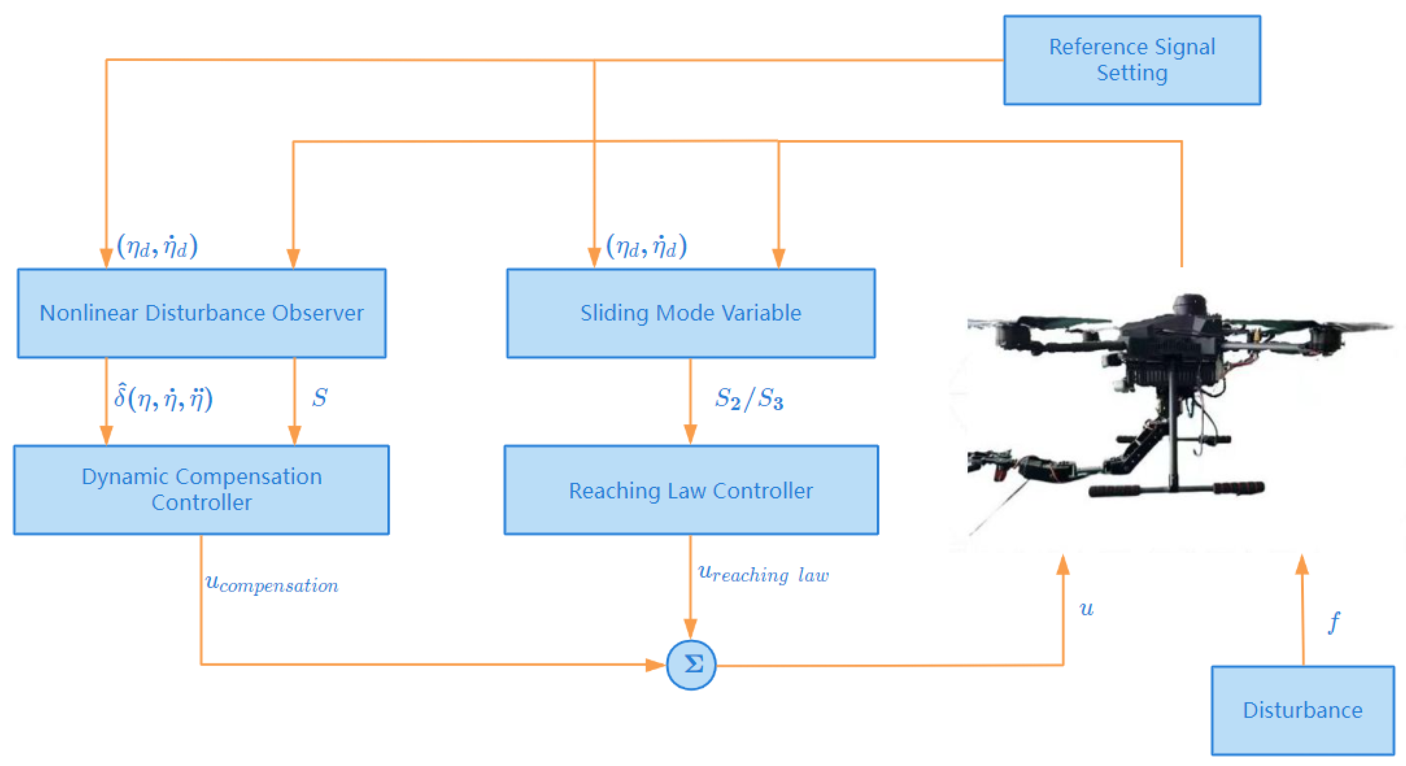
Figure 1. The structure diagram of an aerial manipulation system.
Electronics 13 02746 g001
Figure 2. The actual disturbance and the estimation of disturbance.
Electronics 13 02746 g002
Figure 3. The position tracking control of the aerial manipulation.
Electronics 13 02746 g003
Figure 4. The attitude tracking control of the aerial manipulation.
Electronics 13 02746 g004
Figure 5. The mechanical arm joint angle tracking control of the aerial manipulation.
Electronics 13 02746 g005
Table 1. Aerial Manipulation Physical Parameters.
CharacterDefinitionValue
m b the mass of airframe2 kg
m 1 the mass of mechanical arm joint 10.5 kg
m 2 the mass of mechanical arm joint 20.5 kg
I x x the inertial moment of airframe along x-axis1.24 kg · m 2
I y y the inertial moment of airframe along y-axis1.24 kg · m 2
I z z the inertial moment of airframe along z-axis2.48 kg · m 2
I x 1 the inertial moment of mechanical arm joint 1 along x-axis0.001 kg · m 2
I y 1 the inertial moment of mechanical arm joint 1 along y-axis0.001 kg · m 2
I z 1 the inertial moment of mechanical arm joint 1 along z-axis0
I x 2 the inertial moment of mechanical arm joint 2 along x-axis0.001 kg · m 2
I y 2 the inertial moment of mechanical arm joint 2 along y-axis0.001 kg · m 2
I z 2 the inertial moment of mechanical arm joint 2 along z-axis0
l 1 the extent of mechanical arm joint 10.15 m
l 2 the extent of mechanical arm joint 20.15 m
Disclaimer/Publisher’s Note: The statements, opinions and data contained in all publications are solely those of the individual author(s) and contributor(s) and not of MDPI and/or the editor(s). MDPI and/or the editor(s) disclaim responsibility for any injury to people or property resulting from any ideas, methods, instructions or products referred to in the content.