Article

Reconfigurable CAN Intrusion Detection and Response System

Department of Computer Science and Electrical Engineering, University of Maryland, Baltimore County, MD 21250, USA
*
Author to whom correspondence should be addressed.
Electronics 2024, 13(13), 2672; https://doi.org/10.3390/electronics13132672
Submission received: 15 June 2024 / Revised: 3 July 2024 / Accepted: 4 July 2024 / Published: 7 July 2024
(This article belongs to the Special Issue Security and Privacy in Networks and Multimedia)

Abstract

:
The controller area network (CAN) remains the de facto standard for intra-vehicular communication. CAN enables reliable communication between various microcontrollers and vehicle devices without a central computer, which is essential for sustainable transportation systems. However, it poses some serious security threats due to the nature of communication. According to caranddriver.com, there were at least 150 automotive cybersecurity incidents in 2019, a 94% year-over-year increase since 2016, according to a report from Upstream Security. To safeguard vehicles from such attacks, securing CAN communication, which is the most relied-on in-vehicle network (IVN), should be configured with modifications. In this paper, we developed a configurable CAN communication protocol to secure CAN with a hardware prototype for rapidly prototyping attacks, intrusion detection systems, and response systems. We used a field programmable gate array (FPGA) to prototype CAN to improve reconfigurability. This project focuses on attack detection and response in the case of bus-off attacks. This paper introduces two main modules: the multiple generic errors module with the introduction of the error state machine (MGEESM) module and the bus-off attack detection (BOAD) module for a frame size of 111 bits (BOAD111), based on the CAN protocol presenting the introduction of form error, CRC error, and bit error. Our results show that, in the scenario with the transmit error counter (TEC) value 127 for switching between the error-passive state and bus-off state, the detection times for form error, CRC error, and bit error introduced in the MGEESM module are 3.610 ms, 3.550 ms, and 3.280 ms, respectively, with the introduction of error in consecutive frames. The detection time for BOAD111 module in the same scenario is 3.247 ms.

1. Introduction

Intelligent connected vehicles (ICVs) are currently in a phase of rapid advancement, with intelligence and connectivity being the prevailing trends. A recent study indicates that over 86% of vehicles by the year 2023 will be outfitted with network control systems [1,2,3,4], offering a broader selection of advanced features [5], including vehicle management and adaptive cruise control, as depicted in Figure 1. This figure represents the CAN layout in cars with the CAN bus for linear and star topology connecting various electronic control units (ECUs) through CAN nodes to the CAN bus. The transmission control, adaptive cruise control, and comfort control CAN modules are connected to the CAN bus with linear topology, and rear control and safety control CAN modules are connected to the CAN bus with star topology, where various ECUs are connected to CAN modules as control units.
CAN enables reliable communication between microcontrollers and vehicle devices without a central computer. This efficiency is crucial for electric vehicles (EVs) and hybrid vehicles, where precise control over battery management systems, motor controllers, and other subsystems is essential for optimal performance and energy efficiency and is key to sustainable transportation systems. By allowing multiple microcontrollers to communicate over a single or dual-wire network, CAN reduces the need for complex wiring harnesses. This not only reduces the weight of the vehicle, leading to improved fuel efficiency and reduced emissions, but also lowers production costs and the environmental impact of manufacturing. Moreover, in electric and hybrid vehicles, CAN networks integrate renewable energy sources, such as solar panels, with the vehicle’s energy system. This integration is a crucial aspect of making transportation more sustainable.
Moreover, automobiles establish links with diverse external networks, such as vehicle-to-vehicle (V2V) and vehicle-to-infrastructure (V2I) communication networks, as depicted in Figure 2. This figure exemplifies the communication network consisting of vehicles, cellular base stations, an internet unit, and a roadside unit. This shift turns present-day vehicles into interconnected systems rather than operating in isolation. The more sophisticated the system is and the more connected the vehicle is, the more exposed it is to attacks as mentioned in the Detroit Free Press [6]. To meet the requirements for interfacing with the external networks, the number of ECUs within cars is steadily increasing. Consequently, the complexity of IVNs is also on the rise [5,7,8].
Considering factors such as data volume, response time, reliability, application needs, and other system criteria, there are five frequently employed IVNs: the local interconnect network (LIN), CAN, FlexRay, media-oriented system transport (MOST), and Ethernet. Among these, the CAN protocol is the most widely used, primarily due to its cost-efficiency, reliable performance, and fault tolerance [9].
The CAN communication mentioned above utilizes a bus topology known as the CAN bus to facilitate communication among ECUs, which was originally developed by Bosch for vehicle communication networks. This system allows ECUs to connect without relying on a central host computer. The CAN system enables real-time control by enabling direct message exchange between any pair of nodes and is known for its robust error tolerance [10,11].
Nevertheless, the advantages resulting from improved connectivity and added functionalities do expose evident security weaknesses, including potential threats such as suspension attacks, flooding attacks, spoofing attacks, replay attacks, fuzzing attacks, and masquerade attacks, as outlined in references [5,11,12,13,14].
One of the strategies discussed to counter CAN attacks is the employment of an intrusion detection system (IDS) [13,15]. IVN IDSs are introduced with multiple goals in mind concerning the security of automotive systems. These include the ability to swiftly identify abnormal intrusions (from the adversary or malicious user), furnish accurate reference data for intrusion prevention systems (IPSs), and the capability to prevent further damage resulting from IVN attacks. Early alerts provided by IVN IDS can help mitigate risks posed by malicious adversaries, making it especially suitable for IVN environments with constrained computing and bandwidth resources, as referenced in [16,17,18].
This paper employs a hierarchical approach to building, emulating, and implementing modules for prototyping IDS for CAN structure. For this purpose, the Xilinx Vivado tool is used along with the Nexys A7 board while using Verilog hardware description language (HDL). Here, we calculated the time it takes for the compromised module to enter a `bus-off’ state and recover from it, and we presented it in a graphical format.
Under conditions where errors are introduced in every consecutive frame and every alternate frame, these cases are generated considering the transmit error counter (TEC) value for error state transition between the error-passive state and bus-off state switching between 255 and 127.
The main contributions of this paper are as follows :
  • Create a real scenario environment for an embedded system showcasing a bus-off assault on the CAN accompanied by a method for detecting such an attack.
  • Devise a safeguarding mechanism for CAN communication with a response system designed to counteract potential intrusions.
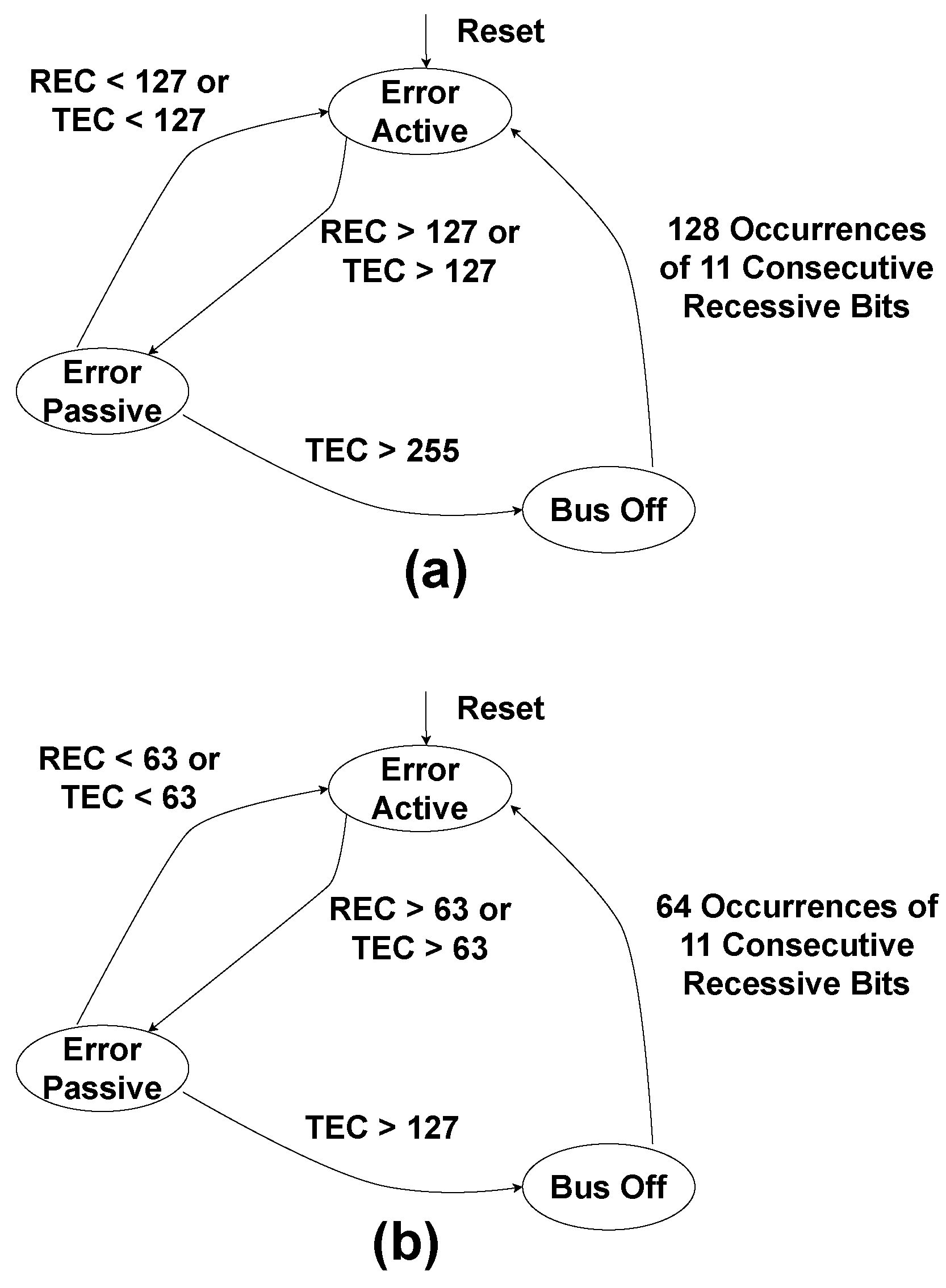
  • Explore different configurations of CAN communication protocol error states on reconfigurable platforms forming part of intrusion detection and intrusion response systems.
  • Introduce a reconfigurable CAN protocol based on a field programmable gate array (FPGA).
The rest of the paper is organized as follows: Section 2 provides background information, Section 3 presents the proposed methodology, and Section 4 provides the experimental setup and results. Finally, Section 5 summarizes the contributions of this work.

2. Background

In this chapter, we first provide an overview of the concept of CAN. Then, we discuss the characteristics and vulnerabilities of IVNs. Additionally, we review the associated attacks. Then, we discuss the constraints of IVN IDSs. Next, we present countermeasures such as IDSs to detect the vulnerabilities. Finally, we discuss the advantages of implementing CAN using the FPGA.

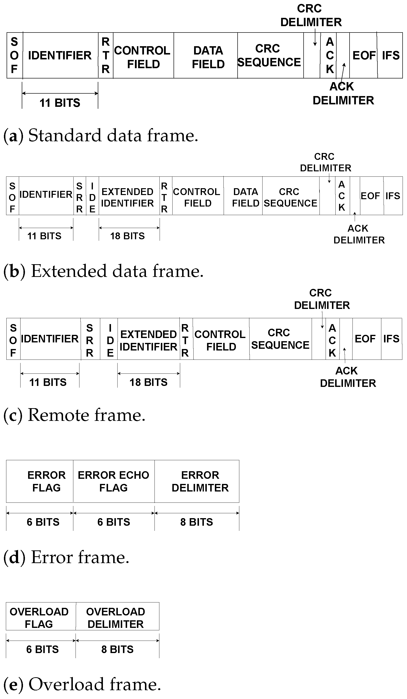
2.1. CAN Preliminaries

The CAN operates as a broadcast-message communication protocol, utilizing bitwise arbitration for contention resolution on the CAN bus. In cases of simultaneous frame transmission by different nodes, the node with the highest priority continues, while the other nodes retry later [19].
The CAN frame includes data, remote, error, and overload frames. A data frame provides data transmission (can be a standard data CAN frame or extended data CAN frame), a remote frame requests data, an error frame signals an error, and an overload frame delays the following message until the current one is processed [20].
A standard data CAN frame composition consists of the following components: start-of-frame (SOF-1 bit), identifier (11 bits), remote transmission request (RTR-1 bit), control field (6 bits), data field (ranging from 0 to 8 bytes), cyclic redundancy check (CRC) field along with CRC delimiter (16 bits), acknowledge (ACK) field along with ACK delimiter (2 bits), end-of-frame (EOF-7 bits), and inter-frame space (3 bits) [21], as shown in Figure 3a. The extended data CAN frame employs 29 bits for identifier arbitration, which includes an identifier field (11 bits) and an extended identifier field (18 bits). Furthermore, the extended data CAN frame also has substitute remote request (SRR-1 bit) and identifier extension (IDE-1 bit), which differentiates standard data CAN frames from extended data CAN frames, and RTR (1 bit) after the extended identifier field [22], as shown in Figure 3b. The remote frame closely resembles the extended data CAN frame but lacks the data field, as shown in Figure 3c. Figure 3 illustrates these three frame types, in addition to the error and overload frames. The error frame consists of the following fields: error flag (6 bits), error echo flag (6 bits), and error delimiter (8 bits), as shown in Figure 3d. Five types of errors can be generated within the CAN frame. These include acknowledge (ACK) error, bit error, CRC error, form error, and stuff error. This paper focuses on the generation and detection of bit error, CRC error, and form error to formulate an attack on the CAN frames. Moreover, bit stuffing is also taken into account in certain cases. The overload frame encompasses the following fields: overload flag (6 bits) and overload delimiter (8 bits), as shown in Figure 3e.
The CAN frame handles up to 8 bytes of data [23], featuring collision detection, error detection, signaling, and fault confinement. The CAN protocol employs static, fixed priority non-preemptive scheduling and accommodates periodic, sporadic, or aperiodic messages [24].

2.2. Characteristics and Vulnerabilities of CAN IVNs

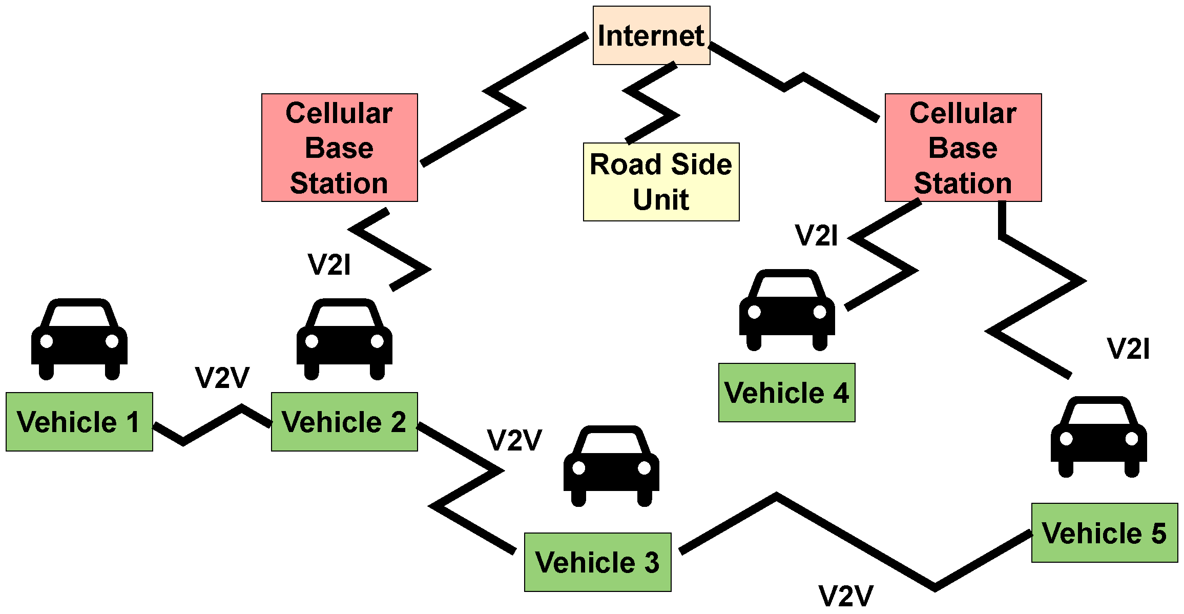
2.2.1. IVN Characteristics

The automotive electronic system functions as a diverse distributed real-time system, with multiple ECUs connected through an IVN that communicates via a central gateway. The IVN is characterized by a heterogeneous distributed real-time system environment, numerous external interfaces, a multi-function safety-critical level system, and a lack of cybersecurity design [16].

2.2.2. Vulnerabilities in CAN-Based IVNs

The CAN bus lacks fundamental security mechanisms in its protocol, leaving vehicles susceptible to malicious adversaries. Six vulnerabilities exist according to the confidentiality, integrity, availability (CIA) security model. These vulnerabilities involve the lack of encryption, authentication, and integrity-checking in CAN bus traffic. Additionally, protocol characteristics such as broadcast transmission, priority-based arbitration, and limited bandwidth introduce vulnerabilities [25]. These vulnerabilities expose IVNs to various attacks, as elaborated in the following section.

2.3. Types of CAN Attacks

The six categories of CAN attack scenarios can be described as follows:
Suspension Attack: To mount a suspension attack, the adversary needs only one weakly compromised ECU. As one type of denial-of-service (DoS) attack, the objective of this attack is to suspend the weakly compromised ECU’s message transmissions, thus preventing the delivery of information it acquired to other ECUs [12].
Flooding Attack: In this attack scenario, an adversary seeks to initiate a DoS attack by inundating the network with a high volume of CAN packets, often with high priority (e.g., CAN ID of 0 × 000) [26].
Spoofing Attack: To disrupt specific vehicle functions (such as gear control or RPM), an adversary injects control packets based on prior knowledge of the target vehicle [27].
Replay Attack: An adversary records regular CAN bus traffic and subsequently replays it onto the CAN bus [28].
Fuzzing Attack: In a fuzzing attack, the adversary generates CAN packets randomly. This attack can lead to unexpected and erratic behavior in the targeted vehicle [5].
Masquerade Attack: In this scenario, a normal ECU’s transmission is halted, allowing a compromised ECU to assume the role of the original ECU by mimicking its CAN IDs and transmission patterns [29].
Out of the six categories of CAN attack scenarios described above, this paper focuses on the detection of a suspension attack to emulate a bus-off condition.

2.4. Constraints of CAN IVN IDS

Constraints in the context of IDSs for IVNs encompass limitations related to hardware, cost, detection accuracy, response time, and standardized construction [13].

2.5. Categories of IVN IDSs

The IVN IDS for CAN can be categorized into three techniques: statistical-based, machine learning-based, and neural network-based.

2.5.1. Statistical-Based IDS for IVN

The IDS, which relies on statistical analysis, assesses message sequences statistically. This approach involves comparing two sets of messages using statistical metrics like cosine similarity, Pearson correlation, and the chi-squared test [30,31]. Suppose there is a notable alteration in message frequencies or sequences indicated by metric values surpassing specified thresholds. In that case, the system predicts the occurrence of intrusions in the subsequent message interval [32]. Another aspect of the statistical analysis for intrusion detection involves assessing message entropy [33,34].

2.5.2. Machine Learning-Based IDS for IVN

In machine learning, three main models are generally employed for prediction: the regression model, the classification model, and the clustering model. The classification-based or clustering-based models find application in real-time intrusion detection scenario prediction [14,35]. Specifically, the classification-based model is suitable for supervised problems, while the clustering-based model is more relevant for unsupervised problems [36].
Supervised machine learning models can be further divided into single classifiers and ensemble learning models. Decision trees (DT) and the k-nearest neighbor (KNN) algorithm serve as examples of single classifiers, while random forest (RF) and extreme gradient boosting (XGBoost) are chosen for ensemble learning models. In the context of semi-supervised learning methods, robust covariance (RC), local outlier factor (LOF), and isolation forest (IF) are selected as baselines [37].
Another study outlined in [38] employed unsupervised learning, a method that operates without the need for labeled data. This unsupervised approach adopted a two-stage process involving deep learning and a probabilistic model.

2.5.3. Neural Network-Based IDS for IVN

Deep and machine learning algorithms have made significant progress and been proven highly effective in anomaly detection [39], demonstrating excellent performance [40]. The neural networks employed for this purpose encompass a range of architectures, including convolutional neural networks (CNNs), long short-term memory (LSTM) neural networks, and advanced models such as the residual neural network (ResNet) and leCun network (LeNet) based on deep transfer learning, as proposed by Mehedi et al. [40]. These models are considered baseline models in the context of anomaly detection [41].
Deep transfer learning (DTL) addresses issues such as limited data availability and the prevalence of application-specific intrusion detection system (IDS) models. The concept revolves around integrating knowledge from a pre-trained source model into a target model. Through this process, DTL facilitates more efficient information amalgamation, potentially yielding superior outcomes compared to training models anew [42]. However, due to a lack of computational power in FGPA, these efforts are limited to GPU-based implementations.

2.6. Advantages of Implementing CAN Protocol on Reconfigurable Computing Platform

FPGAs are highly prized for their ample resources and adaptability as specialized integrated circuits. They play a crucial role in digital electronic design and offer three main benefits [43]. Firstly, FPGA vendors provide robust and user-friendly electronic design tools (EDA), extensive documentation, and personalized support to assist with design and verification. Secondly, unlike application-specific integrated circuits (ASICs) [44], the manufacturing costs for demonstration examples are low [45]. Thirdly, modifications can be implemented at any stage of the design process, thanks to advanced systems that enable dynamic hardware reconfiguration [46,47].
In aerospace and military/aviation critical systems, where programming errors are intolerable, FPGAs’ early-stage design verification feature becomes indispensable. FPGA verification encompasses various processes, such as coding rule checks, manual walkthroughs, functional and timing simulations, static timing analysis, cross-clock domain checks, and logical equivalence checks. Functional simulation, in particular, holds significant importance in ensuring design reliability, a critical consideration given the exponential growth of verification cases with increasing design scale [48]. Implementation of CAN protocol on FPGA allows researchers to prototype different IDS quickly and allows adaptability with varying CAN speeds.

3. Proposed Methodology

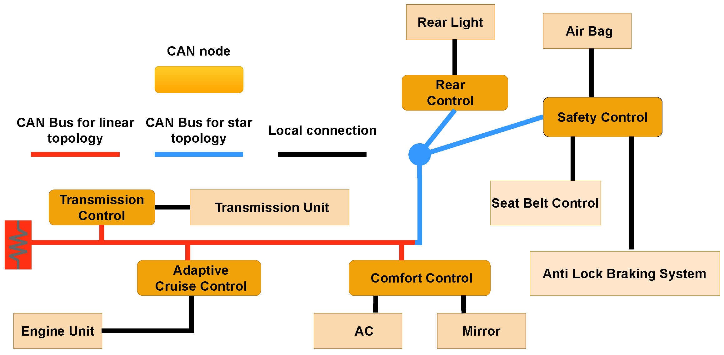
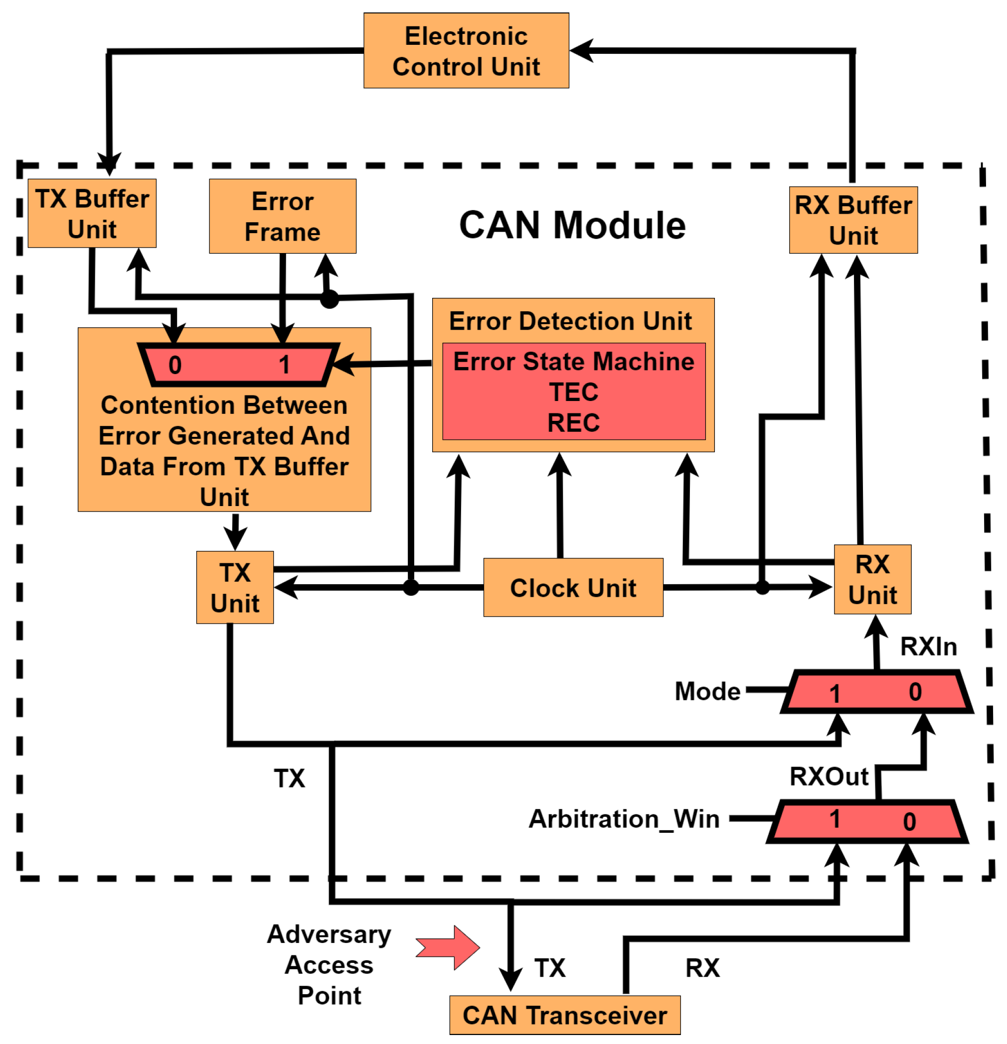
3.1. CAN Architecture

Figure 4 shows the basic architecture of the CAN module interacting with the ECU on one end and the CAN transceiver connected to the CAN bus on the other end. The CAN module comprises a transmission buffer unit (TX buffer unit) and a reception buffer unit (RX buffer unit). The data are fed into the transmission buffer unit from the ECU with a frame size of 111 bits (for standard frame size) and are received from the reception buffer unit with a frame size of 111 bits (for standard frame size) into the ECU. In addition, there is a transmitting unit (TX Unit), a reception unit (RX Unit), and an error detection unit. The clock unit maintains synchronization by connecting to transmission, reception, and error detection units along with the TX buffer unit and RX buffer unit. The data are transmitted between various units within the CAN module one bit at a time with respect to the clock signal. The flow of data is from the RX unit to the RX buffer unit. For data flow on the transmission side, there is a contention between data from the TX buffer unit and error frame based on the error generation signal from the error detection unit. The data are passed onto the TX unit. The data flows between the TX unit and the CAN transceiver and also between the CAN transceiver and RX Unit. On the other side of the CAN transceiver is the CAN bus.

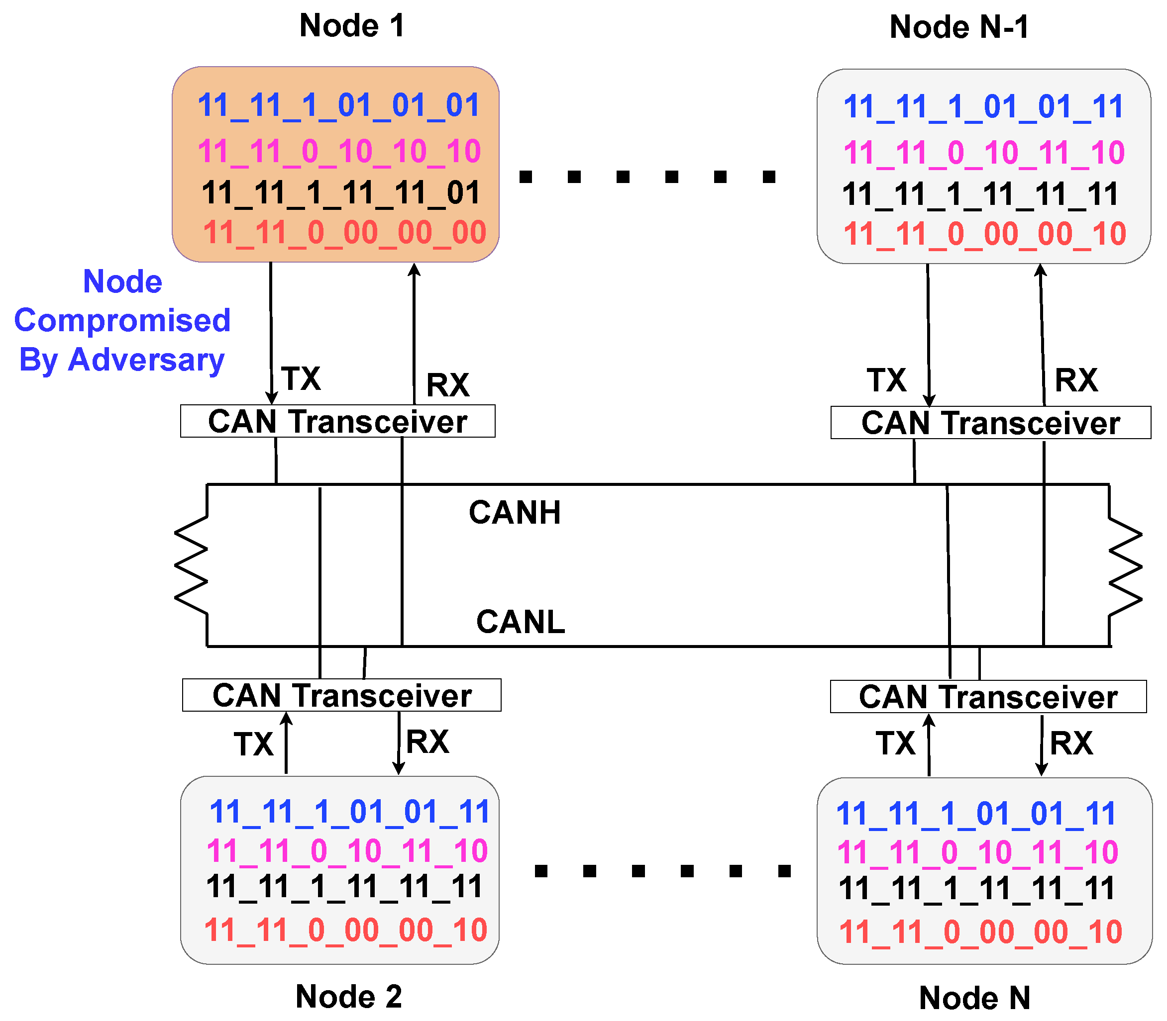
3.2. Communication among CAN Nodes over CAN Bus

The communication network of the CAN modules over the CAN bus is shown in Figure 5. Here, we present N nodes with one compromised node (the adversary has access to CAN bus through this node) and N 1 normal nodes. The identifier values highlighted in different colors indicate which identifiers among different nodes will be considered at a respective time stamp for arbitration, as can be seen in Figure 5. Node 1, which the adversary compromises, has the lowest arbitration ID values at all the time stamps. So, communication is dominated by the data from this node.

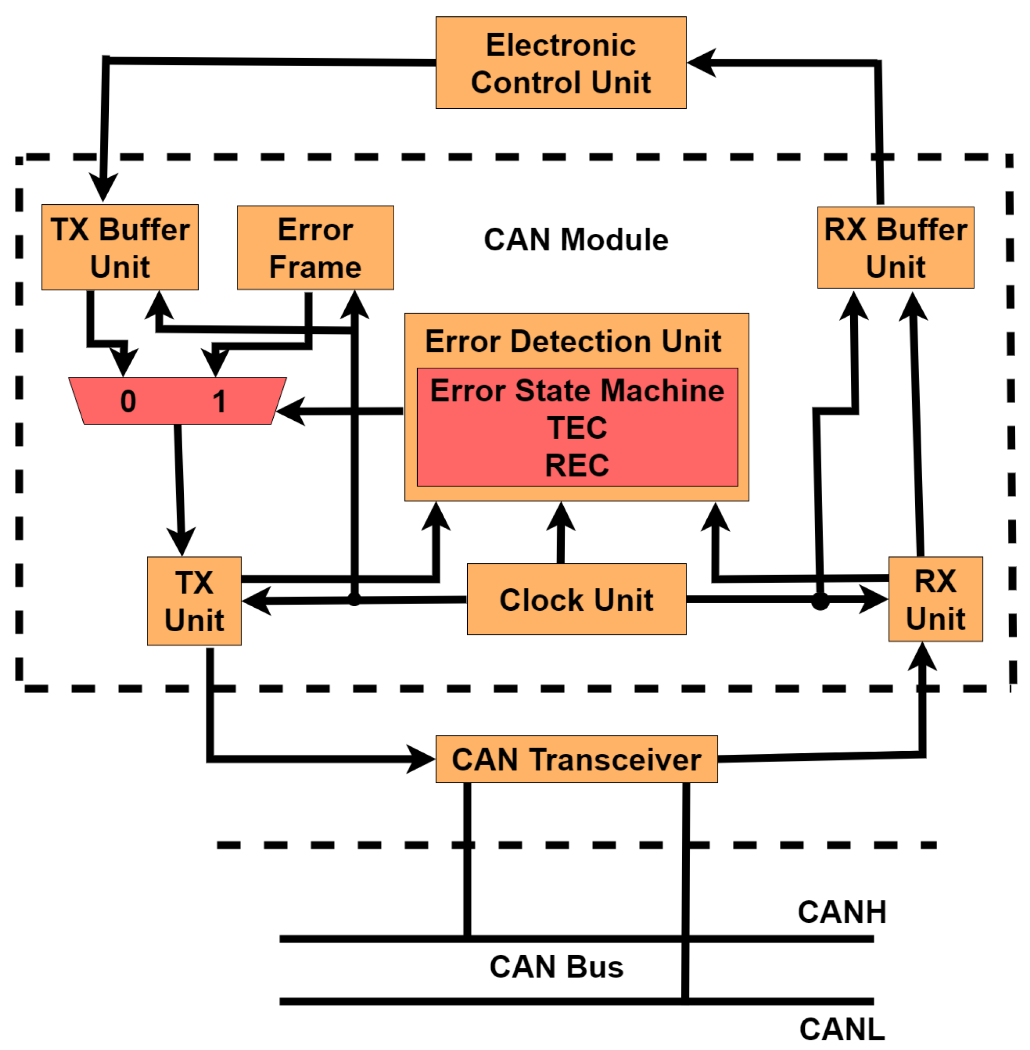
3.3. Proposed Intrusion Detection and Intrusion Response Systems

We utilized the concept of a bus-off state, which is associated with a scenario when a node fails to transmit data frames and the associated error counter reaches a specified value. In order to detect a bus-off attack, the CAN module needs to enter the bus-off state. Furthermore, the CAN module also comes out of the bus-off state after the transmission of a specific number of recessive bits. The detection time is the time for the CAN module to enter the bus-off state. The response time is the time for the CAN module to come out of the bus-off state.
The transition of the CAN node from the error-passive state into the bus-off state and back into the error-active state is represented in two error state diagrams based on the values of the transmit error counter (TEC) and the receive error counter (REC) [21]. Figure 6 illustrates respective error state diagrams. In Figure 6a, a TEC value of 127 facilitates the transition from the error-active state to the error-passive state. A TEC value of 255 is required to shift from the error-passive state to the bus-off state. The transition from bus-off to error-active states involves the transmission of 128 × 11 recessive bits. Similarly, in Figure 6b, the TEC value for moving from error-active to error-passive states is 63, while transitioning from error-passive to bus-off states requires a TEC value of 127. The shift from bus-off to error-active states involves the transmission of 64 × 11 recessive bits. Hence, using two error state diagrams for the threat models signifies the reconfigurability of the CAN prototype on the FPGA.
Setting the TEC value at 255 as the threshold for transitioning from error-passive to bus-off in the CAN protocol aims to establish a distinct separation between these error states. This choice signifies a severe and persistent communication issue triggered after detecting a significant number of errors. The 8-bit TEC counter ranges from 0 to 255, and the transition to bus-off occurs when TEC reaches the maximum value, providing a clear signal of persistent communication problems.
While a TEC value of 127 allows configurability, values lower than 127 are avoided to prevent frequent entries into the bus-off state. This precaution guards against heightened sensitivity to transient errors, maintaining a balance between error sensitivity and system robustness. Lowering the threshold too much could prompt quicker error responses but might also increase the likelihood of nodes being excluded due to false positives or transient issues.
In summary, the entry of the CAN module into the bus-off state is represented as intrusion detection, for which detection time is computed. Furthermore, exiting the CAN module from the bus-off state is represented as an intrusion response for which response time is calculated.

3.4. Threat Model for Individual CAN Nodes Interacting over CAN Bus

The threat model is shown in Figure 7. This threat model in the research is consistent with the existing literature, as mentioned in [49]. The assumption here is that the adversary can eavesdrop on the TX signal coming out of the CAN module and going into the CAN transceiver from that CAN module. Due to the adversary’s access to the TX signal, the adversary manipulates the logic value placed on the line going into the CAN transceivers.
The threat model is built on the basic architecture shown in Figure 4. In this threat model, data transmission and reception happens one bit at a time with respect to the clock signal. However, transmission from and reception to the ECU from the CAN module is considered for a 111 bit frame size (standard frame size). The T X signal outputted with the adversary access point is sent to the CAN transceiver from the TX Unit. This signal and the R X signal from the CAN transceiver are input to a multiplexer within the CAN module with A r b i t r a t i o n _ W i n as the select signal. The output of this multiplexer, R X O u t , is put as input to the second multiplexer, which has its second input coming from the T X line of the CAN module, and R X I n is its output with M o d e as a select signal sent to the RX Unit. The error is generated based on comparing T X and R X I n signals within the error detection unit. There is contention between data from the TX buffer unit and error frame with respect to the error signal generated from the error detection unit. The contented data are put onto the TX unit, from where the data are sent as input to the CAN transceiver and multiplexer with A r b i t r a t i o n _ W i n as the select signal.
The types of errors introduced include form, CRC, and bit errors. When the bus-off attack comes into the picture through multiple occurrences of any of the errors, the communication on the CAN bus is stopped. However, an inner transition from T X to R X I n still occurs (based on the value of the M o d e signal). The communication happens bit by bit in each clock cycle. The transfer of 11 × 128 recessive bits in one case and 11 × 64 recessive bits in the second case puts the node back into the network for communication (transmission from bus-off state to error-active state) on the CAN bus for transmission and reception.

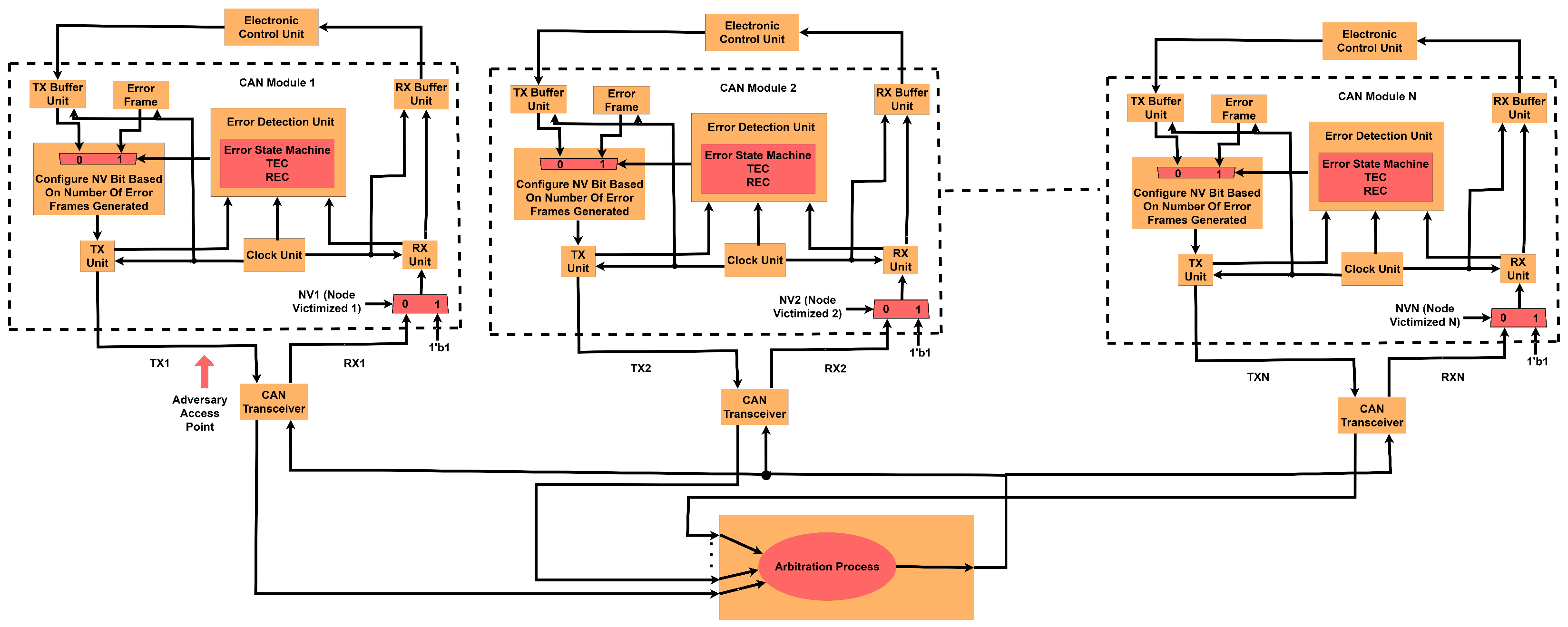
3.5. Threat Model for Interaction of Multiple CAN Nodes

Figure 8 shows communication among N nodes over the CAN bus presented in Figure 5. In this threat model, data transmission and reception occurs one bit at a time with respect to the clock signal in all the respective CAN modules, with the transmission from and reception to ECU from the CAN modules happening for a frame size of 111 bits (standard frame size considered). When multiple CAN nodes interact with the CAN bus, each CAN module outputs the signal from the TX Unit to the CAN transceiver. The adversary has access to the TX line of CAN module 1, on which it injects an inverted signal with respect to the CAN signal from the respective CAN module at a specific time stamp. The compromised output is sent to the arbitration process unit, which also has signals from all other CAN modules ( N 1 modules). Based on the arbitration process, after the contention between the signals from all the CAN modules, one signal wins the arbitration, and that signal is broadcast to all CAN transceivers. The RX signals from all the CAN transceivers are sent to CAN modules. The error frame is generated based on the comparison between received and transmitted signals within the CAN modules. Upon generation of enough error frames, the N V ( N o d e V i c t i m i z e d ) signal is set, and it puts that particular node in the bus-off state in which the recessive bit is passed through from the reception line into the RX Unit of the respective CAN module.
Algorithm 1 explains Figure 8. The input in Line 1 of the algorithm consists of N standard CAN messages. The output of the algorithm is the data being fed into the RX units. In Line 3, the TEC values and node victimized (NV) values are set to zero for all N CAN modules. Iterating over N CAN modules in lines 4–9, the TX signal is fed in the signal from the respective standard CAN messages in Line 5. Next, in Line 6, the TXCompromised signal is fed with the TX value for all modules except the compromised one. For the compromised module, there is a bit flip with respect to the TX signal at a specific position in the standard CAN message that is being provided to the TXCompromised signal. Finally, the TXCompromised signals are placed onto the respective TXCANTransceivers for all N modules in Line 7. In Line 8, the R X i signal is given the result of the a r b i t r a t i o n p r i o r i t y ( ) function, where the signals from all CAN transceivers contest for the bus and only one signal with the highest arbitration priority is selected as output. In Lines 10 to 15, the “For loop” iterates over all N modules and checks for if the condition does not match the R X i signal to the TXCompromisedi signal in Line 11. Based on this if statement, the NVi signal is assigned a value of zero in Line 12. The R X U n i t i is fed with either a recessive bit stream (RBS) or an R X i based on the NVi signal using the f e t c h d a t a ( ) function, as shown in Line 14. The RBS consists of a stream of logic one values. The next “For loop”, in Lines 16 to 33, again iterates over all N modules, conditionally updating T E C values using the e r r o r g e n e r a t i o n ( ) function. The condition on T E C i being greater than 255 sets the N V i value to one. Based on the N V i , the RXUniti is fed with either a RBS or a R X i using the f e t c h d a t a ( ) function in Line 30.
Algorithm 1 shows the transfer of a node to a bus-off state for the TEC value exceeding a value of 255. The value for TEC chosen for transition between states is large enough to separate the attack from a malfunction in terms of false positives.
Algorithm 1 The bus-off attack detection and response algorithm.
1:
Input: Standard CAN messages
2:
Output: Data into RXUnits
3:
Initialize: T E C i ← 0 and N V i ← 0 for i from 1 to N ▹ Transmit error counteri (TECi), node victimizedi (NVi)
4:
for i ← 1 to N do
5:
    TXi ← transmitframe(Standard CAN messagei)  ▹ Transmitting Standard CAN message
6:
    TXCompromisedi ← adversarysccess(TXi)      ▹ Transmitting TX signal with compromised value at a specific position within the message frame for a specific module and without a compromised value for rest of the modules.
7:
    TXCANTransceiveri ← TXCompromisedi  ▹ Value assigned to CAN transceiver from TX signal
8:
     R X i ← arbitrationpriority(TXCANTransceiveri)  ▹ Result of arbitration process moved into RX signal
9:
end for
10:
for i ← 1 to N do
11:
    if  R X i ! = T X C o m p r o m i s e d i  then
12:
        NVi ← 0
13:
    end if
14:
    RXUniti ← fetchdata( N V i , RBS, R X i )  ▹ Putting data into CAN RXUniti based on NVi from either recessive bit stream (RBS) or R X i
15:
end for
16:
for i ← 1 to N do
17:
    if  R X i == T X C o m p r o m i s e d i  then
18:
        while  T E C i <= 255 do
19:
            Error i ← errorgeneration( T X i , R X i )
20:
           if  E r r o r i == 1 then
21:
                T E C i T E C i + 8
22:
           else
23:
                T E C i T E C i − 1
24:
           end if
25:
           if  T E C i > 255 then
26:
                N V i ← 1
27:
           else
28:
                N V i ← 0
29:
           end if
30:
           RXUniti ← fetchdata( N V i , RBS, R X i )   ▹ Putting data into CAN RXUniti based on N V i from either RBS or R X i
31:
        end while
32:
    end if
33:
end for

4. Experimental Results

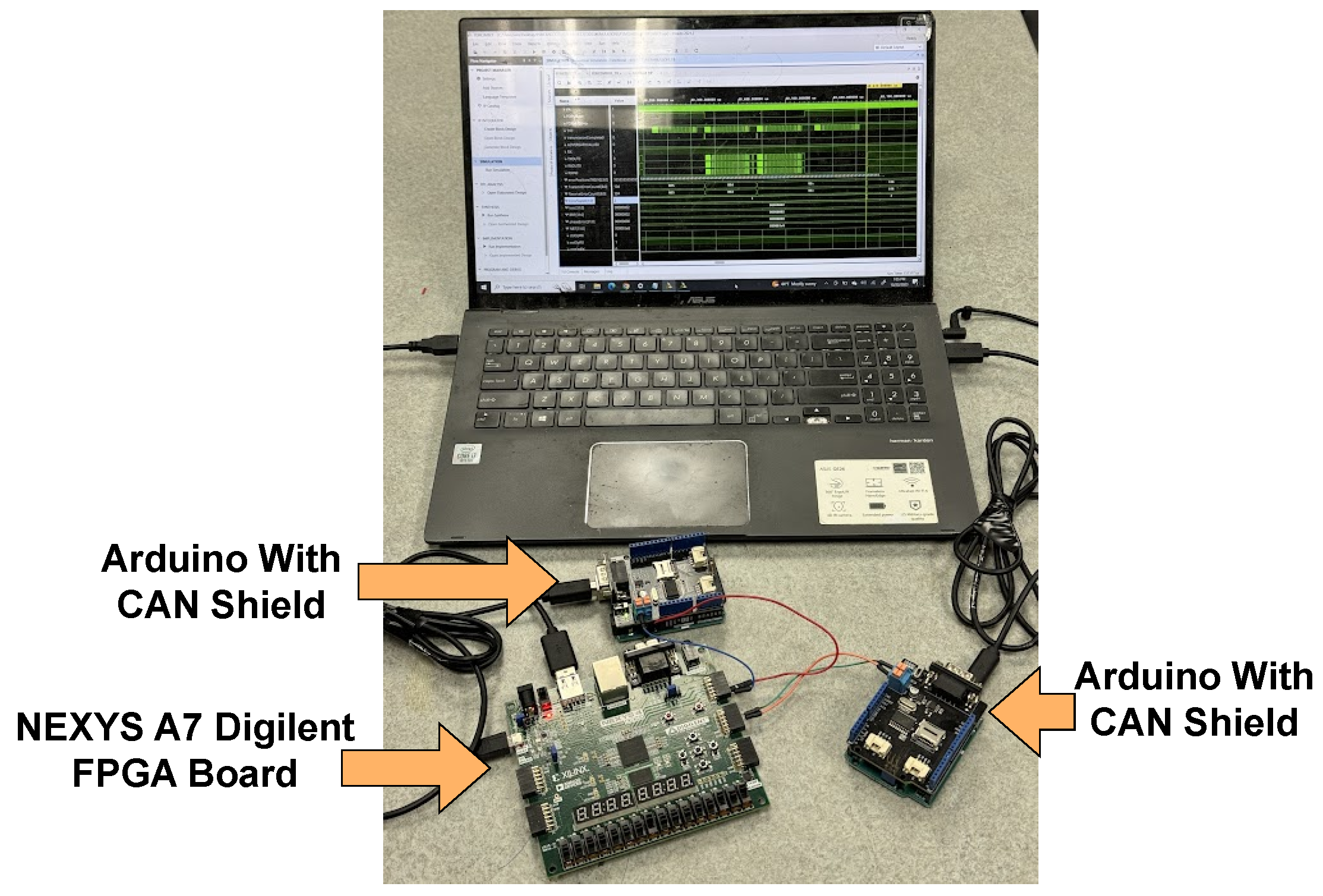
4.1. Experimental Setup

The Xilinx Vivado tool is used for coding in Verilog and seeing the simulation results for the modules created to emulate the behavior of CAN. The implementation of CAN functionality is observed on the NEXYS A7 Digilent board, which is coded using the Xilinx Vivado tool and passes through synthesis, implementation, and bitstream generation phases before programming the board through the hardware manager. The hardware setup used in this project is shown in Figure 9. The figure shows the interaction between Arduino and the CAN shield and FPGA, in which CAN logic is prototyped. The clock period used for the simulation of modules is 1 microsecond (to match the 1 Mbps speed of CAN protocol).
Figure 10 illustrates an example of simulation results for the MGEESM module with the transmission of form error in every alternate standard frame with a length of 111 bits by showing the transition between the error-passive state and the bus-off state as the transmit error counter exceeds value 255. Similarly, Figure 11 illustrates an example of simulation results for the MGEESM module with the transmission of form error in every alternate standard frame with a length of 111 bits by showing the transition between the bus-off state and the error-active state after transmission of 128 occurrences of 11 consecutive recessive bits. The form error occurs at a position of 20 bits after the end of the data field within the standard frame.
We designed several modules to implement a configurable CAN protocol and attack detection and response system, which are listed in Table 1. The TX module is the primary transmission module with options to output a standard frame, extended frame, or remote frame, with the length of the message varying from zero to eight bytes. The RX module is the basic reception module for receiving frames of standard, extended, or remote types as input and storing them in receiver buffers based on specific criteria. The GE module stands for the generic error module, which introduces the form error, CRC error, and bit error within the single frame outputted from the CAN node. The GE module is built on top of the TX and RX modules.
Next, we have the MGE module. The MGE module stands for the multiple generic errors module presenting form errors, CRC errors, and bit errors in various frames within a single CAN node. This module is built hierarchically on top of the GE module. The MGEESM module represents multiple generic errors, including multiple form errors, multiple CRC errors, and multiple bit errors, respectively, with the introduction of the error state machine. This module is put in place based on the MGE module.
The next set of modules indicates the communication between multiple nodes over the CAN bus, as shown in Figure 8. For error-free processing of the CAN protocol in interactions among a network of multiple CAN nodes, MCIWOERROR111 refers to multiple CAN nodes’ interaction without error for a frame size of 111 bits.
Conversely, the multiple CAN nodes interaction with error introduction for a frame size of 111 bits (MCIWITHERROR111 module) is employed to introduce errors in communication among multiple nodes over the CAN bus. Lastly, the bus-off attack detection module for a frame size of 111 bits (BOAD111 module) incorporates an error state machine to represent error generation within a CAN node communicating among multiple CAN nodes over the CAN bus.

4.2. Results

We define the attack/error detection time as the time for the victim node to enter the bus-off state. The response time is the time for the victim node to come out of the bus-off state. Both detection and response times are measured for the victim node in two scenarios. In both scenarios, four sub-cases were examined with TEC value for switching between error-passive state and bus-off state. In the initial sub-case, an error introduction was simulated in every frame with a TEC value of 255. For the second sub-case, an error introduction with a TEC value of 255 was applied in every alternate frame. In the third sub-case, the error was introduced in every frame as modeled with a TEC value of 127. Finally, the fourth sub-case involves error introduction in every alternate frame, utilizing a TEC value of 127.
In the first scenario, only one node (victim node) interacts over the CAN bus. In this case, specific errors are introduced (within the MGEESM module), which are form error, CRC error, and bit error. The purpose of these errors is to induce a bus-off attack within the CAN modules. Here, the data length of the frame considered is eight bytes for the standard frame with the inclusion of bit stuffing violation. The results for this scenario are shown in Figure 12. For form error, an error is introduced 20 positions after the end of the data field within the frame. For CRC error, an error is introduced 42 positions before the end of the data field within the frame. For bit error, an error is introduced two positions before the end of the data field within the frame.
In the initial sub-case of the first scenario, the detection times for form error, CRC error, and bit error are 7.322 ms, 7.198 ms, and 6.640 ms, respectively, as shown in Figure 12a. In the second sub-case of the first scenario (TEC = 255), the detection times for form error, CRC error, and bit error are 12.478 ms, 12.334 ms, and 11.686 ms, respectively, as shown in Figure 12b. In the third sub-case of the first scenario, the detection times are 3.610 ms, 3.550 ms, and 3.280 ms for form error, CRC error, and bit error, respectively, as shown in Figure 12c. Moving onto the fourth sub-case in the first scenario, the detection times for form, CRC, and bit errors are 6.304 ms, 6.232 ms, and 5.908 ms, as shown in Figure 12d. Figure 12 shows that form error requires the highest detection time for all four sub-cases in the first scenario, and bit error requires the lowest detection time. However, the response time remains constant across all sub-cases with a value of 1.408 ms for a TEC value of 255 and 0.704 ms for a TEC value of 127. Though the response time is constant with respect to TEC value across all four sub-cases, it is included to give a comprehensive view of the result generated for the four sub-cases for the first scenario.
In the second scenario, the victim node interacts with other nodes over the CAN bus. The focus is on emulating the entire network. Here, a frame size of 111 bits (for the BOAD111 module) is considered. The arbitration IDs considered are 11 bits. The results for this scenario are shown in Figure 13. In this case, the error is introduced at position 60 within the frame with an error field size of 20 bits. The purpose of the error introduced here is to induce a bus-off attack in the CAN module communicating with multiple CAN modules. No bit stuffing violation is considered for this scenario.
In the first sub-case of the second scenario, the detection time for the BOAD111 module is 6.303 ms, as shown in Figure 13a. The detection time is 11.174 ms for the BOAD111 module for the second sub-case, as shown in Figure 13b. In the third sub-case of the second scenario, detection times of 3.247 ms are observed for the BOAD111 module, as shown in Figure 13c. In the fourth sub-case of the second scenario, detection times of 5.738 ms are noted for the BOAD111 module, as shown in Figure 13d.
The response time remains constant in all sub-cases: 1.408 ms for the sub-case with a TEC value of 255 and 0.704 ms for the sub-case with a TEC value of 127. Again, though the response time is constant regarding TEC value across all four sub-cases, it is included to give a comprehensive view of the result generated for the four sub-cases for the second scenario.
For the two modules (MGEESM and BOAD111), this analysis presents utilization parameters (Slice LUTs, Slice Registers, Slice, LUT as Logic, Bonded IOB, BUFGCTRL, F7 Muxes, and F8 Muxes). Moreover, this analysis presents latency values, power metrics, and energy values across four sub-cases for two modules (with the introduction of form error, CRC error, and bit error in the MGEESM module).
Table 2 presents detailed information concerning the utilization parameters linked to the MGEESM and BOAD111 modules. The BUFGCTRL utilization parameter has the same value for both modules. Moreover, the results for LUT as a logic utilization parameter are the same as those for Slice LUTs utilization parameters for both modules. The Slice LUTs utilization parameter has a value of 2299 for the MGEESM module. This parameter has a value of 2663 for the BOAD111 module. The Slice Registers utilization parameter has a value of 595 for the MGEESM module, while this parameter has a value of 662 for the BOAD111 module. Moreover, the Slice utilization parameter has values of 794 and 897 for the MGEESM and BOAD111 modules, respectively. The Bonded IOB utilization parameter has a value of 26 for the MGEESM module and 21 for the BOAD111 module. In addition, module MGEESM has values of 92 and 1 for F7 Muxes and F8 Muxes utilization parameters, respectively.
Table 3 provides latency, power, and energy data for four sub-cases pertaining to the two modules mentioned before. The table includes details related to form error, CRC error, and bit error introduction in the MGEESM module, along with the results for the BOAD111 module.
In the first set of comparisons, CRC error exhibits a latency of 1.42% lower than form error, while bit error demonstrates a 7.81% decrease in latency compared to form error. Conversely, BOAD111 shows a latency of 7.711 ms. Power consumption for CRC error and bit error is the same as that of form error. The power consumption for BOAD111 is 0.115 W. However, CRC error consumes 1.42% less energy than form error, and bit error consumes 7.81% less energy. The energy consumption value for BOAD111 is 0.887 mJ.
In the second sub-case, CRC error demonstrates a 1.04% decrease in latency compared to form error, with bit error showing a 5.70% reduction. BOAD111 exhibits a latency of 12.582 ms. Power consumption for CRC error and bit error is the same as that of form error. Power consumption for BOAD111 is 0.115 W. However, CRC error consumes 1.04% less energy, and bit error consumes 5.70% less energy than form error. BOAD111 has an energy consumption of 1.447 mJ.
In the third sub-case, CRC error and bit error demonstrate latency reductions of 1.39% and 7.65%, respectively, compared to form error. BOAD111 shows a latency of 3.951 ms. Power consumption for CRC error and bit error remains the same as for form error, with CRC error consuming 1.39% less energy and bit error consuming 7.65% less energy. BOAD111’s power consumption is 0.115 W, with an energy consumption of 0.454 mJ.
In the fourth set of comparisons, CRC error and bit error demonstrate latency reductions of 1.03% and 5.65%, respectively, compared to form error. BOAD111 shows a latency of 6.442 ms. CRC error and bit error consume the same power as form error. CRC error energy consumption is 1.03% lower, and bit error is 5.65% lower than form error. BOAD111’s power consumption is 0.115 W, but its energy consumption is 0.741 mJ.

5. Conclusions

This research project aimed to assess the susceptibility of the CAN to bus-off attacks by emulating them on an FPGA. The configurability and security of the CAN communication protocol were investigated in this project. The MGEESM module with the introduction of form error, CRC error, and bit error was covered in the first threat model. Furthermore, the BOAD111 module was covered in the second threat model.
This paper also experimentally examined the detection and response times for both the modules covered in both threat models.
These times were compared for respective modules within the threat models. Moreover, the latency, utilization parameters, power, and energy were compared for respective modules considering two threat models. The advantage of this implementation of the CAN protocol and attack scenarios using FPGAs is that changes in clock speed can be easily accommodated within the design without changes in the overall structure of the modules. This is useful for further investigation of the CAN protocol based on varying CAN speeds and other threat models and considering different attacks. Furthermore, in electric and hybrid vehicles, CAN networks integrate renewable energy sources, making transportation more sustainable.

Author Contributions

Conceptualization, R.I.; methodology, R.I. and R.S.; software, R.I. and R.S.; validation and analysis, R.I. and R.S.; investigation, R.I. and R.S.; writing—original draft preparation, R.I. and R.S.; writing—review and editing, R.I.; supervision, R.I.; project administration, R.I.; funding acquisition, R.I. All authors have read and agreed to the published version of the manuscript.

Funding

This research was funded in part by a UMBC start up grant and the National Science Foundation (NSF) award, number: 2138253.

Data Availability Statement

The original contributions presented in the study are included in the article material, further inquiries can be directed to the author with correspondence email.

Conflicts of Interest

The authors declare no conflicts of interest.

References

  1. Wei, H.; Ai, Q.; Zhai, Y.; Zhang, Y. Automotive Security: Threat Forewarning and ECU Source Mapping Derived From Physical Features of Network Signals. IEEE Trans. Intell. Transp. Syst. 2023, 25, 2479–2491. [Google Scholar] [CrossRef]
  2. Tan, Z.; Dai, N.; Su, Y.; Zhang, R.; Li, Y.; Wu, D.; Li, S. Human—Machine interaction in intelligent and connected vehicles: A review of status quo, issues, and opportunities. IEEE Trans. Intell. Transp. Syst. 2021, 23, 13954–13975. [Google Scholar] [CrossRef]
  3. Siegel, J.E.; Erb, D.C.; Sarma, S.E. A survey of the connected vehicle landscape—Architectures, enabling technologies, applications, and development areas. IEEE Trans. Intell. Transp. Syst. 2017, 19, 2391–2406. [Google Scholar] [CrossRef]
  4. Su, Z.; Dai, M.; Xu, Q.; Li, R.; Zhang, H. UAV enabled content distribution for internet of connected vehicles in 5G heterogeneous networks. IEEE Trans. Intell. Transp. Syst. 2021, 22, 5091–5102. [Google Scholar] [CrossRef]
  5. Sunny, J.; Sankaran, S.; Saraswat, V. A Hybrid Approach for Fast Anomaly Detection in Controller Area Networks. In Proceedings of the 2020 IEEE International Conference on Advanced Networks and Telecommunications Systems (ANTS), New Delhi, India, 14–17 December 2020; pp. 1–6. [Google Scholar] [CrossRef]
  6. Blanco, S. Car Hacking Danger Is Likely Closer than You Thinkt. Available online: https://www.caranddriver.com/news/a37453835/car-hacking-danger-is-likely-closer-than-you-think/ (accessed on 1 April 2024).
  7. Shin, C. A framework for fragmenting/reconstituting data frame in Controller Area Network (CAN). In Proceedings of the 16th International Conference on Advanced Communication Technology, Pyeongchang, Republic of Korea, 16–19 February 2014; pp. 1261–1264. [Google Scholar] [CrossRef]
  8. Ullah, K. On the Use of Opportunistic Vehicular Communication for Roadside Services Advertisement and Discovery. Ph.D. Thesis, Universidade de São Paulo, São Paulo, Brazil, 2016. [Google Scholar]
  9. Zhang, X.; Cui, X.; Cheng, K.; Zhang, L. A Convolutional Encoder Network for Intrusion Detection in Controller Area Networks. In Proceedings of the 2020 16th International Conference on Computational Intelligence and Security (CIS), Guangxi, China, 27–30 November 2020; pp. 366–369. [Google Scholar] [CrossRef]
  10. Choi, E.; Han, S.; Choi, J.W. Channel capacity analysis for high speed controller area network (CAN). In Proceedings of the 2015 International Conference on Information and Communication Technology Convergence (ICTC), Jeju, Republic of Korea, 28–30 October 2015; pp. 188–190. [Google Scholar] [CrossRef]
  11. Jeong, Y.; Kim, H.; Lee, S.; Choi, W.; Lee, D.H.; Jo, H.J. In-Vehicle Network Intrusion Detection System Using CAN Frame-Aware Features. IEEE Trans. Intell. Transp. Syst. 2023, 25, 3843–3853. [Google Scholar] [CrossRef]
  12. Cho, K.T.; Shin, K.G. Fingerprinting electronic control units for vehicle intrusion detection. In Proceedings of the 25th USENIX Security Symposium (USENIX Security 16), Austin, TX, USA, 10–12 August 2016; pp. 911–927. [Google Scholar]
  13. Jo, H.J.; Choi, W. A Survey of Attacks on Controller Area Networks and Corresponding Countermeasures. IEEE Trans. Intell. Transp. Syst. 2022, 23, 6123–6141. [Google Scholar] [CrossRef]
  14. Islam, R.; Devnath, M.K.; Samad, M.D.; Al Kadry, S.M.J. GGNB: Graph-based Gaussian naive Bayes intrusion detection system for CAN bus. Veh. Commun. 2022, 33, 100442. [Google Scholar] [CrossRef]
  15. Ansari, M.R.; Yu, S.; Yu, Q. IntelliCAN: Attack-resilient Controller Area Network (CAN) for secure automobiles. In Proceedings of the 2015 IEEE International Symposium on Defect and Fault Tolerance in VLSI and Nanotechnology Systems (DFTS), Amherst, MA, USA, 12–14 October 2015; pp. 233–236. [Google Scholar] [CrossRef]
  16. Wu, W.; Li, R.; Xie, G.; An, J.; Bai, Y.; Zhou, J.; Li, K. A Survey of Intrusion Detection for In-Vehicle Networks. IEEE Trans. Intell. Transp. Syst. 2020, 21, 919–933. [Google Scholar] [CrossRef]
  17. Khandelwal, S.; Shreejith, S. A Lightweight FPGA-based IDS-ECU Architecture for Automotive CAN. In Proceedings of the 2022 International Conference on Field-Programmable Technology (ICFPT), Hong Kong, China, 5–9 December 2022; pp. 1–9. [Google Scholar]
  18. Islam, R.; Refat, R.U.D. Improving CAN bus security by assigning dynamic arbitration IDs. J. Transp. Secur. 2020, 13, 19–31. [Google Scholar] [CrossRef]
  19. Pollicino, F.; Stabili, D.; Marchetti, M. Performance comparison of timing-based anomaly detectors for Controller Area Network: A reproducible study. Acm Trans.-Cyber-Phys. Syst. 2023, 8, 1–24. [Google Scholar] [CrossRef]
  20. Tariq, S.; Lee, S.; Woo, S.S. CANTransfer: Transfer learning based intrusion detection on a controller area network using convolutional LSTM network. In Proceedings of the 35th annual ACM symposium on applied computing, Brno, Czech Republic, 30 March–3 April 2020; pp. 1048–1055. [Google Scholar]
  21. Microchip, C. Controller MCP2515 Datasheet. Available online: https://ww1.microchip.com/downloads/aemDocuments/documents/APID/ProductDocuments/DataSheets/MCP2515-Family-Data-Sheet-DS20001801K.pdf (accessed on 1 April 2023).
  22. Zhang, L. Intrusion Detection Systems to Secure In-Vehicle Networks. Ph.D. Thesis, University of Michigan-Dearborn, Dearborn, MI, USA, 2023. [Google Scholar]
  23. Han, K.; Mun, H.; Balakrishnan, M.; Yeun, C.Y. Enhancing security and robustness of Cyphal on Controller Area Network in unmanned aerial vehicle environments. Comput. Secur. 2023, 135, 103481. [Google Scholar] [CrossRef]
  24. Olufowobi, H.; Young, C.; Zambreno, J.; Bloom, G. Saiducant: Specification-based automotive intrusion detection using controller area network (can) timing. IEEE Trans. Veh. Technol. 2019, 69, 1484–1494. [Google Scholar] [CrossRef]
  25. Zhang, H.; Meng, X.; Zhang, X.; Liu, Z. CANsec: A practical in-vehicle controller area network security evaluation tool. Sensors 2020, 20, 4900. [Google Scholar] [CrossRef] [PubMed]
  26. Park, S.B.; Jo, H.J.; Lee, D.H. Flooding attack mitigator for in-vehicle CAN using fault confinement in CAN protocol. Comput. Secur. 2023, 126, 103091. [Google Scholar] [CrossRef]
  27. Humayed, A.; Li, F.; Lin, J.; Luo, B. Cansentry: Securing can-based cyber-physical systems against denial and spoofing attacks. In Proceedings of the Computer Security—ESORICS 2020: 25th European Symposium on Research in Computer Security, ESORICS 2020, Guildford, UK, 14–18 September 2020; Proceedings, Part I 25. Springer: Berlin/Heidelberg, Germany, 2020; pp. 153–173. [Google Scholar]
  28. Han, M.L.; Kwak, B.I.; Kim, H.K. Event-triggered interval-based anomaly detection and attack identification methods for an in-vehicle network. IEEE Trans. Inf. Forensics Secur. 2021, 16, 2941–2956. [Google Scholar] [CrossRef]
  29. Ansari, M.R. Low-Cost Approaches to Detect Masquerade and Replay Attacks on Automotive Controller Area Network. Ph.D. Thesis, University of New Hampshire, Durham, NH, USA, 2016. [Google Scholar]
  30. Jedh, M.; Othmane, L.B.; Ahmed, N.; Bhargava, B. Detection of message injection attacks onto the can bus using similarities of successive messages-sequence graphs. IEEE Trans. Inf. Forensics Secur. 2021, 16, 4133–4146. [Google Scholar] [CrossRef]
  31. Islam, R.; Refat, R.U.D.; Yerram, S.M.; Malik, H. Graph-based intrusion detection system for controller area networks. IEEE Trans. Intell. Transp. Syst. 2020, 23, 1727–1736. [Google Scholar] [CrossRef]
  32. Zhang, H.; Zeng, K.; Lin, S. Federated graph neural network for fast anomaly detection in controller area networks. IEEE Trans. Inf. Forensics Secur. 2023, 18, 1566–1579. [Google Scholar] [CrossRef]
  33. Müter, M.; Asaj, N. Entropy-based anomaly detection for in-vehicle networks. In Proceedings of the 2011 IEEE Intelligent Vehicles Symposium (IV), Baden-Baden, Germany, 5–9 June 2011; pp. 1110–1115. [Google Scholar]
  34. Marchetti, M.; Stabili, D.; Guido, A.; Colajanni, M. Evaluation of anomaly detection for in-vehicle networks through information-theoretic algorithms. In Proceedings of the 2016 IEEE 2nd International Forum on Research and Technologies for Society and Industry Leveraging a better tomorrow (RTSI), Bologna, Italy, 7–9 September 2016; pp. 1–6. [Google Scholar]
  35. Mithu, M.R.A.; Kholodilo, V.; Manicavasagam, R.; Ulybyshev, D.; Rogers, M. Secure industrial control system with intrusion detection. In Proceedings of the Thirty-Third International Flairs Conference, North Miami Beach, FL, USA, 17–20 May 2020. [Google Scholar]
  36. Moulahi, T.; Zidi, S.; Alabdulatif, A.; Atiquzzaman, M. Comparative performance evaluation of intrusion detection based on machine learning in in-vehicle controller area network bus. IEEE Access 2021, 9, 99595–99605. [Google Scholar] [CrossRef]
  37. Dong, Y.; Chen, K.; Peng, Y.; Ma, Z. Comparative study on supervised versus semi-supervised machine learning for anomaly detection of in-vehicle CAN network. In Proceedings of the 2022 IEEE 25th International Conference on Intelligent Transportation Systems (ITSC), Macau, China, 8–12 October 2022; pp. 2914–2919. [Google Scholar]
  38. Narasimhan, H.; Vinayakumar, R.; Mohammad, N. Unsupervised deep learning approach for in-vehicle intrusion detection system. IEEE Consum. Electron. Mag. 2021, 12, 103–108. [Google Scholar] [CrossRef]
  39. Islam, R. Early Stage DRC Prediction Using Ensemble Machine Learning Algorithms. IEEE Can. J. Electr. Comput. Eng. 2022, 45, 354–364. [Google Scholar] [CrossRef]
  40. Seo, E.; Song, H.M.; Kim, H.K. GIDS: GAN based intrusion detection system for in-vehicle network. In Proceedings of the 2018 16th Annual Conference on Privacy, Security and Trust (PST), Belfast, Ireland, 28–30 August 2018; pp. 1–6. [Google Scholar]
  41. Desta, A.K.; Ohira, S.; Arai, I.; Fujikawa, K. U-CAN: A Convolutional Neural Network Based Intrusion Detection for Controller Area Networks. In Proceedings of the 2022 IEEE 46th Annual Computers, Software, and Applications Conference (COMPSAC), Los Alamitos, CA, USA, 27 June–1 July 2022; pp. 1481–1488. [Google Scholar]
  42. Kheddar, H.; Himeur, Y.; Awad, A.I. Deep transfer learning for intrusion detection in industrial control networks: A comprehensive review. J. Netw. Comput. Appl. 2023, 220, 103760. [Google Scholar] [CrossRef]
  43. Kulisz, J.; Jokiel, F. A Hardware Implementation of the PID Algorithm Using Floating-Point Arithmetic. Electronics 2024, 13, 1598. [Google Scholar] [CrossRef]
  44. Islam, R.; Saha, B.; Bezzam, I. Resonant Energy Recycling SRAM Architecture. IEEE Trans. Circuits Syst. II Express Briefs 2021, 68, 1383–1387. [Google Scholar] [CrossRef]
  45. Islam, R. Feasibility Prediction for Rapid IC Design Space Exploration. Electronics 2022, 11, 1161. [Google Scholar] [CrossRef]
  46. Joost, R.; Salomon, R. Advantages of FPGA-based multiprocessor systems in industrial applications. In Proceedings of the 31st Annual Conference of IEEE Industrial Electronics Society, 2005. IECON 2005, Raleigh, NC, USA, 6–10 November 2005. [Google Scholar]
  47. Croteau, B.; Kiriakidis, K.; Severson, T.A.; Robucci, R.; Rahman, S.; Islam, R. State Estimation Adaptable to Cyberattack Using a Hardware Programmable Bank of Kalman Filters. IEEE Trans. Control Syst. Technol. 2024, 1–13. [Google Scholar] [CrossRef]
  48. Tang, L.; Li, Y.; Wang, H.; Sun, Y. Verification of CAN bus controller based on VIP. In Proceedings of the 2023 IEEE International Conference on Sensors, Electronics and Computer Engineering (ICSECE), Jinzhou, China, 18–20 August 2023; pp. 1383–1387. [Google Scholar]
  49. Lee, H.; Jeong, S.; Kim, H. CAN Dataset for Intrusion Detection; Hacking and Countermeasure Research Lab: Seoul, Republic of Korea, 2018; Available online: https://goo.gl/WiVeFj (accessed on 1 April 2024).
Figure 1. The layout of the CAN network used for ECU communication in cars connects various units within the vehicle. The linear and star topologies for the CAN network are widely used, connecting regular and safety-critical nodes together.
Electronics 13 02672 g001
Figure 2. The communication between vehicles and external infrastructure denoted by V2V and V2I links connecting cars to each other and roadside units for sharing information.
Electronics 13 02672 g002
Figure 3. Different frames integral to the CAN protocol, facilitating communication among multiple CAN nodes. (a) The standard data frame with size varying (i.e., 0 to 8 bytes) from 47 bits to 111 bits, (b) the extended data frame with size varying from 67 bits to 131 bits, (c) the remote frame with frame size of 67 bits, (d) the error frame with frame size 20 bits, and (e) the overload frame with frame size of 14 bits.
Electronics 13 02672 g003
Figure 4. The essential components of the CAN architecture show the interaction of the CAN module with the ECU on one end and with the CAN bus through the CAN transceiver on the other end.
Electronics 13 02672 g004
Figure 5. The CAN communication network comprises N CAN modules interacting over the CAN bus. Here, node one is compromised by the malicious adversary for communication with other nodes. The arbitration IDs to be considered at each time stamp are color-coded. The IDs used by the compromised node have a lower value at all time stamps, indicating that this node will win the arbitration every time and put its content on the CAN bus, which can lead to a bus-off attack through this compromised node.
Electronics 13 02672 g005
Figure 6. The error state diagrams for a CAN depict the various states that the network can enter due to communication errors. These state diagrams illustrate how the CAN protocol responds to errors by entering specific error states and implementing error recovery mechanisms. (a) Error state diagram with error state transitions based on TEC values of 127 and 255. (b) Error state diagram with error state transitions based on TEC values of 63 and 127.
Electronics 13 02672 g006
Figure 7. Threat model showing adversary taking charge of the CAN bus in communication of individual CAN nodes over CAN bus.
Electronics 13 02672 g007
Figure 8. Threat model showing adversary gaining access to a CAN node interacting with multiple nodes in communication over the CAN bus.
Electronics 13 02672 g008
Figure 9. Our hardware setup for emulating CAN controller logic on FPGA and its interaction with other CAN modules over the CAN bus.
Electronics 13 02672 g009
Figure 10. The simulation waveform for the MGEESM module shows the transition of the CAN node from the error-passive state (denoted by value 1) to the bus-off state (denoted by value 2) with the introduction of form error in alternate transmission frames. The form error occurs 20 bits after the end of the data field within the standard frame.
Electronics 13 02672 g010
Figure 11. The simulation waveform for the MGEESM module shows the transition of the CAN node from the bus-off state (denoted by value 2) to the error-active state (denoted by value 0) with the introduction of form error in alternate transmission frames. The form error occurs 20 bits after the end of the data field within the standard frame.
Electronics 13 02672 g011
Figure 12. The detection and response times for form error, CRC error, and bit error in the MGEESM module were compared in four cases. (a) TEC value 255 with error introduced in every frame indicates a 1.69% lower value for CRC error and 9.31% lower value for bit error in terms of detection time with respect to form error introduction. (b) TEC value 255 with error introduced in every alternate frame indicating 1.15% lower value for CRC error and 6.35% lower value for bit error in terms of detection time concerning form error introduction. (c) TEC value 127 with error introduced in every frame indicating 1.66% lower value for CRC error and 9.14% lower value for bit error in terms of detection time concerning form error introduction. (d) TEC value 127 with error introduced in every alternate frame indicating 1.14% lower value for CRC error and 6.28% lower value for bit error in terms of detection time concerning form error introduction.
Electronics 13 02672 g012
Figure 13. The detection time and response time are presented for the BOAD111 module across all four sub-cases: (a) TEC value 255 with error introduced in every frame with response time 77.66% lower than detection time. (b) TEC value 255 with error introduced in every alternate frame with response time 87.40% lower than detection time. (c) TEC value 127 with error introduced in every frame with response time 78.32% lower than detection time. (d) TEC value 127 with error introduced in every alternate frame with response time 87.73% lower than detection time.
Electronics 13 02672 g013
Table 1. The required building blocks and their descriptions for implementing configurable CAN protocol, attack/error detection, and response systems.
ModulesDescription
TXBasic CAN transmission module.
RXBasic CAN reception module.
GEA module that introduces form error,
CRC error, and bit error in a single
frame within a single CAN node built on
the combination of transmission
and reception modules.
MGEA module that presents form error,
CRC error, and bit error in
multiple frames within a single CAN
node built on top of the GE module.
MGEESMA module that introduces form error,
CRC error, and bit error in multiple
frames and introduces an error
state machine within a single CAN
node built based on the MGE module.
MCIWOERROR111A module that interacts with
multiple nodes without error
introduction for a frame size of 111 bits.
MCIWITHERROR111A module that interacts with
multiple nodes and considers error
introduction for a frame size of 111 bits.
BOAD111A module that interacts with
multiple nodes and considers the
introduction of errors and error state
machine for a frame size of 111 bits.
Table 2. The proposed configurable CAN system design metrics: utilization values for MGEESM and BOAD111 modules are presented.
Modules Slice LUTsSlice RegistersSliceLUT as LogicBonded IOBBUFGCTRLF7 MuxesF8 Muxes
MGEESM22995957942299261927
BOAD11126636628972663211--
Table 3. The proposed configurable CAN system design metrics: latency, power, and energy values for four sub-cases for MGEESM (form error, CRC error, and bit error), and BOAD111 modules are presented. Across all sub-cases for MGEESM with the introduction of form error, CRC error, and bit error, the latency is highest for form error and lowest for bit error. For BOAD111, across all sub-cases, the latency is lower with respect to errors introduced in MGEESM. The same is valid for energy metrics for both modules across all 4 sub-cases with comparable values for power numbers.
ModulesSub-CasesLatencyPowerEnergy
Form Error in MGEESMTEC value 255. Error
introduced every frame.
8.730 ms0.113 W0.986 mJ
TEC value 255. Error
introduced every alternate frame.
13.886 ms0.113 W1.569 mJ
TEC value 127. Error
introduced every frame.
4.314 ms0.113 W0.487 mJ
TEC value 127. Error
introduced every alternate frame.
7.008 ms0.113 W0.792 mJ
CRC Error in MGEESMTEC value 255. Error
introduced every frame.
8.606 ms0.113 W0.972 mJ
TEC value 255. Error
introduced every alternate frame.
13.742 ms0.113 W1.553 mJ
TEC value 127. Error
introduced every frame.
4.254 ms0.113 W0.481 mJ
TEC value 127. Error
introduced every alternate frame.
6.936 ms0.113 W0.784 mJ
Bit Error in MGEESMTEC value 255. Error
introduced every frame.
8.048 ms0.113 W0.909 mJ
TEC value 255. Error
introduced every alternate frame
13.094 ms0.113 W1.480 mJ
TEC value 127. Error
introduced every frame.
3.984 ms0.113 W0.450 mJ
TEC value 127. Error
introduced every alternate frame.
6.612 ms0.113 W0.747 mJ
BOAD111TEC value 255. Error
introduced every frame.
7.711 ms0.115 W0.887 mJ
TEC value 255. Error
introduced every alternate frame.
12.582 ms0.115 W1.447 mJ
TEC value 127. Error
introduced every frame.
3.951 ms0.115 W0.454 mJ
TEC value 127. Error
introduced every alternate frame.
6.442 ms0.115 W0.741 mJ
Disclaimer/Publisher’s Note: The statements, opinions and data contained in all publications are solely those of the individual author(s) and contributor(s) and not of MDPI and/or the editor(s). MDPI and/or the editor(s) disclaim responsibility for any injury to people or property resulting from any ideas, methods, instructions or products referred to in the content.

