Article

Cooperative Resource Allocation for Hybrid NOMA-OMA-Based Wireless Powered MC-IoT Systems with Hybrid Relays

Jiangsu Key Laboratory of Wireless Communications, Nanjing University of Posts and Telecommunications, Nanjing 210003, China
*
Author to whom correspondence should be addressed.
Electronics 2024, 13(1), 99; https://doi.org/10.3390/electronics13010099
Submission received: 12 November 2023 / Revised: 20 December 2023 / Accepted: 22 December 2023 / Published: 25 December 2023
(This article belongs to the Special Issue Wireless Power Transfer Modelling Methods and Related Applications)

Abstract

:
This paper considers an uplink wireless powered multichannel internet of things (MC-IoT) system with multiple hybrid relays, each serves a group of wireless-powered IoTDs. For coordinating radio frequency wireless power transfer (RF-WPT) and wireless information transfer (WIT), two cooperative protocols integrating non-orthogonal multiple access (NOMA) and orthogonal multiple access (OMA), namely hybrid NOMA-frequency division multiple access (FDMA) and hybrid NOMA-time division multiple access (TDMA), is proposed. For both protocols, we investigate cooperative resource allocation problems and aim to maximize the sum data delivered by all the IoTDs, subject to the peak transmit power constraint and the total consumable energy constraint of the hybrid relays. The problem with the hybrid NOMA-FDMA is first decomposed into two subproblems, one for time and power allocation of each hybrid relay and its associated IoTDs, and the other one for channel allocation among them. After some properties of the optimal solution are discovered and a series of transformations is performed, the former subproblem is solved by the bisection search and the Lagrange duality method, and the latter subproblem is solved by the Kuhn–Munkres algorithm. The problem with the hybrid NOMA-TDMA is first convexified by proper variable transformations and then solved by the Lagrange duality method. We provide extensive simulations to demonstrate the superiority of the proposed schemes. It is shown that various system parameters play key roles in the performance comparison of the two schemes.

1. Introduction

Far-field radio frequency wireless power transfer (RF-WPT) has been proposed as a promising technology to provide continuing energy to Internet of Things (IoT) networks and IoT devices (IoTDs), such as wireless sensors [1,2]. Specifically, energy is broadcast by power stations via radiated RF electromagnetic waves, and IoTDs can harvest energy from these RF signals. Compared to near-field WPT which can only transfer energy in a very short distance, far-field RF-WPT can transfer energy over a longer distance.
Since RF signals can not only carry information but also energy, RF-WPT can support simultaneous wireless information and power transfer (SWIPT) [3]. Usually, SWIPT is adopted in a downlink transmission scenario, where an access point (AP) transmits information bearing RF signals to IoTDs, and IoTDs can receive information as well as harvest energy from these signals based on the power-splitting or the time-switching protocols [4,5]. Another application of RF-WPT is a wireless powered communication network (WPCN), where energy signals are first wirelessly broadcast by a hybrid access point (HAP) to IoTDs in the downlink, then IoTDs utilize the harvested energy to perform wireless information transfer (WIT) in the uplink [6,7].
Recently, relay-based cooperative communication technology has been applied to communication networks with RF-WPT [8]. In the case that only IoTDs are wirelessly powered, relays can cooperatively transfer energy to IoTDs and information to IoTDs or AP. In [9], a three-node WPCN with a hybrid relay, where a wireless-powered source node was assumed to harvest energy from the hybrid relay, was considered, and the system throughput was derived in closed form. In [10], a WPCN with a hybrid relay and multiple wireless-powered source nodes was considered, and a distributed medium access control protocol was proposed. In [11], a time division multiple access (TDMA) based WPCN with a hybrid relay, where the relay was assumed to act as a power beacon was considered, and the exact and approximate expressions of the ergodic throughput were derived. In [12], a three-node WPCN with a hybrid relay was considered, and a cooperative protocol was proposed for coordinating RF-WPT and WIT. In [13], IoTDs were assumed to be wiretapped by an eavesdropper, and various secure performance metrics were evaluated under the random user selection scheme and the best user selection scheme. In [14], a relay was proposed to first charge the IoTDs and then cooperate to inject jamming jamming signals to interfere with an eavesdropper, and the joint power allocation and time allocation were optimized to maximize the system secrecy rate. In [15], an unmanned aerial vehicle (UAV) was proposed to act as both a power source and an information relay for IoTDs, and an algorithm for jointly optimizing the time allocation, the transmit power of the UAV, the UAV flight trajectory to minimize the energy consumption of the UAV was proposed. In the case that only relays are wireless-powered, two cooperative protocols namely the time switching-based relaying and the power splitting-based relaying have been proposed for cooperative WIT [16]. In [17], an amplify-and-forward (AF) SWIPT relay system with a direct link was considered, and the expression of the system outage probability was derived. Ref. [18] considered a multi-hop decode-and-forward (DF) relay system with SWIPT relays, and the source node transmit power and the minimum system rate were minimized and maximized by optimizing the power splitting ratio under the quality-of-service (QoS) constraints of the relays and the destination nodes, respectively. In [19], a two-way buffer-aided multi-relay system with SWIPT relays was considered, and the expression of the system throughput was derived and maximized by optimizing the relay selection and power allocation. Ref. [20] considered a single wireless-powered relay system, and the time allocation and the energy consumption of the relay were jointly optimized to maximize the sum throughput. In [21], a multi-relay system where the relays were assumed to use power-splitting SWIPT was considered. The throughput of the network was maximized by optimizing the power, bandwidth assignment and power splitting ratio. In [22], by considering that relays have finite data buffer and finite energy storage, a relay selection algorithm based on data and energy buffer status was proposed. In [23], both time switching-based relaying and power splitting-based relaying were considered, and the total system energy consumption was minimized under the latency constraint. In [24], based on the time switching-based relaying, by taking the channel aging effect into consideration, a joint relay selection, transmit beamforming, and power allocation algorithm was developed to maximize the system throughput. In the case that both IoTDs and relays are wirelessly powered, the harvest-then-cooperate protocol has been proposed for the relays to first harvest energy then cooperatively transmit information [25]. In [26], a cooperative relaying protocol was proposed for the wireless-powered source node and the relay, and the expressions of the throughput and the outage probability were derived. In [27], an energy and data buffer-aided relay system, where the source node and the relay was assumed to be wirelessly powered, was considered, and the expression of the average throughput was derived. In [28], IoTDs were divided into groups, and the system throughput was maximized by optimizing the power allocation.
Besides, non-orthogonal multiple access (NOMA) is a technology that supports massive access to devices in the same spectrum band simultaneously [29,30], and has been applied to relay-based systems with RF-WPT. In [31], a two-user NOMA system, where the SWIPT near the user was assumed to act as a relay for the far user was considered, and the expressions for the outage probability were derived under different relaying protocols. In [32], a NOMA system assisted with a power-splitting SWIPT relay was considered, and the ergodic rate and the outage probability expressions were derived. Ref. [33] considered a video multicast NOMA system assisted by a SWIPT relay, and the average transmission power of the AP was minimized by jointly designing the transmit power and the multicast beamforming at the AP. In [34], a full-duplex a relay-based system with multiple SWIPT users was considered, and the minimum system rate was maximized by optimizing the subcarrier allocation, power allocation, relay selection and power splitting ratio considering both NOMA and orthogonal frequency division multiple access (OFDMA). Ref. [35] considered a two-user NOMA system with a SWIPT relay, and the source node’s average power consumption was minimized by optimizing the transmission scheme using the Lyapunov optimization. In [36], a NOMA scheme with two wireless powered relays were proposed, where two relays alternately harvest energy and forward information, and it was shown that the system throughput is improved compared to the orthogonal multiple access (OMA) scheme. Ref. [37] considered a NOMA system with a near user, a distant user and a full-duplex battery-aided wireless powered relay, and analyzed the throughput under a proposed static battery energy scheme and a dynamic battery energy scheme.
In this paper, inspired by the technologies of RF-WPT, relay-based cooperative communication and NOMA, we consider an uplink wireless powered multichannel Internet of Things (MC-IoT) system consisting of an AP and multiple hybrid relays, each of which serves a group of wireless powered IoTDs. The AP and the hybrid relays are assumed to be powered by constant energy sources such as a power grid, and the IoTDs are powered by harvesting energy from energy signals broadcast from the hybrid relays. For coordinating RF-WPT and WIT, we propose two cooperative protocols integrating NOMA and OMA, namely hybrid NOMA-frequency division multiple access (FDMA) and hybrid NOMA-TDMA. In the hybrid NOMA-FDMA, each hybrid relay and its associated IoTDs are allocated with a channel, and each hybrid relay first broadcasts energy to the IoTDs, then the IoTDs transmit information to the hybrid relay based on NOMA, and finally, the hybrid relays transmit the gathered information to the AP based on FDMA. In the hybrid NOMA-TDMA, each hybrid relay and its associated IoTDs are allocated with a time slot and can use all the channels, each hybrid relay first broadcasts energy to the IoTDs, then the IoTDs adopt NOMA on all channels for transmitting information to the hybrid relay, and finally the hybrid relays transmit the gathered information to the AP based on TDMA. For both protocols, cooperative resource allocation such as joint time, power and channel allocation are required to be designed carefully for maximizing the sum of the data transmitted from all the IoTDs.
In comparison with the previous works on wireless-powered IoT relay systems [9,10,11,12,13,14,15,16,17,18,19,20,21,22,23,24,25,26,27,28] which adopted FDMA or TDMA as a multiple access scheme for the IoTDs, the proposed work in this paper adopts NOMA for the IoTDs transmitting their information, which can thus support massive IoTDs. Compared to the works on wireless powered IoT relay systems with NOMA [31,32,33,34,35,36,37] which only considered a relay serving a group of IoTDs, this work considers a more complex scenario with multiple hybrid relays and multiple groups of IoTDs, which requires allocation of resources and coordination among the hybrid relays and groups of IoTDs. Note, that the works [9,10,11,12,13,14,15,16,17,18,19,20,21,22,23,24,25,26,27,28] also did not consider the scenario of multiple hybrid relays serving different groups of IoTDs. It is noted that in previous works [9,10,11,12,13,14,15,16,17,18,19,20,21,22,23,24,25,26,27,28], only multiple access of the IoTDs is considered, while not only multiple access to the IoTDs but also multiple access to the hybrid relays are considered in this paper, which leads to more complex design problems than those in previous works. Note, that due to the high complexity of the successive interference cancellation (SIC) adopted by NOMA, the number of users in a NOMA group is normally restricted [30]. Thus, to support massive IoTDs, usually, IoTDs are divided into multiple groups, where the transmission within each group is based on NOMA and the transmission between groups is based on OMA. Such hybrid NOMA-OMA schemes have been researched in existing literature [38,39,40,41,42]. In [38], an uplink transmission system with a hybrid NOMA-FDMA was considered, and the system energy efficiency was maximized by jointly optimizing the user grouping, channel and power allocation based on the matching theory. In [39], a downlink hybrid NOMA-FDMA transmission system was considered, and the user grouping and power allocation were jointly optimized to maximize the system energy efficiency based on the search-and-allocation approach. In [40], a downlink hybrid NOMA-TDMA transmission system was considered, and the energy efficiency and the throughput were jointly maximized based on the multi-objective optimization. In [41], the energy efficiency of a downlink hybrid NOMA-TDMA transmission system was maximized by optimizing the time and power allocation based on the sequential convex approximation method and the second-order cone approach. In [42], the sum rate of a downlink hybrid NOMA-FDMA transmission system was maximized by optimizing the user association, the channel and power allocation based on deep reinforcement learning. It is worth noting that this paper is different from the existing works on hybrid NOMA-OMA such as [38,39,40,41,42]. First, relay-based cooperative communication technology was not considered in [38,39,40,41,42], where it is considered in this paper. Second, user devices were powered by conventional energy sources in [38,39,40,41,42], where they are powered by RF-WPT technology in this paper. Third, either hybrid NOMA-TDMA or hybrid NOMA-FDMA was considered in [38,39,40,41,42], where they are both considered in this paper.
In summary, the main contributions of this paper are briefly listed as follows:
  • We consider an uplink cooperative wireless powered MC-IoT system model with multiple hybrid relays and multiple groups of IoTDs, and show how to efficiently charge the IoTDs by RF-WPT of the hybrid relays and forward information to the AP assisted by the hybrid relays. Two cooperative protocols integrating NOMA and OMA, namely the hybrid NOMA-FDMA and the hybrid NOMA-TDMA are proposed for coordinating RF-WPT and WIT. Both protocols aim at maximizing the sum of the data delivered by all the IoTDs and cooperative resource allocation problems are formulated subject to the peak transmit power constraint and the total consumable energy constraint of the hybrid relays.
  • To solve the problem with the hybrid NOMA-FDMA, we decompose the problem into two subproblems, one for time and power allocation of each hybrid relay and its associated IoTDs, and the other one for channel allocation among them. After some properties of the optimal solution are discovered and a series of transformations is performed, the former subproblem is solved by the bisection search and the Lagrange duality method and the latter subproblem is solved by the Kuhn–Munkres algorithm. To solve the problem with the hybrid NOMA-TDMA, we convexify it by proper variable transformations and solve it by the Lagrange duality method.
  • Simulation results show that the proposed hybrid NOMA-FDMA/TDMA outperforms its corresponding benchmark. It is also shown that which one is better, the hybrid NOMA-FDMA or the hybrid NOMA-TDMA depends on the peak transmit power constraint, the total consumable energy constraint and the number of IoTDs. Specifically, the hybrid NOMA-FDMA is more preferred over the hybrid NOMA-TDMA when the peak transmit power limit is large, the total consumable energy limit is small, or the number of IoTDs is small, and the hybrid NOMA-TDMA is more preferred over the hybrid NOMA-FDMA otherwise.
The rest of this paper is organized as follows. The system model and the formulated problems for the two cooperative protocols are presented in Section 2. Resource allocation schemes for the two cooperative protocols are proposed in Section 3. Simulation results for verifying the proposed schemes are presented in Section 4. Conclusions are drawn in Section 5.

2. System Model and Problem Formulation

We consider an uplink wireless powered MC-IoT system with one AP, M hybrid relays, and several IoTDs sharing N channels, as shown in Figure 1. We assume N = M , which can be achieved beforehand by admission control of hybrid relays accessing the AP. (In practical communication scenarios, we face spectrum scarcity in IoT systems, i.e., N is normally smaller than M. Thus, admission control or scheduling can be performed to admit N hybrid relays and their associated IoTDs to operate on N channels at each time, such that each hybrid relay and its associated IoTDs can be allocated with one channel if FDMA is applied.) Denote the set of IoTDs served by hybrid relay m as K m . It is assumed that there are no direct links between the AP and the IoTDs. Each hybrid relay first broadcasts RF energy to its served IoTDs, then, each IoTD delivers its data to the serving hybrid relay, finally, each hybrid relay decodes and forwards all the gathered data to the AP. After the AP receives the data from all the IoTDs, it will store the data, or process the data and then send the results (such as the control signals to activate related actuators) to the corresponding nodes. For example, for environmental pollution monitoring IoT applications, the deployed sensors need to regularly sense the environment and send the data to the AP, then the data may be stored in a local database, or be processed and the results may be sent to related agencies. It is noted that this paper focuses on the uplink data transmission from the IoTDs to the AP, and the downlink transmission of the results is ignored since either the results do not need to be transmitted or the size of the results is normally much smaller compared to the transmitted data.
Let P m and E m denote the peak transmit power limit on each channel and the total consumable energy limit of hybrid relay m, respectively, and let g m , n , k , h m , n , k , and γ m , n denote the channel gains on channel n from hybrid relay m to IoTD k K m , from IoTD k K m to hybrid relay m, and from hybrid relay m to the AP, respectively. It is assumed that the channel gains on all the channels are known. It is also assumed that the total transmission time is normalized to 1 and all the channels follow slow fading, where the channel gains are constant within the scheduled transmission time. Two multiple access schemes, namely hybrid NOMA-FDMA and hybrid NOMA-TDMA, are proposed.

2.1. Hybrid NOMA-FDMA

In the hybrid NOMA-FDMA, each hybrid relay and its associated IoTDs are assumed to operate on one channel and are exclusively allocated with one channel for RF-WPT and WIT. Let α m , n { 0 , 1 } denote the channel allocation, where α m , n = 1 indicates that channel n is assigned to hybrid relay m and α m , n = 0 indicates otherwise. Then, we have n = 1 N α m , n = 1 , m and m = 1 M α m , n = 1 , n , which indicate that each hybrid relay is allocated with one channel and each channel is allocated to one hybrid relay, respectively. The transmission of each hybrid relay and its associated IoTDs is divided into three time phases, as shown in Figure 2, where RF-WPT and WIT are performed at different time phases. In the first phase with duration τ 1 , m for hybrid relay m and its associated IoTDs, hybrid relay m transmits wireless energy with power p m , n on channel n, where 0 p m , n P m . The energy harvested by IoTD k K m is written as τ 1 , m ξ m , k n = 1 N α m , n p m , n g m , n , k , where ξ m , k denotes the energy harvesting efficiency of IoTD k K m . In the second phase with time τ 2 , m for hybrid relay m and its associated IoTDs, all the IoTDs served by hybrid relay m send data to hybrid relay m based on NOMA. Let b m , n , k be the transmit power of IoTD k K m on channel n. The consumed energy of the IoTDs in this phase shall not exceed the total harvested energy, i.e., τ 2 , m n = 1 N α m , n b m , n , k τ 1 , m ξ m , k n = 1 N α m , n p m , n g m , n , k . (It is assumed that the harvested energy at each IoTD is used only for data transmission, and there exists a built-in battery for powering the circuits in each IoTD. Note, that since usually the data sensed by IoTDs such as sensors are very limited [43], the harvested energy is sufficient for transmitting these data. For example, it was demonstrated that the data rate achieved by an RF-WPT transmitter is on average 5 kbps and at maximum 5 Mbps [44], which is enough for transmitting sensing data in most cases [45].) The sum data delivered by all the IoTDs to hybrid relay m can be written as [46]
R 1 , m = τ 2 , m n = 1 N α m , n log 2 1 + i K m b m , n , i h m , n , i σ 2 .
In the third phase with time τ 3 , m for hybrid relay m and its associated IoTDs, hybrid relay m sends the collected data from all the IoTDs to the AP. Let q m , n be the transmit power of hybrid relay m on channel n in this phase, where 0 q m , n P m . Then, the data transmitted from the hybrid relay m to the AP is written as
R 2 , m = τ 3 , m n = 1 N α m , n log 2 1 + q m , n γ m , n σ 2 .
The sum data delivered by all the IoTDs served by hybrid relay m to the AP is the minimum data achieved in the second and the third phases [47], i.e., min R 1 , m , R 2 , m . The total consumable energy constraint of the hybrid relay is given as
n = 1 N α m , n ( τ 1 , m p m , n + τ 3 , m q m , n ) E m ,
for m .
Our objective is to maximize the sum data delivered by the IoTDs by jointly designing the channel allocation, power allocation and time allocation, subject to the peak transmit power constraint and the total consumable energy constraint of the hybrid relays. Define τ 1 = { τ 1 , m , m } ,   τ 2 = { τ 2 , m , m } , τ 3 = { τ 3 , m , m } ,   α = { α m , n , m , n } , p = { p m , n , m , n } ,   b = { b m , n , k , m , n , k } and q = { q m , n , m , n } . The problem is formulated as (P1)
max τ 1 , τ 2 , τ 3 , α , p , b , q m = 1 M min R 1 , m , R 2 , m
s . t . n = 1 N α m , n = 1 , m ,
m = 1 M α m , n = 1 , n ,
α m , n { 0 , 1 } , m , n ,
τ 1 , m + τ 2 , m + τ 3 , m 1 , m ,
τ 1 , m 0 , τ 2 , m 0 , τ 3 , m 0 , m ,
τ 2 , m n = 1 N α m , n b m , n , k τ 1 , m ξ m , k n = 1 N α m , n p m , n g m , n , k , m , k ,
n = 1 N α m , n ( τ 1 , m p m , n + τ 3 , m q m , n ) E m , m ,
0 p m , n P m , b m , n , k 0 , 0 q m , n P m , m , n , k .

2.2. Hybrid NOMA-TDMA

In the hybrid NOMA-TDMA, each hybrid relay and its associated IoTDs are assumed to operate on all channels and use all the channels for RF-WPT and WIT for an allocated time slot. For a given time slot allocated to hybrid relay m and its associated IoTDs, the transmission is further divided into three time phases, as shown in Figure 3, where RF-WPT and WIT are executed at different time phases. The first time phase with duration τ 1 , m for hybrid relay m and its associated IoTDs are used for hybrid relay m transmitting energy with power p m , n , n on all channels, where 0 p m , n P m , n . The energy harvested by IoTD k K m in this phase is given by τ 1 , m ξ m , k n = 1 N p m , n g m , n , k . The second phase with time τ 2 , m for hybrid relay m and its associated IoTDs are used for all the IoTDs sending data to hybrid relay m utilizing NOMA on all channels based on the harvested energy. Let b m , n , k denote the transmit power of IoTD k K m on channel n, where
τ 2 , m n = 1 N b m , n , k τ 1 , m ξ m , k n = 1 N p m , n g m , n , k .
Then, the sum data delivered by all the IoTDs to hybrid relay m is expressed as [46]
R 1 , m = τ 2 , m n = 1 N log 2 1 + i K m b m , n , i h m , n , i σ 2 .
The third phase with time τ 3 , m for hybrid relay m and its associated IoTDs is used for hybrid relay m sending the gathered data from all the IoTDs to the AP, with the transmit power q m , n , n on all channels, where 0 q m , n P m . The data transmitted from hybrid relay m to the AP can be written as
R 2 , m = τ 3 , m n = 1 N log 2 1 + q m , n γ m , n σ 2 .
The sum data delivered by all the IoTDs served by hybrid relay m to the AP is min R 1 , m , R 2 , m . The total consumable energy constraint of the hybrid relay is
n = 1 N ( τ 1 , m p m , n + τ 3 , m q m , n ) E m ,
for m .
With the objective of maximizing the sum data delivered by all the IoTDs, the power allocation and time allocation are jointly designed under the peak transmit power constraint and the total consumable energy constraint of the hybrid relays. Define τ 1 = { τ 1 , m , m } ,   τ 2 = { τ 2 , m , m } , τ 3 = { τ 3 , m , m } ,   p = { p m , n , m , n } , b = { b m , n , k , m , n , k } and q = { q m , n , m , n } . The problem is formulated as (P2)
max τ 1 , τ 2 , τ 3 , p , b , q m = 1 M min R 1 , m , R 2 , m
s . t . τ 2 , m n = 1 N b m , n , k τ 1 , m ξ m , k n = 1 N p m , n g m , n , k , m , k ,
m = 1 M ( τ 1 , m + τ 2 , m + τ 3 , m ) 1 ,
τ 1 , m 0 , τ 2 , m 0 , τ 3 , m 0 , m ,
n = 1 N ( τ 1 , m p m , n + τ 3 , m q m , n ) E m , m ,
0 p m , n P m , b m , n , k 0 , 0 q m , n P m , m , n , k .

3. Resource Allocation Schemes

3.1. Hybrid NOMA-FDMA

The following properties of the optimal solution of the problem (P1) are proposed for simplifying the problem.
Proposition 1.
The constraint in (10) is satisfied with equality by the optimal solution to the problem (P1) and b m , n , k = τ 1 , m ξ m , k p m , n g m , n , k τ 2 , m , m , n , k .
Proof. 
See Appendix A. □
Proposition 1 indicates that each IoTD shall use up all the available harvested energy for information transmission. This is consistent with the intuition that the harvested energy at the IoTDs shall be fully used for maximizing the transmission rate.
Proposition 2.
The optimal solution to the problem (P1) satisfies p m , n = P m , m , n .
Proof. 
See Appendix B. □
Proposition 2 indicates that the transmit power of each hybrid relay for RF-WPT shall be chosen as its maximum value. This is because by transmitting the maximum power at the hybrid relays in the RF-WPT phase, the time for RF-WPT can be reduced and the time for WIT can be increased for a higher information rate.
According to Proposition 1, Proposition 2 and the constraint in (5), the R 1 , m in (1) can be rewritten as
R 1 , m = τ 2 , m n = 1 N α m , n log 2 1 + τ 1 , m P m τ 2 , m σ 2 i K m ξ m , i g m , n , i h m , n , i .
Further according to Proposition 2 and the constraint (5), the constraint (11) is reformulated as following without loss of optimality of the problem:
τ 1 , m P m + τ 3 , m q m , n E m , m , n .
Then, by defining R 1 , m , n as
R 1 , m , n = τ 2 , m log 2 1 + τ 1 , m P m τ 2 , m σ 2 i K m ξ m , i g m , n , i h m , n , i ,
and R 2 , m , n as
R 2 , m , n = τ 3 , m log 2 1 + q m , n γ m , n σ 2 ,
the objective function of the problem (P1) can be rewritten as m = 1 M n = 1 N α m , n min R 1 , m , n , R 2 , m , n .
We first assume that channel n is allocated to hybrid relay m and its associated IoTDs, and optimize τ 1 , m , τ 2 , m ,   τ 3 , m and q m , n as
max τ 1 , m , τ 2 , m , τ 3 , m , q m , n min R 1 , m , n , R 2 , m , n
s . t . τ 1 , m + τ 2 , m + τ 3 , m 1 ,
τ 1 , m 0 , τ 2 , m 0 , τ 3 , m 0 ,
τ 1 , m P m + τ 3 , m q m , n E m ,
0 q m , n P m .
To solve the problem in (27), we introduce an auxiliary variable η to rewrite the problem as
max τ 1 , m , τ 2 , m , τ 3 , m , q m , n , η η
s . t . R 1 , m , n η ,
R 2 , m , n η , ( 28 ) ( 31 ) .
Let η * denote the optimal objective function value of the problem in (32). The problem in (32) is infeasible for η > η * , and is feasible for η η * . Therefore, the problem in (32) can be solved optimally by a simple bisection search over η , and for each search, the feasibility of problem in (32) with a given η is checked. In order to check the feasibility of the problem in (32) with a given η , the following problem is formulated as
min τ 1 , m , τ 2 , m , τ 3 , m , q m , n τ 1 , m P m + τ 3 , m q m , n s . t . ( 28 ) , ( 29 ) , ( 31 ) , ( 33 ) , ( 34 ) .
Note, that the problem in (32) with a given η is feasible only when the optimal objective function value of the problem in (35) is no larger than E m . For solving the problem in (35), we reformulate it by substituting q m , n by u m , n = τ 3 , m q m , n as
min τ 1 , m , τ 2 , m , τ 3 , m , u m , n τ 1 , m P m + u m , n
s . t . 0 u m , n τ 3 , m P m ,
τ 2 , m log 2 1 + τ 1 , m P m i K m ξ m , i g m , n , i h m , n , i τ 2 , m σ 2 η ,
τ 3 , m log 2 1 + u m , n γ m , n τ 3 , m σ 2 η , ( 28 ) , ( 29 ) .
This problem is convex. To further simplify this problem, we present the following property of its optimal solution.
Proposition 3.
The constraints in (38) and (39) are satisfied with equality by the optimal solution.
Proof. 
See Appendix C. □
Proposition 3 indicates that the sum data transmitted by all the IoTDs served by each hybrid relay shall be equal to the data transmitted from the hybrid relay to the AP.
From Proposition 3, we have
τ 1 , m = τ 2 , m σ 2 2 η τ 2 , m 1 P m i K m ξ m , i g m , n , i h m , n , i ,
u m , n = τ 3 , m σ 2 2 η τ 3 , m 1 γ m , n .
By inserting the above expressions into the problem in (36), we can simplify it as
min τ 2 , m , τ 3 , m τ 2 , m σ 2 2 η τ 2 , m 1 i K m ξ m , i g m , n , i h m , n , i + τ 3 , m σ 2 2 η τ 3 , m 1 γ m , n
s . t . τ 2 , m σ 2 2 η τ 2 , m 1 P m i K m ξ m , i g m , n , i h m , n , i + τ 2 , m + τ 3 , m 1 ,
τ 3 , m η log 2 1 + P m γ m , n σ 2 ,
τ 2 , m 0 .
The problem in (42) is convex and thus can be solved by the Lagrange duality method [48]. The partial Lagrangian is written as
L ( τ 2 , m , τ 3 , m , λ ) = τ 2 , m σ 2 2 η τ 2 , m 1 i K m ξ m , i g m , n , i h m , n , i + τ 3 , m σ 2 2 η τ 3 , m 1 γ m , n + λ τ 3 , m + τ 2 , m + τ 2 , m σ 2 2 η τ 2 , m 1 P m i K m ξ m , i g m , n , i h m , n , i 1 ,
where λ is the non-negative dual variable with respect to the constraint in (43). The dual function is obtained as given by
G ( λ ) = min τ 2 , m , τ 3 , m L ( τ 2 , m , τ 3 , m , λ ) s . t . ( 44 ) , ( 45 ) .
The partial derivatives of L ( τ 2 , m , τ 3 , m , λ ) over τ 2 , m and τ 3 , m are given by,
L ( τ 2 , m , τ 3 , m , λ ) τ 2 , m = σ 2 1 + λ P m i K m ξ m , i g m , n , i h m , n , i 1 η ln 2 τ 2 , m 2 η τ 2 , m 1 + λ ,
and
L ( τ 2 , m , τ 3 , m , λ ) τ 3 , m = σ 2 γ m , n 1 η ln 2 τ 3 , m 2 η τ 3 , m 1 + λ ,
respectively. By setting L ( τ 2 , m , τ 3 , m , λ ) τ 2 , m = 0 , the optimal τ 2 , m for solving the problem in (47) is obtained as
τ 2 , m = η ln 2 1 + W λ i K m ξ m , i g m , n , i h m , n , i σ 2 1 + λ P m 1 e 1 + ,
where ( . ) + = max ( . , 0 ) and W ( . ) denotes the Lambert W function [49]. Further by setting L ( τ 2 , m , τ 3 , m , λ ) τ 3 , m = 0 and taking the constraint in (44) into consideration, the optimal τ 3 , m for solving the problem in (47) is obtained as
τ 3 , m = max η log 2 1 + P m γ m , n σ 2 , η ln 2 1 + W λ γ m , n σ 2 1 e 1 .
The dual problem of the problem in (42) is given by
max λ 0 G ( λ ) .
The above problem can be solved by a bisection search [48].
After solving the problem in (27) for all hybrid relays and channels, the problem (P1) is simplified as the problem of optimizing α :
max α m = 1 M n = 1 N α m , n R m , n s . t . ( 5 ) ( 7 ) ,
where R m , n = min R 1 , m , n , R 2 , m , n is the optimal value of the problem in (27) for given m and n. This problem is an assignment problem and can be efficiently solved by the Kuhn–Munkres algorithm [50].
Algorithm 1 summarizes the proposed solution to the problem (P1). The complexity of the scheme in Algorithm 1 is analyzed in the following. Since the bisection searches for updating λ and η converge in log 2 ϵ and log 2 ε operations, where ϵ and ε are the accuracies of obtaining λ and η , respectively, the complexity of the steps 1–17 is O ( M N log 2 ϵ log 2 ε ) . Since the complexity of the Kuhn–Munkres algorithm is O ( N 3 ) [51], the total complexity of the scheme in Algorithm 1 is O ( M N 4 log 2 ϵ log 2 ε ) .
Algorithm 1 Proposed scheme for solving the problem (P1).
 1:
for  m = 1 to M do
 2:
   for  n = 1 to N do
 3:
     Initialize η m i n , η m a x .
 4:
     repeat
 5:
        Let η = η m i n + η m a x 2 .
 6:
        Initialize λ m i n , λ m a x .
 7:
        repeat
 8:
            Let λ = λ m i n + λ m a x 2 .
 9:
            Obtain τ 2 , m and τ 3 , m from (50) and (51), respectively.
10:
           Set λ m a x = λ if (43) is satisfied; otherwise, set λ m i n = λ .
11:
       until  λ converges.
12:
       Obtain τ 1 , m and u m , n from (40) and (41), respectively.
13:
       Set η m i n = η if τ 1 , m P m + u m , n E m ; otherwise, set η m a x = η .
14:
    until  η converges.
15:
    Set q m , n = u m , n τ 3 , m , τ 1 , m , n = τ 1 , m , τ 2 , m , n = τ 2 , m , τ 3 , m , n = τ 3 , m , and R m , n = η .
16:
  end for
17:
end for
18:
Obtain α by solving the problem in (53) by the Kuhn–Munkres algorithm.
19:
For m , set τ 1 , m = τ 1 , m , n * , τ 2 , m = τ 2 , m , n * , τ 3 , m = τ 3 , m , n * , where α m , n * = 1 .
20:
For m , n , set p m , n = 0 , q m , n = 0 if α m , n = 0 , and set p m , n = P m otherwise.
21:
For m , n , k , set b m , n , k = τ 1 , m ξ m , k p m , n g m , n , k τ 2 , m if α m , n = 1 , and set b m , n , k = 0 otherwise.

3.2. Hybrid NOMA-TDMA

We first present the following property of the optimal solution of the problem (P2) for simplifying the problem.
Proposition 4.
The optimal solution to the problem (P2) satisfies p m , n = P m , m , n .
Proof. 
It can be proved similar to Proposition 2. □
Proposition 4 means that each hybrid relay shall transmit at its maximum power for RF-WPT. The reason for this is similar to that explained for Proposition 2.
By using Proposition 4 and letting e m , n , k = τ 2 , m b m , n , k , u m , n = τ 3 , m q m , n , m , n , k , the problem (P2) is reformulated as
max τ 1 , τ 2 , τ 3 , e , u m = 1 M min R 1 , m , R 2 , m
s . t . n = 1 N e m , n , k τ 1 , m ξ m , k P m n = 1 N g m , n , k , m , k ,
τ 1 , m N P m + n = 1 N u m , n E m , m ,
e m , n , k 0 , 0 u m , n τ 3 , m P m , m , n , k , ( 19 ) , ( 20 ) ,
where e = { e m , n , k , m , n , k } , u = { u m , n , m , n } , and
R 1 , m = τ 2 , m n = 1 N log 2 1 + i K m e m , n , i h m , n , i τ 2 , m σ 2 ,
R 2 , m = τ 3 , m n = 1 N log 2 1 + u m , n γ m , n τ 3 , m σ 2 .
It can be shown that the problem in (54) is convex and its partial Lagrangian is
L ( τ 1 , τ 2 , τ 3 , e , u , λ ) = m = 1 M min R 1 , m , R 2 , m λ m = 1 M ( τ 1 , m + τ 2 , m + τ 3 , m ) 1 ,
where λ is the non-negative dual variable with respect to the constraint in (19). The dual function of the problem in (54) is then obtained as
G ( λ ) = max τ 1 , τ 2 , τ 3 , e , u L ( τ 1 , τ 2 , τ 3 , e , u , λ ) s . t . ( 20 ) , ( 55 ) ( 57 ) .
The above problem can be decomposed into M problems, each for a hybrid relay m, as given by
max τ 1 , m , τ 2 , m , τ 3 , m , e m , u m min R 1 , m , R 2 , m τ 1 , m τ 2 , m τ 3 , m
s . t . n = 1 N e m , n , k τ 1 , m ξ m , k P m n = 1 N g m , n , k , k ,
τ 1 , m N P m + n = 1 N u m , n E m ,
e m , n , k 0 , 0 u m , n τ 3 , m P m , n , k ,
τ 1 , m 0 , τ 2 , m 0 , τ 3 , m 0 .
where e m = { e m , n , k , n , k } and u m = { u m , n , n } . By introducing an auxiliary variable η , this problem can be reformulated as
max τ 1 , m , τ 2 , m , τ 3 , m , e m , u m , η η
s . t . R 1 , m τ 1 , m τ 2 , m τ 3 , m η , m ,
R 2 , m τ 1 , m τ 2 , m τ 3 , m η , m , ( 63 ) ( 66 ) .
Since for η > η * , where η * is the optimal value of the problem in (67), the problem is infeasible, and the problem is feasible for η η * , by conducting a bisection search over η , we can optimally solve the problem in (67). For each search, the feasibility of the problem in (67) with a given η can be checked by solving the problem:
min τ 1 , m , τ 2 , m , τ 3 , m , e m , u m τ 1 , m N P m + n = 1 N u m , n s . t . ( 63 ) , ( 65 ) , ( 66 ) , ( 68 ) , ( 69 ) .
It is noted that only if the optimal value of the problem in (70) is smaller than or equal to E m , the problem in (67) is feasible.
Proposition 5.
The optimal solution of the problem in (70) satisfies the constraint in (63) with equality.
Proof. 
See Appendix D. □
Proposition 5 means that the available harvested energy at each IoTD shall be used up for information transmission, the reason for which is similar to that explained for Proposition 1.
From Proposition 5, we have
τ 1 , m ξ m , k P m n = 1 N g m , n , k = n = 1 N e m , n , k , k ,
from which, we get
τ 1 , m = i K m n = 1 N e m , n , i P m i K m ξ m , i n = 1 N g m , n , i .
By inserting (72) into the problem in (70), we have
min τ 2 , m , τ 3 , m , e m , u m N i K m n = 1 N e m , n , i i K m ξ m , i n = 1 N g m , n , i + n = 1 N u m , n s . t . τ 2 , m n = 1 N log 2 1 + i K m e m , n , i h m , n , i τ 2 , m σ 2 τ 2 , m τ 3 , m
i K m n = 1 N e m , n , i P m i K m ξ m , i n = 1 N g m , n , i η , τ 3 , m n = 1 N log 2 1 + u m , n γ m , n τ 3 , m σ 2 τ 2 , m τ 3 , m
i K m n = 1 N e m , n , i P m i K m ξ m , i n = 1 N g m , n , i η ,
n = 1 N e m , n , k ξ m , k n = 1 N g m , n , k i K m ξ m , i n = 1 N g m , n , i i K m n = 1 N e m , n , i , k ,
0 u m , n τ 3 , m P m , n ,
e m , n , k 0 , u m , n 0 , n , k ,
τ 2 , m 0 , τ 3 , m 0 .
This problem is convex. The Lagrangian of this problem can be written as given by
L ( τ 2 , m , τ 3 , m , e m , u m , μ , ν , { π k } , { ω n } ) = N i K m n = 1 N e m , n , i i K m ξ m , i n = 1 N g m , n , i + n = 1 N u m , n μ × τ 2 , m n = 1 N log 2 1 + i K m e m , n , i h m , n , i τ 2 , m σ 2 τ 3 , m τ 2 , m i K m n = 1 N e m , n , i P m i K m ξ m , i n = 1 N g m , n , i η ν τ 3 , m n = 1 N log 2 1 + u m , n γ m , n τ 3 , m σ 2 τ 2 , m τ 3 , m i K m n = 1 N e m , n , i P m i K m ξ m , i n = 1 N g m , n , i η + j K m π j × n = 1 N e m , n , j ξ m , j n = 1 N g m , n , j i K m ξ m , i n = 1 N g m , n , i i K m n = 1 N e m , n , i + n = 1 N ω n u m , n τ 3 , m P m ,
where μ , ν , π k , k K m and ω n , n = 1 , , N are the non-negative dual variables associated with the constraints in (74), (75), (76), and (77), respectively. The dual function G ( μ , ν , { π k } , { ω n } ) of the problem in (73) is the optimal value of the problem given by
min τ 2 , m , τ 3 , m , e m , u m L ( τ 2 , m , τ 3 , m , e m , u m , μ , ν , { π k } , { ω n } ) s . t . ( 78 ) , ( 79 ) .
Given τ 2 , m and τ 3 , m , the problem in (81) of optimizing e m and u m can be decomposed into N subproblems given by
min { e m , n , k 0 , k } , u m , n 0 N + μ + ν P m j K m π j ξ m , j n = 1 N g m , n , j i K m ξ m , i n = 1 N g m , n , i i K m e m , n , i + j K m π j e m , n , j μ τ 2 , m log 2 1 + i K m e m , n , i h m , n , i τ 2 , m σ 2 ν τ 3 , m log 2 1 + u m , n γ m , n τ 3 , m σ 2 + ( 1 + ω n ) u m , n .
Let L m , n denote the objective function in (82). The problem in (82) is convex. By introducing dual variables ψ k , k for the constraints e m , n , k 0 , k , the Lagrangian of the problem in (82) is L m , n j K m ψ j e m , n , j , and the following KKT conditions must be satisfied by the optimal solution of the problem in (82) as [48]
L m , n e m , n , k = 0 ,
ψ k e m , n , k = 0 ,
with ψ k 0 , e m , n , k 0 , where
L m , n e m , n , k = N + μ + ν P m j K m π j ξ m , j n = 1 N g m , n , j i K m ξ m , i n = 1 N g m , n , i μ τ 2 , m h m , n , k τ 2 , m σ 2 + i K m e m , n , i h m , n , i ln 2 + π k ψ k .
Proposition 6.
The optimal e m , n , k , k for the problem in (82) is e m , n , k * > 0 and e m , n , k = 0 , k k * , where k * and e m , n , k * are given by,
k * = arg min k K m 1 h m , n , k N + μ + ν P m j K m π j ξ m , j n = 1 N g m , n , j i K m ξ m , i n = 1 N g m , n , i + π k ,
and
e m , n , k * = τ 2 , m μ N + μ + ν P m j K m π j ξ m , j n = 1 N g m , n , j i K m ξ m , i n = 1 N g m , n , i + π k * ln 2 σ 2 h m , n , k * + ,
respectively.
Proof. 
See Appendix E. □
Proposition 6 indicates that only one IoTD is chosen for transmitting on each channel, which means that NOMA used for the IoTDs transmitting their information on all channels is reduced to FDMA.
For obtaining the optimal u m , n for the problem in (82), the L m , n u m , n can be obtained as
L m , n u m , n = 1 + ω n ν τ 3 , m γ m , n ( τ 3 , m σ 2 + u m , n γ m , n ) ln 2 ,
from which the optimal u m , n is obtained by setting L m , n u m , n = 0 as
u m , n = τ 3 , m ν ( 1 + ω n ) ln 2 σ 2 γ m , n + .
Given e m and u m , the problem in (81) of optimizing τ 2 , m and τ 3 , m can be simplified as
min τ 2 , m , τ 3 , m μ τ 2 , m n = 1 N log 2 1 + i K m e m , n , i h m , n , i τ 2 , m σ 2 + ( μ + ν ) τ 2 , m ν τ 3 , m n = 1 N log 2 1 + u m , n γ m , n τ 3 , m σ 2 + ( μ + ν ) τ 3 , m τ 3 , m P m n = 1 N ω n s . t . ( 79 ) .
By setting the partial derivatives of the objective function in (90) to zero with respect to τ 2 , m and τ 3 , m , we have the following expressions
μ n = 1 N log 2 1 + i K m e m , n , i h m , n , i τ 2 , m σ 2 μ n = 1 N i K m e m , n , i h m , n , i τ 2 , m σ 2 + i K m e m , n , i h m , n , i ln 2 μ ν = 0 ,
ν n = 1 N log 2 1 + u m , n γ m , n τ 3 , m σ 2 ν n = 1 N u m , n γ m , n τ 3 , m σ 2 + u m , n γ m , n ln 2 μ ν + P m n = 1 N ω n = 0 .
From (91) and (92), it is unable to obtain closed-form expressions for the optimal τ 2 , m and τ 3 , m that minimizes the objective function in (90). Since the objective function in (90) is concave, the optimal τ 2 , m and τ 3 , m can be numerically obtained by bisection searches from (91) and (92), respectively.
To summarize, the problem in (81) is solved by iteratively optimizing e m and u m given τ 2 , m and τ 3 , m , and optimizing τ 2 , m and τ 3 , m given e m and u m , which is known as the block coordinate descend method [52]. The iteration is guaranteed to converge to a local optimum, since in each iteration, the problem of optimizing e m , u m or τ 2 , m , τ 3 , m is solved optimally, and the objective function is non-increasing and lower-bounded [53]. After G ( μ , ν , { π k } , { ω n } ) is obtained, the dual problem of the problem in (73) for maximizing G ( μ , ν , { π k } , { ω n } ) over μ , ν , { π k } and { ω n } is solved based on the ellipsoid method [54].
Finally, the dual problem of the problem in (54) for minimizing G ( λ ) over λ is solved by a bisection search. Algorithm 2 summarizes the proposed solution of the problem (P2). Since the ellipsoid method for updating μ , ν , { π k } , { ω n } and the bisection search for updating η converge in ( 2 + | K m | + N ) 2 δ 2 and log 2 ε operations [54], where δ and ε are the accuracies of obtaining the optimal G ( μ , ν , { π k } , { ω n } ) and η , respectively, the complexity of the steps 5–20 is O ( 2 + | K m | + N ) 2 N log 2 ε δ 2 . Since the bisection search for updating λ converges in log 2 ϵ operations, the total complexity is O m = 1 M ( 2 + | K m | + N ) 2 N log 2 ϵ log 2 ε δ 2 .
Algorithm 2 Proposed scheme for solving the problem (P2).
 1:
Initialize λ m i n , λ m a x .
 2:
repeat
 3:
   for  m = 1 to M do
 4:
     Initialize η m i n , η m a x .
 5:
     repeat
 6:
        Let η = η m i n + η m a x 2 .
 7:
        Initialize μ , ν , { π k } , { ω n } .
 8:
        repeat
 9:
          repeat
10:
             for  n = 1 to N do
11:
               Obtain e m , n , k * from (87), where k * is obtained from (86).
12:
               Obtain u m , n from (89).
13:
             end for
14:
             Obtain τ 2 , m and τ 3 , m by bisection searches from (91) and (92), respectively.
15:
         until the improvement of the objective function in (81) converges.
16:
         Update μ , ν , { π k } , { ω n } by the ellipsoid method.
17:
     until  μ , ν , { π k } , { ω n } converge.
18:
     Obtain τ 1 , m from (72).
19:
     Set η m i n = η if τ 1 , m N P m + n = 1 N u m , n E m ; otherwise, set η m a x = η .
20:
   until  η converges.
21:
 end for
22:
 Set λ m i n = λ if m = 1 M ( τ 1 , m + τ 2 , m + τ 3 , m ) > 1 ; otherwise, set λ m a x = λ .
23:
until  λ converges.
24:
Set b m , n , k = e m , n , k τ 2 , m , q m , n = u m , n τ 3 , m , p m , n = P m , m , n , k .

4. Simulation Results

The AP is located at the center, and 8 hybrid relays are randomly located around the AP in a ring with an inner radius 100 m and outer radium 200 m. For each hybrid relay, there are 5 IoTDs randomly distributed around it in a ring with an inner radius of 5 m and an outer radius of 20 m. The noise spectral density is 130 dBm/Hz. The channel gain model is 10 4 d 2.5 z , where d is the distance and z is a random variable with unit mean exponential distribution. There are 8 channels, each with a bandwidth of 1.25 MHz. Besides, P m = 10 W and E m = 15 J, m .
Four benchmarks are considered for the purpose of comparison. The benchmark hybrid NOMA-FDMA and the benchmark hybrid NOMA-TDMA are similar to the proposed hybrid NOMA-FDMA scheme and the proposed hybrid NOMA-TDMA scheme, respectively, except that the time of the second phase and the time of the third phase for each hybrid relay and its associated IoTDs are the same, which is a typical assumption frequently used in relay systems [31,32,33,35]. The benchmark TDMA assumes that the entire WIT is based on TDMA similar to [11]. The benchmark NOMA assumes that the entire WIT is based on NOMA similar to [55].
Figure 4 plots the sum of the data delivered by all the IoTDs versus the total consumable energy limit E m . It is seen that the proposed hybrid NOMA-FDMA achieves higher sum data than the benchmark hybrid NOMA-FDMA and the performance gap is small when E m is small and is more obvious when E m is large. With the increase in E m , the sum of the data obtained by the proposed hybrid NOMA-FDMA saturates. This is because each group of the IoTDs is allocated with a unique channel in the hybrid NOMA-FDMA, and when E m is large, the peak transmit power limit P m will be the bottleneck of the performance and the available energy is thus not fully utilized. It is also shown that the proposed hybrid NOMA-TDMA achieves higher sum data than the benchmark hybrid NOMA-TDMA and the benchmark TDMA, and the performance gap increases as E m increases. The sum data achieved by the hybrid NOMA-TDMA is shown to also saturate when E m is large, and the saturation point is much larger than that of the hybrid NOMA-FDMA. This is due to the fact that each group of IoTDs can use multiple channels in the hybrid NOMA-TDMA and the available energy can be fully utilized even if E m is large. In addition, it is seen that the proposed hybrid NOMA-TDMA always outperforms the benchmark TDMA and the benchmark NOMA, while the proposed hybrid NOMA-FDMA always outperforms the benchmark TDMA and only outperforms the benchmark NOMA when E m is not large. Therefore, based on the above-mentioned difference between the proposed hybrid NOMA-FDMA and the proposed hybrid NOMA-TDMA, it is shown that the proposed hybrid NOMA-FDMA outperforms the hybrid NOMA-TDMA when E m is small, and the proposed hybrid NOMA-TDMA outperforms the proposed hybrid NOMA-FDMA when E m is large. This indicates which one is preferred, the proposed hybrid NOMA-FDMA or the proposed hybrid NOMA-TDMA, depending on the value of E m . Particularly, the proposed hybrid NOMA-FDMA is preferred when E m is small and the proposed hybrid NOMA-TDMA is preferred when E m is large.
Figure 5 plots the sum data delivered by all the IoTDs versus the peak transmit power limit P m . It is shown that the sum data increases as P m increases and such increase slows down when P m is large. It is also shown that the proposed hybrid NOMA-TDMA achieves higher sum data than the proposed hybrid NOMA-FDMA when P m is small, and the proposed hybrid NOMA-FDMA outperforms the proposed hybrid NOMA-TDMA when P m is large. This is because when P m is small, the hybrid NOMA-TDMA can better utilize the available energy of the hybrid relay by using multiple channels, while the hybrid NOMA-FDMA cannot fully utilize the available energy, and when P m is large, the hybrid NOMA-FDMA can utilize the available energy more conveniently and may take the advantage of the frequency diversity by proper channel allocation. This means that the proposed hybrid NOMA-TDMA is preferred when P m is small and the proposed hybrid NOMA-FDMA is preferred when P m is large. In addition, it is shown that the proposed hybrid NOMA-FDMA always outperforms the benchmark NOMA-FDMA and the proposed hybrid NOMA-TDMA always outperforms the benchmark NOMA-TDMA, the benchmark TDMA and the benchmark NOMA. This indicates that by properly selecting the scheme between the proposed hybrid NOMA-FDMA scheme and the proposed hybrid NOMA-TDMA scheme, the system performance can be improved compared to existing benchmark schemes.
Figure 6 plots the sum data delivered by all the IoTDs versus the number of IoTDs K, where the numbers of the IoTDs associated with the hybrid relays are assumed to be the same and denoted as K. It is shown that the sum data achieved by all the schemes increases with the increase of K. When K is small, the proposed hybrid NOMA-FDMA is shown to outperform the proposed hybrid NOMA-TDMA, and the performance gap decreases as K increases, and finally the proposed hybrid NOMA-TDMA outperforms the proposed hybrid NOMA-FDMA when K is large. This indicates that the proposed hybrid NOMA-FDMA is preferred when K is small, and the proposed hybrid NOAM-TDMA is preferred otherwise. It is also shown that either the proposed hybrid NOMA-FDMA or the proposed hybrid NOAM-TDMA outperforms all the benchmark schemes. This verifies the superiority of the proposed schemes compared to the existing schemes.
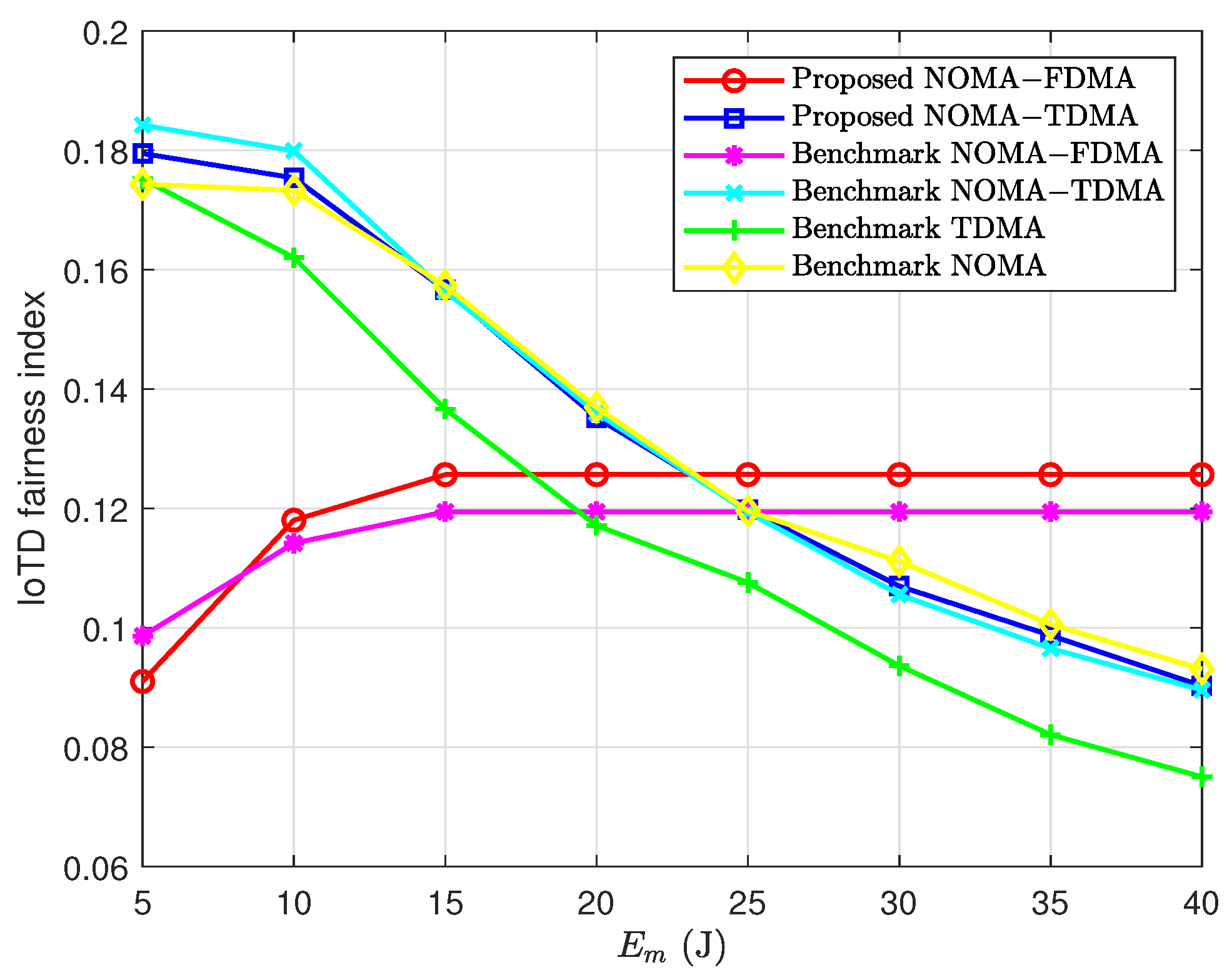
In addition to the sum data performance metric illustrated in the above figures, in the following, we compare the proposed schemes with the benchmark schemes in terms of other performance metrics. First, we consider the IoTD fairness index which is defined as r k 2 K r k 2 [56], where r k is data delivered by IoTD k and K is the total number of IoTDs and can be used to measure the fairness among IoTDs. Note, that a larger value of the IoTD fairness index means that the IoTDs are more fair. Figure 7 compares the IoTD fairness indexes achieved by different schemes. It is seen that as E m increases, the IoTD fairness indexes achieved by the proposed hybrid NOMA-FDMA and the benchmark hybrid NOMA-FDMA increase and then saturate when E m is very large. This indicates that higher consumable energy at the hybrid relays can let the IoTDs with inferior channel conditions obtain more chances to deliver data in these two schemes. It is also seen that with the increase of E m , the IoTD fairness indexes achieved by the proposed hybrid NOMA-TDMA, the benchmark hybrid NOMA-TDMA, the benchmark TDMA and the benchmark NOMA decrease. This means that these schemes allocate more energy resources to the IoTDs with superior channel conditions under higher consumable energy at the hybrid relays. In addition, it is seen that the proposed hybrid NOMA-TDMA provides higher IoTD fairness compared to the proposed hybrid NOMA-FDMA when E m is small, and vice versa. It is also seen that the IoTD fairness indexes achieved by all the schemes are relatively low. This is because all the schemes are greedy at maximizing the sum data delivered by all the IoTDs, and ignore the fairness issue among the IoTDs. Thus, if IoTD fairness is of concern, new schemes with IoTD fairness shall be designed.
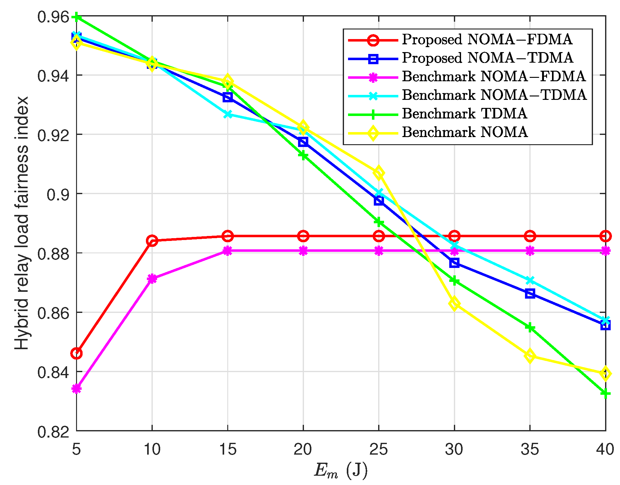
Then, we consider the hybrid relay load fairness index which is defined as min R 1 , m , R 2 , m 2 K min R 1 , m , R 2 , m 2 [57], and can be used to measure the load distributions among hybrid relays. Note, that a larger value of the load fairness index means that the loads of the hybrid relays are more even. Figure 8 compares the hybrid relay load fairness indexes achieved by different schemes. It is seen that the load fairness indexes achieved by all the schemes are relatively high. This indicates that the load distributions among different hybrid relays are relatively even. It is also seen that with the increase of E m , the load fairness indexes achieved by the proposed hybrid NOMA-FDMA and the benchmark hybrid NOMA-FDMA increase and then saturate when E m is very large. This means that higher consumable energy at the hybrid relays can let the hybrid relays with inferior channel conditions collect more data from the IoTDs in these two schemes. In addition, it is seen that as E m increases, the load fairness indexes achieved by the proposed hybrid NOMA-TDMA, the benchmark hybrid NOMA-TDMA, the benchmark TDMA and the benchmark NOMA decrease. This indicates that these schemes are greedy at allocating more energy resources to the hybrid relays with superior channel conditions. It is also seen that the proposed hybrid NOMA-TDMA provides higher load fairness compared to the proposed hybrid NOMA-FDMA when E m is small, and vice versa.
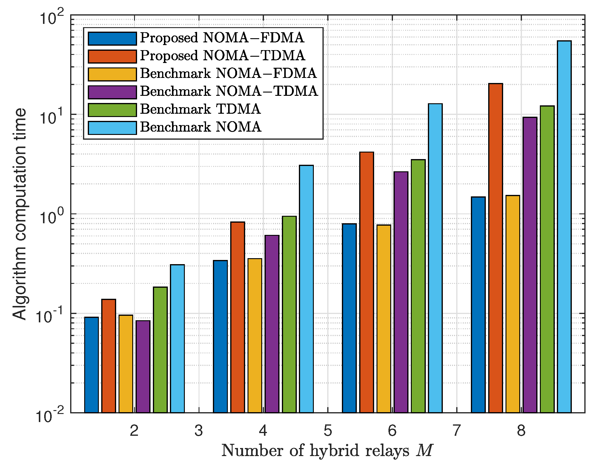
Finally, we consider the algorithm computation time to measure the complexity of the schemes. Figure 9 compares the algorithm computation time achieved by different schemes. It is seen that the algorithm computation time increases as M increases. This is consistent with the time complexity analysis in Section 3 that the time complexity is an increasing function of M. It is also seen that the proposed NOMA-FDMA achieves the lowest algorithm computation time among all the schemes, while the benchmark NOMA achieves the highest algorithm computation time. This means that the proposed NOMA-FDMA is of low complexity while also achieving the highest sum data in some cases as shown in the previous figures. In addition, it is seen that the proposed NOMA-TDMA achieves higher algorithm computation time than the proposed NOMA-FDMA, especially when M is large. Note, that although the proposed NOMA-TDMA has higher time complexity than that of the proposed NOMA-FDMA, it can achieve higher sum data in some cases as discussed above.

5. Conclusions

In this paper, the cooperative resource allocation problems for an uplink wireless powered MC-IoT system consisting of an AP and multiple hybrid relays, each of which serves a group of wireless-powered IoTDs, are investigated. Two cooperative protocols, namely hybrid NOMA-FDMA and hybrid NOMA-TDMA are proposed for coordinating RF-WPT and WIT. The target is maximizing the sum data delivered by all IoTDs, subject to the peak transmit power constraint and the total consumable energy constraint of the hybrid relays. The problem with the hybrid NOMA-FDMA is first decomposed into two subproblems, and then solved by the bisection search, the Lagrange duality method and the Kuhn–Munkres algorithm, while the problem with the hybrid NOMA-TDMA is first convexified by proper variable transformations and then solved by the Lagrange duality method. Simulation results demonstrate the effectiveness of the proposed schemes. It is shown that the proposed hybrid NOMA-FDMA outperforms the proposed hybrid NOMA-TDMA when the peak transmit power limit is large, the total consumable energy limit is small, or the number of IoTDs is small, and the proposed hybrid NOMA-TDMA outperforms the proposed hybrid NOMA-FDMA. It is also shown that either the proposed hybrid NOMA-FDMA or the proposed hybrid NOMA-TDMA outperforms all the benchmark schemes in the existing literature. Note, that IoTD fairness and hybrid relay load fairness are not of concern in this paper while taking them into consideration when designing the cooperative resource allocation schemes in wireless-powered MC-IoT systems can be left as future work.

Author Contributions

Conceptualization, D.X.; methodology, X.C. and D.X.; software, X.C.; validation, X.C., D.X. and H.Z.; formal analysis, X.C.; investigation, X.C.; resources, X.C.; data curation, X.C.; writing—original draft preparation, X.C.; writing—review and editing, D.X.; visualization, X.C.; supervision, D.X. and H.Z.; project administration, D.X. and H.Z.; funding acquisition, H.Z. All authors have read and agreed to the published version of the manuscript.

Funding

This research was funded by the National Natural Science Foundation of China grant number 92067201, and the Jiangsu Provincial Key Research and Development Program grant number BE2020084-1.

Data Availability Statement

Data are contained within the article.

Conflicts of Interest

The authors declare no conflict of interest.

Appendix A

Proof of Proposition 1. 
Suppose that the optimal solution satisfies the constraint in (10) with inequality. Then, the b m , n , k with α m , n = 1 can be increased such that the constraint in (10) is satisfied with equality, and R 1 , m in (1) will be increased. In this case, the objective function value may be increased due to the increase of R 1 , m . Thus, the constraint in (10) can be satisfied at equality by the optimal solution. Then based on this and the constraint in (5), it can be easily obtained that b m , n , k = τ 1 , m ξ m , k p m , n g m , n , k τ 2 , m , m , n , k .  □

Appendix B

Proof of Proposition 2. 
Suppose that τ 1 * , τ 2 * ,   τ 3 * , α * , p * ,   b * and q * is the optimal solution, where p m , n * < P m is satisfied for given m and n. Then, construct a solution τ 1 , τ 2 ,   τ 3 , α , p ,   b and q , where τ 1 = τ 1 * ,   τ 2 = τ 2 * , τ 3 = τ 3 * ,   α = α * , p = p * ,   b = b * and q = q * , except that p m , n = P m and τ 1 , m = p m , n * τ 1 , m * P m . It is easily seen that τ 1 , τ 2 ,   τ 3 , α , p ,   b and q satisfies all the constraints and its objective function value is equal to that of τ 1 * ,   τ 2 * , τ 3 * , α * ,   p * ,   b * and q * . Therefore, the optimal solution satisfies p m , n = P m , m , n .  □

Appendix C

Proof of Proposition 3. 
Suppose that τ 1 , m * , τ 2 , m * , τ 3 , m * and u m , n * is the optimal solution that satisfies the constraints in (38) and (39) with inequality. Then, we can construct a solution τ 1 , m , τ 2 , m , τ 3 , m and u m , n , where τ 2 , m = τ 2 , m * and τ 3 , m = τ 3 , m * . The values of τ 1 , m < τ 1 , m * and u m , n < u m , n * are determined such that the constraints in (38) and (39) are satisfied with equality, respectively. Thus, τ 1 , m P m + u m , n < τ 1 , m * P m + u m , n * and all constraints are still satisfied by τ 1 , m , τ 2 , m ,   τ 3 , m and u m , n . This contradicts with the assumption that τ 1 , m * , τ 2 , m * , τ 3 , m * and u m , n * is the optimal solution. □

Appendix D

Proof of Proposition 5. 
Suppose that the optimal solution satisfies the constraint in (63) with inequality. Then, if we increase the value of e m in the optimal solution such that the constraint in (63) is satisfied with equality, all the constraints are still satisfied and the objective function value is unchanged compared to the optimal solution. Therefore, the constraint in (63) can be satisfied at equality by the optimal solution. □

Appendix E

Proof of Proposition 6. 
From (83), the following equality holds:
N + μ + ν P m j K m π j ξ m , j n = 1 N g m , n , j i K m ξ m , i n = 1 N g m , n , i = μ τ 2 , m h m , n , k τ 2 , m σ 2 + i K m e m , n , i h m , n , i ln 2 π k + ψ k , k .
Since the left hand side of the above equality is independent of k , the following equality holds for any x y :
μ τ 2 , m h m , n , x τ 2 , m σ 2 + i K m e m , n , i h m , n , i ln 2 π x + ψ x = μ τ 2 , m h m , n , y τ 2 , m σ 2 + i K m e m , n , i h m , n , i ln 2 π y + ψ y .
Suppose that there are two arbitrary x and y that e m , n , x > 0 and e m , n , y > 0 . From (84), we have ψ x = ψ y = 0 . Applying this to (A2), the following equality holds for x y :
μ τ 2 , m h m , n , x τ 2 , m σ 2 + i K m e m , n , i h m , n , i ln 2 π x = μ τ 2 , m h m , n , y τ 2 , m σ 2 + i K m e m , n , i h m , n , i ln 2 π y .
Since π x and π y are constant in the problem in (82), and furthermore h m , n , x and h m , n , y are independent random variables, the probability of satisfying the equality in (A3) is zero. Thus, at most one e m , n , k for given m and n is positive.
Suppose that e m , n , k * > 0 with ψ k * = 0 and e m , n , k = 0 , k k * . Then, from (A1), the e m , n , k * in (87) can be easily obtained. Since e m , n , k * > 0 , ψ k * = 0 and e m , n , k = 0 , ψ k 0 , k k * , from (A1), it follows that
N + μ + ν P m j K m π j ξ m , j n = 1 N g m , n , j i K m ξ m , i n = 1 N g m , n , i = μ τ 2 , m h m , n , k * τ 2 , m σ 2 + e m , n , k * h m , n , k * ln 2 π k * ,
N + μ + ν P m j K m π j ξ m , j n = 1 N g m , n , j i K m ξ m , i n = 1 N g m , n , i μ τ 2 , m h m , n , k τ 2 , m σ 2 + e m , n , k * h m , n , k * ln 2 π k ,
from which, it can obtain the following inequality given by
1 h m , n , k * N + μ + ν P m j K m π j ξ m , j n = 1 N g m , n , j i K m ξ m , i n = 1 N g m , n , i + π k * 1 h m , n , k N + μ + ν P m j K m π j ξ m , j n = 1 N g m , n , j i K m ξ m , i n = 1 N g m , n , i + π k .
Thus, k * can be obtained as given by (86).
This completes the proof. □

References

  1. Ma, D.; Lan, G.; Hassan, M.; Hu, W.; Das, S.K. Sensing, computing, and communications for energy harvesting IoTs: A survey. IEEE Commun. Surv. Tutor. 2020, 22, 1222–1250. [Google Scholar] [CrossRef]
  2. Xu, D.; Zhao, H.; Zhu, H. Resource Allocation for Secure Short Packet Communications in Wireless Powered IoT Networks. IEEE Trans. Veh. Technol. 2023, 72, 11000–11005. [Google Scholar] [CrossRef]
  3. Clerckx, B.; Kim, J.; Choi, K.W.; Kim, D.I. Foundations of wireless information and power transfer: Theory, prototypes, and experiments. Proc. IEEE 2022, 110, 8–30. [Google Scholar] [CrossRef]
  4. Xu, D.; Zhu, H. Outage minimized resource allocation for multiuser OFDM systems with SWIPT. IEEE Access 2019, 7, 79714–79725. [Google Scholar] [CrossRef]
  5. Kumar, D.; López, O.L.A.; Joshi, S.K.; Tölli, A. Latency-Aware Multi-antenna SWIPT System with Battery-Constrained Receivers. IEEE Trans. Wirel. Commun. 2023, 22, 3022–3037. [Google Scholar] [CrossRef]
  6. Ju, H.; Zhang, R. Throughput maximization in wireless powered communication networks. IEEE Trans. Wirel. Commun. 2014, 13, 418–428. [Google Scholar] [CrossRef]
  7. Xu, D. Joint Optimal Data Collection Scheduling and Time Allocation in Full-Duplex WP-IoT Networks. IEEE Trans. Veh. Technol. 2023, 72, 10994–10999. [Google Scholar] [CrossRef]
  8. Chen, H.; Zhai, C.; Li, Y.; Vucetic, B. Cooperative strategies for wireless-powered communications: An overview. IEEE Wirel. Commun. 2018, 25, 112–119. [Google Scholar] [CrossRef]
  9. Luo, S.; Yang, G.; Teh, K.C. Throughput of wireless-powered relaying systems with buffer-aided hybrid relay. IEEE Trans. Wirel. Commun. 2016, 15, 4790–4801. [Google Scholar] [CrossRef]
  10. Iqbal, A.; Kim, Y.; Lee, T.J. Access Mechanism in Wireless Powered Communication Networks With Harvesting Access Point. IEEE Access 2018, 6, 37556–37567. [Google Scholar] [CrossRef]
  11. Hu, G.; Cai, Y. Energy-Accumulation-Based Power-Beacon-Assisted WPCN: Time Allocation and Scheduling Schemes. IEEE Commun. Lett. 2019, 23, 1510–1514. [Google Scholar] [CrossRef]
  12. Kumar, P.; Dhaka, K. Performance of Wireless Powered DF Relay System Under Nakagami-m Fading: Relay Assists Energy-Constrained Source. IEEE Syst. J. 2019, 14, 2497–2507. [Google Scholar] [CrossRef]
  13. Shang, X.; Yin, H.; Wang, Y.; Li, M.; Wang, Y. Secure multiuser scheduling for hybrid relay-assisted wireless powered cooperative communication networks with full-duplex destination-based jamming. IEEE Access 2021, 9, 49774–49787. [Google Scholar] [CrossRef]
  14. Wu, M.; Song, Q.; Guo, L.; Jamalipour, A. Charge-then-cooperate: Secure resource allocation for wireless-powered relay networks with wireless energy transfer. IEEE Trans. Veh. Technol. 2021, 70, 5088–5093. [Google Scholar] [CrossRef]
  15. He, Z.; Ji, Y.; Wang, K.; Xu, W.; Shen, H.; Wang, N.; You, X. Energy Minimization for UAV-Enabled Wireless Power Transfer and Relay Networks. IEEE Internet Things J. 2023, 10, 19141–19152. [Google Scholar] [CrossRef]
  16. Nasir, A.A.; Zhou, X.; Durrani, S.; Kennedy, R.A. Relaying protocols for wireless energy harvesting and information processing. IEEE Trans. Wirel. Commun. 2013, 12, 3622–3636. [Google Scholar] [CrossRef]
  17. Zhao, N.; Hu, F.; Li, Z.; Gao, Y. Simultaneous wireless information and power transfer strategies in relaying network with direct link to maximize throughput. IEEE Trans. Veh. Technol. 2018, 67, 8514–8524. [Google Scholar] [CrossRef]
  18. Asiedu, D.K.P.; Lee, H.; Lee, K.J. Simultaneous Wireless Information and Power Transfer for Decode-and-Forward Multihop Relay Systems in Energy-Constrained IoT Networks. IEEE Internet Things J. 2019, 6, 9413–9426. [Google Scholar] [CrossRef]
  19. Zeng, F.; Xiao, X.; Xiao, Z.; Sun, J.; Bai, J.; Havyarimana, V.; Jiang, H. Throughput Maximization for Two-Way Buffer-Aided and Energy-Harvesting Enabled Multi-Relay Networks. IEEE Access 2019, 7, 157972–157986. [Google Scholar] [CrossRef]
  20. Ramezani, P.; Zeng, Y.; Jamalipour, A. Optimal resource allocation for multiuser Internet of Things network with single wireless-powered relay. IEEE Internet Things J. 2019, 6, 3132–3142. [Google Scholar] [CrossRef]
  21. Gu, Q.; Wang, G.; Fan, R.; Zhang, N.; Jiang, H.; Zhong, Z. Optimal Resource Allocation in Wireless Powered Relay Networks with Nonlinear Energy Harvesters. IEEE Wirel. Commun. Lett. 2020, 9, 371–375. [Google Scholar] [CrossRef]
  22. Huang, S.Y.; Liu, K.H. Relay Selection for Energy Harvesting Relays With Energy Prioritization and Inter-Relay Charging. IEEE Trans. Veh. Technol. 2022, 71, 10646–10655. [Google Scholar] [CrossRef]
  23. Xu, F.; Yang, H.C.; Alouini, M.S. Ultra-Green Relay Transmission with Wireless Power Transfer for Advanced IoT: Session-Specific Analysis and Optimization. IEEE Internet Things J. 2023, 10, 15553–15562. [Google Scholar] [CrossRef]
  24. Zheng, Y.; Hu, J.; Yang, K. SWIPT aided Cooperative Communications with Energy Harvesting based Selective-Decode-and-Forward Protocol: Benefiting from Channel Aging Effect. IEEE Trans. Green Commun. Netw. 2023, 7, 1192–1204. [Google Scholar] [CrossRef]
  25. Chen, H.; Li, Y.; Rebelatto, J.L.; Uchoa-Filho, B.F.; Vucetic, B. Harvest-then-cooperate: Wireless-powered cooperative communications. IEEE Trans. Signal Process. 2015, 63, 1700–1711. [Google Scholar] [CrossRef]
  26. Chen, Y.; Shi, R.; Feng, W.; Ge, N. AF relaying with energy harvesting source and relay. IEEE Trans. Veh. Technol. 2017, 66, 874–879. [Google Scholar] [CrossRef]
  27. Zhan, J.; Liu, Y.; Tang, X.; Chen, Q. Relaying protocols for buffer-aided energy harvesting wireless cooperative networks. IET Netw. 2018, 7, 109–118. [Google Scholar] [CrossRef]
  28. Li, S.; Hu, F.; Xu, Z.; Mao, Z.; Ling, Z.; Liu, H. Joint power allocation in classified WBANs with wireless information and power transfer. IEEE Internet Things J. 2021, 8, 989–1000. [Google Scholar] [CrossRef]
  29. Xu, D.; Zhu, H. Sum-rate maximization of wireless powered primary users for cooperative CRNs: NOMA or TDMA at cognitive users? IEEE Trans. Commun. 2021, 69, 4862–4876. [Google Scholar] [CrossRef]
  30. Liu, Y.; Zhang, S.; Mu, X.; Ding, Z.; Schober, R.; Al-Dhahir, N.; Hossain, E.; Shen, X. Evolution of NOMA toward next generation multiple access (NGMA) for 6G. IEEE J. Sel. Areas Commun. 2022, 40, 1037–1071. [Google Scholar] [CrossRef]
  31. Do, N.T.; Da Costa, D.B.; Duong, T.Q.; An, B. A BNBF user selection scheme for NOMA-based cooperative relaying systems with SWIPT. IEEE Commun. Lett. 2017, 21, 664–667. [Google Scholar] [CrossRef]
  32. Tran, H.Q.; Nguyen, T.T.; Phan, C.V.; Vien, Q.T. Power-splitting relaying protocol for wireless energy harvesting and information processing in NOMA systems. IET Commun. 2019, 13, 2132–2140. [Google Scholar] [CrossRef]
  33. Li, T.; Zhang, H.; Zhou, X.; Yuan, D. NOMA-Enabled Layered Video Multicast in Wireless-Powered Relay Systems. IEEE Commun. Lett. 2019, 23, 2118–2121. [Google Scholar] [CrossRef]
  34. Zhang, X.; Wang, F. Resource allocation for wireless power transmission over full-duplex OFDMA/NOMA mobile wireless networks. IEEE J. Sel. Areas Commun. 2019, 37, 327–344. [Google Scholar] [CrossRef]
  35. Lan, X.; Zhang, Y.; Chen, Q.; Cai, L. Energy Efficient Buffer-aided Transmission Scheme in Wireless Powered Cooperative NOMA Relay Network. IEEE Trans. Commun. 2020, 68, 1432–1447. [Google Scholar] [CrossRef]
  36. Zhai, C.; Li, Y.; Wang, X.; Yu, Z. Nonorthogonal Multiple Access With Energy Harvesting-Based Alternate Relaying. IEEE Syst. J. 2022, 16, 327–338. [Google Scholar] [CrossRef]
  37. Agrawal, K.; Prakriya, S.; Flanagan, M.F. TS-based SWIPT in Full-duplex Relayed NOMA with Intelligent Relay Battery Management. IEEE Trans. Commun. 2023, 71, 5137–5151. [Google Scholar] [CrossRef]
  38. Zeng, M.; Yadav, A.; Dobre, O.A.; Poor, H.V. Energy-efficient joint user-RB association and power allocation for uplink hybrid NOMA-OMA. IEEE Internet Things J. 2019, 6, 5119–5131. [Google Scholar] [CrossRef]
  39. Shi, J.; Yu, W.; Ni, Q.; Liang, W.; Li, Z.; Xiao, P. Energy efficient resource allocation in hybrid non-orthogonal multiple access systems. IEEE Trans. Commun. 2019, 67, 3496–3511. [Google Scholar] [CrossRef]
  40. Wei, X.; Al-Obiedollah, H.; Cumanan, K.; Wang, W.; Ding, Z.; Dobre, O.A. Spectral-energy efficiency trade-off based design for hybrid TDMA-NOMA system. IEEE Trans. Veh. Technol. 2022, 71, 3377–3382. [Google Scholar] [CrossRef]
  41. Wei, X.; Al-Obiedollah, H.; Cumanan, K.; Ding, Z.; Dobre, O.A. Energy efficiency maximization for hybrid TDMA-NOMA system with opportunistic time assignment. IEEE Trans. Veh. Technol. 2022, 71, 8561–8573. [Google Scholar] [CrossRef]
  42. Chaieb, C.; Abdelkefi, F.; Ajib, W. Deep reinforcement learning for resource allocation in multi-band and hybrid OMA-NOMA wireless networks. IEEE Trans. Commun. 2023, 71, 187–198. [Google Scholar] [CrossRef]
  43. Obaid, A.; Fernando, X.; Jaseemuddin, M. A mobility-aware cluster-based MAC protocol for radio-frequency energy harvesting cognitive wireless sensor networks. IET Wirel. Sens. Syst. 2021, 11, 206–218. [Google Scholar] [CrossRef]
  44. Lu, X.; Wang, P.; Niyato, D.; Kim, D.I.; Han, Z. Wireless networks with RF energy harvesting: A contemporary survey. IEEE Commun. Surv. Tutor. 2015, 17, 757–789. [Google Scholar] [CrossRef]
  45. Sudevalayam, S.; Kulkarni, P. Energy harvesting sensor nodes: Survey and implications. IEEE Commun. Surv. Tutor. 2011, 13, 443–461. [Google Scholar] [CrossRef]
  46. Wu, Q.; Chen, W.; Ng, D.W.K.; Schober, R. Spectral and energy-efficient wireless powered IoT networks: NOMA or TDMA? IEEE Trans. Veh. Technol. 2018, 67, 6663–6667. [Google Scholar] [CrossRef]
  47. Zou, Y.; Zhu, J.; Jiang, X. Joint Power Splitting and Relay Selection in Energy-Harvesting Communications for IoT Networks. IEEE Internet Things J. 2020, 7, 584–597. [Google Scholar] [CrossRef]
  48. Boyd, S.; Vandenberghe, L. Convex Optimization; Cambridge University Press: Cambridge, UK, 2004. [Google Scholar]
  49. Corless, R.M.; Gonnet, G.H.; Hare, D.E.; Jeffrey, D.J.; Knuth, D.E. On the LambertW function. Adv. Comput. Math. 1996, 5, 329–359. [Google Scholar] [CrossRef]
  50. Kuhn, H.W. The Hungarian method for the assignment problem. Nav. Res. Logist. Q. 1955, 2, 83–97. [Google Scholar] [CrossRef]
  51. Lawler, E.L. Combinatorial Optimization: Networks and Matroids; Courier Corporation: Chelmsford, MA, USA, 2001. [Google Scholar]
  52. Tseng, P. Convergence of a block coordinate descent method for nondifferentiable minimization. J. Optim. Theory Appl. 2001, 109, 475–494. [Google Scholar] [CrossRef]
  53. Xu, D.; Zhu, H. Secure Transmission for SWIPT IoT Systems With Full-Duplex IoT Devices. IEEE Internet Things J. 2019, 6, 10915–10933. [Google Scholar] [CrossRef]
  54. Bland, R.G.; Goldfarb, D.; Todd, M.J. The ellipsoid method: A survey. Oper. Res. 1981, 29, 1039–1091. [Google Scholar] [CrossRef]
  55. Yang, Z.; Xu, W.; Xu, H.; Shi, J.; Chen, M. Energy efficient non-orthogonal multiple access for machine-to-machine communications. IEEE Commun. Lett. 2017, 21, 817–820. [Google Scholar] [CrossRef]
  56. Huaizhou, S.; Prasad, R.V.; Onur, E.; Niemegeers, I. Fairness in wireless networks: Issues, measures and challenges. IEEE Commun. Surv. Tutor. 2014, 16, 5–24. [Google Scholar] [CrossRef]
  57. Wen, Y.F.; Shen, J.C. Load-balancing metrics: Comparison for infrastructure-based wireless networks. Comput. Electr. Eng. 2014, 40, 730–753. [Google Scholar] [CrossRef]
Figure 1. System model.
Electronics 13 00099 g001
Figure 2. Frame structure of the hybrid NOMA-FDMA.
Electronics 13 00099 g002
Figure 3. Frame structure of the hybrid NOMA-TDMA.
Electronics 13 00099 g003
Figure 4. Sum data versus the total consumable energy limit E m .
Electronics 13 00099 g004
Figure 5. Sum data versus the peak transmit power limit P m .
Electronics 13 00099 g005
Figure 6. Sum data versus the number of IoTDs K ( P m = 10 W).
Electronics 13 00099 g006
Figure 7. Performance comparison in terms of IoTD fairness index.
Electronics 13 00099 g007
Figure 8. Performance comparison in terms of hybrid relay load fairness index.
Electronics 13 00099 g008
Figure 9. Performance comparison in terms of algorithm computation time.
Electronics 13 00099 g009
Disclaimer/Publisher’s Note: The statements, opinions and data contained in all publications are solely those of the individual author(s) and contributor(s) and not of MDPI and/or the editor(s). MDPI and/or the editor(s) disclaim responsibility for any injury to people or property resulting from any ideas, methods, instructions or products referred to in the content.

