
Optimization Study of Cooling Channel for the Oil Cooling Air Gap Armature in a High-Temperature Superconducting Motor

 , and
, and
Abstract
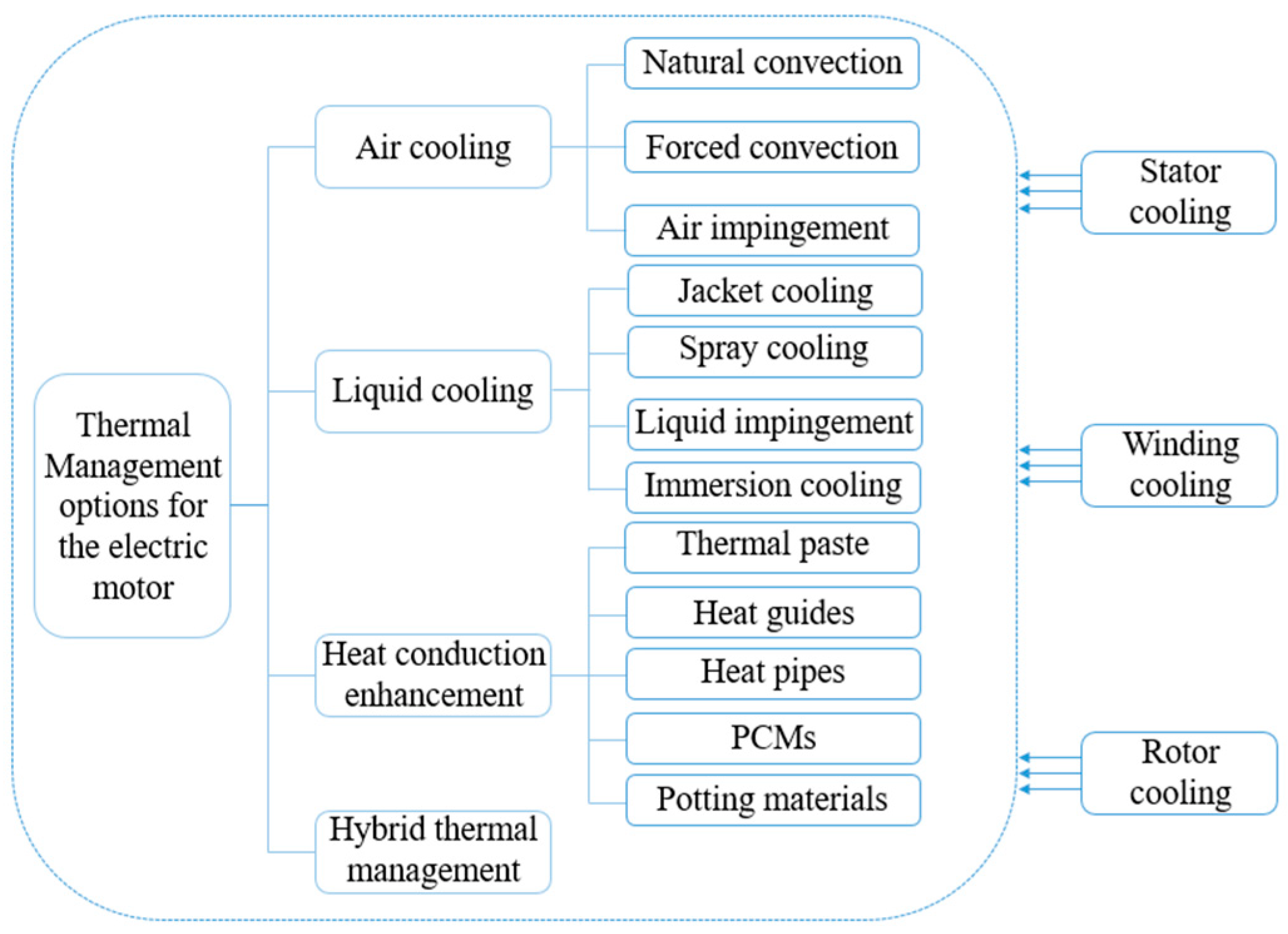
:1. Introduction
2. Methods
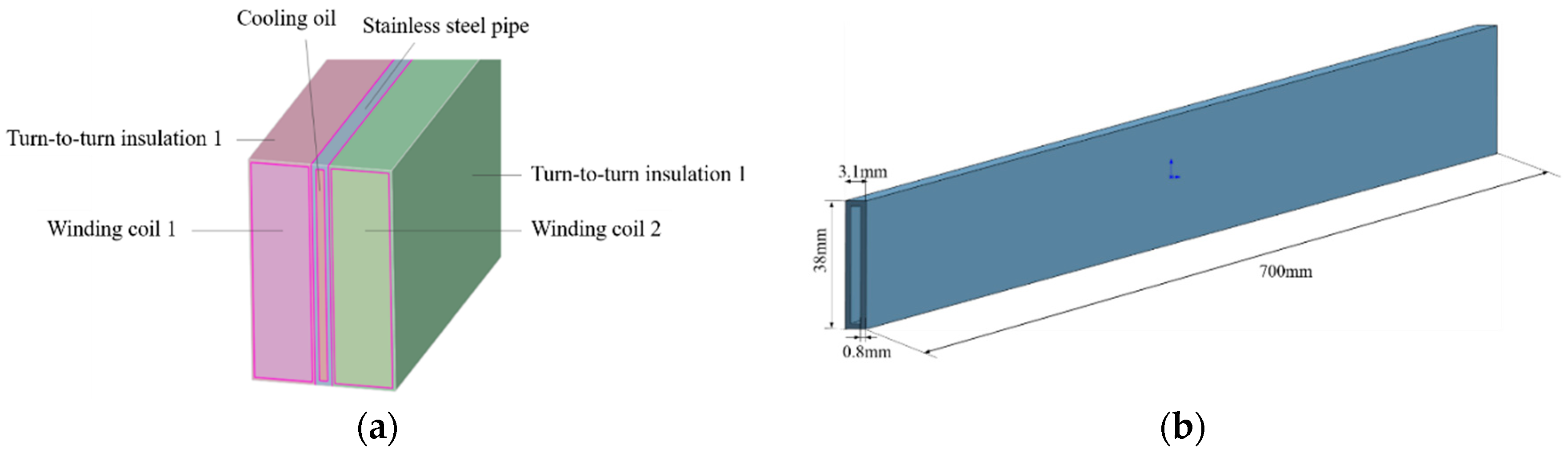
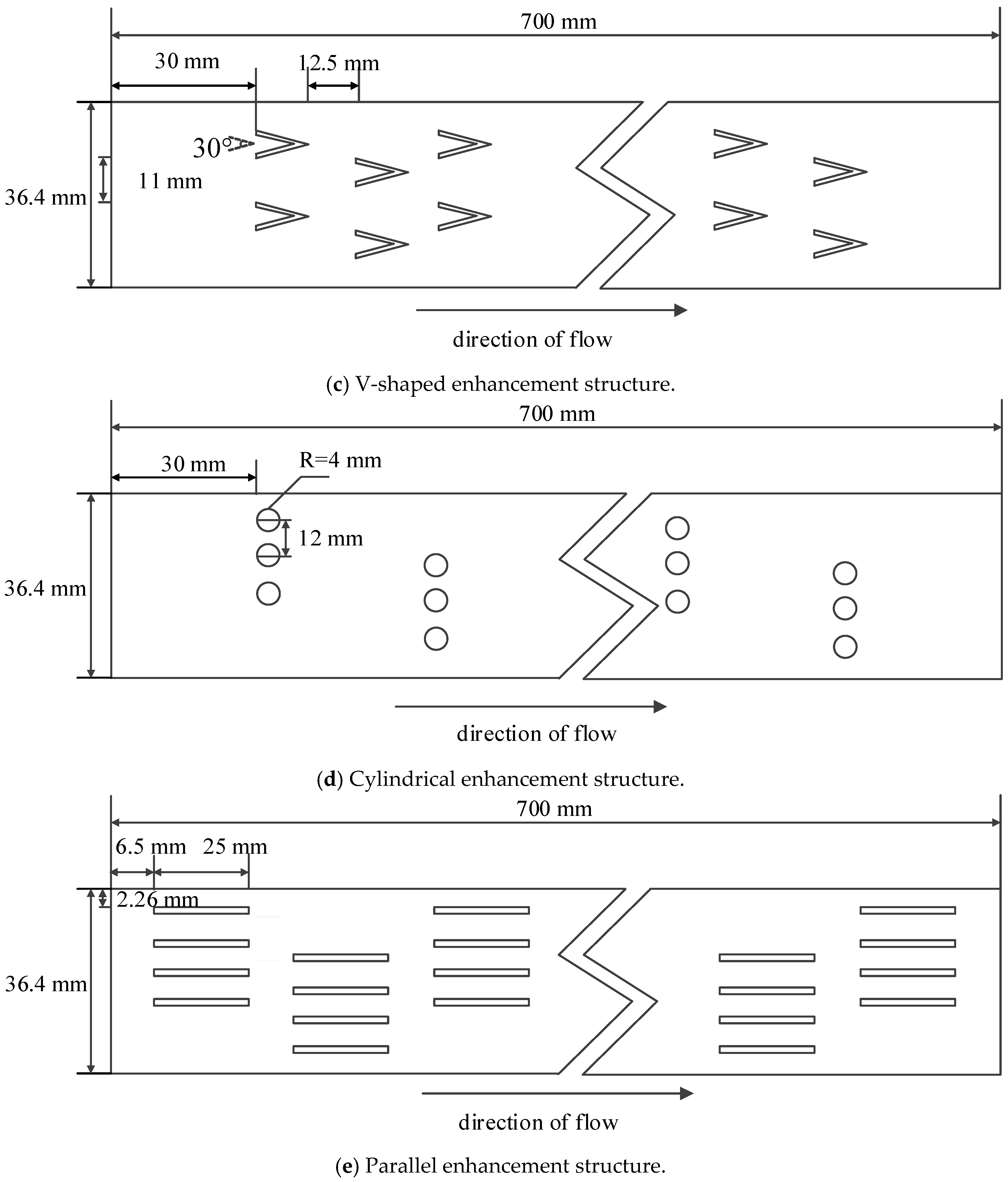
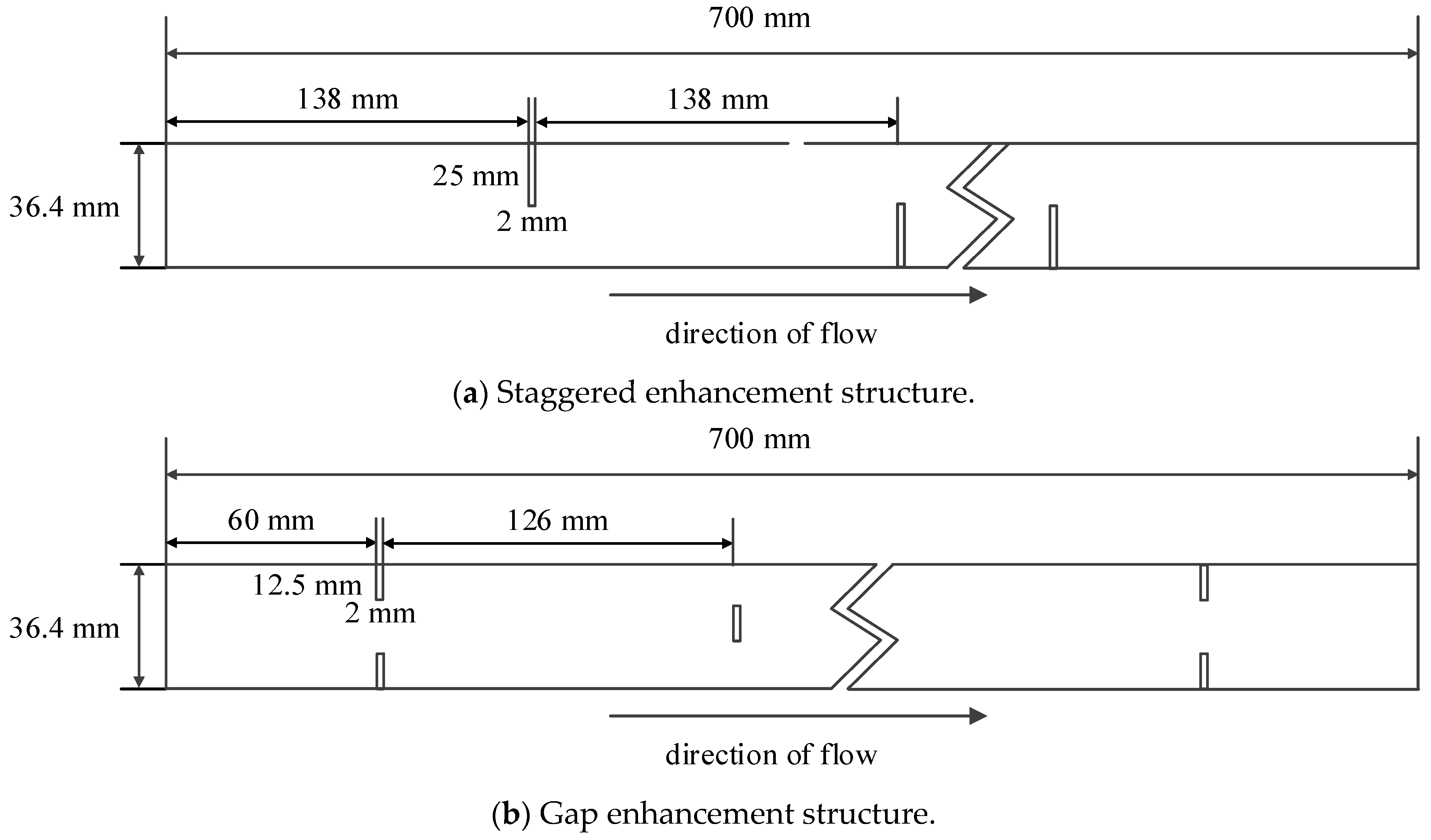
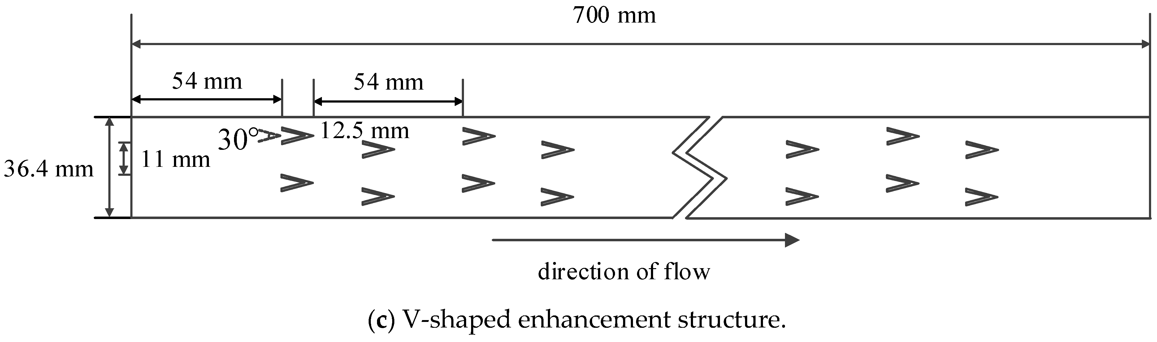
2.1. Geometries of the Oil Cooling Channel
2.2. Evaluation Indicators
- (1)
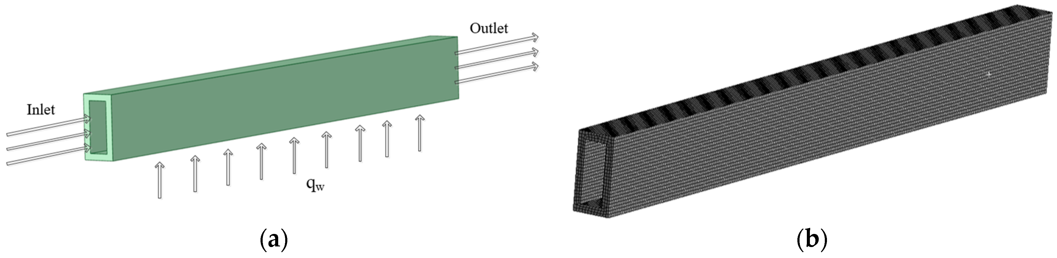
- The Nusselt number is calculated by:where λ is the thermal conductivity of the oil and is the hydraulic diameter of the cooling channel, calculated by:where Ac is the cross-sectional area of the pipe, P is the wetted perimeter, and h is the convective heat transfer coefficient, defined as:where qw is the heat flux of the heated wall surface and is the difference between the average temperature of the wall surface (area average) and the average temperature of the fluid.
- (2)
- Friction factor f is computed as:where is the pressure difference between the inlet and outlet, is the inlet velocity, is the fluid density, and is the pipe length.
- (3)
- The performance evaluation criterion () is calculated as:where and are the Nusselt number and friction factor of the enhancement structure channel, respectively, and and are the Nusselt number and friction factor of the bare pipe, respectively.
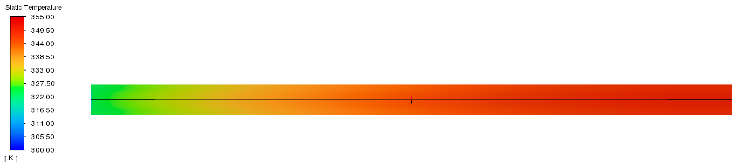
2.3. Model Validation
3. Screening of Five Enhancement Structures
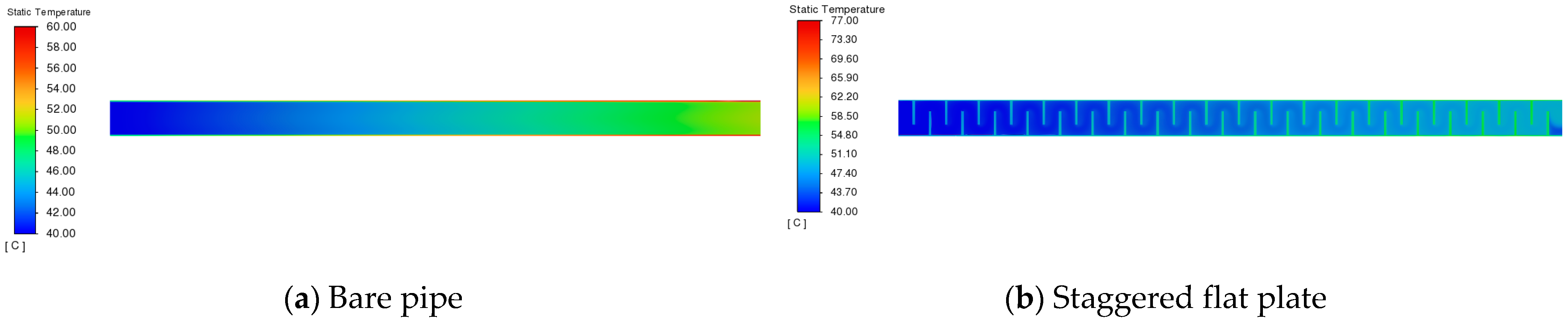
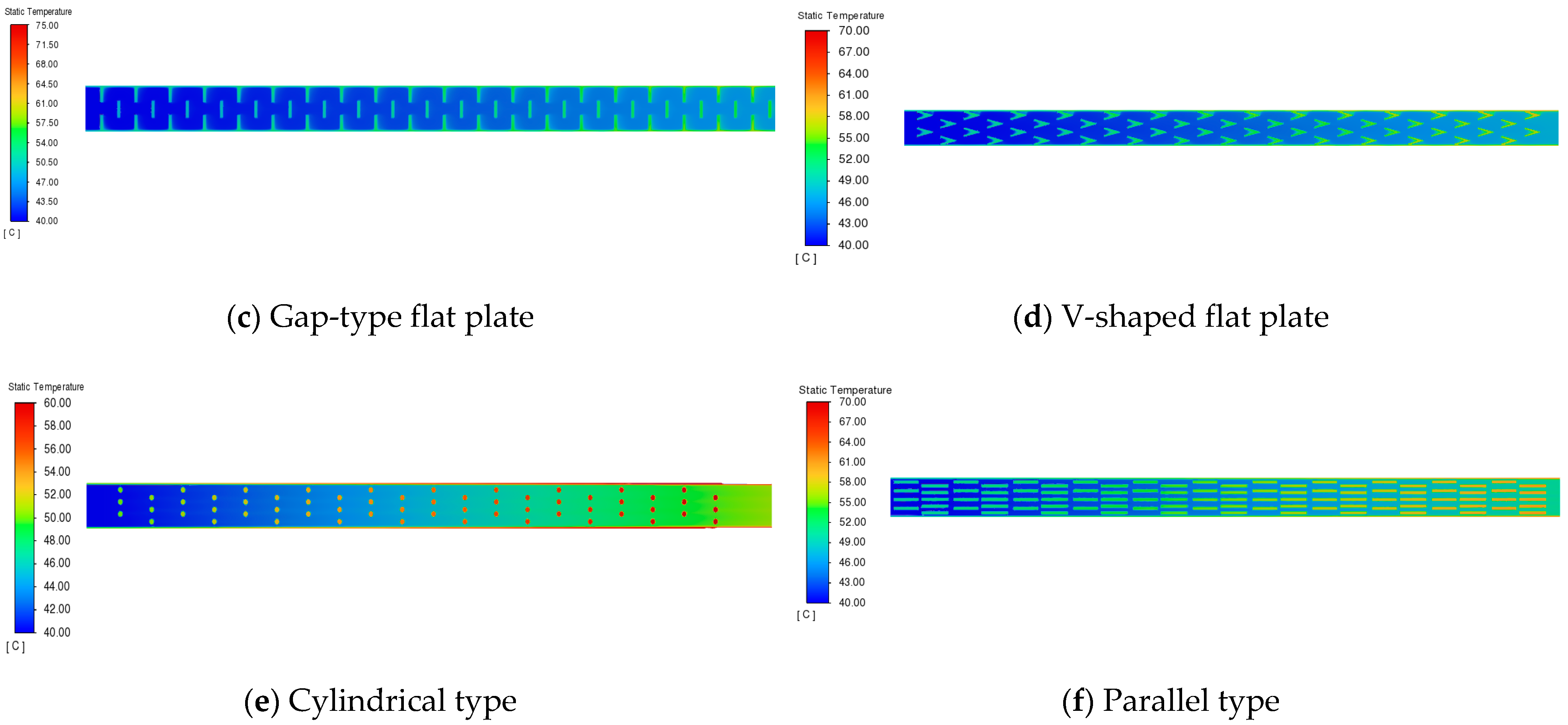
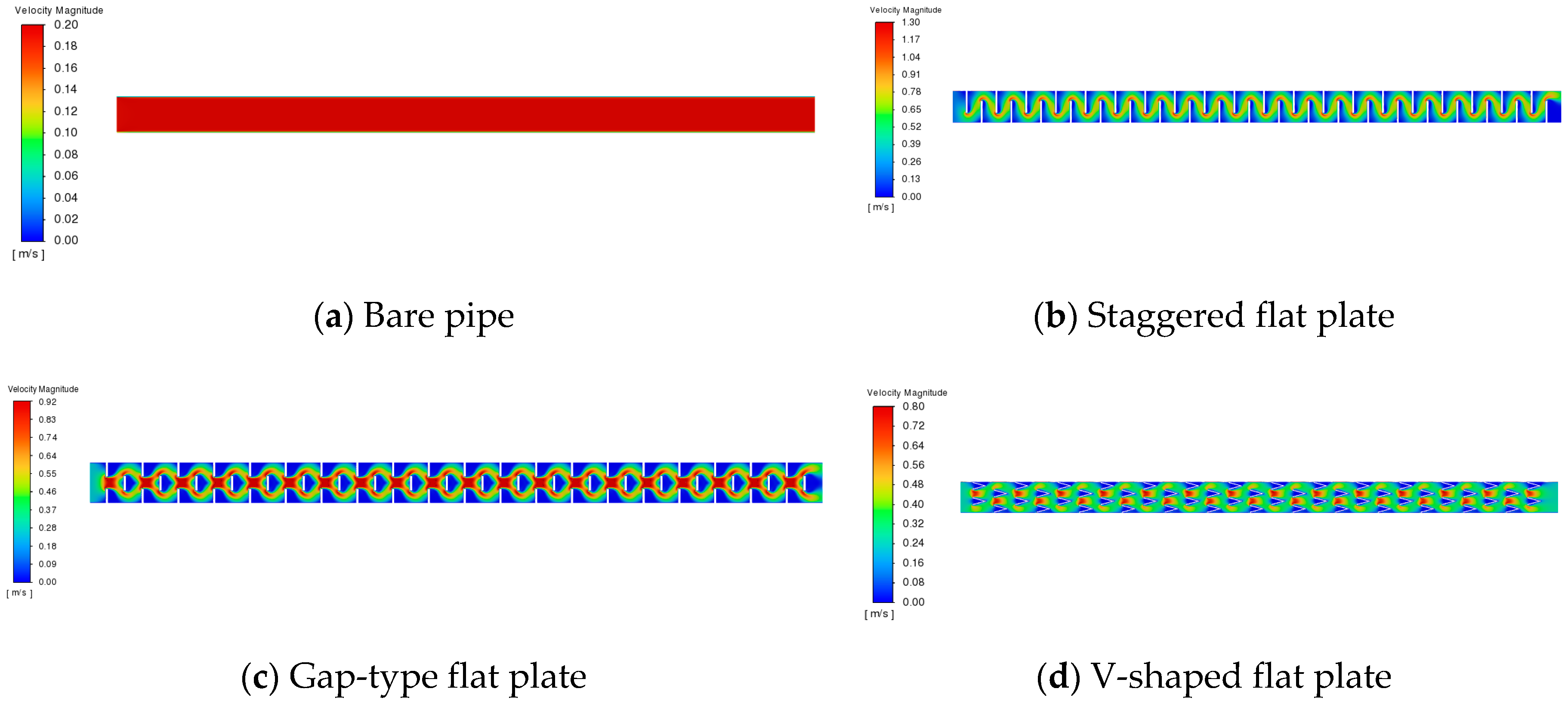
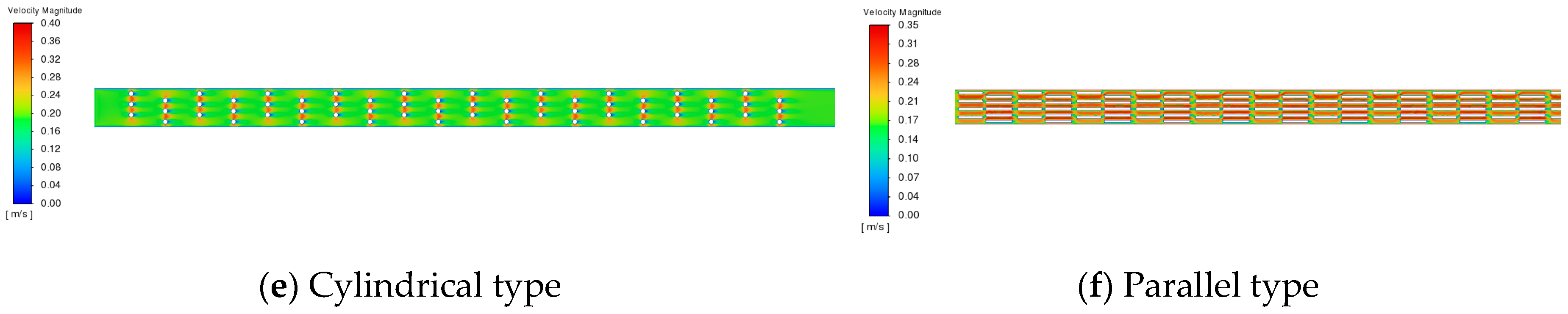
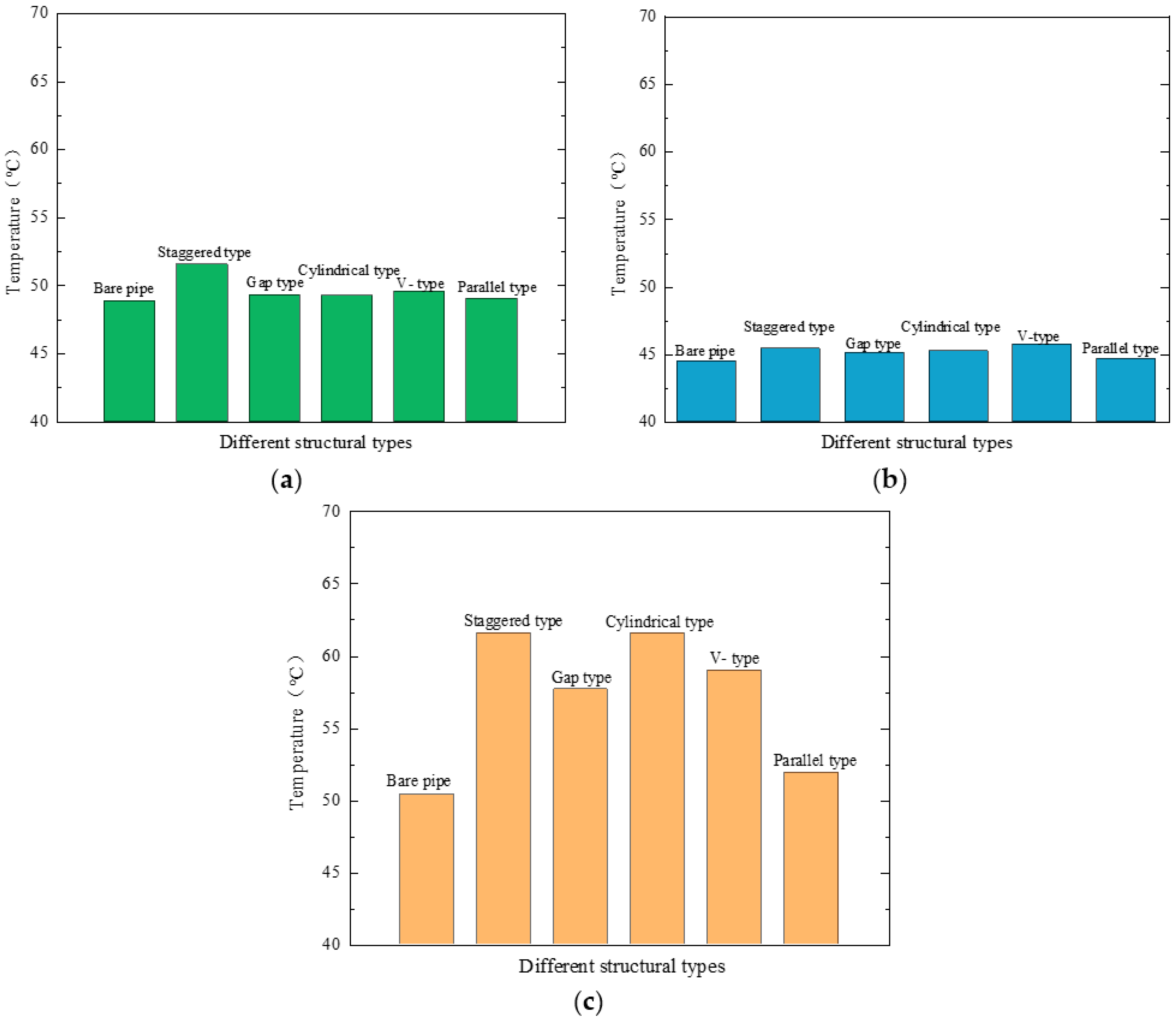
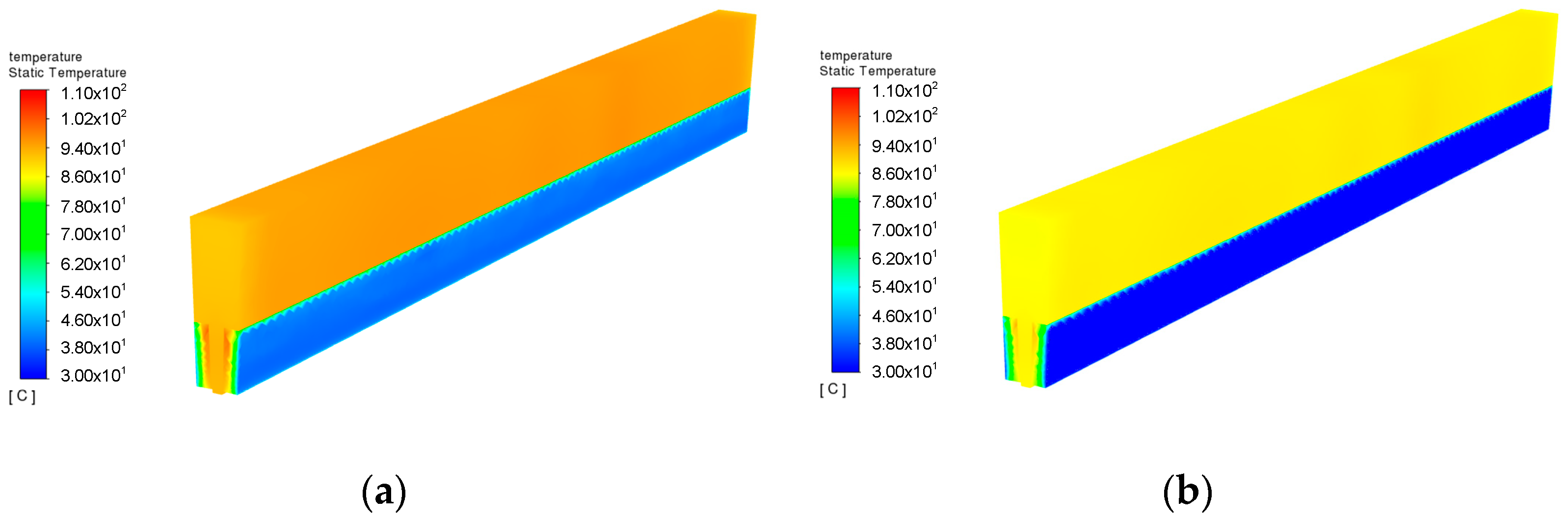
3.1. Velocity and Temperature Distributions of Different Enhancement Structures
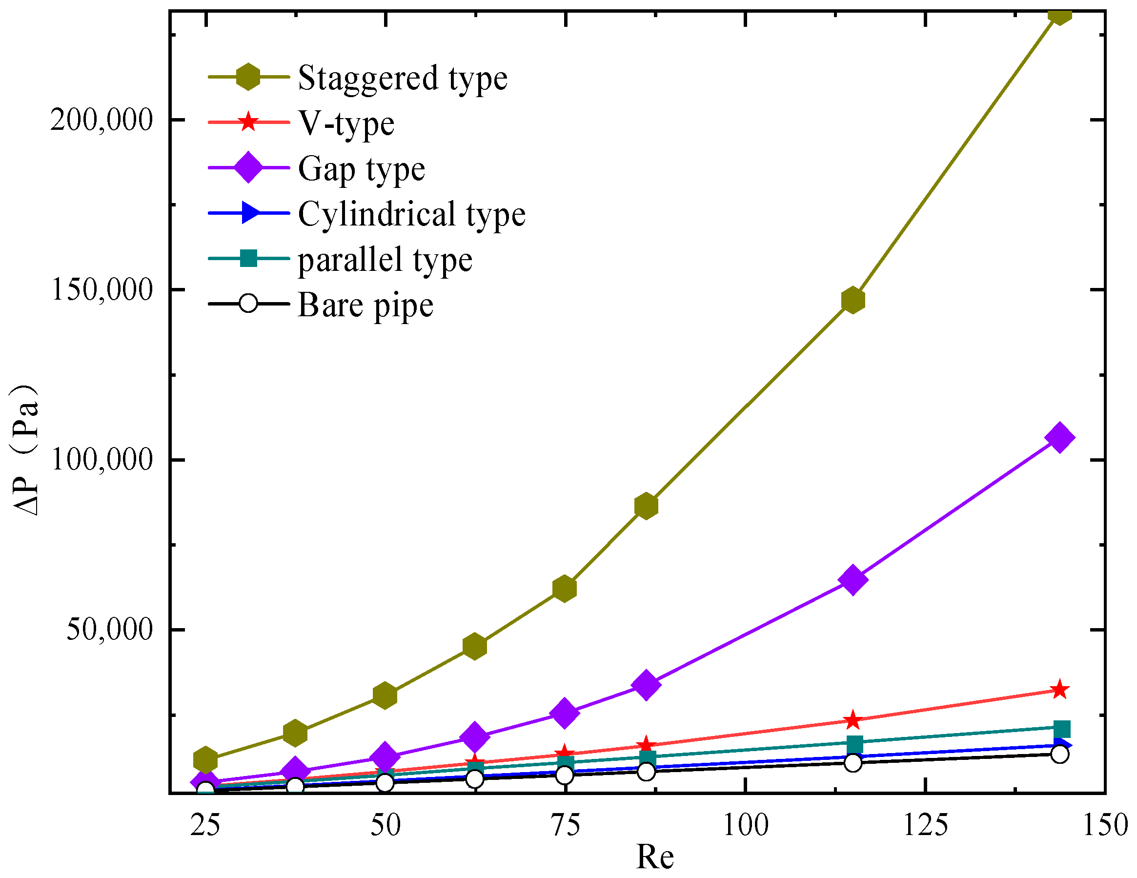
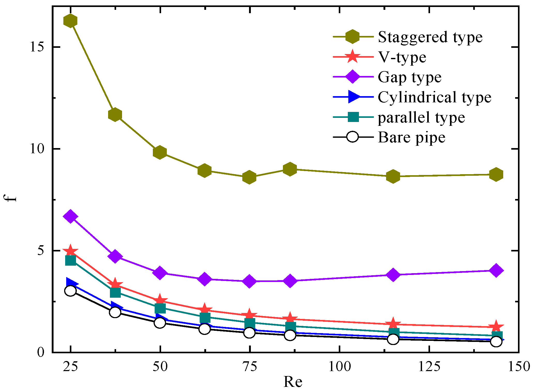
3.2. Effects of Reynolds Number on the Performance of Different Enhancement Structures
3.3. Comprehensive Performance Analysis
4. Analysis of the Optimal Enhancement Structure
4.1. Further Optimization of the Three Enhancement Structures
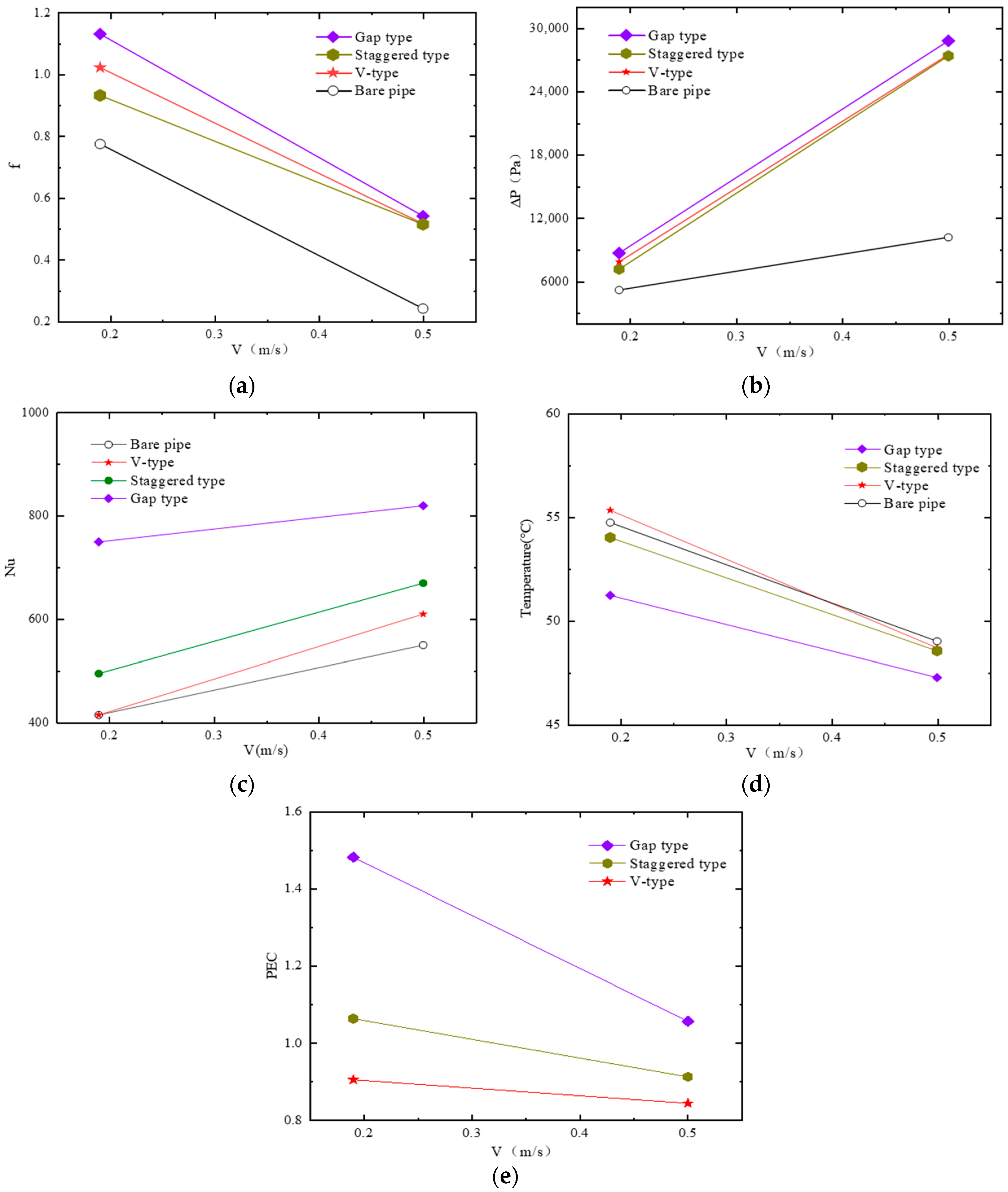
4.2. Performance Analysis of Optimal Structures
5. Conclusions
- (1)
- The five different enhancement structures improved the heat dissipation performance of the oil cooling channel. The fluid temperature near the outlet side was higher than the outlet temperature of the bare pipe. The heat transfer performance of the gap, staggered, and V types was better than that of the cylindrical and parallel types.
- (2)
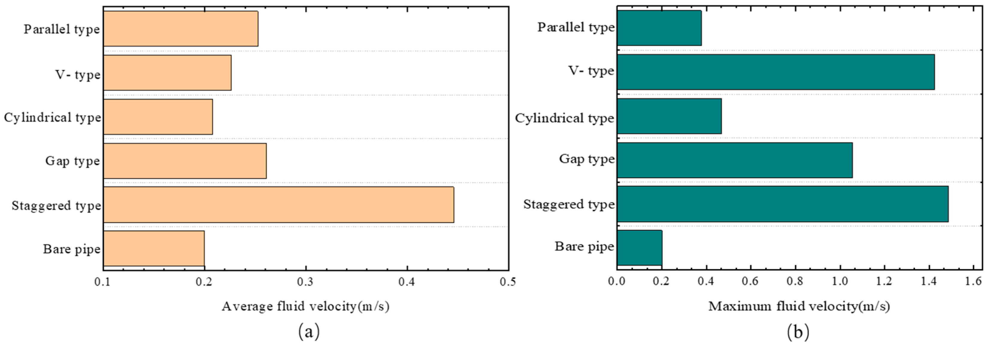
- The addition of the enhancement structures increased the fluid flow velocity in the pipe. The staggered structure had the highest average flow velocity, and the flow velocity changed considerably as it approached the flow velocity of the enhancement structure.
- (3)
- For the three types of enhancement structures with the best heat transfer performance, namely, staggered, gap, and V types, structural optimization was conducted by changing the number of enhancement units in the pipe enhancement structure under the conditions of pressure drop not exceeding 30 kPa at flow rates of 0.19 and 0.5 m/s. A comprehensive evaluation of the three structures showed that at the same flow velocity, the Nusselt number of the gap-type structure was 68% higher than that of the bare pipe. Under the same pump power consumption conditions, the PEC value of the gap-type structure increased by 39% and 63% compared with the PEC values of the staggered and V-type enhancement structures, respectively.
Author Contributions
Funding
Data Availability Statement
Conflicts of Interest
Nomenclature
| λ | thermal conductivity(W/(m·K)) | μ | inlet velocity (m/s) |
| Dh | hydraulic diameter (m) | Subscripts | |
| Ac | cross-sectional area (m2) | Nu0 | Nusselt number of the bare pipe |
| P | wetted perimeter (m) | f0 | the friction factor of the bare pipe |
| h | heat transfer coefficient (W/(m2·K)) | Abbreviation | |
| qw | heat flux (W) | Nu | Nusselt number |
| ΔT | the average temperature difference between the wall surface and the fluid (°C) | PEC | performance evaluation criterion |
| ΔP | the pressure difference between the inlet and outlet (Pa) | f | friction factor |
| Greek | |||
References
- Zhou, Y.; Dong, Q.; Zheng, J. Thermal management of air-core stator for a large-capacity HTS motor. In Proceedings of the 2015 IEEE Electric Ship Technologies Symposium (Ests), Old Town Alexandria, VA, USA, 21–24 June 2015; IEEE: New York, NY, USA, 2015; pp. 109–112. [Google Scholar]
- Li, W.; Ching, T.W.; Chau, K.T.; Lee, C.H.T. A superconducting vernier motor for electric ship propulsion. IEEE Trans. Appl. Supercond. 2017, 28, 17478276. [Google Scholar] [CrossRef]
- Torrey, D.; Parizh, M.; Bray, J.; Stautner, W.; Tapadia, N.; Xu, M.; Wu, A.; Zierer, J. Superconducting synchronous motors for electric ship propulsion. IEEE Trans. Appl. Supercond. 2020, 30, 19521682. [Google Scholar] [CrossRef]
- Schreiner, F.; Liu, Y.; Zhang, Y.; Gyuraki, R.; Noe, M.; Doppelbauer, M. Development of no-insulation racetrack coils wound with 2nd generation HTS tapes for a stator system for wind generators. IEEE Trans. Appl. Supercond. 2020, 30, 19420010. [Google Scholar] [CrossRef]
- Zhou, Y.; Dong, Q.; Niu, X.-J.; Xu, H.; Xiong, Q.; Su, H.; Zheng, J. A pole pair segment of oil-cooling air-core stator for a 2 MW direct-drive high temperature superconducting wind power generator. J. Electr. Eng. Technol. 2021, 16, 3145–3155. [Google Scholar] [CrossRef]
- Weng, F.; Zhang, M.; Lan, T.; Wang, Y.; Yuan, W. Fully superconducting machine for electric aircraft propulsion: Study of AC loss for HTS stator. Supercond. Sci. Technol. 2020, 33, 104002. [Google Scholar] [CrossRef]
- Isfahani, A.H.; Vaez-Zadeh, S. Line start permanent magnet synchronous motors: Challenges and opportunities. Energy 2009, 34, 1755–1763. [Google Scholar] [CrossRef]
- Lu, S.M. A review of high-efficiency motors: Specification, policy, and technology. Renew. Sustain. Energy Rev. 2016, 59, 1–12. [Google Scholar] [CrossRef]
- Han, J.; Dong, J.; Wang, Y.; Wang, C.; Ge, B.; Li, W. Coupled electromagnetic-fluid-thermal analysis for end zone with electric screen in large water-hydrogen-hydrogen cooled turbine generator under different end winding extensions. IEEE Trans. Energy Convers. 2021, 36, 2703–2713. [Google Scholar] [CrossRef]
- Grabowski, M.; Urbaniec, K.; Wernik, J.; Wołosz, K.J. Numerical simulation and experimental verification of heat transfer from a finned housing of an electric motor. Energy Convers. Manag. 2016, 125, 91–96. [Google Scholar] [CrossRef]
- Roffi, M.; Ferreira FJ, T.E.; De Almeida, A.T. Comparison of different cooling fan designs for electric motors. In Proceedings of the 2017 IEEE International Electric Machines and Drives Conference (IEMDC), Miami, FL, USA, 21–24 May 2017; IEEE: New York, NY, USA, 2017; pp. 1–7. [Google Scholar]
- Gilson, G.M.; Pickering, S.J.; Hann, D.B.; Gerada, C. Piezoelectric fan cooling: A novel high reliability electric machine thermal management solution. IEEE Trans. Ind. Electron. 2012, 60, 4841–4851. [Google Scholar] [CrossRef]
- Gai, Y.; Kimiabeigi, M.; Chong, Y.C.; Widmer, J.D.; Deng, X.; Popescu, M.; Goss, J.; Staton, D.A.; Steven, A. Cooling of automotive traction motors: Schemes, examples, and computation methods. IEEE Trans. Ind. Electron. 2018, 66, 1681–1692. [Google Scholar] [CrossRef]
- Fan, X.; Li, D.; Qu, R.; Wang, C.; Fang, H. Water cold plates for efficient cooling: Verified on a permanent-magnet machine with concentrated winding. IEEE Trans. Ind. Electron. 2019, 67, 5325–5336. [Google Scholar] [CrossRef]
- Polikarpova, M. Liquid Cooling Solutions for Rotating Permanent Magnet Synchronous Machines; Lappeenranta University of Technology: Lappeenranta, Finland, 2014. [Google Scholar]
- Kwon, Y.K.; Baik, S.K.; Lee, E.Y.; Lee, J.D.; Kim, J.M.; Kim, Y.C.; Moon, T.S.; Park, H.J.; Kwon, W.S.; Hong, J.P.; et al. Status of HTS motor development for industrial applications at KERI & DOOSAN. IEEE Trans. Appl. Supercond. 2007, 17, 1587–1590. [Google Scholar]
- Schiefer, M.; Doppelbauer, M. Indirect slot cooling for high-power-density machines with concentrated winding. In Proceedings of the 2015 IEEE International Electric Machines & Drives Conference (IEMDC), Coeur d’Alene, ID, USA, 10–13 May 2015; IEEE: New York, NY, USA, 2015; pp. 1820–1825. [Google Scholar]
- Li, Y.; Fan, T.; Sun, W.; Li, Q.; Wen, X. Experimental research on the oil cooling of the end winding of the motor. In Proceedings of the 2016 IEEE Energy Conversion Congress and Exposition (ECCE), Milwaukee, WI, USA, 18–22 September 2016; IEEE: New York, NY, USA, 2016; pp. 1–4. [Google Scholar]
- Zhou, Y.; Xu, H.; Xiong, Q.; Niu, X.-J.; Xie, R.-G. Design, performance analysis, and testing of composite components for the oil-cooling air-core stator of a high temperature superconducting motor. IEEE Trans. Appl. Supercond. 2021, 31, 21053654. [Google Scholar] [CrossRef]
- Han, N.G.; Lee, H.L.; Kim, R.H.; Beom, T.Y.; Kim, Y.K.; Ha, T.W.; Lee, S.W.; Kim, D.K. Thermal analysis of the oil cooling motor according to the churning phenomenon. Appl. Therm. Eng. 2023, 220, 119791. [Google Scholar] [CrossRef]
- Garud, K.S.; Hwang, S.-G.; Han, J.-W.; Lee, M.-Y. Performance characteristics of the direct spray oil cooling system for a driving motor of an electric vehicle. Int. J. Heat Mass Transf. 2022, 196, 123228. [Google Scholar] [CrossRef]
- Park, M.H.; Kim, S.C. Development and validation of lumped parameter thermal network model on rotational oil spray cooled motor for electric vehicles. Appl. Therm. Eng. 2023, 225, 120176. [Google Scholar] [CrossRef]
- Park, J.; An, J.; Han, K.; Choi, H.-S.; Park, I.S. Enhancement of cooling performance in traction motor of electric vehicle using direct slot cooling method. Appl. Therm. Eng. 2022, 217, 119082. [Google Scholar] [CrossRef]
- Semidey, S.A.; Mayor, J.R. Experimentation of an electric machine technology demonstrator incorporating direct winding heat exchangers. IEEE Trans. Ind. Electron. 2014, 61, 5771–5778. [Google Scholar] [CrossRef]
- Wang, X.; Li, B.; Gerada, D.; Huang, K.; Stone, I.; Worrall, S.; Yan, Y. A critical review on thermal management technologies for motors in electric cars. Appl. Therm. Eng. 2022, 201, 117758. [Google Scholar] [CrossRef]
- Guo, F.; Zhang, C. Oil-cooling method of the permanent magnet synchronous motor for electric vehicle. Energies 2019, 12, 2984. [Google Scholar] [CrossRef]
- Zhang, F.; Gerada, D.; Xu, Z.; Zhang, X.; Zhang, H.; Gerada, C.; Zhu, M.; Xia, L.; Zhang, W.; Degano, M. Improved thermal modeling and experimental validation of oil-flooded high-performance machines with slot-channel cooling. IEEE Trans. Transp. Electrif. 2021, 8, 312–324. [Google Scholar] [CrossRef]
- Chang, J.; Fan, Y.; Wu, J.; Zhu, B. A yokeless and segmented armature axial flux machine with novel cooling system for in-wheel traction applications. IEEE Trans. Ind. Electron. 2020, 68, 4131–4140. [Google Scholar] [CrossRef]
- Liu, W.; Dai, Y.; Zhao, J.; Wang, X. Thermal analysis and cooling structure design of axial flux permanent magnet synchronous motor for electrical vehicle. In Proceedings of the 2019 22nd International Conference on Electrical Machines and Systems (ICEMS), Harbin, China, 11–14 August 2019; IEEE: New York, NY, USA, 2019; pp. 1–6. [Google Scholar]
- Li, F.; Ma, Q.; Xin, G.; Zhang, J.; Wang, X. Heat transfer and flow characteristics of microchannels with solid and porous ribs. Appl. Therm. Eng. 2020, 178, 115639. [Google Scholar] [CrossRef]


| Channel Structure | Enhancement Pattern |
|---|---|
| Structure 1 | / |
| Structure 2 | Staggered type |
| Structure 3 | Gap type |
| Structure 4 | V type |
| Structure 5 | Cylindrical type |
| Structure 6 | Parallel type |
| μ (m/s) | 0.087 | 0.13 | 0.173 | 0.217 | 0.26 | 0.3 | 0.4 | 0.5 |
| Re | 25 | 37.5 | 50 | 62.5 | 75 | 86.4 | 115.2 | 144 |
| Parameter | Value (mm) |
|---|---|
| L | 10 |
| W | 0.3 |
| H | 0.9 |
| σ | 0.1 |
| Material | p (kg m−3) | cp (J kg−1 K−1) | k (w m−1 K−1) | u (kg m−1 s−1) |
|---|---|---|---|---|
| Fluid (water) | 998.2 | 4182 | 0.6 | 0.001003 |
| Solid (Si) | 2328.3 | 700 | 148 | -- |
| Strengthening Structure | Optimization Status | Number of Units | Inlet Velocity (m/s) | ∆P (kPa) |
|---|---|---|---|---|
| Staggered type | Before optimization | 40 | 231,811 | |
| After optimization | 8 | 27,372 | ||
| Gap type | Before optimization | 60 | 0.5 | 106,211 |
| After optimization | 15 | 28,799 | ||
| V type | Before optimization | 54 | 31,816 | |
| After optimization | 42 | 27,495 |
Disclaimer/Publisher’s Note: The statements, opinions and data contained in all publications are solely those of the individual author(s) and contributor(s) and not of MDPI and/or the editor(s). MDPI and/or the editor(s) disclaim responsibility for any injury to people or property resulting from any ideas, methods, instructions or products referred to in the content. |
© 2023 by the authors. Licensee MDPI, Basel, Switzerland. This article is an open access article distributed under the terms and conditions of the Creative Commons Attribution (CC BY) license (https://creativecommons.org/licenses/by/4.0/).
Share and Cite
Yu, S.; Zhou, Y.; Wang, Y.; Zhang, J.; Dong, Q.; Tian, J.; Chen, J.; Leng, F. Optimization Study of Cooling Channel for the Oil Cooling Air Gap Armature in a High-Temperature Superconducting Motor. Electronics 2024, 13, 97. https://doi.org/10.3390/electronics13010097
Yu S, Zhou Y, Wang Y, Zhang J, Dong Q, Tian J, Chen J, Leng F. Optimization Study of Cooling Channel for the Oil Cooling Air Gap Armature in a High-Temperature Superconducting Motor. Electronics. 2024; 13(1):97. https://doi.org/10.3390/electronics13010097
Chicago/Turabian StyleYu, Shuai, Yong Zhou, Yongmao Wang, Ji Zhang, Qi Dong, Jie Tian, Jing Chen, and Feng Leng. 2024. "Optimization Study of Cooling Channel for the Oil Cooling Air Gap Armature in a High-Temperature Superconducting Motor" Electronics 13, no. 1: 97. https://doi.org/10.3390/electronics13010097
APA StyleYu, S., Zhou, Y., Wang, Y., Zhang, J., Dong, Q., Tian, J., Chen, J., & Leng, F. (2024). Optimization Study of Cooling Channel for the Oil Cooling Air Gap Armature in a High-Temperature Superconducting Motor. Electronics, 13(1), 97. https://doi.org/10.3390/electronics13010097