Article

Multi-Thread Real-Time Control Based on Event-Triggered Mechanism

School of Electrical and Control Engineering, Shaanxi University of Science and Technology, Xi’an 710021, China
*
Author to whom correspondence should be addressed.
Electronics 2023, 12(9), 2129; https://doi.org/10.3390/electronics12092129
Submission received: 26 March 2023 / Revised: 28 April 2023 / Accepted: 5 May 2023 / Published: 6 May 2023

Abstract

:
In this paper, we consider the control problem for systems in which the number of controllers does not match that of plants. As the model of the control plants becomes increasingly complex and diversified, a large number of control systems often share one or a small number of control centers, and each subsystem cannot receive control signals at the same time. A multi-thread control algorithm based on an event-triggered mechanism is proposed to solve the control problem yielding input-to-state stability and achieve the ability to save communication and computing resources. The concept of multi-threading in the computer field is first used to describe such complex systems in control systems, and the two situations of the continuous updating of the controller and the maintaining of the current state are considered in the modeling. The event-triggered rule of the multi-thread control system is designed using the constraint relationship between the errors and the state functions. The feasibility of the proposed algorithm is ensured by its ability to avoid the Zeno phenomenon that may occur in the controller switching process. Finally, the proposed algorithm is investigated using simulations, showing that it has excellent flexibility, robustness, and practicability.

1. Introduction

In recent years, the rapid advances in mechanical equipment, electronic devices, and software designs in intelligent systems have brought both challenges and opportunities to engineering control algorithms. At the same time, the model of the control system is becoming more and more complex and diversified and contains multiple subsystems. It is generally believed that there is often a mismatch between the number of controllers and the controlled plants in the complex systems, which makes the control process more vulnerable to communication and computing resources. However, existing control algorithms are usually designed to solve the problem of the one-to-one characteristics of controllers and plants, which impairs their practicability in real-world engineering applications [1]. In order to solve the control problem of mismatch between the controllers and the controlled plants, it is important to establish a new model to describe these systems and to minimize the usage of resources in the control process under the proposed system form.
What inspired us to develop a new method to solve the mismatch problem between controllers and plants is the working mechanism of the human brain, which cannot handle more than two tasks at once. As studied in [2], the human brain has two frontal lobes, which can send two tasks to the left and right hemispheres of the brain, respectively, for co-processing. However, when there are more than two tasks, the brain is not be able to complete them at the same time. When humans perform multiple actions, the brain only processes two tasks at a time, while other tasks are always in an inertial state after being triggered by the brain at the last triggered moment. The prefrontal areas are involved in resolving conflicts that occur when tasks in the same brain network are activated [3]. However, humans seem to be juggling multiple tasks at once, which is the result of the rapid switching between tasks in the brain. Motivated by the brain working process, it has great significance to develop a systematic approach to practical engineering systems with few-to-many features. This systematic approach can be designed and applied to real-life systems where the numbers of controllers and controlled plants do not match, for example, the da Vinci surgical system with one control center and five controlled fingers. Currently, for such systems with a mismatch between controllers and plants, saving communication and computing resources has become an important issue.
Since there are multiple controlled plants and the control signals need to be switched, the overall structure of the system presents the characteristics of switching. At the same time, switching control causes the degradation of system control performance. Moreover, the event-triggered mechanism for the purpose of saving communication and computing resources provides a reasonable and feasible switching logic. To minimize the usage of resources in the control process, it is important to increase the functionality of control systems using real-time scheduling algorithms that execute control tasks based on event-triggered instead of time-triggered execution [4,5,6,7,8,9]. The essential concept behind event-triggered control is to cope with feedback problems so as to determine the tasks to execute in the next moment [10]. Event-triggered control, also known as interrupt-based feedback [11], Lebesgue sampling [12], asynchronous sampling [13], or state-triggered feedback [14], has been utilized in a number of applications as an effective alternative to more typical periodic methods. To reduce the number of recomputations and battery-powered energy consumption, a decentralized event-triggered implementation was presented for centralized nonlinear controllers in [15]. A new event-based control algorithm for SISO systems was proposed using input–output linearity, which proved to be as accurate as continuous control algorithms as long as a reasonable threshold was selected [16]. Donkers and Heemels developed a decentralized event-triggered mechanism, the stability of which was analyzed using the principle of pulse [5]. In the case of periodic event-triggered control, [17] proposed a systematic method for determining the sample time and revising the triggered condition.
Using the concept of multi-threading in the computer field, the system with the mismatch problem between controllers and plants can be called “Multi-thread control system”, in which the whole system can remain stable using ideal switching similar to the brain working process. Due to the switching of actuators in the process of multi-thread control, the whole system becomes a hybrid system, which can operate in real time and handle events as well as continuous computations [18]. Such systems with specific switching logic have been widely used to describe complex engineering applications, such as automobile braking [19], traffic control [20], and robot motion control [21]. For the scheduling decisions of the switching systems, in [22], the model presented uses feedback information from the controlled plants. Specifically, the events are triggered when an error signal exceeds a preset threshold, causing the sample period to take random values [23]. For linear switching systems, the event-triggered mechanism only transmits system states, which ensures exponential stability and aids in the avoidance of the Zeno phenomenon [24,25,26]. The Zeno phenomenon also happens when the switching event is not very reasonable in multi-thread control systems, so an event-triggered mechanism and a corresponding controller are worth studying for the multi-thread process.
Furthermore, in existing theories, there still exist some obvious limitations. Firstly, existing research on systems with multiple controlled plants usually matches the number of controllers and controlled plants. However, with the rapid development of intelligent systems, a large number of controlled plants share one or a small number of controlled centers. The system with this mismatch has not been described or mathematically modeled yet. Secondly, in traditional research on switching systems, there is a one-to-one correspondence between the controller and the controlled plant, but in real life, the control system has the characteristics of a mismatch between the number of controllers and the controlled plants. Update rules for controllers have not been systematically proposed either in systems with mismatched characteristics. Thirdly, since the system has fewer control centers, a suitable switching logic is required to save computing and communication resources. At present, the research results on the event-triggered mechanism have not been applied to the system with mismatched characteristics. At the same time, in the study of event-triggered mechanisms for systems with multiple controlled plants, the selection of triggered conditions is crucial, as it directly determines the ability to save resources. Finally, in this class of systems exhibiting mismatched characteristics, how to avoid the Zeno phenomenon becomes a new challenge.
In this study, a multi-thread control algorithm with an event-triggered mechanism to address the resource waste problem in the proposed multi-thread system is provided. First, the article analyzes the characteristics of the mismatch between the numbers of controllers and actuators in the system and systematically proposes a multi-thread control structure with linear and nonlinear forms to cope with the switching problem. Then, the switching moment for the proposed system is explored using the event-triggered mechanism, and the response time of the control tasks is explicitly considered, as is the ability of the proposed event-triggered scheduling strategy to ensure input-to-state stability (ISS). Finally, under the proposed scheduling approach, the presence of a minimum interval is demonstrated, suggesting that the Zeno phenomenon can be avoided for the whole system.
The structure of the rest of the multi-thread control algorithm designed in this paper is as follows: Preliminaries are provided in Section 2, which includes certain definitions and basic properties of the event-triggered scheduling policy using ISS. In Section 3, it is demonstrated that there is a minimum interval between the execution of one control task and that of another, and the coordination among controlled tasks is discussed. Both simulation and experimental results are given and analyzed in Section 4. Finally, in Section 5, the conclusions are presented, showing that the proposed control algorithm based on the event-triggered mechanism can achieve the effect of saving resources in the multi-thread system.

2. Preliminaries

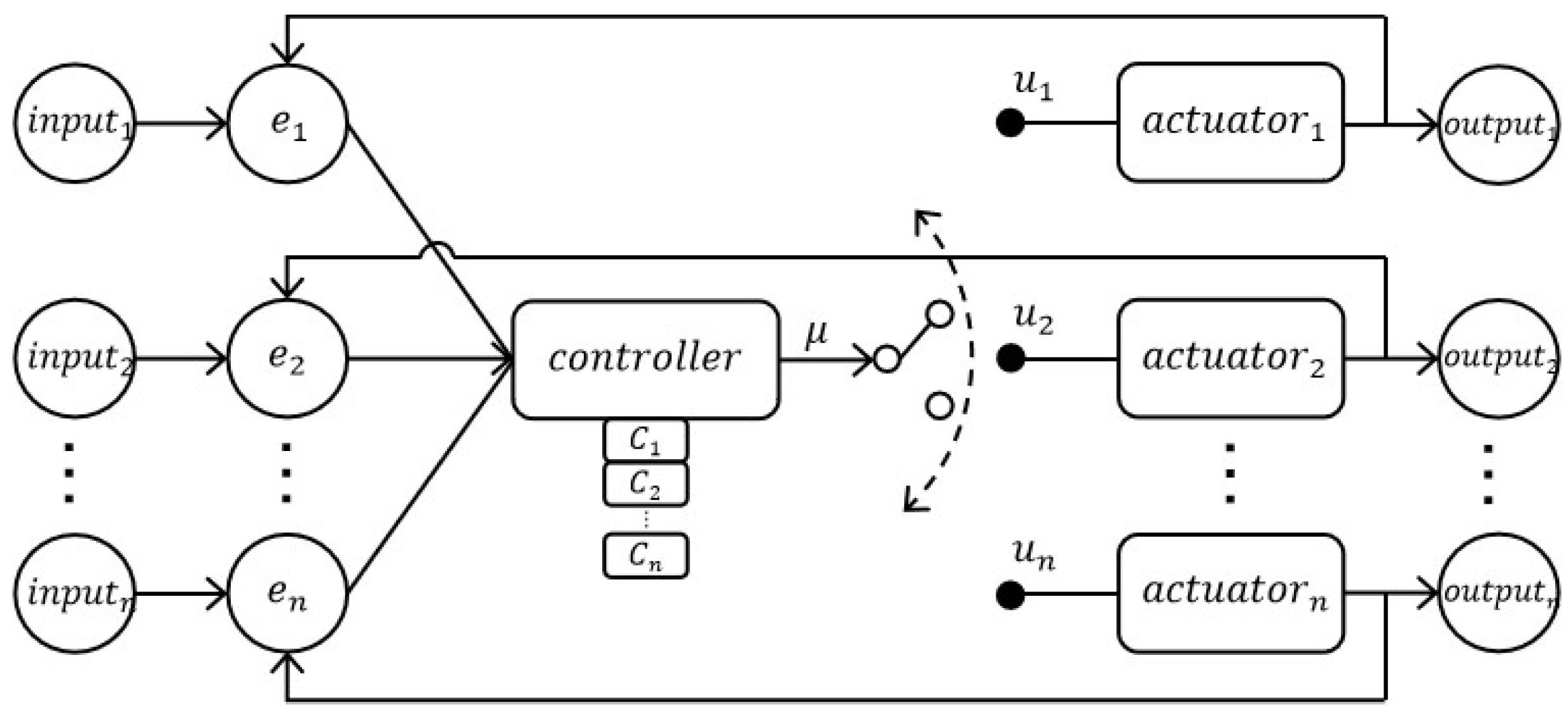
In a multi-thread control system, the numbers of controllers and plants usually do not match. More specifically, the number of controllers is generally smaller than that of plants. Figure 1 exemplifies a multi-thread control system with one controller and n actuators (n plants), and the same number of actuators and controlled plants are set. In this section, the form of the plants is described, and the problem is solved.
The following will analyze the multi-threaded control system proposed above.
Notation: This article uses standard notation, unless otherwise stated. R l denotes the l-dimensional Euclidean space. N and Z + denote a collection of positive integers. For the independent variables x and u, f ( x , u ) represents a function that varies with the independent variables. x denotes the Euclidean 2-norm. λ m ( A ) denotes the largest eigenvalue of matrix A. A T denotes the transpose of matrix A. In this article, t k denotes the triggered moment, not the sampling moment.

2.1. Plant Form

In this section, we consider a multi-thread control system with n nonlinear plants and m controllers ( m < n ) as follows:
x ˙ 1 = f 1 ( x 1 , u 1 ) x ˙ 2 = f 2 ( x 2 , u 2 ) x ˙ n = f n ( x n , u n )
where x i R l ( i { 1 , 2 , , n } , n N ) is the state vector of each of the n plants and u i ( x i ) ( i { 1 , 2 , , n } , n N ) is the actual control law of the ith actuator. Let μ j ( x i ) ( j { 1 , 2 , , m } , m N ) be the output signal of the jth controller and C i ( x i ) R n ( i { 1 , 2 , , n } , n N ) be the ideal control law of the ith plant, which can ensure the global stability of the ith plant during the continuous control process. When events are triggered, the output values μ j ( x i ) of the controllers are determined by the ideal control law C i ( x i ) . Because the number of controllers is smaller than that of plants, i.e., m < n , the controllers need to be switched to guarantee the stability of the plants. Now, we assume that t k is the kth ( k N ) switching time and x i , t k ( i { 1 , 2 , , n } , n N ) is the state vector of the ith plant at time t k . Therefore, the actual controller update law u i can be expressed as follows:
u i ( x i , t ) = μ j ( x i , t ) = C i ( x i , t ) , m u p d a t e d u i u i ( x i , t k ) , n m u n c h a n g e d u i
where i { 1 , 2 , , n } , ( n N ) , j { 1 , 2 , , m } , ( m N ) , and t [ t k , t k + 1 ) . It can be seen, according to (2), that the plants with updated controllers have time-varying and continuous control signals in t [ t k , t k + 1 ) , which ensures the stability of these plants until the next switching occurs. In fact, there are cases in which the controllers do not need to be continuously updated in t [ t k , t k + 1 ) after the switching occurs but simply at a certain time t k , which helps to save both controller and computation resources [1]. Therefore, another actual controller update law is given as follows:
u i ( x i , t ) = μ j ( x i , t k ) = C i ( x i , t k ) , m u p d a t e d u i u i ( x i , t k 1 ) , n m u n c h a n g e d u i
where i { 1 , 2 , , n } , ( n N ) , j { 1 , 2 , , m } , ( m N ) , and t [ t k , t k + 1 ) . In (3), the controllers only change at time t k and remain unchanged in [ t k , t k + 1 ) .
Let the pth ( 1 p 1 < p 2 < < p m n ) controller be updated at time t k and the qth ( 1 q 1 < q 2 < < q n m n ) controller be unchanged at time t k . Moreover, let e i , t R l , i { 1 , 2 , , n } , ( n N ) be the measurement errors of n plants, respectively. Measurement errors e i , t for t [ t k , t k + 1 ) are defined as e 1 , t = x 1 , t 1 , x 1 , t ,   e 2 , t = x 2 , t 2 , x 2 , t , , e n , t = x n , t 3 , x n , t , where { t i , } is the last triggered time of plant i.
Remark 1.
We assume a simple situation to illustrate the above definition of errors e 1 , t , e 2 , t , , e n , t . If the p 1 , p 2 , , p m th controllers are updated at t k , and the q 1 , q 2 , , q n m controllers are updated at t k 1 , then e p 1 , t = x p 1 , t k x p 1 , t , e p 2 , t = x p 2 , t k x p 2 , t , , e p m , t = x p m , t k x p m , t and e q 1 , t = x q 1 , t k 1 x q 1 , t , e q 2 , t = x q 2 , t k 1 x q 2 , t , , e q n m , t = x q n m , t k 1 x q n m , t .
Then, the following system form is given:
m u p d a t e d p l a n t s : x ˙ p 1 , t = f p 1 ( x p 1 , t , u p 1 ( x p 1 , t + e p 1 , t ) ) x ˙ p 2 , t = f p 2 ( x p 2 , t , u p 2 ( x p 2 , t + e p 2 , t ) ) x ˙ p m , t = f p m ( x p m , t , u p m ( x p m , t + e p m , t ) ) n m u p c h a n g e d p l a n t s : x ˙ q 1 , t = f q 1 ( x q 1 , t , u q 1 ( x q 1 , t + e q 1 , t ) x ˙ q 2 , t = f q 2 ( x q 2 , t , u q 2 ( x q 2 , t + e q 2 , t ) ) x ˙ q n m , t = f q n m ( x q n m , t , u q n m ( x q n m , t + e q n m , t ) )
To better illustrate the above system structure and the upcoming multi-thread control algorithm, we consider a linear time-invariant control puzzler with 4 plants and 2 controllers as follows:
x ˙ 1 = A 1 x 1 + b 1 u 1 y 1 = c 1 x 1 + d 1 u 1 , x ˙ 2 = A 2 x 2 + b 2 u 2 y 2 = c 2 x 2 + d 2 u 2 x ˙ 3 = A 3 x 3 + b 3 u 3 y 3 = c 3 x 3 + d 3 u 3 , x ˙ 4 = A 4 x 4 + b 4 u 4 y 4 = c 4 x 4 + d 4 u 4 .
The ideal controllers, C i , of the system are described as C 1 = k 1 x 1 ,   C 2 = k 2 x 2 ,   C 3 = k 3 x 3 , and C 4 = k 4 x 4 , where k 1 , k 2 , k 3 , and k 4 are the feedback gains of the controller. Controllers u 1 and u 3 are assumed to be updated at time t k . By (2), we have
u 1 ( x 1 , t ) = μ 1 ( x 1 , t ) = k 1 x 1 , t u 2 ( x 2 , t ) = u 2 ( x 2 , t k ) u 3 ( x 3 , t ) = μ 2 ( x 3 , t ) = k 3 x 3 , t u 4 ( x 4 , t ) = u 4 ( x 4 , t k )
where t [ t k , t k + 1 ) . Since two controllers are not continuously updated in t [ t k , t k + 1 ) , another actual controller update law is given as follows:
u 1 ( x 1 , t ) = μ 1 ( x 1 , t ) = k 1 x 1 , t u 2 ( x 2 , t ) = u 2 ( x 2 , t k 1 ) u 3 ( x 3 , t ) = μ 2 ( x 3 , t ) = k 3 x 3 , t u 4 ( x 4 , t ) = u 4 ( x 4 , t k 1 ) .
Considering the two conditions of the controllers, the state space expression of the tasks at time t ( t [ t k , t k + 1 ) ) can be replaced by
x ˙ 1 , t = A 1 x 1 , t + b 1 k 1 x 1 , t y 1 , t = c 1 x 1 , t + d 1 k 1 x 1 , t , x ˙ 2 , t = A 2 x 2 , t + b 2 u 2 ( x 2 , t k ) y 2 , t = c 2 x 2 , t + d 2 u 2 ( x 2 , t k ) x ˙ 3 , t = A 3 x 3 , t + b 3 k 3 x 3 , t y 3 , t = c 3 x 3 , t + d 3 k 3 x 3 , t , x ˙ 4 , t = A 4 x 4 , t + b 4 u 4 ( x 4 , t k ) y 4 , t = c 4 x 4 , t + d 4 u 4 ( x 4 , t k )
or
x ˙ 1 , t = A 1 x 1 , t + b 1 k 1 x 1 , t y 1 , t = c 1 x 1 , t + d 1 k 1 x 1 , t , x ˙ 2 , t = A 2 x 2 , t + b 2 u 2 ( x 2 , t k 1 ) y 2 , t = c 2 x 2 , t + d 2 u 2 ( x 2 , t k 1 ) x ˙ 3 , t = A 3 x 3 , t + b 3 k 3 x 3 , t y 3 , t = c 3 x 3 , t + d 3 k 3 x 3 , t , x ˙ 4 , t = A 4 x 4 , t + b 4 u 4 ( x 4 , t k 1 ) y 4 , t = c 4 x 4 , t + d 4 u 4 ( x 4 , t k 1 ) .
Remark 2.
The purpose of designing two update laws of controllers is to better approach the control methods of real-life devices. Although the control accuracy of the second control law scheme is not as good as the first one in the multi-thread control system, it can save resources better. This scheme is equivalent to adding a zero-order keeper behind each controller.

2.2. Problem Statement

As previously given, the structure of multi-thread control is designed for the multi-objective system with few controllers. Considering the influence of measurement errors on system stability, we will list the basic ISS condition definitions that can ensure the stability of the multi-tread control structure as follows:
Definition 1
([27]). The smooth function V N = [ V 1 , V 2 , , V n ] : R n R 0 + is defined as an ISS Lyapunov function for closed-loop system (1) or (4) if there exist class K functions α 1 , α 2 , β, and γ satisfying
α 1 ( x p 1 , t + + x p m , t + x q 1 , t + + x q n m , t ) V N α 2 ( x p 1 , t + + x p m , t + x q 1 , t + + x q n m , t )
V N x = i = 1 n m V q i x q i , t f q i ( x q i , t , u q i ( x q i , t + e q i , t ) ) + j = 1 m V p j x p j , t f p j ( x p j , t , u p j ( x p j , t + e p j , t ) ) β ( x p 1 , t + + x p m , t + x q 1 , t + + x q n m , t ) + γ ( e p 1 , t + + e p m , t + e q 1 , t + + e q n m , t ) .
where 1 p 1 < p 2 < < p m n and 1 q 1 < q 2 < < q n m n .
The status of a multi-thread system is sampled at time instants t 1 , t 2 , t 3 , , t n to determine the controller. These time instants are neither pre-determined nor pre-programmed but are instead implicitly specified by an event-triggered execution rule based on the condition of the plant. We assume that Δ 0 is the time it takes to calculate the control law and update the actuator from the state read by the sensor, so that t 1 + Δ , t 2 + Δ , t 3 + Δ , , t n + Δ are the time intervals for each controller to update completely. Moreover, at time t [ t k + Δ , t k + 1 + Δ ) , measurement errors e 1 , t , e 2 , t , , e n , t are the same as defined above. By (11), assuming that the limit of mistake to fulfill is
γ ( e p 1 , t + + e p m , t + e q 1 , t + + e q n m , t ) ξ β ( x p 1 , t + + x p m , t + x q 1 , t + + x q n m , t ) ( ξ > 0 )
the dynamics of V 1 , V 2 , , V n are bounded by
i = 1 n m V q i x q i , t f q i ( x q i , t , u q i ( x q i , t + e q i , t ) ) + j = 1 m V p j x p j , t f p j ( x p j , t , u p j ( x p j , t + e p j , t ) ) ( ξ 1 ) β ( x p 1 , t + x p 2 , t + + x p m , t + x q 1 , t + x q 2 , t + + x q n m , t ) .
Let ξ < 1 ; then, (13) can be replaced with
i = 1 n m V q i x q i , t f q i ( x q i , t , u q i ( x q i , t + e q i , t ) ) + j = 1 m V p j x p j , t f p j ( x p j , t , u p j ( x p j , t + e p j , t ) ) < 0
thus ensuring that V 1 + V 2 + + V n decreases. By carrying out the control tasks, inequality (12) can be enforced when
γ ( e p 1 , t + + e p m , t + e q 1 , t + + e q n m , t ) = ξ β ( x p 1 , t + + x p m , t + x q 1 , t + + x q n m , t ) ( ξ > 0 )
Then, the previous execution time, t k + 1 , is given as
t k + 1 = i n f { t > t k | γ ( e 1 , t + e 2 , t + + e n , t ) > ξ β ( x 1 , t + x 2 , t + + x n , t ) }
and we also have the multi-thread event-triggered condition as follows:
γ ( e 1 , t + e 2 , t + + e n , t ) > ξ β ( x 1 , t + x 2 , t + + x n , t )
Remark 3.
Equation (15) is the ISS-based event-triggered condition to guarantee that the Lyapunov function does not increase. Since the number of controllers, m, is less than the number of controlled plants, n, it is impossible for us to force errors e 1 , t , e 2 , t , , e n , t of all plants to 0 with the updated controller when the event-triggered condition is satisfied. The pth ( 1 p 1 < p 2 < < p m n ) controller whose e is updated to 0 at time t k is selected using certain rules.
Although stability is guaranteed by constructing simple execution rules, it is critical to ensure that the execution time is not arbitrarily close to the accumulation point to evaluate the feasibility of the scheduling policy. In other words, the proposed multi-thread event-triggered condition should promise that the Zeno phenomenon, which can lead to degraded system performance, controller failure, and even other problems, can be avoided.

3. Analysis of Stability

Based on multi-thread control structure (4) and event-triggered conditions (17), the main result is given as shown below.
Theorem 1.
Consider the multi-thread system described in (1) and (4); input u p 1 , u p 2 , , u p m ( 1 p 1 < p 2 < < p m n ) is updated with controller output μ i ( i = 1 , 2 , , m ) and ideal global control law C i ( i = 1 , 2 , , n ) described in (3). The closed-loop system is input-to-state stable with respect to the measurement errors, and all the signals are uniformly bounded with event-triggered conditions (17). Moreover, Zeno behavior can be avoided.
Proof of Theorem 1. 
Using (16), we define a compact set E for all e 1 , t , e 2 , t , , e n , t R l and all x 1 , t , x 2 , t , , x n , t R l that satisfies
e p 1 , t + + e p m , t + e q 1 , t + + e q n m , t γ 1 ( ξ β ( x p 1 , t + x p 2 , t + + x p m , t + x q 1 , t + x q 2 , t + + x q n m , t ) )
Since β 1 and γ are Lipschitz continuous, β 1 ( γ ( r p 1 , t + + r p m , t + r q 1 , t + + r q n m , t ) / ξ ) is continuous. For compact set E, let L be the Lipschitz constant [28], so that
| β 1 ( γ ( r p 1 , t + r p 2 , t + + r p m , t + r q 1 , t + r q 2 , t + + r q n m , t ) / ξ ) β 1 ( γ ( s p 1 , t + s p 2 , t + + s p m , t + s q 1 , t + s q 2 , t + + s q n m , t ) / ξ ) | L | ( r p 1 , t s p 1 , t ) + + ( r p m , t s p m , t ) + ( r q 1 , t s q 1 , t ) + + ( r q n m , t s q n m , t ) |
Let r p 1 , t = e p 1 , t , r p 2 , t = e p 2 , t , , r p m , t = e p m , t , r q 1 , t = e q 1 , t , r q 2 , t = e q 2 , t , , r q n m , t = e q n m , t , s p 1 , t = = s p m , t = s q 1 , t = = s q n m , t = 0 , so that (19) can be replaced with
β 1 ( γ ( e p 1 , t + + e p m , t + e q 1 , t + + e q n m , t ) / ξ ) L ( e p 1 , t + + e p m , t + e q 1 , t + + e q n m , t )
Note that by enforcing the more conservative inequality L ( e p 1 , t + + e q n m , t ) x p 1 , t + + x q n m , t , we guarantee β 1 ( γ ( e p 1 , t + + e p m , t + e q 1 , t + e q n m , t ) / ξ ) x p 1 , t + + x q n m , t . The above proves that the time interval between successive triggered condition actions is bounded.
Considering the closed-loop form in (4), f i ( x i , t , u i ( x i , t + e i , t ) ) ( i Z + , i m a x = n ) are Lipschitz continuous on compacts, that is,
| F ( Π , u ( Π , Ψ ) ) F ( Π , u ( Π , Ψ ) ) | L | ( Π , Ψ ) ( Π , Ψ ) |
where
F ( Π , u ( Π , Ψ ) ) = ( f p 1 ( r p 1 , t , u p 1 ( r p 1 , t + s p 1 , t ) ) + f p 2 ( r p 2 , t , u p 2 ( r p 2 , t + s p 2 , t ) ) + + f p m ( r p m , t , u p m ( r p m , t + s p m , t ) ) + f q 1 ( r q 1 , t , u q 1 ( r q 1 , t + s q 1 , t ) ) + f q 2 ( r q 2 , t , u q 2 ( r q 2 , t + s q 2 , t ) ) + + f q n m ( r q n m , t , u q n m ( r q n m , t + s q n m , t ) ) )
and
( Π , Ψ ) = ( ( r p 1 , t , s p 1 , t ) + ( r p 2 , t , s p 2 , t ) + + ( r p m , t , s p m , t ) + ( r q 1 , t , s q 1 , t ) + ( r q 2 , t , s q 2 , t ) + + ( r q n m , t , s q n m , t ) )
Similarly, F ( Π , u ( Π , Ψ ) ) , ( Π , Ψ ) is obtained. If the set
r p 1 , t = x p 1 , t , , r p m , t = x p m , t r q 1 , t = x q 1 , t , , r q n m , t = x q n m , t s p 1 , t = e p 1 , t , , s p m , t = e p m , t s q 1 , t = e q 1 , t , , s q n m , t = e q n m , t
and otherwise are 0. Then, the formula can obtained:
| f p 1 ( r p 1 , t , u p 1 ( r p 1 , t + s p 1 , t ) ) + + f p m ( r p m , t , u p m ( r p m , t + s p m , t ) ) + f q 1 ( r q 1 , t , u q 1 ( r q 1 , t + s q 1 , t ) ) + + f q n m ( u q n m ( r q n m , t + s q n m , t ) ) | L ( x p 1 , t + x p 2 , t + + x p m , t + x q 1 , t + x q 2 , t + + x q n m , t + e p 1 , t + e p 2 , t + + e p m , t + e q 1 , t + e q 2 , t + + e q n m , t )
Now, we define X N = x q 1 , t + + x q n m , t + x p 1 , t + + x p m , t and E N = e q 1 , t + + e q n m , t + e p 1 , t + + e p m , t ; the inter-event times can be decided according to the dynamics of E N X N .
E N X N = d [ ( e q 1 T e q 1 ) 1 2 + ( e q 2 T e q 2 ) 1 2 + + ( e p m T e p m ) 1 2 ] d t [ ( x q 1 T x q 1 ) 1 2 + ( x q 2 T x q 2 ) 1 2 + + ( x p m T x p m ) 1 2 ] = 1 e q 1 e q 1 T x ˙ q 1 1 e q 2 e q 2 T x ˙ q 2 1 e p m e p m T x ˙ p m X N E N ( 1 x q 1 x q 1 T x ˙ q 1 + + 1 x p m x p m T x ˙ p m ) X N 2 1 e q 1 e q 1 x ˙ q 1 + + 1 e q n m e q n m x ˙ q n m X N + 1 e p 1 e p 1 x ˙ p 1 + + 1 e p m e p m x ˙ p m X N
+ E N ( 1 x q 1 x q 1 x ˙ q 1 + + 1 x q n m x q n m x ˙ q n m ) X N 2 + E N ( 1 x p 1 x p 1 x ˙ p 1 + + 1 x p m x p m x ˙ p m ) X N 2 ( 1 + E N X N ) L ( X N + E N ) X N = L ( 1 + E N X N ) ( 1 + E N X N )
We define g = E N X N , so that g ˙ L ( 1 + g ) 2 and g ( t ) Φ ( t , Φ 0 ) , where Φ ( t , Φ 0 ) is the solution of Φ ˙ = L ( 1 + Φ ) 2 satisfying Φ ( 0 , Φ 0 ) = Φ 0 . The time of delay for the multi-thread control system is denoted by Δ 0 .
We assume that Δ = 0 , where the execution time is limited by Φ equaling 0 to 1 M and the interval time is limited by solution τ R + of Φ ( 0 , Φ 0 ) = 1 M . It is obtained, using integration, that Φ ( 0 , Φ 0 ) = τ L 1 τ L , so τ = 1 L + L M .
Now, we discuss the circumstances when Δ > 0 . First, we choose the ξ satisfying ξ < ξ < 1 . M is the Lipschitz constant of β 1 ( γ ( e p 1 , t + + e p m , t + e q 1 , t + + e q n m , t ) / ξ ) . We assume that ς 1 R + satisfies Φ ( ς 1 , 1 M ) = 1 M , where ς 1 always exists when Φ > 0 is continuous and 1 M < 1 M . We guarantee that for t [ t k , t k + ς 1 ) , we have e p 1 , t + + e p m , t + e q 1 , t + + e q n m , t x p 1 , t + + x p m , t + x q 1 , t + + x q n m , t M and thus also γ ( e p 1 , t + + e p m , t + e q 1 , t + + e q n m , t ) ξ β ( x p 1 , t + + x p m , t + x q 1 , t + + x q n m , t ) . Since ξ < 1 , asymptotic stability still ensures that the execution time is bounded by τ + Δ , where τ is defined as the time that Φ evolves from
e p 1 , t k + Δ + + e q 1 , t k + Δ + + e q n m , t k + Δ x p 1 , t k + Δ + + x q 1 , t k + Δ + + x q n m , t k + Δ = x p 1 , t k x p 1 , t k + Δ + + x q n m , t k x q n m , t k + Δ x p 1 , t k + Δ + + x q 1 , t k + Δ + + x q n m , t k + Δ
to 1 M . Since Φ > 0 , a small enough Δ value to satisfy the mechanism is picked. It now follows, from the continuity of x p 1 , t k x p 1 , t k + Δ + + x q n m , t k x q n m , t k + Δ x p 1 , t k + Δ + + x q 1 , t k + Δ + + x q n m , t k + Δ with respect to Δ , the existence of ς 2 > 0 , such that for any 0 Δ ς 2 , we have
e p 1 , t k + Δ + + e q 1 , t k + Δ + + e q n m , t k + Δ x p 1 , t k + Δ + + x q 1 , t k + Δ + + x q n m , t k + Δ < 1 M .
Finally, we choose ς = m i n [ ς 1 , ς 2 ] .
It can be obtained according to the above proof that there exists ς > 0 in such a way that for all response times Δ [ 0 , ς ] , there exists a time τ R + such that inter-execution times { t k + 1 t k } k N τ implicitly defined by execution rule (15) with ξ < 1 . So, Zeno behavior can be avoided for the system. □
Remark 4.
In a multi-thread control structure, the controller is quickly updated under the action of the triggered condition, and even in a limited time, it requires an infinite number of updates. This situation is called Zeno phenomenon. This leads to problems such as system performance degradation and controller failure. In the event-triggered structure with the “one-to-one” feature, infinite switching can be regarded as a continuous update process of the controllers. However, in the control structure with the characteristics of “one-to-many” or “minority-to-majority”, it is impossible for resources to serve multiple controlled plants at the same time. So, the Zeno phenomenon in multi-thread control leads to greater risk of instability. The above proof process shows that the proposed algorithm can avoid the Zeno phenomenon.
We assume that there are n tasks in the system, T 1 , T 2 , T 3 , , T n , controlled by m controllers. These controlled tasks are ranked in a priority order that determines when they are implemented. Since γ ( e p 1 , t + e p 2 , t + + e p m , t + e q 1 , t + e q 2 , t + + e q n m , t ) = ξ β ( x p 1 , t + x p 2 , t + + x p m , t + x q 1 , t + x q 2 , t + + x q n m , t ) is the execution rule, we judge the norm of e i , t , i Z + , ( i m a x = n ) . If e 1 , t > e 2 , t > e 3 , t > > e n , t , then T 1 > T 2 > T 3 > > T n . The m controllers are assigned to tasks T 1 , T 2 , , T m .
With the event-triggered mechanism, the proposed multi-thread control algorithm can thoroughly address the mismatch problem between m controllers and n actuators online, which makes the algorithm well suited to the needs of real-world engineering applications.

4. Simulation and Experiments

Now, the three plants of the system are considered in Section 2. For the convenience of simulation with the proposed algorithm, we selected the linear control system in (5) (see [29]),
p l a n t 1 : x ˙ 11 x ˙ 12 = 0 1 2 3 x 11 x 12 + 0 1 u 1 p l a n t 2 : x ˙ 21 x ˙ 22 = 0 1 2 2 x 21 x 22 + 0 1 u 2 p l a n t 3 : x ˙ 31 x ˙ 32 = 0 2 2 3 x 31 x 32 + 0 1 u 3
stabilized by the linear feedback u 1 = x 11 4 x 12 , u 2 = x 21 4 x 22 , and u 3 = x 31 4 x 32 . Therefore, we obtain
K 1 = K 2 = K 3 = 1 4 .

4.1. Traditional Event-Triggered Mechanism

Firstly, the traditional event-triggered rules were applied to the above-mentioned system with a mismatch between the number of controllers and the number of controlled plants. The traditional event-triggered mechanism is a fixed threshold strategy. The threshold under this triggered mechanism is fixed and does not change with the control signal, and the threshold is closely related to the errors of the system.
The traditional event-triggered mechanism is given as follows:
t k + 1 = i n f { t > t k | γ ( e 1 , t + e 2 , t + + e n , t ) > L }
where L is a fixed threshold related to the errors. At the triggered moment, only the non-triggered controlled plants have error values, and the triggered-controlled plants have errors of 0. When the next trigger time approaches, L approaches the error values of the system; then, the calculation formula of L is as follows:
lim t t k + 1 e 1 , t + e 2 , t + + e n , t = L
Figure 2 shows how and at what time the plants were triggered based on the traditional control algorithm. It can be seen from the simulation diagram that the traditional event-triggered mechanism could make three events be alternately controlled. However, if the triggered condition is designed for the purpose of saving resources in a multi-thread control system, the traditional form is not suitable. According to the simulation results, it can be seen that this traditional event-triggered scheme with a fixed threshold did not achieve the desired effect.

4.2. Proposed Event-Triggered Mechanism

These three plants are in one system, using a decision-making process prompted by an event to decide which task to perform at time k. Using V = x T Υ x as a Lyapunov function, we obtain ( A + B K ) T Υ + Υ ( A + B K ) = Ω , where Υ 1 , Υ 2 , and Υ 3 , and Ω 1 , Ω 2 , and e Ω 3 are defined as
Υ 1 = Υ 2 = Υ 3 = 1 1 4 1 4 1 Ω 1 = 1 2 1 4 1 4 3 2 , Ω 2 = 1 2 1 2 3 2 5 2 , Ω 3 = 1 2 3 4 3 4 3 2 .
Using (25), the smallest eigenvalues of Ω 1 ,   Ω 2 , and Ω 3 are λ m ( Ω 1 ) > 0.44 ,   λ m ( Ω 2 ) > 0.17 , and λ m ( Ω 3 ) > 0.57 , and we obtain | K 1 T B 1 T Υ 1 + Υ 1 B 1 K 1 | , | K 2 T B 2 T Υ 2 + Υ 2 B 2 K 2 | , and | K 3 T B 3 T Υ 3 + Υ 3 B 3 K 3 | . We choose ξ = 0.04 since 4 ξ must be less than 0.17 , and obtain the execution rule e 1 , t + e 2 , t + e 3 , t ξ ( x 1 , t + x 2 , t + x 3 , t ) , in the same way as in [1].
In Figure 3, we can see a lot of intersections in the states of the plants, but the general trends are consistent. The relationship between inputs u 1 , u 2 , and u 3 and states x 1 , x 2 , and x 3 of the three plants is given in (25). In fact, since B ,   Υ , and K are the same in the three plants, the assumed relationship is the same, only with respect to the state of each plant. In Figure 4, inputs u 1 , u 2 , and u 3 of the system are displayed.
Figure 5 shows how and at what time the plants were triggered based on the proposed multi-thread real-time control algorithm. During the period from 0 to 10, system 1 was triggered 260 times; system 2, 115 times; and system 3, 305 times. No controller update was triggered for the remaining 9319 times. The suggested algorithm implements the underlying notion of devoting extra Central Processing Unit (CPU) time to control activities in order to increase control performance. In Figure 6, we see that the error norm of the system never reached ξ ( x p 1 , t + x p 2 , t + + x p m , t + x q 1 , t + x q 2 , t + + x q n m , t ) , and the goal was achieved.
Comparing Figure 2 and Figure 5, it can be seen that firstly, the modeling scheme of the multi-thread control system is feasible and the description of the update of the controller is reasonable. Secondly, the proposed event-triggered mechanism can be applied to multi-thread control systems and achieve the effect of saving resources.
The simulations show that the controller switching logic of the proposed multi-thread control system is feasible. Existing triggered mechanisms include event-triggered mechanisms, self-triggered mechanisms, time-triggered mechanisms, etc., mainly for the “one-to-one” control system structure. When the triggered condition is met, the system controller is immediately updated. However, a multi-thread control structure, when multiple triggered conditions are met at the same time, faces the problem of how to allocate controller resources first, and it is impossible to simply perform the “trigger and update” operation. The proposed algorithm solves how to design a flexible event-triggered mechanism to allocate system resources according to the different requirements of each subsystem to dynamic performance and static performance, so as to ensure the feasibility and stability of the multi-thread control algorithm.

5. Conclusions

This paper presents a novel multi-thread real-time control algorithm based on an event-triggered mechanism to address the mismatch problem in hybrid systems. Both linear and nonlinear system forms are considered to describe the mismatch problem, i.e., the number of controllers is different from that of plants, for multi-thread controllers. To solve the switching problem, an event-triggered mechanism is proposed, and ISS-based triggered conditions in the multi-thread control algorithm are studied. Finally, a minimal time interval is proved to exist between the consecutive execution of one control task and that of another, which avoids the Zeno phenomenon for the whole system. The simulation results exhibit that the proposed algorithm is effective and can achieve the resource saving goal for control systems. For the application of the above control methods in multi-thread control systems, our future research trends and development directions mainly include the following aspects: (a) The case where different controllers have different event-triggered mechanisms can be investigated. This event-triggered control system can improve the fault tolerance and reliability of the system and reduce communication overhead and calculation load. (b) Design and optimization of event-triggered interval. The interval between event triggers directly affects the performance and stability of the system. How to design and optimize the event-triggered interval to achieve the optimal performance and maximum stability of the system is still one of the main research objectives of this field.

Author Contributions

Conceptualization, Y.W. and H.G.; methodology, Y.W.; software, Y.Y.; formal analysis, P.X.; writing, Y.W. All authors have read and agreed to the published version of the manuscript.

Funding

The authors disclose receipt of the following financial support for the research, authorship, and/or publication of this article: This work was supported in part by Natural Science Foundation of Shaanxi under grant 2022JQ-651.

Data Availability Statement

We did not create new data sets in this article.

Conflicts of Interest

The authors declare no conflict of interest.

References

  1. Tabuada, P. Event-triggered real-time scheduling of stabilizing control tasks. IEEE Trans. Autom. Control 2007, 52, 1680–1685. [Google Scholar] [CrossRef]
  2. Charron, S.; Koechlin, E. Divided representation of concurrent goals in the human frontal lobes. Science 2010, 328, 360–363. [Google Scholar] [CrossRef]
  3. Fan, J.; Flombaum, J.I.; McCandliss, B.D.; Thomas, K.M.; Posner, M.I. Cognitive and brain consequences of conflict. Neuroimage 2003, 18, 42–57. [Google Scholar] [CrossRef] [PubMed]
  4. Donkers, M.C.F.; Heemels, W.P.M.H. Output-based event-triggered control with guaranteed L-gain and improved event-triggering. In Proceedings of the 49th IEEE Conference on Decision and Control (CDC), Atlanta, GA, USA, 15–17 December 2010; pp. 3246–3251. [Google Scholar]
  5. Heemels, W.H.; Donkers, M.C.F.; Teel, A.R. Periodic event-triggered control for linear systems. IEEE Trans. Autom. Control 2012, 58, 847–861. [Google Scholar] [CrossRef]
  6. Heemels, W.P.; Johansson, K.H.; Tabuada, P. An introduction to event-triggered and self-triggered control. In Proceedings of the 2012 IEEE 51st IEEE conference on decision and control (CDC), Maui, HI, USA, 10–13 December 2012; pp. 3270–3285. [Google Scholar]
  7. Marti, P.; Fuertes, J.M.; Fohler, G.; Ramamritham, K. Improving quality-of-control using flexible timing constraints: Metric and scheduling. In Proceedings of the 23rd IEEE Real-Time Systems Symposium, Austin, TX, USA, 3–5 December 2002; pp. 91–100. [Google Scholar]
  8. Mazo, M., Jr.; Anta, A.; Tabuada, P. An ISS self-triggered implementation of linear controllers. Automatica 2010, 46, 1310–1314. [Google Scholar] [CrossRef]
  9. Postoyan, R.; Tabuada, P.; Nešić, D.; Anta, A. A framework for the event-triggered stabilization of nonlinear systems. IEEE Trans. Autom. Control 2014, 60, 982–996. [Google Scholar] [CrossRef]
  10. Åarzén, K.E. A simple event-based PID controller. IFAC Proc. Vol. 1999, 32, 8687–8692. [Google Scholar] [CrossRef]
  11. Hristu-Varsakelis, D.; Kumar, P.R. Interrupt-based feedback control over a shared communication medium. In Proceedings of the 41st IEEE Conference on Decision and Control, Las Vegas, NV, USA, 10–13 December 2002; Volume 3, pp. 3223–3228. [Google Scholar]
  12. Astrom, K.J.; Bernhardsson, B.M. Comparison of Riemann and Lebesgue sampling for first order stochastic systems. In Proceedings of the 41st IEEE Conference on Decision and Control, Las Vegas, NV, USA, 10–13 December 2002; Volume 2, pp. 2011–2016. [Google Scholar]
  13. Voulgaris, P. Control of asynchronous sampled data systems. IEEE Trans. Autom. Control 1994, 39, 1451–1455. [Google Scholar] [CrossRef]
  14. Tabuada, P.; Wang, X. Preliminary results on state-trigered scheduling of stabilizing control tasks. In Proceedings of the 45th IEEE Conference on Decision and Control, San Diego, CA, USA, 13–15 December 2006; pp. 282–287. [Google Scholar]
  15. Mazo, M.; Tabuada, P. Decentralized event-triggered control over wireless sensor/actuator networks. IEEE Trans. Autom. Control 2011, 56, 2456–2461. [Google Scholar] [CrossRef]
  16. Stöcker, C.; Lunze, J. Event-based control of nonlinear systems: An input-output linearization approach. In Proceedings of the 2011 50th IEEE Conference on Decision and Control and European Control Conference, Orlando, FL, USA, 12–15 December 2011; pp. 2541–2546. [Google Scholar]
  17. Postoyan, R.; Anta, A.; Heemels, W.P.M.H.; Tabuada, P.; Nešić, D. Periodic event-triggered control for nonlinear systems. In Proceedings of the 52nd IEEE Conference on Decision and Contro, Firenze, Italy, 10–13 December 2013; pp. 7397–7402. [Google Scholar]
  18. Alur, R.; Courcoubetis, C.; Halbwachs, N.; Henzinger, T.A.; Ho, P.H.; Nicollin, X.; Yovine, S. The algorithmic analysis of hybrid systems. Theor. Comput. Sci. 1995, 138, 3–34. [Google Scholar] [CrossRef]
  19. Chen, Z.; Xia, B.; You, C.; Mi, C.C. A novel energy management method for series plug-in hybrid electric vehicles. Appl. Energy 2015, 145, 172–179. [Google Scholar] [CrossRef]
  20. Zhang, L. VirtualClock: A new traffic control algorithm for packet-switched networks. ACM Trans. Comput. Syst. TOCS 1991, 9, 101–124. [Google Scholar] [CrossRef]
  21. Zheng, Y.F.; Fan, Y. Robot force sensor interacting with environments. IEEE Trans. Robot. Autom. 1991, 7, 156–164. [Google Scholar] [CrossRef]
  22. Cervin, A.; Eker, J.; Bernhardsson, B.; Årzén, K.E. Feedback–feedforward scheduling of control tasks. Real-Time Syst. 2002, 23, 25–53. [Google Scholar] [CrossRef]
  23. Lemmon, M.; Chantem, T.; Hu, X.S.; Zyskowski, M. On self-triggered full-information h-infinity controllers. In International Workshop on Hybrid Systems: Computation and Control: 10th International Workshop, Pisa, Italy, April 2007; Springer: Berlin/Heidelberg, Germany, 2007; pp. 371–384. [Google Scholar]
  24. Li, T.F.; Fu, J. Event-triggered control of switched linear systems. J. Frankl. Inst. 2017, 354, 6451–6462. [Google Scholar] [CrossRef]
  25. Li, T.F.; Fu, J.; Deng, F.; Chai, T. Stabilization of switched linear neutral systems: An event-triggered sampling control scheme. IEEE Trans. Autom. Control 2018, 63, 3537–3544. [Google Scholar] [CrossRef]
  26. Mahmoud, M.S.; Memon, A.M. Aperiodic triggering mechanisms for networked control systems. Inf. Sci. 2015, 296, 282–306. [Google Scholar] [CrossRef]
  27. Liu, A.; Zhang, W.A.; Chen, M.Z.; Yu, L. Moving horizon estimation for mobile robots with multirate sampling. IEEE Trans. Ind. Electron. 2016, 64, 1457–1467. [Google Scholar] [CrossRef]
  28. Heinonen, J. Lectures on Analysis on Metric Spaces; Springer Science & Business Media: San Francisco, CA, USA, 2001; pp. 20–40. [Google Scholar]
  29. Gao, H.; Wang, Y. A multi-thread control algorithm with update delays based on event-triggered mechanism. Meas. Control 2022, 2022, 00202940221139568. [Google Scholar] [CrossRef]
Figure 1. A multi-thread control system.
Electronics 12 02129 g001
Figure 2. The plants triggered in the system at time k based on the traditional event-triggered mechanism.
Electronics 12 02129 g002
Figure 3. States x 1 , x 2 , and x 3 of plants in the system.
Electronics 12 02129 g003
Figure 4. Inputs u 1 , u 2 , and u 3 of plants in the system.
Electronics 12 02129 g004
Figure 5. The plants triggered in the system at time k.
Electronics 12 02129 g005
Figure 6. Evolution of e 1 + e 2 + e 3 , ξ ( x 1 + x 2 + x 3 ) , and ξ ( x 1 + x 2 + x 3 ) for Δ = 0.001 .
Electronics 12 02129 g006
Disclaimer/Publisher’s Note: The statements, opinions and data contained in all publications are solely those of the individual author(s) and contributor(s) and not of MDPI and/or the editor(s). MDPI and/or the editor(s) disclaim responsibility for any injury to people or property resulting from any ideas, methods, instructions or products referred to in the content.

