Abstract
With the continuous enhancement of weak grid characteristics, the negative effects of grid voltage feedforward (GVF) and PLL on grid-connected inverters become more and more serious and are coupled. Therefore, it is difficult to effectively solve the system stability problem by only improving the PLL structure. Firstly, based on an improved phase-locked loop structure (CCF-PLL) with complex coefficient filter and considering the influence of GVF, the output admittance model of a grid-connected inverter is established. Through stability analysis, it is found that conventional GVF leads the total output admittance phase of the inverter, thus reducing the system stability margin under the weak grid. Then, an improved admittance remodeling strategy of the grid-connected inverter is proposed. An all-pass filter is introduced into the GVF loop to correct the phase of the total output admittance of the inverter, and the phase margin is used as the constraint to design the control parameters, which effectively improves the stability of the system under the weak grid. Finally, the simulation results show that, compared with traditional GVF, the proposed strategy can obviously improve the distortion of grid-connected current waveforms and improve system stability.
1. Introduction
In remote areas, new energy generation needs to be transported to the load center via long-distance lines, and the power grid exhibits weak grid characteristics with a low short circuit ratio (SCR) [1,2,3]. In weak grids (2 < SCR < 3), the grid impedance cannot be ignored [4,5], and both traditional synchronous reference frame phase-locked loop (SRF-PLL) and grid voltage feedforward (GVF) introduce negative admittance [6]; resulting in an advanced output admittance phase of the inverter [7,8]; making the system difficult to operate stably due to a decreased stability margin. Therefore, improving the stability of grid-connected inverters under weak grid conditions is particularly important [9].
Regarding grid-connected inverters that only consider the impact of SRF-PLL, the stability of the system under weak grid conditions can be improved by reshaping the inverter admittance through improving the PLL structure [10,11]. The literature [12,13] proposed methods of introducing a second-order low-pass filter to improve the PLL structure and constructing a new type of PLL structure, respectively, to reshape the impedance characteristics of the PLL branch, thereby improving system dynamic performance and phase margin. However, the above strategies can cause the phase of the grid voltage collected by the PLL to lag at the fundamental frequency, causing the grid voltage to be out of sync with the grid current. Therefore, the literature [14,15] proposed a PLL structure with a complex coefficient filter (CCF-PLL), which can improve system dynamic performance and phase margin while ensuring that the phase collected by the PLL does not lag at the fundamental frequency.
GVF control can suppress the background harmonics of the grid voltage and improve the quality of the grid current, and, thus, it has been widely used in grid-connected inverters [16,17,18]. However, grid voltage feedforward can reduce the adaptability of grid-connected inverter systems to a weak grid [19,20]. The literature [21,22,23] has pointed out that the feedforward branch can reduce the stability margin of the grid-connected inverter under weak grid conditions, and may lead to harmonic instability in the grid-connected current. The literature [24,25] has also indicated that the introduction of traditional grid voltage feedforward can cause a significant amplification of background harmonics near the cutoff frequency of the system loop gain, resulting in a significant decrease in the robustness of the inverter under weak grid conditions. The literature [26,27] proposes a phase advance compensation method to increase the phase angle of inverter output impedance, reduce the instability region generated by GVF, and improve the robustness of the system to the impedance changes of the power grid. The literature [28] proposed an improved control strategy based on the combination of phase compensation and multiple resonant controllers. Multiple resonant links were added to GVF branches, and a phase compensator with adaptive parameter adjustment was introduced into the forward path to improve the phase margin and the adaptability of the system.
As can be seen from the above, there are many effective solutions considering only the influence of SRF-PLL on a grid-connected inverter system, among which the method proposed in the literature [14] is, relatively, better. However, with the continuous enhancement of weak grid characteristics, the interaction frequency band between grid impedance and system expands, and the negative effects of GVF and phase-locked loop on grid-connected inverters are intensified and interactive coupling occurs [29,30]. The inverters need to be able to operate stably under the condition of wide-range transformation of grid impedance [31]. In this case, the influence of GVF on inverters cannot be ignored.
Therefore, the control model of a grid-connected inverter using CCF-PLL is established, and the influence of GVF is considered on this basis. The analysis shows that GVF reduces the phase margin of the grid-connected inverter system using CCF-PLL in a weak grid, thus restricting the stable operation of the system. An admittance remodeling strategy based on improved GVF is proposed. An all-pass filter is introduced into the GVF loop to reduce the output admittance phase, improve the phase margin of inverters in a weak grid, and enhance the adaptability of the system to a weak grid.
2. Admittance Model and Stability Analysis of Grid-Connected Inverter
2.1. Output Admittance Model of Inverter System
Figure 1 shows the control structure of a single-phase LCL grid-connected inverter. The LCL filter consists of inductor L1, capacitor Cf and inductor L2. i1 is the current of L1, ic is the current of Cf, ig is the grid-connected current, kc is the ic feedback coefficient, H1 is the ig feedback coefficient, Gc(s) is the proportional resonance controller, Udc is the ideal DC voltage output of the pre-stage photovoltaic power generation unit, upcc is the common-point voltage, ir is the ig reference value. The phase is synchronized with the upcc phase by CCF-PLL, and the amplitude is always the given value Ir. Gc(s) is the current controller. Zg is the impedance of the power grid. For the analysis of extreme cases, Zg is assumed to be pure inductive, denoting Zg = sLg.
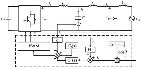
Figure 1.
Structure diagram of simple-phase LCL grid connected inverter.
According to Figure 1, the control block diagram of an LCL single-phase grid-connected inverter in a weak grid is established, as shown in Figure 2a.
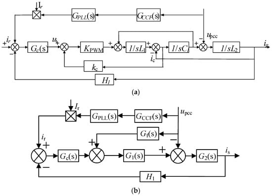
Figure 2.
Equivalent control block diagram of simple-phase LCL grid-connected inverter. (a) Without GVF; (b) With GVF.
Figure 2b is the equivalent control block diagram of Figure 2a. In Figure 2b, Gf(s) is the traditional grid voltage proportional feedforward, and the expression is 1/kpwm. GPLL(s) is the transfer function of SRF-PLL [8]. GCCF(s) is the transfer function of CCF [24]. Gc(s) is the current controller. G1(s) and G2(s) are the transfer functions after equivalent transformation in the current loop [32], and their expressions are as follows:
where, kpwm represents the gain of the inverter. While a bipolar sinusoidal pulse width modulation is used for the inverter, the transfer magnitude of the inverter bridge kpwm can be approximated by Udc/2 [33]. kpp is the proportional coefficient and kpi is the integral coefficient. kCCF is an adaptive adjustment coefficient, and, in order to avoid the interaction between CCF and SRF-PLL [14], kCCF is set to 0.2.
The relationship between ir(s) and uPCC(s) is as follows:
Substituting Formula (3) into Formula (2), the grid-connected current can be rewritten as follows:
According to Formula (5), the equivalent output acceptance model of the inverter side can be established, taking into account CCF-PLL and GVF [34]. At the same time, the Thevenin equivalent model is performed for the power grid side. By connecting the power grid side and the inverter side through PCC, the interactive equivalent circuit of the inverter and the weak power grid can be obtained [35], as shown in Figure 3.
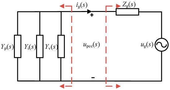
Figure 3.
Equivalent circuit for grid-connected system.
In Figure 3, Yp(s) represents CCF-PLL admittance, Yi(s) represents inverter output admittance, and Yv(s) represents GVF admittance, whose expressions are as follows:
where, kp represents the proportional coefficient, kr represents the harmonic coefficient, ωi represents the bandwidth coefficient, ω0 represents fundamental frequency angular frequency.
The expression of the total output admittance Yo(s) of the inverter system is:
The total output admittance without GVF is denoted as Yo1(s), whose expression is Yo1(s) = Yp(s) + Yi(s).
2.2. Stability Analysis
According to Figure 3 and Formula (9), the expression of ig(s) can be rewritten as:
where, Yg(s) is grid admittance, and the expression is 1/Zg(s).
According to the stability criterion based on impedance [36], system stability can be ensured by reasonably designing control parameters so that Yo(s) does not contain unstable poles under the strong grid. The stability of the system under a weak grid is determined by Yo(s)/Yg(s), and the stability condition is as follows: As , the phase difference between Yo(s) and Yg(s) is less than 180°; that is, the admittance ratio of Yo(s)/Yg(s) phase margin (PM) is greater than 0°. Since the phase of Yg(s) is −90° in all frequency bands, the stability condition can be rewritten as: when, and only when , the phase of Yo(s) is less than 90°.
Figure 4 shows the Bode diagram of Yo1(s) and Yo(s) when SCR = 2. In this figure, the phase of output admittance of Yo1(s) in the frequency band of fmin(133 Hz)~fmax(2375 Hz) is from 19°~53°, the amplitude is about −25 dB, and the PM is 54.2°, indicating that the system is stable. After GVF is added, the phase of the total output admittance Yo(s) is advanced in the fmin~fmax frequency band, and the f1(178 Hz)~f2(644 Hz) frequency band is greater than 90°, resulting in a PM of −8.8° (fc = 439 Hz), and the system is unstable. It can be seen that the addition of GVF will affect the phase of the total output admittance of the system, and the influence frequency range is fmin~fmax, making the phase margin of the CCF-PLL inverter system in a weak grid negative, which seriously affects the stability of the system. Therefore, it is necessary to eliminate the negative effects of GVF.
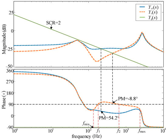
Figure 4.
Bode diagram for Yo1(s) and Yo(s).
3. Inverter Admittance Remodeling Strategy Based on Improved GVF
3.1. The Influence of Traditional GVF on System Stability
According to the above analysis, when considering GVF, a CCF-PLL grid-connected inverter system has poor stability under weak grids, so it is necessary to analyze the influence of GVF on system stability on this basis. Figure 5 shows the logarithmic frequency characteristics of Yv(s). It can be seen that its amplitude is about −25 dB in the fmin~fmax frequency band, and its phase is from 48.9°~227° (the phase at fmin is 227°). The high phase of Yv(s)) should be the reason for Yo(s) phase advance.
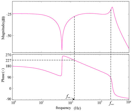
Figure 5.
Bode diagram of Yv(s).
In order to further clarify the effect of GVF on Yo(s) phase, a phasor diagram in circuit theory is applied to analyze it. By the foregoing, the inside fmin~fmax spectrum, Yo1(s) the amplitude of which basically remains the same, and Yv(s) have the same amplitude, so for convenience of analysis, it can be assumed Yv(s) and Yo1(s) values are equal; remember Yv(s) phase is φv, Yo1(s) phase is φo1, Yo(s) phase is φo.φo1 = α(19° ≤ α ≤ 53°), to Yo1 phasor for reference. Phasor diagram is as shown in Figure 6, including β = 60° − α.
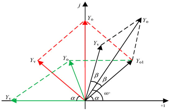
Figure 6.
A phasor diagram of Yo(s) with Yv(s).
Figure 6, when φv = 180° − α, φo = 90°, the critical stability; when φv < 180° − α, φo < 90°, satisfy the stability criterion based on impedance, system stability; but when φv > 180° − α, φo > 90°, the PM is less than zero, at this time when the system is not stable, the results and analysis results of the Bode diagram are basically identical.
3.2. Improve the GVF Control Strategy
From the analysis of Section 2.1, it is known that, to make the system stable, we must guarantee that within fmin~fmax spectrum φv < 180° − α, but to meet the requirements of PM ≥ 30° (φo ≤ 60°), will be expected to make φv ≤ α + 2β. Therefore, an improved control strategy of GVF is proposed, and an all-pass filter is added to the Gf(s) branch to correct the phase of Yv(s) and improve the phase margin of the inverter in the weak grid. Figure 7 shows the equivalent control block diagram of a grid-connected inverter after improved GVF, where GAF(s) is the all-pass filter transfer function, and the expression is:
where, k is the fixed amplitude gain within the full frequency range, which does not affect the amplitude of improved system, k is 1, and a is the phase compensation coefficient [37].
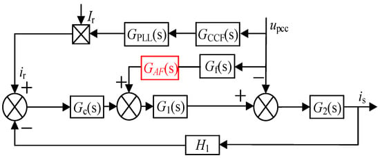
Figure 7.
Equivalent control block diagram of grid-connected inverter after improved GVF.
Figure 8 shows the Bode diagram of the all-pass filter with different values of a under the condition of k = 1.
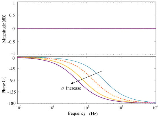
Figure 8.
Bode diagram of all-pass filter with different values of a.
In the above figure, it can be seen that its amplitude in the full frequency range is 0 dB, which can provide 0~180° phase lag compensation in a certain frequency band. Therefore, on the premise of not changing the amplitude, phase correction can be carried out by adjusting the value of parameter a in a specific frequency band.
where, f to compensate frequency points, θ for lag compensation.
In the frequency range where phase lead occurs, the maximum phase of Yv(s) at fmin is 227°, and its phase-frequency curve monotonically decreases in the frequency band from fmin to fmax. Therefore, as long as the phase at this point meets the requirements, the phase at other frequencies can also meet the requirements. Make fmin with phase compensation point, then the lag compensation angle θ = (α + 2β) − 227°. A larger α corresponds to a smaller value of φv that ensures the stability of the system; therefore, for analyzing the worst case, taking α = 53°, thus β = 7°, the system stability is obtained, and leaving at least 30° phase margin requirements for φv ≤ 67° or less. It should at least provide θ = 160° phase compensation. By substituting fmin= 133 Hz and θ = −160° into Formula (12), a = 0.0068 can be obtained.
After adding all feedforward links, the expression of voltage feedforward admittance is:
Figure 9 shows the Bode diagram of Yv_AF(s). Compared with Figure 5, it can be seen that the addition of an all-pass filter only changes the phase of Yv(s) but does not change its amplitude. The phase of Yv_AF(s) at fmin is 66.7°, less than 67°, and the phase in the whole band affected by the GVF phase is less than 67°, meeting the requirement of stability.
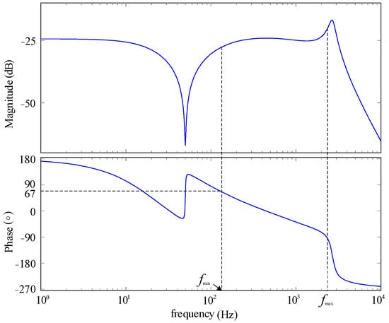
Figure 9.
Bode diagram of Yv_AF(s).
After improving the grid voltage feedforward, the total output admittance of the inverter system can be expressed as:
Figure 10 shows the Bode diagram of Yo_AF(s) with different SCR values. By comparison with Yo(s) in Figure 4, it can be seen that the phase of total output admittance Yo(s) in the frequency band affected by GVF is reduced after the proposed control strategy is added. The phase margin of the system increases from −8.8°, −4.1°, 3.2° and 7.9° to 34.2°, 45.6°, 67.2° and 84° when the SCR is 2, 3, 6, and 10, respectively, which greatly improves the stability of the system.
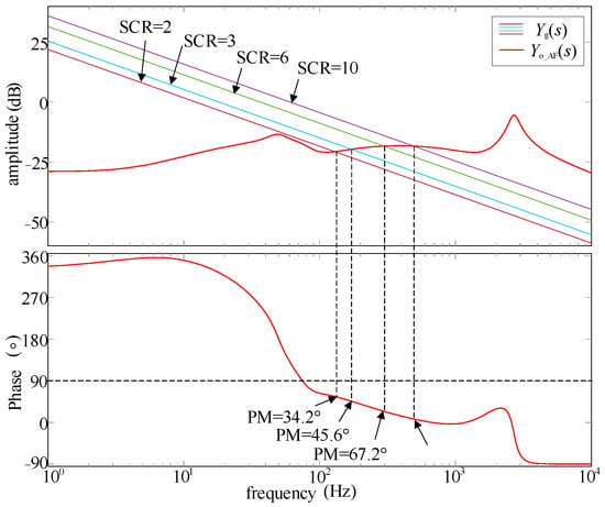
Figure 10.
The Bode diagram of Yo_AF(s).
4. Simulation and Experimental Results
4.1. Simulated Analysis
In order to verify the correctness of the above theoretical analysis and the effectiveness of the proposed strategy, a single-phase LCL grid-connected inverter model was built based on MATLAB/simulink simulation software. The system simulation parameters are shown in Table 1. The simulation model of a single-phase LCL grid-connected inverter system is shown in Figure 11.

Table 1.
Grid-connected inverter simulation parameters.
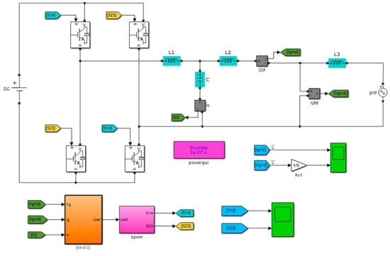
Figure 11.
The simulation model of single-phase LCL grid-connected inverter system.
Firstly, the stability of the inverter system before and after adding GVF is compared. Figure 12 shows the grid-connected current waveform when SCR = 2(Lg = 12.8 mH). When no GVF is added before t = 0.12 s, no oscillation distortion occurs in the grid-connected current. When t = 0.12 s and GVF is added, the grid-connected current oscillates obviously. This indicates that the stability of the grid-connected inverter using CCF-PLL is better without GVF in weak power grids, but becomes unstable after introducing GVF, due to grid current oscillations.
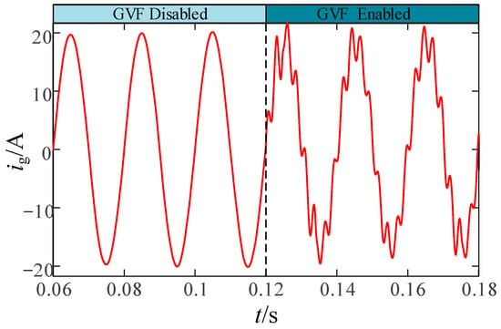
Figure 12.
The ig(t) waveform before and after adding GVF.
According to Figure 4, it is found that traditional GVF results in a phase margin of −8.8° for the inverter system at SCR = 2, indicating system instability. As shown in Figure 13, after adding traditional GVF, the grid-connected current ig(t) exhibits distortion and instability when SCR = 3.1 (Lg = 8.28 mH). As the grid impedance increases, the distortion phenomenon of the current waveform becomes more severe when SCR = 2. The results show that traditional GVF can reduce the stability margin of the grid-connected inverter system using CCF-PLL in a weak grid, and aggravate the system’s instability with the increase in grid impedance.
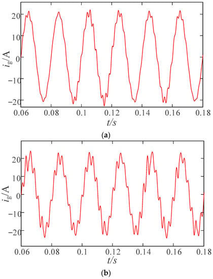
Figure 13.
Waveform of ig(t) adding traditional GVF. (a) SCR = 3.1. (b) SCR = 2.
Figure 10 shows that the improved GVF makes the phase margin of the inverter system 34.2° when SCR = 2, and the system is stable. As shown in Figure 14, after adding the improved GVF, the distortion phenomenon of a grid-connected current waveform is significantly improved. By comparing the simulation results in Figure 12 and Figure 13, it can be seen that the proposed improved GVF strategy effectively improves the adaptability of the grid-connected inverter system to a weak power grid.
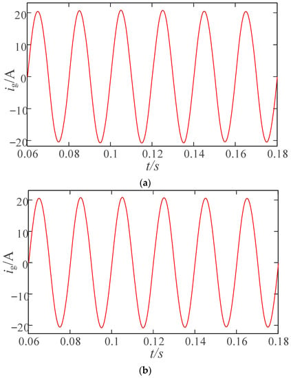
Figure 14.
Waveform of ig(t) when improving GVF is added. (a) SCR = 3.1. (b) SCR = 2.
In addition, FFT analysis was conducted on ig(t) before and after the improved GVF under SCR = 2. As shown in Figure 15, the THD before improvement is 19.59%; there are a large number of harmonics in a grid-connected current, and the largest component of harmonics is mainly concentrated in the frequency band f1(178 Hz)~f2(644 Hz) whose Yo(s) phase is greater than 90°; which is consistent with the theoretical analysis in Section 2.1. After the improvement, the THD is 1.13%, and the harmonic distortion rate of a grid-connected current is reduced by 94.2%, which greatly reduces the harmonic content in f1~f2 bands and improves the stability of the system. The results show that the proposed strategy can ensure the stable operation of the grid-connected inverter when the grid impedance is large.
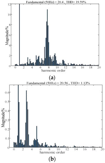
Figure 15.
THD analysis before and after improving GVF. (a) After improving GVF. (b) Before improving GVF.
4.2. Experiment Results
In order to verify the effectiveness of the admittance remodeling strategy of the proposed grid-connected inverter with improved grid voltage feedforward, a single-phase LCL grid-connected inverter model was constructed based on the MT1000 power electronic real-time controller, and the experimental parameters were given in Table 1.
The experimental waveform of a grid current with traditional GVF added is shown in Figure 16. Due to the insufficient system phase margin, the grid current waveform is significantly distorted and contains a large amount of harmonics, resulting in system instability. Figure 17 shows the experimental waveform of a grid current with improved GVF added. After adopting the control strategy with improved GVF, the system has sufficient phase margin, and the grid current waveform is free of significant distortion with a significant reduction in harmonics, leading to an improvement in system stability. The experimental results are consistent with the simulation results.
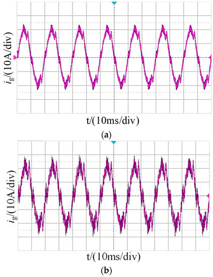
Figure 16.
Experimental waveform of ig(t) before adding improvement GVF. (a) SCR = 3.1. (b) SCR = 2.
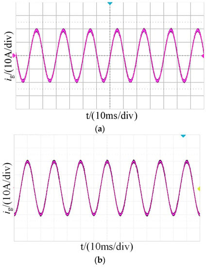
Figure 17.
Experimental waveform of ig(t) after adding improvement GVF. (a) SCR = 3.1. (b) SCR = 2.
5. Conclusions
Through analysis, it was found that conventional GVF makes the total output admittance of a CCF-PLL inverter system phase advance in the middle frequency band, even exceeding 90°, which makes the phase margin negative and seriously affects the stability of the system. Therefore, an improved admittance remodeling strategy of GVF is proposed; and an all-pass filter added to the GVF loop to correct the phase of GVF admittance, so that the phase of the total output admittance of the inverter can meet the stability requirements under a weak grid; and improve the stability of a grid-connected inverter under a weak grid.
Shortcomings: It only improves the system stability problem under the condition of a weak grid. However, under the condition of an extremely weak grid with SCR < 2, the intercept frequency may appear in the low frequency band; and, after improvement, the phase of total output admittance in the low frequency band is still greater than 90°; so there may be instability phenomena. This problem needs to be further optimized in follow-up studies.
Author Contributions
Conceptualization, S.L. and S.H.; methodology, S.H.; formal analysis, D.Z.; writing—original draft preparation, W.H. All authors have read and agreed to the published version of the manuscript.
Funding
This research was funded by National Natural Science Fund, grant number 51977072.
Data Availability Statement
Not applicable.
Conflicts of Interest
The authors declare no conflict of interest.
References
- Wu, W.; Liu, Y.; He, Y.; Chung, H.S.H.; Liserre, M.; Blaabjerg, F. Damping methods for resonances caused by LCL-filter-based current controlled grid-tied power inverters: An overview. IEEE Trans. Ind. Electron. 2017, 64, 7402–7413. [Google Scholar] [CrossRef]
- Yu, L.; Sun, H.; Zhao, B.; Xu, S.; Zhang, J.; Li, Z. ShiyunShort Circuit Ratio Index Analysis and Critical Short Circuit Ratio Calculation of Renewable Energy Grid-connected System. CSEE 2022, 42, 919–929. [Google Scholar]
- Chen, X.; Zhang, Y.; Wang, S.; Chen, J.; Gong, C. Impedance-phased dynamic control method for grid-connected inverters in a weak grid. IEEE Trans. Power Electron. 2016, 32, 274–283. [Google Scholar] [CrossRef]
- Li, M.; Zhang, X.; Guo, Z.; Wang, J.; Wang, Y.; Lib, F.; Zhao, W. The Control Strategy for the Grid-Connected Inverter through Impedance Reshaping in q-Axis and its Stability Analysis Under a Weak Grid. IEEE J. Emerg. Sel. Top. Power Electron. 2020, 9, 3229–3242. [Google Scholar] [CrossRef]
- Huanhai, X.; Wei, D.; Xiaoming, Y.; Deqiang, G.; Kang, W.; Huan, X. Generalized Short Circuit Ratio for Multi Power Electronic Based Devices Infeed to Power Systems. CSEE 2016, 36, 6013–6027. [Google Scholar]
- Fang, T.; Zhang, H.; Wu, H.; Zhang, Y. Robustness Enhancement of Coping with Dual Factors for Grid-Connected Inverter in Weak Grid Based on Synthesis-Admittance-Phasor Scheme. IEEE Trans. Ind. Electron. 2022, 14, 754–769. [Google Scholar] [CrossRef]
- Du, Y.; Sun, Q.; Yang, X.; Cui, L.; Zhang, J.; Wang, F. Adaptive Virtual Impedance of Grid-Tied Inverters to Enhance the Stability in a Weak Grid. J. Electr. Eng. Technol. 2019, 14, 1235–1246. [Google Scholar] [CrossRef]
- Xu, J.; Qian, Q.; Zhang, B.; Xie, S. Harmonics and stability analysis of single-phase grid-connected inverters in distributed power generation systems considering phase-locked loop impact. IEEE Trans. Sustain. Energy 2019, 10, 1470–1480. [Google Scholar] [CrossRef]
- Ali, Z.; Christofides, N.; Hadjidemetriou, L.; Kyriakides, E. Multi-functional distributed generation control scheme for improving the grid power quality. IET Power Electron. 2019, 12, 30–43. [Google Scholar] [CrossRef]
- Fang, J.; Li, X.; Li, H.; Tang, Y. Stability Improvement for Three-Phase Grid-Connected Converters Through Impedance Reshaping in Quadrature-Axis. IEEE Trans. Power Electron. 2018, 33, 8365–8375. [Google Scholar] [CrossRef]
- Xu, J.; Qian, Q.; Xie, S.; Zhang, B. Grid-voltage feedforward based control for grid-connected LCL-filtered inverter with high robustness and low grid current distortion in weak grid. In Proceedings of the 2016 IEEE Applied Power Electronics Conference and Exposition, IEEE, Long Beach, CA, USA, 20–24 March 2016; pp. 1919–1925. [Google Scholar]
- Guo, X.; Guerrero, J.M. Abc-frame complex-coefficient filter and controller based current harmonic elimination strategy for three-phase grid connected inverter. Mod. Power Syst. Clean Energy 2016, 4, 87–93. [Google Scholar] [CrossRef]
- Lee, K.J.; Lee, J.P.; Shin, D.; Yoo, D.W.; Kim, H.J. A novel grid synchronization PLL method based on adaptive low-pass notch filter for grid-connected PCS. IEEE Trans. Ind. Electron. 2013, 61, 292–301. [Google Scholar] [CrossRef]
- Tu, C.; Gao, J.; Li, Q. Research on adaptability of grid-connected inverter with complex coefficient-filter structure phase locked loop to weak grid. Trans. Electrotech. Soc. 2020, 35, 2632–2642. [Google Scholar]
- Lin, Z.; Chen, Z.; Yajuan, L.; Bin, L.; Jinhong, L.; Bao, X. Phase-reshaping strategy for enhancing grid-connected inverter robustness to grid impedance. IET Power Electron. 2018, 11, 1434–1443. [Google Scholar] [CrossRef]
- Lin, Z.; Ruan, X.; Wu, L.; Zhang, H.; Li, W. Multi resonant Component-Based Grid-Voltage-Weighted Feedforward Scheme for Grid-Connected Inverter to Suppress the Injected Grid Current Harmonics under Weak Grid. IEEE Trans. Power Electron. 2020, 9, 9784–9793. [Google Scholar] [CrossRef]
- Yan, Q.; Wu, X.; Yuan, X.; Geng, Y. An improved grid-Voltage feedforward strategy for high-power three-phase grid-connected inverters based on the simplified repetitive predictor. IEEE Trans. Power Electron. 2016, 31, 3880–3897. [Google Scholar] [CrossRef]
- Xu, J.; Xie, S.; Zhang, B.; Qian, Q. Robust grid current control with impedance-phase shaping for LCL-filtered inverters in weak and distorted grid. IEEE Trans. Power Electron. 2018, 33, 10240–10250. [Google Scholar] [CrossRef]
- Wang, X.; Qin, K.; Ruan, X.; Pan, D.; He, Y.; Liu, F. A robust grid-voltage feedforward scheme to improve adaptability of grid-connected inverter to weak grid condition. IEEE Trans. Power Electron. 2020, 36, 2384–2395. [Google Scholar] [CrossRef]
- Yang, S.; Tong, X.; Yin, J.; Wang, H.; Deng, Y.; Liu, L. BPF-based grid voltage feedforward control of grid-connected converters for improving robust stability. J. Power Electron. 2017, 17, 432–441. [Google Scholar] [CrossRef]
- Xu, J.; Xie, S.; Qian, Q.; Zhang, B. Adaptive feedforward algorithm without grid impedance estimation for inverters to suppress grid current instabilities and harmonics due to grid impedance and grid voltage distortion. IEEE Trans. Ind. Electron. 2017, 64, 7574–7586. [Google Scholar] [CrossRef]
- Khajeh, K.G.; Farajizadeh, F.; Solatialkaran, D. A full-feedforward technique to mitigate the grid distortion effect on parallel grid-tied inverters. IEEE Trans. Power Electron. 2022, 37, 8404–8419. [Google Scholar] [CrossRef]
- Xu, J.; Xie, S.; Tang, T. Improved control strategy with grid-voltage feedforward for LCL-filter-based inverter connected to weak grid. IET Power Electron. 2014, 7, 2660–2671. [Google Scholar] [CrossRef]
- Gao, J.; Tu, C.; Guo, Q.; Xiao, F.; Jiang, F.L.; Lu, B. Impedance Reshaping Control Method to Improve Weak Grid Stability of Grid-Connected Inverters. In Proceedings of the IECON 2020 the 46th Annual Conference of the IEEE Industrial Electronics Society, Singapore, 19–21 October 2020; pp. 1342–1346. [Google Scholar]
- Li, X.; Fang, J.; Tang, Y.; Wu, X. Robust design of LCL filters for single-current-loop-controlled grid-connected power converters with unit PCC voltage feedforward. IEEE J. Emerg. Sel. Top. Power Electron. 2017, 6, 54–72. [Google Scholar] [CrossRef]
- Chen, B.; Zeng, C.B.; Miao, H.; Hong, C. Improved voltage feedforward method for improving robust stability of grid-connected inverters in weak grids. J. Electr. Power Sci. Technol. 2021, 36, 118–124. [Google Scholar]
- Zeng, C.; Wang, H.; Li, S.; Miao, H. Grid-voltage-feedback active damping with lead compensation for LCL-type inverter connected to weak grid. IEEE Access 2021, 9, 106813–106823. [Google Scholar] [CrossRef]
- Wang, H.; Zeng, C.; Miao, H. A phase compensation algorithm of a grid-connected inverter based on a feedforward multi-resonant grid voltage. Power Syst. Prot. Control 2021, 49, 81–89. [Google Scholar]
- Wang, G.; Du, X.; Shi, Y.; Yang, Y.; Sun, P.; Li, G. Effects on oscillation mechanism and design of grid-voltage feedforward in grid-tied converter under weak grid. IET Power Electron. 2019, 12, 1094–1101. [Google Scholar] [CrossRef]
- Xie, Z.; Chen, Y.; Wu, W.; Gong, W.; Guerrero, J.M. Stability enhancing voltage feed-forward inverter control method to reduce the effects of phase-locked loop and grid impedance. IEEE J. Emerg. Sel. Top. Power Electron. 2020, 9, 3000–3009. [Google Scholar] [CrossRef]
- Pang, B.; Li, F.; Dai, H.; Nian, H. High Frequency Resonance Damping method for voltage source converter based on voltage feedforward control. Energies 2020, 13, 1591. [Google Scholar] [CrossRef]
- Yang, D.; Ruan, X.; Wu, H. Impedance shaping of the grid-connected inverter with LCL filter to improve its adaptability to the weak grid condition. IEEE Trans. Power Electron. 2014, 29, 5795–5805. [Google Scholar] [CrossRef]
- Xia, W.; Kang, J. Stability of LCL-filtered grid-connected inverters with capacitor current feedback active damping considering controller time delays. J. Mod. Power Syst. Clean Energy 2017, 5, 584–598. [Google Scholar] [CrossRef]
- Zhu, K.; Sun, P.; Zhou, L.; Du, X.; Luo, Q. Frequency-Division Virtual Impedance Shaping Control Method for Grid-Connected Inverters in a Weak and Distorted Grid. IEEE Trans. Power Electron. 2020, 35, 8116–8129. [Google Scholar] [CrossRef]
- Wang, H.; Chen, Y.; Wu, W.; Liao, S.; Wang, Z.; Li, G.; Guo, J. Impedance Reshaping Control Strategy for Improving Resonance Suppression Performance of a Series-Compensated Grid-Connected System. Energies 2021, 14, 2844. [Google Scholar] [CrossRef]
- Sun, J. Impedance-based stability criterion for grid-connected inverters. IEEE Trans. Power Electron. 2011, 26, 3075–3078. [Google Scholar] [CrossRef]
- Xue, T.; Sun, P.; Xu, Z.; Luo, Q. Feedforward phase compensation method of LCL grid-connected inverter based on all-pass filter in weak grid. IET Power Electron. 2020, 13, 4407–4416. [Google Scholar] [CrossRef]
Disclaimer/Publisher’s Note: The statements, opinions and data contained in all publications are solely those of the individual author(s) and contributor(s) and not of MDPI and/or the editor(s). MDPI and/or the editor(s) disclaim responsibility for any injury to people or property resulting from any ideas, methods, instructions or products referred to in the content. |
© 2023 by the authors. Licensee MDPI, Basel, Switzerland. This article is an open access article distributed under the terms and conditions of the Creative Commons Attribution (CC BY) license (https://creativecommons.org/licenses/by/4.0/).