Article

Communication-Free Interleaving Control of Parallel-Connected DC-DC Converters

1
Key Laboratory of Photovoltaic Technology of Guangdong Province, School of Physics, Sun Yat-sen University, Guangzhou 510275, China
2
School of Intelligent Systems Engineering, Shenzhen Campus of Sun Yat-sen University, Shenzhen 518107, China
*
Author to whom correspondence should be addressed.
Electronics 2023, 12(9), 2111; https://doi.org/10.3390/electronics12092111
Submission received: 19 March 2023 / Revised: 26 April 2023 / Accepted: 28 April 2023 / Published: 5 May 2023
(This article belongs to the Section Power Electronics)

Abstract

:
Parallel-connected converters are commonly used in applications such as DC microgrids. The presence of multiple converters allows for the use of the interleaving technique to minimize bus ripple. Most existing interleaving methods rely on communication lines, which are unsuitable for distributed scenarios. This paper presents a method that requires no communication line. The elimination of communication lines reduces the system’s complexity and cost while improving its reliability. We provide an analytical guarantee of stability and validate the control method using phasor simulation and an experimental prototype with three 24 V to 8 V DC-DC buck converters connected in parallel. Measurements show that the proposed method allows the parallel system to maintain an interleaved state in the face of load steps and converters plugged in and out.

1. Introduction

Systems of parallel-connected converters are suitable for a variety of applications. In new energy microgrid systems, photovoltaic arrays [1,2,3,4,5], wind turbines [6], and energy storage devices [7,8] are often connected in parallel to the DC bus [9,10,11]. In fast-charging systems [12], parallel connections are often used to reduce current stress [13]. Parallel systems are also used for DC microgrids in aircraft [14,15], spacecraft, ships [16,17,18,19], and electric vehicles [20,21]. In microprocessor power management, interleaved parallel connections are also commonly used to reduce ripple. Interleaving control offers several advantages to parallel systems, including relaxed filter capacitor requirements, reliability, modularity, and power ratings.
State-of-the-art interleaving control methods have focused on communication-based methods. The communication-based methods use a global communication bus or multiple communication lines connecting neighboring converters to exchange phase information. The phase of each converter is assigned by an upper controller (centralized method) or is adjusted by the local controller according to the phases of the neighboring converters (decentralized method). One work [22] presents a decentralized method in which the communication lines are connected in series; such a communication structure does not support the plug-and-play feature. The authors of [23] present the use of a single communication bus to achieve decentralized interleaving control, which can only handle symmetric converters. The method in [24] relies on communication between neighboring converters to achieve interleaving control and is limited to symmetric converters. The study in [25] presents a multilevel multiphase converter using decentralized interleaving control, which relies on communication between neighboring cells. The work presented in [26] is similar to [24] in which communication between neighboring converters is used. The research in [27] uses one communication line to sample the total current of the parallel system. The authors of [28] apply a decentralized method to a serial–parallel converter, using a communication scheme similar to [25]. The communication-based methods are limited by the communication bandwidth, number of ADC channels, number of PWM channels, and computational resources, making it challenging to scale them to applications that use a large number of converters. The existence of communication lines also brings disadvantages in terms of cost and reliability. Many communication methods are based on communication between neighboring converters, and such a structure has a single point of failure.
One approach to addressing the aforementioned drawbacks of communication-based methods is to use a commutation-free method. There are few previous research studies that used communication-based methods. Reference [29] presents a communication-free method based on the dynamics of coupled nonlinear oscillators. However, it requires a high sample rate and control frequency. Reference [30] uses a gradient descent method to achieve switching interleaving. However, its model is complex and requires precise compensation of the sampling latency.
In this paper, we propose a communication-free interleaving control method. The proposed method has the following key features:
(1)
No requirement for communication lines.
Each controller uses only local current and bus voltage as feedback and performs the phase-shifting control independently.
(2)
Compatibility with the current sharing control.
The proposed method relies on PWM frequency adjustment to achieve phase shifting and does not influence current-sharing controls, such as the droop control.
(3)
Compatibility with non-uniform converter parameters.
The proposed method can adapt to non-uniform converter parameters, including input voltage, filter parameters, and controller clocks.
(4)
Plug-and-play feature.
The decentralized nature of the proposed method allows the converter to plug in or plug out of the power bus without informing other converters.
Compared with existing communication-free methods, the innovative contributions of this work are highlighted as follows:
(1)
Relaxed sampling requirements.
The proposed method does not require a high sampling rate and accurate sample timing. The sampling rate of four times the switching frequency and the sampling timing are fixed.
(2)
Simple control implementation.
The proposed method does not require additional models, pre-computed lookup tables, or computationally intensive optimization algorithms.
(3)
Elimination of higher harmonics.
The proposed method can eliminate the first and optionally higher harmonics. The elimination of higher harmonics requires a higher sample rate.
The structure of this paper is as follows. Section 2 describes the proposed control method. Section 3 provides an analysis of the stability of the proposed method. Section 4 provides the results of experimental measurements to verify the efficacy of the proposed method. Section 5 concludes the article.

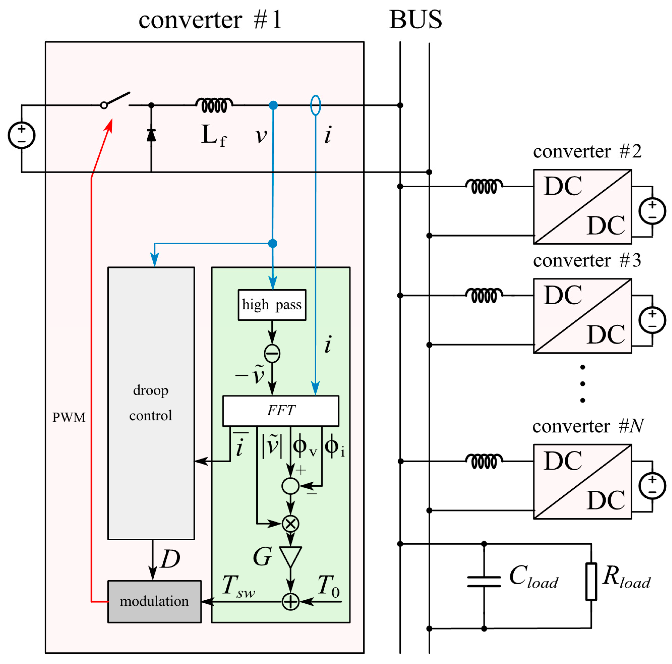
2. System Description and Control Method

In this section, we describe the system of parallel-connected converters, the principle of communication-free interleaving control, the implementation of the principle, and its potential for canceling higher harmonics.

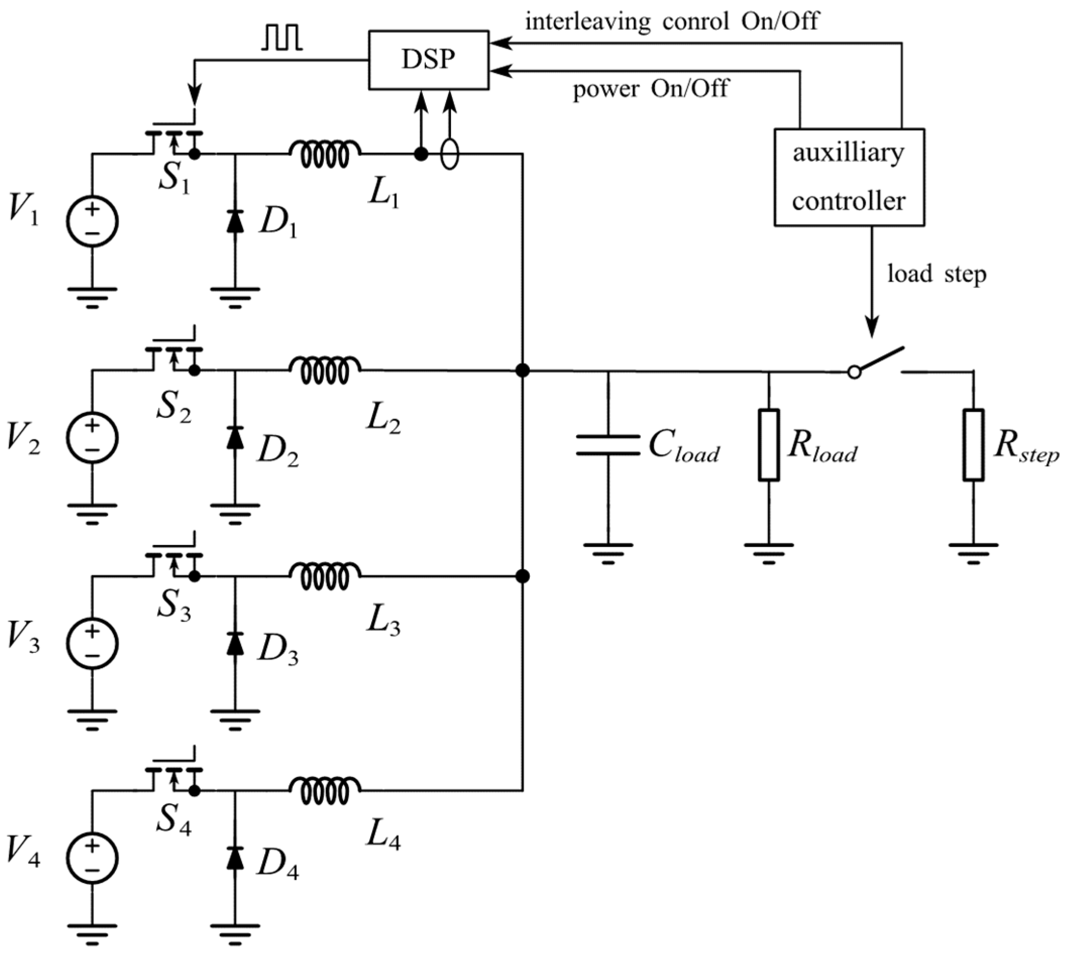
2.1. System of Parallel-Connected Converters

The system of parallel-connected converters considered in this paper is shown in Figure 1. Multiple DC-DC converters are connected to a DC bus to supply power to a common load. Each converter uses an independent output filter inductor and shares filter capacitors. Each converter uses an independent controller. The feedback available to the controllers comprises the bus voltage and output current. These DC converters can be of different topologies. As an example, the buck converter is used for converter number one in the figure. The converters are controlled using PWM with the same frequency. Voltage regulation and current distribution are achieved through duty cycle control. In the remainder of this paper, we refer to the above system as the parallel system. The proposed control method aims to achieve switching interleaving in the parallel system through the independent phase-shifting control of each converter.

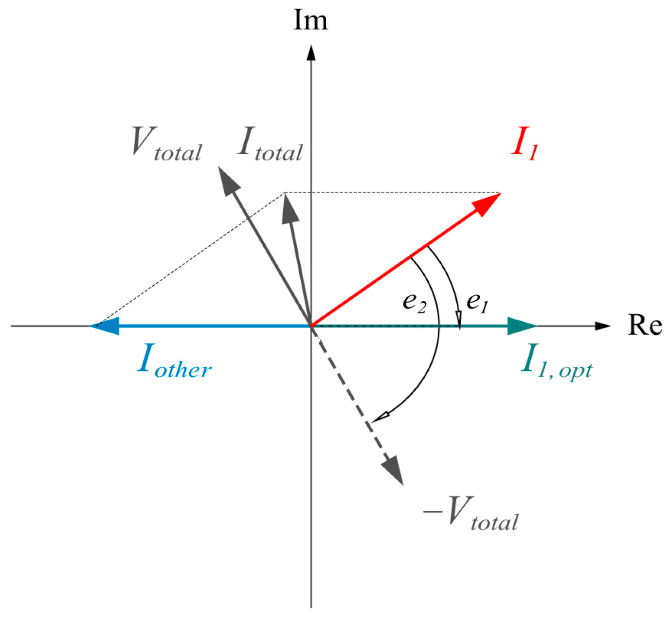
2.2. Principle of Interleaving Control

Since the first harmonic is dominant, we use a phasor diagram to describe the first harmonic of the current and voltage ripple on the bus, shown in Figure 2. Initially, the switching frequencies of these converters are the same, so the phasors remain constant. At this point, we allow one of the converters to adjust its current phasor I 1 to reduce the total current ripple I t o t a l . The optimal position of I 1 , marked as I 1 , o p t , should be located opposite to I o t h e r , which is the sum of the current ripples generated by other converters. If I o t h e r is measured, one can easily calculate I 1 , o p t and set up a controller to drive I 1 towards I 1 , o p t . However, I o t h e r and I t o t a l cannot be measured locally. One possible solution is to use V t o t a l to replace I o t h e r , in other words, to use − V t o t a l to replace I 1 , o p t . By defining the controller input as
e 1 = I 1 I 1 , o p t   e 2 = I 1 V t o t a l e 1 , e 2 π , π
We can see from Figure 2 that e 1 and e 2 have the same sign. Therefore, when using a proportional controller, using either e 1 or e 2 as the controller input will drive I 1 in the same direction. Note that a discontinuous jump in e 2 occurs when I 1 crosses I 1 , o p t . To eliminate this discontinuity, e 2 is multiplied with | V t o t a l |, which is close to zero when I 1 is close to I 1 , o p t . From the above analysis, we provide the following controller:
ϕ ˙ i = G V t o t a l ϕ i ϕ v total  
where G is a tunable gain, ϕ i is the phase of the output current, and ϕ v total is the phase of the bus voltage inverted. An implementation of the above controller is shown in Figure 1.

2.3. Higher Harmonics

The above analysis only considers the first harmonic. When more than three converters are connected on the bus, higher harmonics can be considered. As an example, Figure 3 illustrates the phasor diagrams and waveforms of a parallel system with three or four identical converters. In case I, there is only one possible interleaving state in which each converter is shifted by 120°. The first and the second harmonics are both canceled. When there are four converters, case II and case III are both possible states that cancel the first harmonic. However, the second harmonic in case II is synchronized rather than interleaved, resulting in a large bus harmonic. One solution to this problem is to set up a second-harmonic controller using (2) based on the second harmonic. The output of the second-harmonic controller is weighted and averaged with the output of the first-harmonic controller. Since the first harmonic is dominant in the ripple, canceling the first harmonic is the priority. By assigning a small weight to the second-harmonic controller, one can make the second-harmonic controller take effect only when the first harmonic is mostly canceled.

2.4. Method Compatibility

Since the proposed method is to be applied in parallel systems, it is of significant importance for the method to be compatible with current-sharing controls. Current-sharing controls are concerned with the DC components of the current and voltage, and the proposed method only changes the phases of the AC components. In principle, the proposed method does not influence current-sharing controls. However, with interleaving control to eliminate bus ripple, each converter can allow for a larger current ripple, which can have an impact on proper DC sampling. Filtering may be required to ensure correct current sampling. However, the proposed method requires FFT operation to acquire current phases, whereas the DC components of the current can be obtained as a side product. Therefore, no additional filtering is required for current sensing. This optimization is included in Figure 1 and is used in the following simulation and experiments.
The proposed method is generalizable for a variety of converter types but has the following limitations. The proposed method relies on frequency variation to perform phase shifting. Therefore, the converter itself must achieve voltage regulation only through duty cycle variations to avoid conflicts. This means that the proposed method is limited to fixed-frequency converters. The proposed method requires the output current to be continuous before it is filtered by the output capacitor, and it cannot be applied directly to converter types with discontinuous output current, such as boost, sepic, flyback, forward, etc. To apply the proposed method to such converters, an extra filter inductor is required, as shown in Figure 1. The existence of an extra filter inductor will change the dynamics of the converter significantly. This issue is beyond the scope of this work and will be considered in future studies. At this stage, we regard the requirement for continuous output current as a limitation.

3. Stability Analysis

3.1. Proof of Stability

In this section, we analyze the stability of the proposed control method from a global perspective. We consider the case of all converters performing phase-shifting control simultaneously and prove that the derivative of the bus harmonic with respect to time is nonpositive.
Consider the parallel system with N converters connected, shown in Figure 4, and denote the output current harmonic of the kth converter as
I k = A k e i ϕ k
where A k is the magnitude of the current harmonic and ϕ k is the phase of the current harmonic.
The harmonic of bus current and its magnitude is
I t o t a l = k = 1 N I k = k = 1 N A k e i ϕ k
and
I t o t a l 2 = k = 1 N A k cos ϕ k 2 + k = 1 N A k sin ϕ k 2
Since all converters are performing phase-shifting control simultaneously, all ϕ k values vary with time. Taking the derivative for time, we have
d ( I t o t a l 2 ) d t = 2 k = 1 N A k cos ϕ k k = 1 N ϕ ˙ k A k sin ϕ k   + 2 k = 1 N A k sin ϕ k k = 1 N ϕ ˙ k A k cos ϕ k    
Since | I t o t a l | is only related to the relative phase of the converters, we can rotate the coordinate system without breaking the above relationships. To simplify the analysis, we rotate the coordinate system so that the phase of I t o t a l is −π, as Figure 4 shows. The rotation applies the following constraints to Formula (6):
R e I t o t a l = k = 1 N A k cos ϕ k = I t o t a l
I m I t o t a l = k = 1 N A k sin ϕ k = 0
The second term of Equation (6) becomes zero, and it becomes
d ( I t o t a l 2 ) d t = I t o t a l k = 1 N ϕ ˙ k A k sin ϕ k  
Substituting the controller from (2) into ϕ ˙ k , we have
d ( I t o t a l 2 ) d t = I t o t a l k = 1 N G ϕ k θ l o a d A k sin ϕ k   = G I t o t a l k = 1 N ϕ k A k sin ϕ k θ l o a d k = 1 N A k sin ϕ k   = G I t o t a l k = 1 N ϕ k A k sin ϕ k  
where θ l o a d is the phase delay caused by the resistive load and the filter capacitor. Since ϕ k sin ϕ k is nonnegative, if G is negative, we have
d I t o t a l 2 d t 0
Equation (11) means that I t o t a l is nonincreasing. The equality in (11) holds when I t o t a l = 0 or ϕ k = 0 or π. The case of I t o t a l = 0 represents a complete cancellation of the harmonic. The case in which all phases are equal means that all the converters are synchronized and I t o t a l obtains a maximum value. Since I t o t a l is nonincreasing, this state is unstable. The case in which phase 0 and π are present is observed only in some special cases. For example, in the case in which only two converters with different currents are connected to the bus, it is impossible to achieve I t o t a l = 0 , whereas ϕ 1 = 0 and ϕ 2 = π represent the optimal solution.

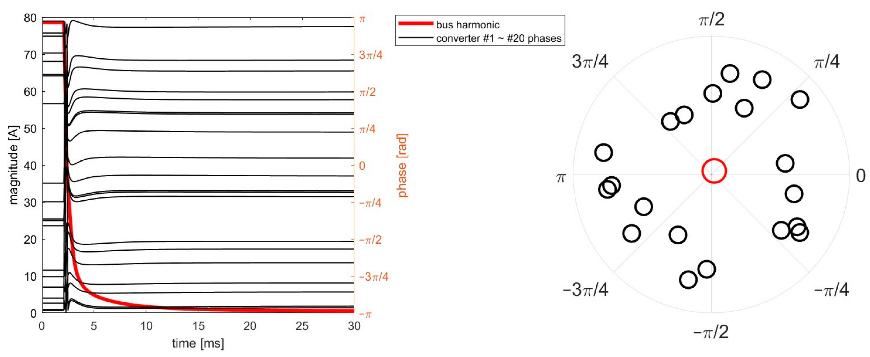
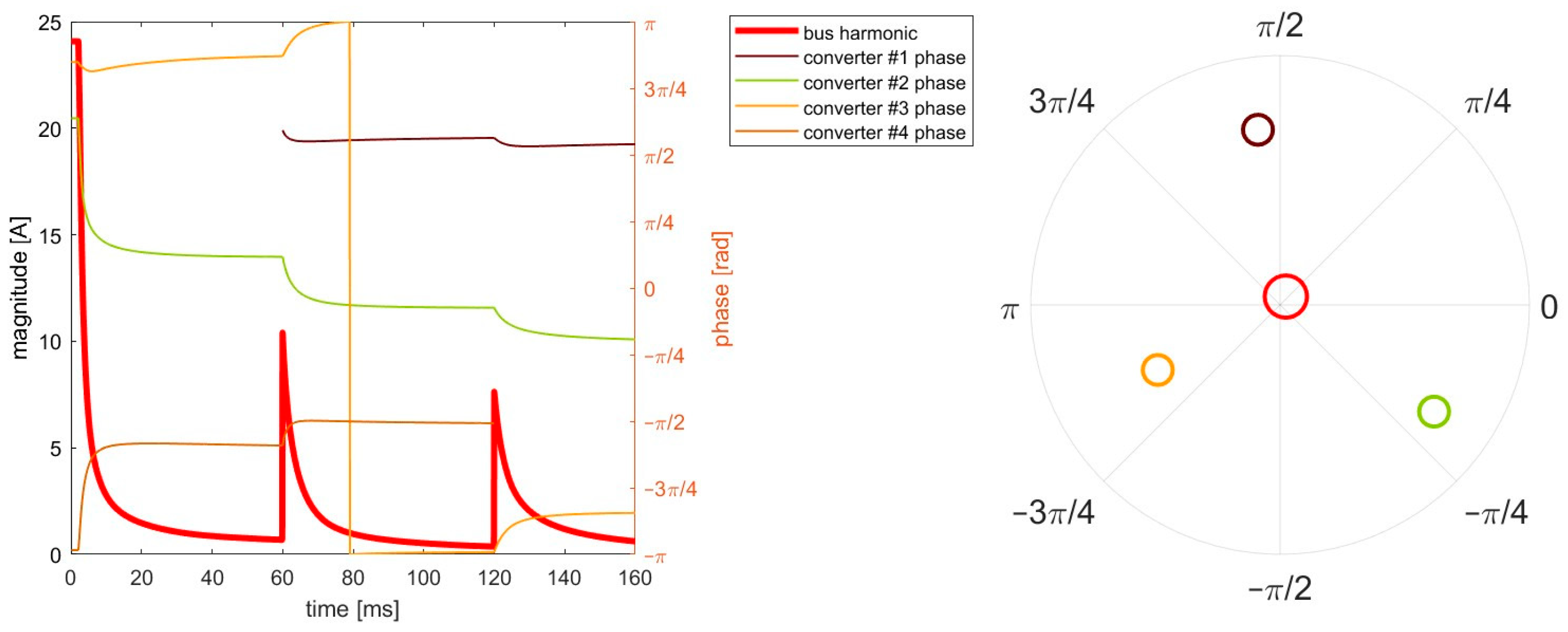
3.2. Phasor Simulation

To further prove the efficacy of the control method, we performed a phasor simulation using the above model. The converter phases are initialized randomly and updated according to the proposed controller with a time step of 0.1 ms. The phasors of the first harmonics of the voltage bus are calculated and recorded. Scenarios of asymmetric converters and converter addition and subtraction are included in the simulation. The simulation results are presented as curves of current ripple magnitudes and phasor diagrams of the final state.

3.2.1. Asymmetric Converters

First, three converters with different current harmonics are connected to the bus. The first harmonic of the current ripple is included. The magnitude and phase of the harmonic are initialized randomly. The simulation result is presented in Figure 5. The phase-shifting control starts at t = 2 ms. The curve of the magnitude of the bus harmonic monotonically decreases, aligned with the nonincreasing nature of the bus harmonic mentioned previously. The phasor diagram of the steady state shows that the first harmonic is canceled, proving that the proposed control method can be adapted to the asymmetric scenario. Next, the parallel system is scaled up to twenty converters. The result is presented in Figure 6. Though the converters are not perfectly interleaved at the final state, the bus ripple is mostly canceled. The curve of the bus harmonic magnitude monotonically decreases with time, aligned with the nonincreasing nature mentioned above. The result proves that the proposed method can be adapted to a system with a large number of converters.

3.2.2. Converter Addition and Subtraction

The transient when a converter is added or removed from the bus is simulated and is shown in Figure 7. The parallel system initially has three converters connected. The phase-shifting control starts at t = 2 ms, and the bus harmonics reduce rapidly. A converter (converter number one) with a random initial phase is added to the bus at t = 60 ms. The addition of the converter breaks the interleaving state, and the bus ripple increases immediately. Afterward, the four converters adjust their phases, and the bus harmonic is gradually reduced to the previous level. At t = 120 ms, converter number four is removed from the bus. The pattern of converter subtraction is similar to that of converter addition. The bus harmonic rises immediately and reduces gradually. This simulation shows the plug-and-play feature of the proposed method.

3.3. Converter Simulation

To further validate the efficacy and compatibility of the proposed method and to provide an expectation for the experiment, a converter-level simulation is set up using MATLAB Simulink. The simulation includes four parallel-connected buck converters stepping down from 24 V to 8 V at 10 kHz. Each converter is controlled by its own controller. Each controller samples the converter current and bus voltage as feedback and generates a PWM signal for the power stage. The duty cycle of the PWM is determined using the droop control method, whereas the PWM frequency is determined using the proposed method. The parameters used in the simulation are similar to those used in the experiment and are listed in Table 1.

3.3.1. Startup of Phase-Shifting Control

Figure 8 shows the waveforms of the bus voltage, converter current, and total current during the startup process of the phase-shifting control. The initial phases of the converters are ϕ 1 = 0 ° ,   ϕ 2 = 36 ° ,   ϕ 3 = 72 ° , and ϕ 4 = 108 ° , resulting in a large bus voltage ripple around 2 V. The phase-shifting control begins at t = 0.04 s. The bus voltage ripple reduces rapidly and reaches a steady state after a 10 ms transient. The converter current details are shown in Figure 8c, where the converters are phase-shifted by 1/4 of the switching cycle, or by 90°. The DC component of the bus voltage remains unchanged during the process, and the DC component of the converter current is balanced, indicating that the proposed method is compatible with voltage regulation and current-sharing control.

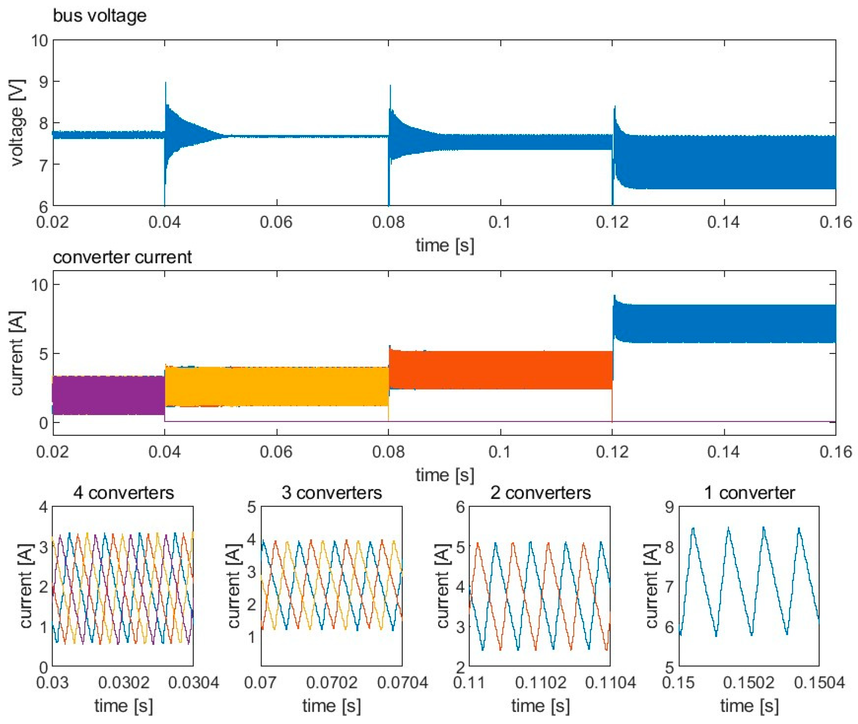
3.3.2. Unit Addition and Subtraction
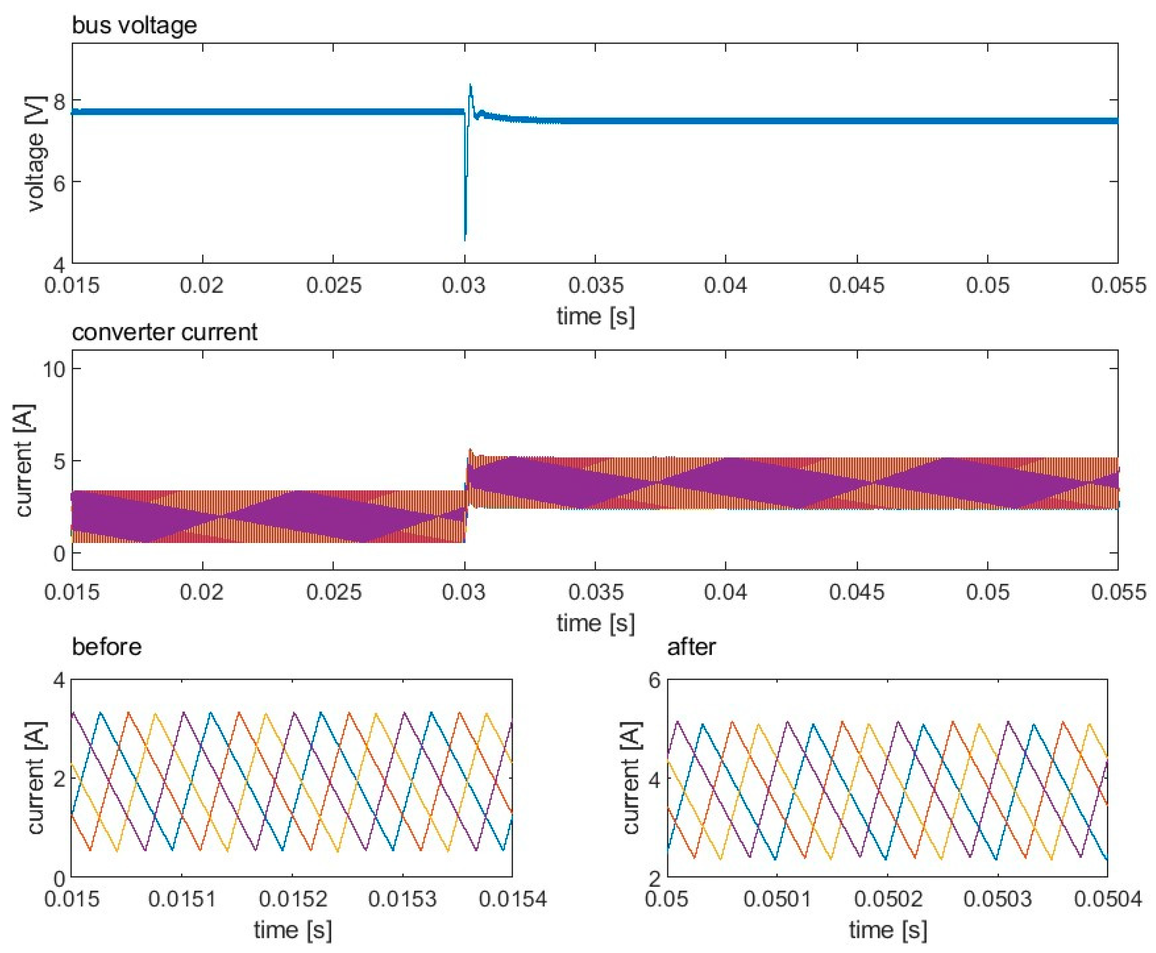
Figure 9 shows the waveforms of the bus voltage and converter current during unit addition. The number of converters gradually increases from one to four. Figure 10 shows the waveforms of the bus voltage and converter current during unit subtraction in which the number of converters decreases from four to one. As can be seen in Figure 9 and Figure 10, the variation in the converter number breaks the previous interleaving state and immediately causes a large ripple. The bus ripple then gradually reduces, and the parallel system recovers to the interleaving state after a transient of around 13 ms. Since the load remains constant, the current of each converter decreases every time a new converter is added to the bus and increases when a converter is removed from the bus. The current sharing is maintained well when the number of converters varies, indicating that the proposed method is compatible with current-sharing control and supports the plug-and-play feature.
For both Figure 9 and Figure 10, the minimum bus voltage ripple is achieved at three converters. This is because when the three interleaved buck converters operate at a conversion ratio of 1/3, the bus ripple is, in principle, zero. The remaining ripple in the simulation results from a deviation in the conversion ratio due to droop control and phase deviation due to the steady error of the proposed method.

3.3.3. Load Step

Figure 11 shows the scenario of a load step in which the load changes from 1 Ω to 0.5 Ω . Since the load step mainly affects the DC component of the current and has less effect on the AC component, the bus voltage recovers within 10 ms. The phases of the converters are barely perturbed during the load step. Therefore, the interleaving state is mostly maintained during the load step.

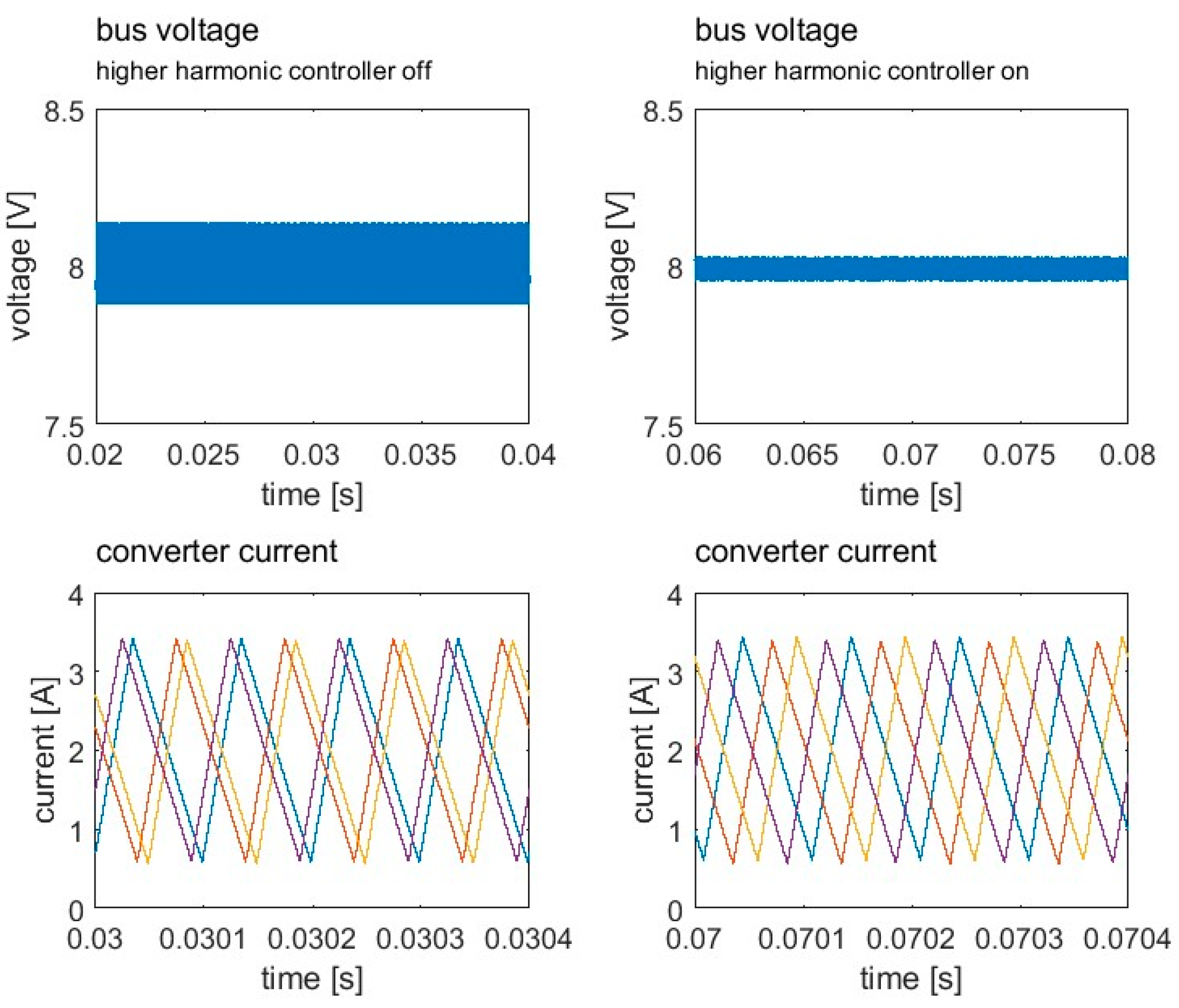
3.3.4. Higher Harmonic Controller

To validate the efficacy of the higher harmonic controller, a comparison of the two steady states is shown in Figure 12. The left panel of Figure 12 is close to the previously mentioned Figure 3 case II in which the first harmonic is canceled but the second harmonic is synchronized, resulting in a ripple of 0.24 V. The right panel of Figure 12 is close to Figure 3 case III in which both the first and the second harmonics are canceled, resulting in a ripple of 0.07 V. This comparison shows the efficacy of the higher harmonic controller. Though the higher harmonic controller can offer further ripple elimination, it may require more accurate voltage ripple sampling since the second harmonic has a smaller magnitude. Meanwhile, the ripple of 0.24 V on the left already presents a good ripple cancelation since the ripple of a single converter is 1.31 V.

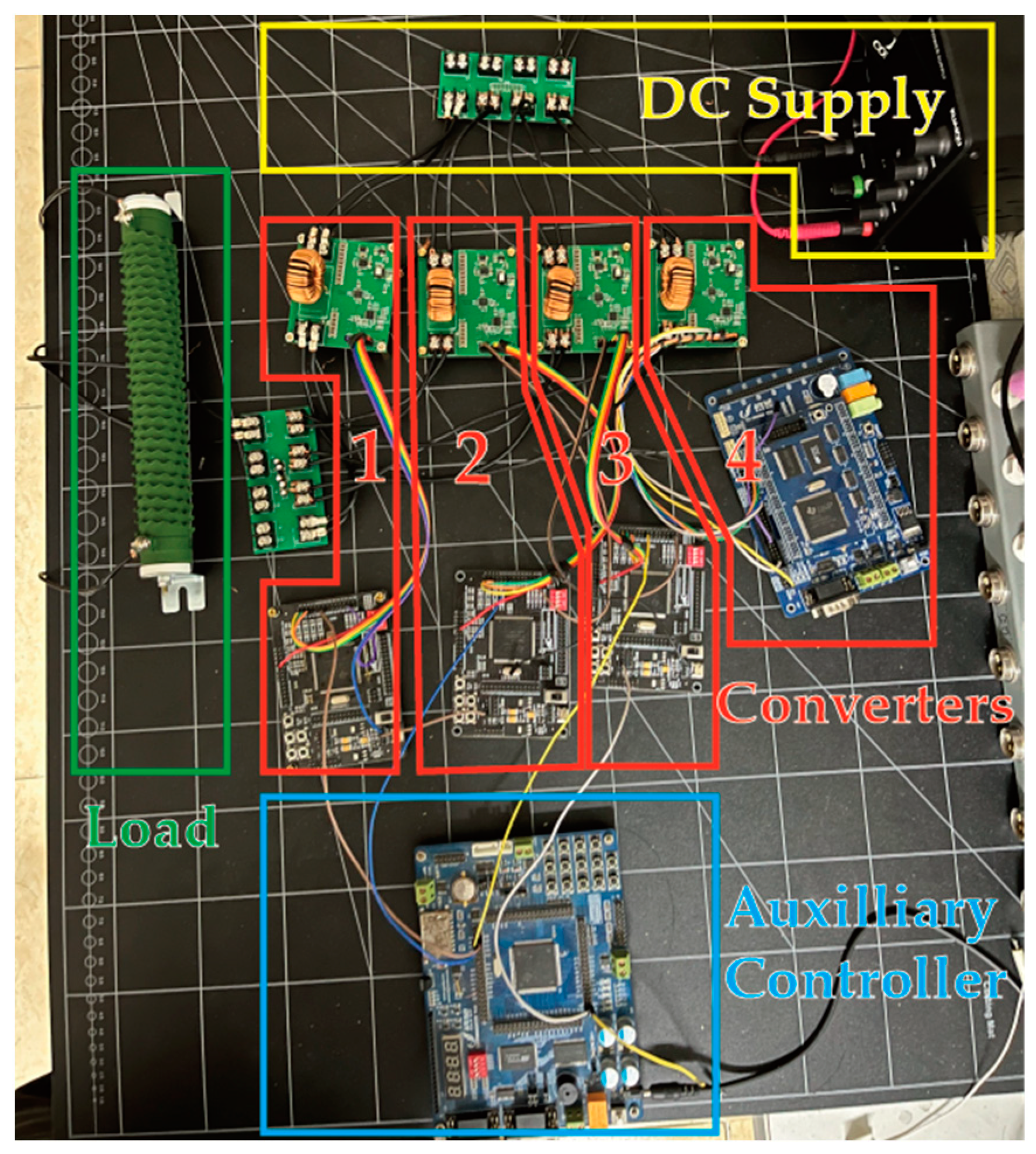
4. Experimental Validation

To validate the proposed controller, a hardware prototype of the parallel-connected buck converters was built. The diagram of the prototype is provided in Figure 13, and a photo of the prototype is shown in Figure 14. The output of all converters is connected in parallel across a filter capacitor and a resistive load. Each converter has an independent DSP controller which samples the inductor current and bus voltage as feedback. An auxiliary controller is used to handle the switching of the converter power and phase-shifting control, as well as to perform the load step. The parameters of the prototype are listed in Table 2. The phase-shifting gain G is selected empirically.
Four experiments were conducted to validate the proposed method, including (1) the startup of phase-shifting control; (2) unit addition; (3) unit subtraction; (4) a load step. The bus ripple and converter current in these experiments are presented and compared with the simulation in the following subsections.

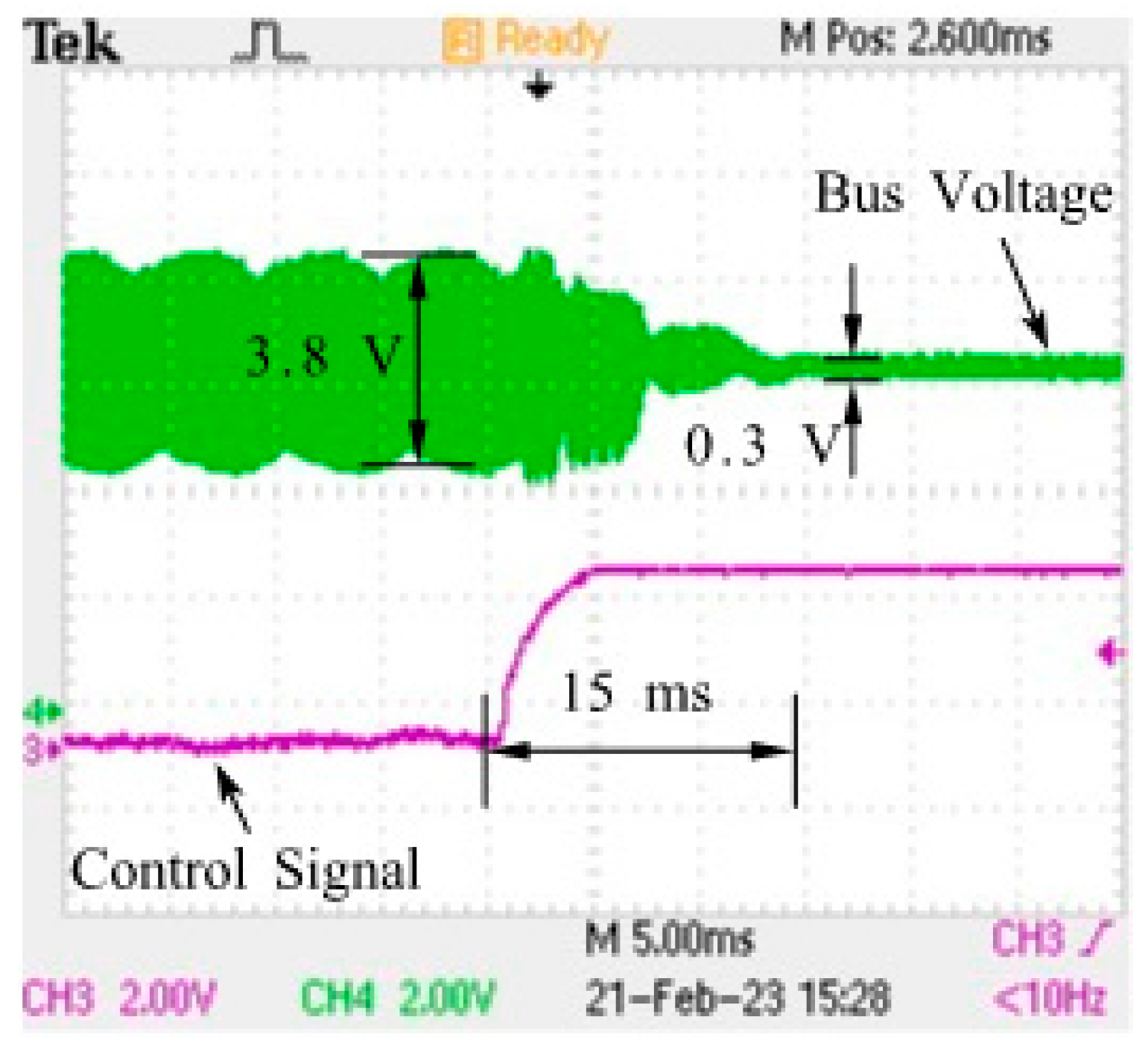
4.1. Startup of Phase-Shifting Control

In the initial state of the parallel system, three converters are operating. Before the phase-shifting control on signal arrives, each controller only performs voltage regulation and droop control. The initial phases of the converters are arbitrary. The dynamic of the bus voltage is shown in Figure 15. The ripple of the bus voltage is large before turning on the phase-shifting control. The ripple of bus voltage reduces from 3.8 V to 0.3 V in around 15 ms. To verify that switching interleaving is achieved in the steady state, the details of the converter current and bus voltage with different numbers of operating converters are shown in Figure 16. It can be seen from the figure that the phase differences between the converters are equal, and the current is balanced when two or more converters are operating. The voltage ripple of each converter is measured and shown in Table 3. The output ripple of each converter varies from 1.20 V to 1.50 V due to the manufacturing error of the power stage components. The bus voltage ripples with different numbers of interleaved converters are measured and shown in Table 3.
The experimental measurements are similar to the simulated results in Figure 8. The transient time is slightly longer than the simulated 10 ms, and the steady-state ripple is slightly larger than the simulation. The difference may result from the parameter errors of the converter components; this is reflected in the ripple of the single converter shown in Table 3.

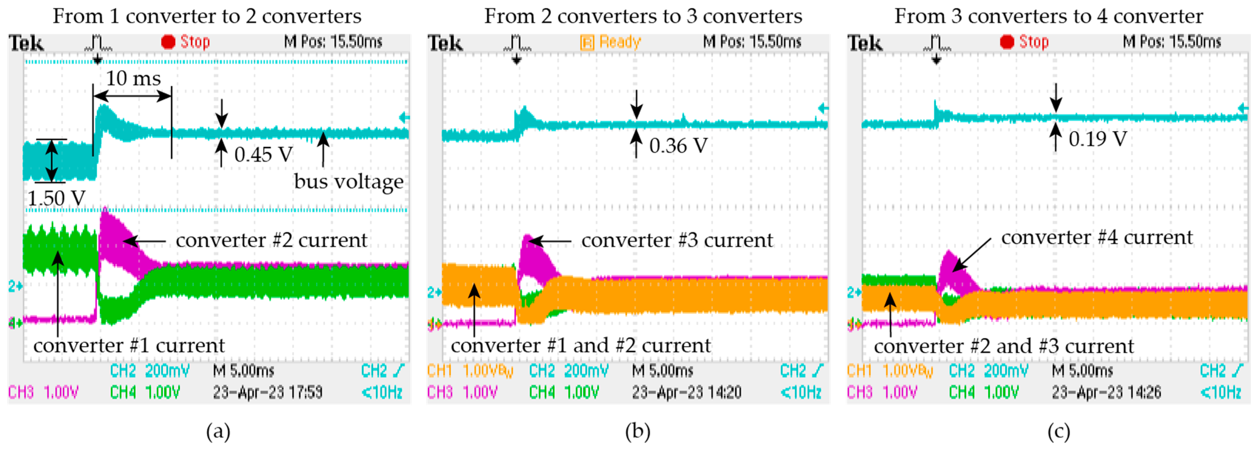
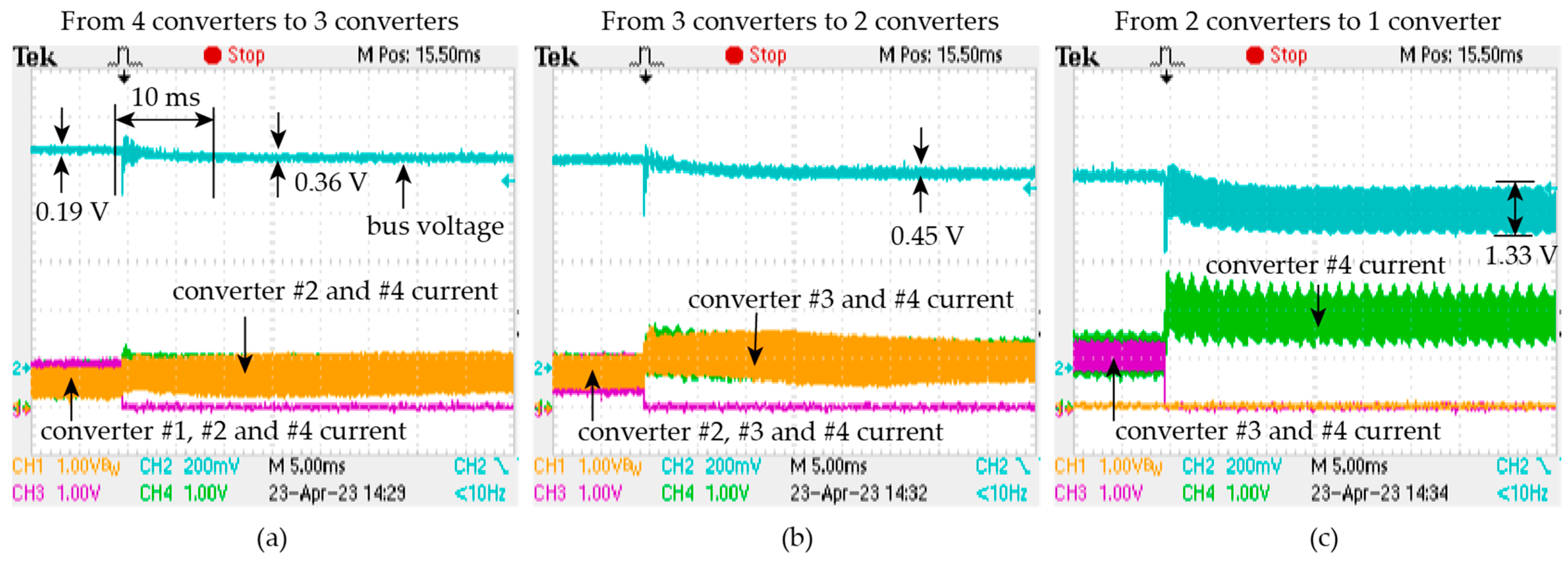
4.2. Unit Addition and Subtraction

To validate the plug-and-play feature of the proposed method, we performed measurements on the bus voltage and converter current when a converter was added to the bus and subtracted from the bus.
The result of the unit addition measurement is shown in Figure 17. The bus initially has one converter. The number of converters increases from one to four gradually. Figure 17a shows the transient of the insertion of converter #2. The bus voltage is significantly reduced from 1.50 V to 0.45 V, indicating that switching interleaving is achieved. The DC component of the bus voltage increases slightly, resulting from the droop control. The current of the two converters is almost equal, indicating that current sharing is achieved. The transients in (b) and (c) are similar to (a). Since the load remains constant in the process, the converter currents decrease and remain balanced every time a converter is inserted. The bus voltage ripple decreases every time a new converter is inserted. The transient times in (a), (b), and (c) are similar and are around 10 ms. In Figure 17c, four converters are operating after the insertion of converter #4, and four current waveforms should be shown. However, the converter #1 current is not included due to the channel limit of our oscilloscope. Figure 17 shows the transients of converter subtraction in which the number of converters is decreased gradually from 4 to 1. The measurements in Figure 18 also show that the switching interleaving can be recovered after a transient time of around 10 ms, and current sharing is maintained.
The results in Figure 17 and Figure 18 are mostly consistent with the simulated waveforms in Figure 9 and Figure 10. Several key indicators of the simulation and experiment are compared in Table 3. The transient times and waveforms of the simulation and experiment are similar. One major difference between the simulation and experiment is the bus ripple when three converters are operating. The simulation achieves a low bus ripple because three interleaved, identical converters with a conversion ratio of 1/3 can achieve zero ripple. In the experiment, there are differences between the converters, as reflected in the single converter ripple in Table 3. Therefore, the ripple of the three operating converters in the experiment is larger than the simulation. Another difference between the simulation and the experiment is that the ripple disturbance caused by the converter plugging and unplugging in the experiment is less than in the simulation. This may result from the different plugging schemes used in the simulation and the experiment. The simulation uses power line switches, whereas the experiment shuts down the MOSFET drivers.

4.3. Load Step

To validate the robustness of the control method with respect to load variation, we measured the bus voltage and converter currents when the load changed from 1 Ω to 2 Ω. The result is shown in Figure 19. The measured system has three converters connected.
The converters are interleaved before the load step, resulting in a small ripple of around 0.3 V. The ripple after the load step mostly remains unchanged, indicating that switching interleaving is maintained. The bus voltage and converter currents reach a steady state in around 15 ms, and the bus voltage slightly increased and the converter currents decreased because of the droop controller. The ripple before and after the load step is mostly the same and is aligned with Table 3, indicating that switching interleaving is maintained.

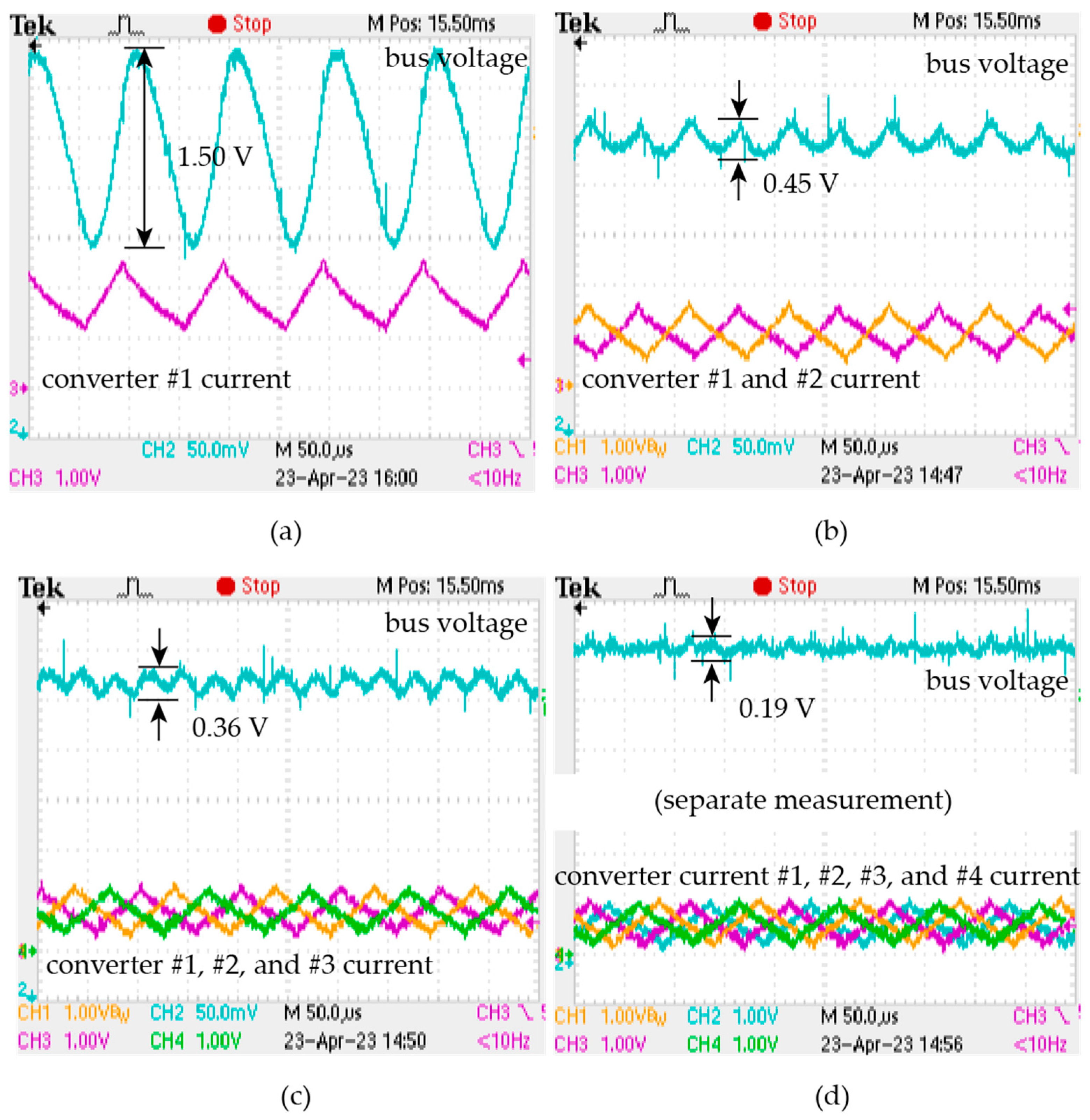
4.4. Summary and Discussion

The above measurements show that the proposed controller can achieve switching interleaving from an arbitrary initial state and can maintain the interleaving state with converter addition, converter subtraction, and load step. The simulation and experiment show similar waveforms in the above scenario. A comparison of several indicators from the simulation and experiment is listed in Table 3. There are differences in the experimental and simulation transient times and steady-state ripples. However, both the simulation and experiment achieve switching interleaving after an acceptable transient.
Compared with conventional communication-based methods, the main advantages of this method are the reduced cost of the communication modules, increased system complexity, and a more complete hot-plugging feature that eliminates the single point of failure of the parallel system. Some communication-based methods, such as those in [23,25,26], etc., achieve hot plugging by turning the power stage on or off. The communication module of the converter must remain operational at all times. If one communication module fails, the entire parallel system will fail as well.
The proposed method is compared with the two existing methods. Reference [29] uses a Lienard-type oscillator to generate PWM signals and achieve switching interleaving. To simulate the dynamics of the oscillator, the method in [29] requires a sample rate of 500   kHz (25 sampling points per switching cycle) and a controller time step of 150   ns . The proposed method only requires a sample rate of 40   kHz (four sampling points per switching cycle) and a controller time step of 200   μ s . The significant reductions in sampling rate and control frequency can reduce the controller performance requirement, resulting in lower costs. In addition, the number of parameters in the phase-shifting control method is reduced from four [29] to one, making it easier to implement the control method in converters of different topologies and switching frequencies. Reference [30] offers a gradient descent method to achieve switching interleaving. By using a simplified implementation, the method in [30] reduces the sampling rate to 10   kHz (one sampling point per switching cycle); however, precise sampling timing is required. To achieve precise sampling timing, the phase lag of the signal chain of each converter needs to be measured in advance. To sample signals at an arbitrary instant, the controller still needs to have sufficient clock frequency, which means that the cost of the controller may not be relieved. Compared with [30], the proposed method is insensitive to phase lag and does not require pre-measurement of the phase lag of the signal chain. In addition, both Refs. [29,30] are limited to canceling the first harmonic, whereas the proposed method can optionally cancel higher harmonics.

5. Conclusions

In this paper, we proposed a communication-free interleaving control method for parallel-connected converters. The proposed method uses FFT to extract the phase of the bus voltage ripple and adjust the phase of the converter current accordingly. Simulations and a system of four parallel-connected buck converters were built to validate the proposed method. Based on the simulation and experimental results, the main conclusions can be summarized as follows. The proposed method can significantly reduce bus ripple through switching interleaving. The proposed method supports the plug-and-play feature and achieves optimal phase shifting according to the number of operating converters. The proposed method does not influence current-sharing control. Current sharing and switching interleaving can be achieved simultaneously.
Compared with communication-based methods, the proposed method has the advantages of a lower cost and decreased system complexity because it does not require communication modules. The converters are only connected via the power lines, which allows for more flexibility when adding or subtracting converter units and also eliminates the single point of failure of the parallel system. The proposed method can be applied to many types of converters; however, it is limited to fixed-frequency converters and converters with a continuous current output. Future investigations could extend the control method to other converter topologies, including converters with discontinuous current output and bidirectional converters.

Author Contributions

Conceptualization, H.Y. and Q.F.; methodology, H.Y.; software, H.Y.; validation, Y.C.; writing—review and editing, B.W.; writing—review and editing, Y.S. All authors have read and agreed to the published version of the manuscript.

Funding

National Natural Science Foundation of China: 62203479; Industry-University-Research Project of Zhuhai: ZH22017001200053PWC; Guangdong Branch of National Engineering Research Center for Offshore Windpower: 2019B090904005.

Data Availability Statement

Not applicable.

Conflicts of Interest

The authors declare no conflict of interest.

References

  1. Poursafar, N.; Hossain, M.J.; Taghizadeh, S. Distributed DC-Bus Signaling Control of Photovoltaic Systems in Islanded DC Microgrid. CSEE J. Power Energy Syst. 2022, 8, 1741–1750. [Google Scholar]
  2. Du, W.; Ma, Z.; Wang, Y.; Wang, H.F. Harmonic oscillations in a grid-connected PV generation farm caused by increased number of parallel-connected PV generating units and damping control. CSEE J. Power Energy Syst. 2020. [Google Scholar] [CrossRef]
  3. ENajm, M.; Huang, A.Q. Integrated DC/DC parallel PnP PV architecture method for powering residential buildings. In Proceedings of the 2015 IEEE First International Conference on DC Microgrids (ICDCM), Atlanta, GA, USA, 7–10 June 2015; pp. 371–376. [Google Scholar]
  4. GCao; Guo, Z.; Wang, Y.; Sun, K.; Kim, H.-J. A DC-DC conversion system for high power HVDC-connected photovoltaic power system. In Proceedings of the 2017 20th International Conference on Electrical Machines and Systems (ICEMS), Sydney, NSW, Australia, 11–14 August 2017; pp. 1–6. [Google Scholar]
  5. Zhang, L.; Sun, K.; Xing, Y.; Feng, L.; Ge, H. A Modular Grid-Connected Photovoltaic Generation System Based on DC Bus. IEEE Trans. Power Electron. 2011, 26, 523–531. [Google Scholar] [CrossRef]
  6. Deng, F.; Chen, Z. Control of Improved Full-Bridge Three-Level DC/DC Converter for Wind Turbines in a DC Grid. IEEE Trans. Power Electron. 2013, 28, 314–324. [Google Scholar] [CrossRef]
  7. Chen, S.; Yang, Q.; Zhou, J.; Chen, X. A model predictive control method for hybrid energy storage systems. CSEE J. Power Energy Syst. 2020, 7, 329–338. [Google Scholar]
  8. Al-Ismail, F.S. DC Microgrid Planning, Operation, and Control: A Comprehensive Review. IEEE Access 2021, 9, 36154–36172. [Google Scholar] [CrossRef]
  9. Ghanbari, N.; Bhattacharya, S. Disturbance Rejection Analysis of a Droop-Controlled DC Microgrid Through a Novel Mathematical Modeling. IEEE J. Emerg. Sel. Top. Power Electron. 2022, 10, 1507–1518. [Google Scholar] [CrossRef]
  10. Pires, V.F.; Cordeiro, A.; Roncero-Clemente, C.; Rivera, S.; Dragicevic, T. DC–DC Converters for Bipolar Microgrid Voltage Balancing: A Comprehensive Review of Architectures and Topologies. IEEE J. Emerg. Sel. Top. Power Electron. 2023, 11, 981–998. [Google Scholar] [CrossRef]
  11. Shah, S.S.; Rastogi, S.K.; Bhattacharya, S. Paralleling of LLC Resonant Converters. IEEE Trans. Power Electron. 2021, 36, 6276–6287. [Google Scholar] [CrossRef]
  12. Drobnic, K.; Grandi, G.; Hammami, M.; Mandrioli, R.; Ricco, M.; Viatkin, A.; Vujacic, M. An Output Ripple-Free Fast Charger for Electric Vehicles Based on Grid-Tied Modular Three-Phase Interleaved Converters. IEEE Trans. Ind. Appl. 2019, 55, 6102–6114. [Google Scholar] [CrossRef]
  13. Sha, D.; Xu, G.; Xu, Y. Utility Direct Interfaced Charger/Discharger Employing Unified Voltage Balance Control for Cascaded H-Bridge Units and Decentralized Control for CF-DAB Modules. IEEE Trans. Ind. Electron. 2017, 64, 7831–7841. [Google Scholar] [CrossRef]
  14. Tarisciotti, L.; Costabeber, A.; Chen, L.; Walker, A.; Galea, M. Current-Fed Isolated DC/DC Converter for Future Aerospace Microgrids. IEEE Trans. Ind. Appl. 2019, 55, 2823–2832. [Google Scholar] [CrossRef]
  15. Magne, P.; Nahid-Mobarakeh, B.; Pierfederici, S. Active Stabilization of DC Microgrids Without Remote Sensors for More Electric Aircraft. IEEE Trans. Ind. Appl. 2013, 49, 2352–2360. [Google Scholar] [CrossRef]
  16. Xu, L.; Guerrero, J.M.; Lashab, A.; Wei, B.; Bazmohammadi, N.; Vasquez, J.C.; Abusorrah, A. A Review of DC Shipboard Microgrids—Part I: Power Architectures, Energy Storage, and Power Converters. IEEE Trans. Power Electron. 2022, 37, 5155–5172. [Google Scholar] [CrossRef]
  17. Ma, Y.; Corzine, K.; Maqsood, A.; Gao, F.; Wang, K. Stability Assessment of Droop Controlled Parallel Buck Converters in Zonal Ship DC Microgrid. In Proceedings of the 2019 IEEE Electric Ship Technologies Symposium (ESTS), Washington, DC, USA, 14–16 August 2019. [Google Scholar]
  18. Xie, P.; Guerrero, J.M.; Tan, S.; Bazmohammadi, N.; Vasquez, J.C.; Mehrzadi, M.; Al-Turki, Y. Optimization-Based Power and Energy Management System in Shipboard Microgrid: A Review. IEEE Syst. J. 2022, 16, 578–590. [Google Scholar] [CrossRef]
  19. Xu, L.; Guerrero, J.M.; Lashab, A.; Wei, B.; Bazmohammadi, N.; Vasquez, J.C.; Abusorrah, A. A Review of DC Shipboard Microgrids—Part II: Control Architectures, Stability Analysis, and Protection Schemes. IEEE Trans. Power Electron. 2022, 37, 4105–4120. [Google Scholar] [CrossRef]
  20. Su, M.; Liu, Z.; Sun, Y.; Han, H.; Hou, X. Stability Analysis and Stabilization Methods of DC Microgrid With Multiple Parallel-Connected DC–DC Converters Loaded by CPLs. IEEE Trans. Smart Grid 2018, 9, 132–142. [Google Scholar] [CrossRef]
  21. Kakigano, H.; Miura, Y.; Ise, T. Low-Voltage Bipolar-Type DC Microgrid for Super High Quality Distribution. IEEE Trans. Power Electron. 2010, 25, 3066–3075. [Google Scholar] [CrossRef]
  22. Zhang, X.; Huang, A.Q. A novel distributed control and its tolerance analysis for microprocessor power management. In Proceedings of the Twenty-First Annual IEEE Applied Power Electronics Conference and Exposition, 2006, APEC ‘06, Dallas, TX, USA, 19–23 March 2006; p. 7. [Google Scholar]
  23. Kudtongngam, J.; Sangkarak, K.; Lopattanakij, P.; Liutanakul, P.; Chunkag, V. Implementation of automatic interleaving and load current sharing techniques using single interleaving bus. IET Power Electron. 2016, 9, 1496–1504. [Google Scholar] [CrossRef]
  24. Gateau, G.; Cousineau, M.; Mannes-Hillesheim, M.; Dung, P.Q. Digital Decentralized Current Control for Parallel Multiphase Converter. In Proceedings of the 2019 IEEE International Conference on Industrial Technology (ICIT), Melbourne, Australia, 13–15 February 2019; pp. 1761–1766. [Google Scholar]
  25. Nguyen, P.C.; Phan, Q.D. The Development of Decentralized Space Vector PWM Method for Multilevel Multiphase Converters. In Proceedings of the 2020 IEEE Eighth International Conference on Communications and Electronics (ICCE), Phu Quoc Island, Vietnam, 13–15 January 2021; pp. 163–168. [Google Scholar]
  26. Luc-Andre, G.; Marc, C.; Isaac, S.; Philippe, L. Real-Time Simulation of Interleaved Converters with Decentralized Control. In Proceedings of the International Conference on Renewable Energies and Power Quality, Madrid, Spain, 4–6 May 2016. [Google Scholar]
  27. Cousineau, M.; Xiao, Z. Fully decentralized modular approach for parallel converter control. In Proceedings of the 2013 Twenty-Eighth Annual IEEE Applied Power Electronics Conference and Exposition (APEC), Long Beach, CA, USA, 17–21 March 2013; pp. 237–243. [Google Scholar]
  28. Phan, Q.D.; Gateau, G.; Nguyen, M.T.; Cousineau, M.; Ngoc, T.P.T. Decentralized Interleaving and Current Control for Multicellular Serial-Parallel Converters. In Proceedings of the 2019 International Symposium on Electrical and Electronics Engineering (ISEE), Ho Chi Minh City, Vietnam, 10–12 October 2019; pp. 1–6. [Google Scholar]
  29. Sinha, M.; Poon, J.; Johnson, B.B.; Rodriguez, M.; Dhople, S.V. Decentralized Interleaving of Parallel-connected Buck Converters. IEEE Trans. Power Electron. 2019, 34, 4993–5006. [Google Scholar] [CrossRef]
  30. Dutta, S.; Johnson, B. A Practical Digital Implementation of Completely Decentralized Ripple Minimization in Parallel-Connected DC–DC Converters. IEEE Trans. Power Electron. 2022, 37, 14422–14433. [Google Scholar] [CrossRef]
Figure 1. Diagram of the parallel system considered in this paper. The control schematic is also illustrated.
Electronics 12 02111 g001
Figure 2. Phasor decomposition of the first harmonic on the DC bus. Phasor I 1 represents the current harmonic of a particular converter. Phasor I 1 , o p t represents the optimal position of I 1 , where I 1 cancels the harmonics of other converters.
Electronics 12 02111 g002
Figure 3. Phasor diagrams and waveforms of a parallel system with three or four identical converters. In case II, the first harmonic is canceled, but the second harmonic is synchronized, resulting in a large second harmonic on the bus.
Electronics 12 02111 g003
Figure 4. Harmonic phasor diagram of a parallel system with N converters connected.
Electronics 12 02111 g004
Figure 5. Phasor simulation of three asymmetric converters. The left panel shows the first harmonic of the bus current and the phases of the converters. The tight panel shows the final phases of the converters at t = 60 ms.
Electronics 12 02111 g005
Figure 6. Phasor simulation of twenty asymmetric converters. The left panel shows the first harmonic of the bus current and the phases of the converters. The tight panel shows the final phases of the converters at t = 30 ms.
Electronics 12 02111 g006
Figure 7. Phasor simulation of converters addition and subtraction scenarios. Converter #1 is added at t = 0.6 ms, and converter #4 is removed at t = 1.2 ms. The left panel shows the first harmonic of the bus current and the phases of the converters. The tight panel shows the final phases of the converters at t = 1.6 ms.
Electronics 12 02111 g007
Figure 8. Waveforms of (a) bus voltage, (b) total current, (c) converter current, and (d) details of converter current during the start-up of the phase-shifting control.
Electronics 12 02111 g008
Figure 9. Waveforms of bus voltage, converter current, and details of converter current during the unit addition process. The number of operating converters increases from one to four gradually.
Electronics 12 02111 g009
Figure 10. Waveforms of bus voltage, converter current, and details of converter current during the unit subtraction process. The number of operating converters reduces from four to one gradually.
Electronics 12 02111 g010
Figure 11. Waveforms of bus voltage, converter current, and details of converter current before and after the load step.
Electronics 12 02111 g011
Figure 12. Waveforms of bus voltage and details of converter current with and without the higher harmonic controller.
Electronics 12 02111 g012
Figure 13. Diagram of the experimental prototype.
Electronics 12 02111 g013
Figure 14. Photo of the experimental prototype.
Electronics 12 02111 g014
Figure 15. Waveforms of bus voltage and phase-shifting control signal. Channel 4 is the bus voltage. Channel 3 is the phase-shifting control signal.
Electronics 12 02111 g015
Figure 16. Waveforms of bus voltage and converter currents at the steady state of (a) one converter, (b) two converters, (c) three converters, and (d) four converters. Due to the channel limit, voltage and current in (d) are measured separately.
Electronics 12 02111 g016
Figure 17. Waveforms of bus voltage and converter currents during unit addition transient. The number of converters gradually increases (a) from one to two, (b) from two to three, and (c) from three to four. The converter current of converter #1 is not included in (c) due to the channel limitation of the oscilloscope.
Electronics 12 02111 g017
Figure 18. Waveforms of bus voltage and converter currents during unit subtraction transient. The number of converters gradually decreases (a) from four to three, (b) from three to two, and (c) from two to one. The converter current of converter #3 is not included in (a) due to the channel limitation of the oscilloscope.
Electronics 12 02111 g018
Figure 19. Waveforms of bus voltage and converter currents when the load steps down.
Electronics 12 02111 g019
Table 1. Simulation parameters.
ParameterDescriptionValue
VinInput voltage24 V
VoutOutput voltage8 V
fswNominal switching frequency10 kHz
CfOutput capacitance23.5 μF
RloadLoad resistance1 Ω
LfBuck filter inductance200 μH
mDroop coefficient0.5 V/A
Simulation time step50 ns
Sample rate40 kHz
Table 2. Experimental prototype parameters.
ParameterDescriptionValue
VinInput voltage24 V
VoutOutput voltage8 V
fswNominal switching frequency10 kHz
CfOutput capacitance23.5 μF
RloadLoad resistance5 Ω
LfBuck filter inductance220 μH
GPhase-shifting gain1000 rad/(V·rad·s)
MDroop coefficient0.5 V/A
Controller time step100 μs
ADC sample rate40 kHz
DescriptionPart numberManufacturer
DSPTMS320F28335Texas Instr.
MOSFETNCE6005ASNCE
Gate driverTF2184-TAHTelefunken
Table 3. Comparison between simulation and experiment.
ScenarioIndicatorSimulationExperiment
StartupTransient time10 ms15 ms
Unit additionTransient time13 ms10 ms
Unit subtractionTransient time13 ms10 ms
Load stepTransient time10 ms15 ms
Single converterRipple (peak-to-peak)1.31 V1.50 V
1.21 V
1.20 V
1.33 V
2-parallelRipple (peak-to-peak)0.32 V0.45 V
3-parallelRipple (peak-to-peak)0.01 V0.30 V
4-parallelRipple (peak-to-peak)0.14 V0.25 V
Disclaimer/Publisher’s Note: The statements, opinions and data contained in all publications are solely those of the individual author(s) and contributor(s) and not of MDPI and/or the editor(s). MDPI and/or the editor(s) disclaim responsibility for any injury to people or property resulting from any ideas, methods, instructions or products referred to in the content.

