Abstract
With the optimization goal of improving the transmission efficiency of the magnetically coupled resonant wireless power transmission (MCR-WPT) system, the influencing factors and suppression methods of frequency splitting phenomenon (FSP) are analyzed from the perspective of input impedance based on the mutual inductance model. Then we propose the Monte Carlo-Interior Point method (MC-IPM) for nonlinear modeling to determine the optimal system parameters while ensuring that the system does not suffer from FSP. Finally, the simulation results show that the proposed method can obtain the optimal parameters faster and achieve higher transmission efficiency. The optimized system can meet the practical requirements and provides a reference value for improving the transmission performance of MCR-WPT.
1. Introduction
The increasing perfection of high degree of freedom wireless power transfer (WPT) technology means the advent of the era of contactless power transmission [1]. With advancement in electronic-based technologies, such as portable electronic devices, implanted medical devices, electric vehicles (EVs) and so forth, this seemingly magic way can change our traditional utilization patterns of the energy in various applications [2,3].
WPT can meet ever-growing demand for great convenience of being cordless and safe in wet and harsh environments compared with the traditional cable power transfer [4]. According to the distance from the source, it can be categorized into (a) far-field coupling (based on the electromagnetic radiation technique using the microwave, laser or solar satellite) and (b) near-field coupling (the magnetic field coupling includes magnetically coupled inductive (MCI) and magnetically coupled resonant (MCR)). When the transmission distance increases or the transmitting coil and the receiving coil are offset, transmission performance of MCI-WPT (efficiency, power and other performance metrics) will be decreased significantly, which greatly limits the application of the technology. The MCR-WPT technology can solve the problems above. In 2007, a 60 watt bulb was successfully lit up over a distance above 2 m with transmission efficiency of about 40% by scientists at MIT, and magnetically coupled resonant wireless power transfer (MCR-WPT) was first proposed [5]. In recent years, MCR-WPT has drawn significant interest for implementing the near-field WPT due to its high transfer efficiency as well as long transfer range. Researchers from all over the world have made in-depth study on MCR-WPT, and have achieved significant progress in charging safety, power level and transmission efficiency [6,7]. This technology can achieve high transmission efficiency when resonance occurs between the transmitter and the receiver. However, changes in the system itself and the external environment can cause the system to operate in a detuned state, and the transmission efficiency will drop sharply compared to that in a resonant state [8].
Therefore, the core of improving the transmission performance of the system is to ensure that the system works in a resonant state and avoid the frequency splitting phenomena (FSP) caused by overcoupling and achieve an increase in transmission efficiency. Li et al. [9] mechanically changes the angle of the coil and the transmission distance so that the system exits the overcoupling area, but the adjustment is not very accurate. Lyu et al. [10] uses two nonidentical resonant coils to avoid overcoupling between transmitter and receiver with close transfer distance. Tian et al. [11] proposed a double two-way spiral coil (DTSC) design method to narrow the overcoupling region of the system. In addition, impedance regulation circuits are also commonly used to improve WPT transmission performance [12,13,14,15]. Several methods described above change the external structure of the coil and circuit or move the mutual inductance distance to weaken the frequency splitting caused by overcoupling and achieve an increase in transmission efficiency. Since the external structure is not easily adjustable, some researchers have focused on the development of equivalent models of circuits and the derivation of mathematical expressions. They analyze in depth the internal connection of the parameters and their influence on the output. This leads to the selection of the optimal parameters and the optimization of the transmission performance. Li et al. [16] analyze the relationship between the transmission efficiency and the four system parameters, and thus give a method to optimize parameters of the system. Zhao et al. [17] derive the relationship equation between transmission efficiency and parameters, and introduce genetic algorithm to optimize the solution of transmission efficiency. Lu et al. [18] propose an improved genetic simulated annealing algorithm to solve the problem of parameter selection during the design of MCR-WPT. Yin et al. [19] analyze the factors affecting the transmission efficiency from the perspective of the system input impedance, and use the particle swarm optimization (PSO) algorithm to optimize the factors.
On the basis of the circuit parameter analysis above, the principle of FSP in WPT systems are analyzed from the perspective of input impedance, and a nonlinear modeling and parameter optimization method for MCR-WPT system based on Monte Carlo-Interior Point method (MC-IPM) are proposed. Firstly, this study selects the MCR-WPT system with series–series (S-S) type basic compensation circuit as the object of study and uses the theory of mutual inductance model to analyze the transmission characteristics of the system. Subsequently, the working principle of MCR-WPT is quantitatively analyzed and the factors affecting the transmission efficiency of the system are determined. Secondly, this study analyzes the mechanism of FSP in WPT systems from the perspective of input impedance, and provides the basis for quantitative calculation of system parameter optimization. Thirdly, with the goal of improving transmission efficiency, a nonlinear model based on MC-IPM was built, so as to optimize the relevant parameters affecting the transmission efficiency of the MCR-WPT system. Finally, a practical experimental platform is established to verify the effectiveness of the proposed method.
Combining the suppression of frequency splitting with the proposed method can ensure that the system achieves maximum transmission efficiency without a significant drop in output power due to FSP. The interior point method has less iteration variation, excellent convergence and fast computation speed. However the traditional interior point method requires strict initial value selection. Therefore, this study optimizes the initial values using the Monte Carlo method, which is able to avoid getting trapped in a local optimum. Experiment results show that the improved method can break the limitation of local optimal solutions. Compared with other intelligent optimization algorithms and parameter selection, the proposed method can obtain the optimal parameters faster and achieve higher transmission efficiency. The optimized system can meet the practical requirements and provides a reference value for improving the transmission performance of MCR-WPT.
2. Transmission Characteristics Analysis of MCR-WPT System
2.1. Factors Affecting System Transmission Efficiency
The S-S topology is used in magnetic coupling resonant WPT frequently, because its load receiving power and system transmission efficiency are better when the system is resonant [20,21]. A series–series(S-S) MCR-WPT system was selected as the object of study, and the theory of mutual inductance model was used to analyze the transmission characteristics of the system and determine the factors affecting the transmission efficiency of the system. Figure 1 demonstrates a typical S–S-type MCR-WPT system mutual sensing model topology [2].
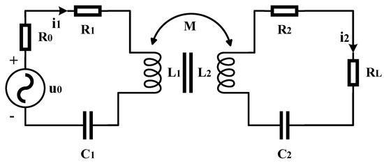
Figure 1.
Equivalent circuit model of MCR-WPT System.
Where, L1 refers to the transformer inductances on the primary side, while L2 indicates the one on the secondary side. Similarly, C1 and C2 refer to the primary and secondary compensation capacitors, respectively, which are used for enhancing energy transferred from an AC source to an output loading resistance RL. u0 indicates the high frequency AC voltage source and R0 is the internal resistance of the power source. R1 refers to the equivalent resistance of the primary coil, while R2 indicates the equivalent resistance of the secondary coil.
To simplify the analysis, this study makes the resonant compensation network structure symmetrical, so that the primary and secondary coils are identical (the mutual inductance of the two coils is equal, i.e., M12 = M21 = M). Since the system is powered by an adjustable power supply, the internal resistance R0 of the power supply is ignored.
The input power and output power of the system [22] can be respectively expressed as
where indicates the phase angle between the input voltage and the primary current. When the circuit is in resonance, .
The transmission efficiency of the system [22] is given by
Since the coil equivalent resistance is not easily changed after the coil winding is completed, its value is considered as a constant and is analyzed further. Therefore, the main factors affecting the transmission efficiency of the MCR-WPT system are the resonant frequency of the system ω, the mutual inductance of the coupling coil M and the load equivalent resistance RL.
2.2. Parameter Calculation of FSP Analysis
When the distance between the two coils is larger than a critical value or if the mutual inductance is too large, the characteristics of the transferred power will change from a single-peaked curve to a double-peaked curve [23,24]. The WPT system reaches its power peak when operating at non-resonant frequencies, and the power decreases at resonant frequencies instead. This is called the frequency splitting phenomenon (FSP), which seriously affects the system safety [25]. The mechanism of FSP generation will be analyzed from the perspective of input impedance and a basis for system parameter optimization is provided.
(a) Normally, the input impedance for WPT topology [26] can be given by
where indicates the equivalent impedance of the primary circuit, denotes the impedance of the secondary circuit equivalent to the primary and M is mutual inductance.
The real and imaginary parts of Equation (4) are separated by
(b) Because the system is symmetric, this study lets L1 = L2 = L and C1 = C2 = C, which leads to the derivation that = . Therefore, the mode of the imaginary part of the input impedance can be simplified as
where denotes the detuning factor and .
(c) When the circuit resonates, the imaginary part of the input impedance is zero and the input impedance of the circuit is equal to the resistance value of the resistor [27]. When the system undergoes FSP, the circuit resonance condition is met (the imaginary part of the input impedance is zero and the system output power reaches its maximum). However, the operating frequency does not coincide with the resonant frequency, and the output power drops at the resonant frequency. For the case that both FSP and circuit resonance may occur (), this study makes the imaginary part of the input impedance (Equation (6)) zero. The results of calculation can be expressed as
After transformation, Equation (8) can be expressed as
where , k denotes the coupling coefficient, .
According to the definition of M, the coefficient of on the left side of Equation (8) is less than zero, so the right side of the equation must also be less than zero. Similarly the left side of Equation (9) should be greater than 0. The three inequalities can be expressed as
where both Q1 and Q2 denote the quality factor, .
In summary, conditions that make Equations (8) and (9) have solutions that are given by
(d) Critical mutual inductance, load resistance and coupled coefficient are given by
Based on the analysis above, two conclusions can be drawn as follows: (i) When the load resistance is less than the critical load resistance and the mutual inductance M is greater than the critical mutual inductance , the system is in an overcoupled state and FSP occurs (both conditions of Equation (11) must be satisfied at the same time). (ii) On the contrary, when the load resistance is larger than the critical load resistance or the mutual inductance is smaller than the critical mutual inductance, the system will not experience FSP (only one of the two conditions must be satisfied).
To verify the correctness of theoretical analysis (i) and (ii), the system simulation parameters are assumed to be as shown in Table 1, where resonant capacitance is obtained by performing the calculation and . is calculated according to Equation (12).

Table 1.
Simulation parameters of the MCR-WPT system.
Figure 2 shows the different cases of FSP in the system with different load resistance values. When = 26 Ω, the critical coupling coefficient calculated according to Equation (12) is 0.15. Since the load resistance is less than the critical load resistance (= 195 Ω) and the system in the Figure 2a undergoes FSP when k is greater than 0.15, it is consistent with the analysis of conclusion (i). When = 195 Ω and 300 Ω, since the load resistance is already greater than the critical load resistance, the two conditions of Equation (12) cannot be satisfied simultaneously no matter what value of K is taken. In both cases, the systems in the Figure 2b,c do not undergo FSP, which is consistent with the analysis in conclusion (ii).
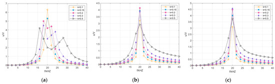
Figure 2.
FSP under different load resistance values: (a) RL = 26 Ω; (b) RL = 195 Ω; (c) RL = 300 Ω.
3. Transmission Efficiency Optimization of MCR-WPT System
3.1. Nonlinear Model Building and Simplification
This study chooses Monte Carlo simulation to optimize the initial values and couples the interior point method for nonlinear programming. Compared with the traditional nonlinear programming model, the proposed model can efficiently search for the global optimal solution with simple programming, fewer iterations and better convergence, while avoiding blind initial values and falling into local optima.
3.1.1. Nonlinear Interior Point Method
The interior point method is a common algorithm for solving linear programming or nonlinear optimization problems. The obstacle function method and the primal-dual method are the two classic interior point methods. The obstacle function method eliminates inequality constraints by adding obstacle terms to the objective function, and iteratively reduces the obstacle weights to continuously approach the optimal solution. With reference to the obstacle function method [28], a nonlinear interior point method applicable to MCR-WPT systems was proposed. The specific implementation process of the method is described as follows.
(a) Analyze the circuit mutual inductance model and establish the mathematical formulation for the nonlinear programming problems of MCR-WPT system, where the constraints include equation constraints and inequality constraints. General model for nonlinear programming is given by
where x denotes a point in an n-dimensional Euclidean space Rn (n-dimensional vector) and are real-valued functions defined on Rn.
(b) For the case containing an inequality constraint, consider adding a parameter vector to the optimization problem. The newly added parameter can be transformed to form an equation constraint to replace the previous inequality constraint.
(c) Unlike unconstrained optimization, the optimal value of constrained optimization is often on the constraint boundary. Therefore, the log function is introduced as a barrier function to ensure that the search is performed only within the bound of the inequality constraint. (Because the objective function will take a rapidly large value if the bound of the constraint is approached). With the inequality constraint removed from the objective function, the changed form can be expressed as
where indicates a quantity defined to check the distance between the current iteration point and the optimal point, parameters , (mentioned in (b)) and (limited by natural log) are all greater than zero. Thus, the constraint function CI (x) > 0.
During the iterative process of the interior point method, the value of μ also decreases until it converges to the point of true objective function minima. It is equivalent to simplifying a complex optimization problem with inequality constraints into a series of optimization problems without inequalities with different values of .
3.1.2. Monte Carlo Method
Monte Carlo method (MCM) is a numerical method based on probability and statistical theory, which can solve many non-deterministic problems in mathematical and physical phenomena [29]. The core idea of MCM is to represent the posterior distribution of the problem to be solved by a random sample of probability distribution and the corresponding probability. The mathematical description is as follows.
where x is a random variable, is the probability density function of x, indicates the mathematical expectation of x and denotes the expected estimate.
Taking N independent random samples from , the expected estimate of the MCM is expressed as the mean of the N sample values. By the law of large numbers, MCM converges to its expected value with probability 1 when N tends to infinity. is the exact mean of the random variable , but is only an unbiased estimate of . Therefore, the error of MCM needs to be calculated, and its expression is given by
where is the standard deviation of , which reflects the measure of the distribution of in the vicinity of . The relationship between and the standard deviation of can be expressed as
Equation (18) uses to estimate . The diffusion range of around is proportional to and inversely proportional to the square root of N. According to the central limit theorem, the set of a large number of random events converges to a normal distribution. Therefore, the error ε of MCM can be expressed as
where a is the confidence level.
3.2. Optimization Process of MCIPM
The idea of MC-IPM to optimize parameters of MCR-WPT system is described in Figure 3.
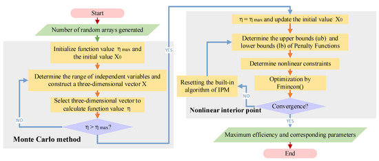
Figure 3.
Technical route flow chart of MC-IPM.
The interior point method is an effective method for solving nonlinear programming problems, but the solution result of a nonlinear programming algorithm is only a local optimal solution, and it has strict restrictions on the selection of initial values. If the global optimum is required, there are usually two ideas: (i) use the random number method to generate different initial values to optimize the code, and then find an optimal solution from them; (ii) first use Monte Carlo simulation to get a Monte Carlo solution, and then use this solution as the initial value to find the optimal solution. However, randomly selected initial values (method (i)) may lead to results that do not satisfy the constraints, or the algorithm cannot find a valid solution.
The Monte Carlo method can describe both the characteristics of things with random nature and physical experimental process more realistically, also can calculate multiple unknown quantities at the same time, and the program structure is simple and easy to implement. However, the Monte Carlo method is slow to converge and it is generally not easy to obtain approximation results with high accuracy. To solve the parameters optimization problems of systems with multiple constraints and parameters, the advantages of the two algorithms are combined.
3.3. Simulation Analysis
Based on the above analysis of FSP, ω, M and RL are selected as optimization variables to build a nonlinear model based on the MC-IPM method. The optimization objective here is to make the MCR-WPT system reach the maximum transmission efficiency without FSP, and the control variable method is used for experimental verification. The study of Section 2 provides a preliminary reference range for the MC-IPM nonlinear constraints and the determination of the upper and lower bounds of the three parameters (ω, M, RL) to be optimized. In this section, a parameter optimization study will be conducted based on the FSP simulation results in Section 2. According to Figure 2a, the range of FSP is 15 khz < f < 30 khz when 0.1 < k < 0.5, so the range of values of the variables to be optimized can be set as ω (2Π*15,000~2Π*30,000 rad/s), M (112~560 μH), RL (20~30 Ω), respectively. Table 2 shows the optimal parameters selected using the proposed method.
Table 2.
Results of parameter selection based on MC-IPM.
Figure 4 shows the variation in transmission efficiency with different parameter values. The parameters at the top of the surface function are similar to the selection results of MC-IPM, which proves that the method in this paper can effectively improve the system transmission efficiency by optimizing the parameter selection.
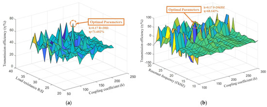
Figure 4.
Results of optimal parameter selection: (a) f0 = 20 kHZ; (b) RL = 30 Ω.
To further demonstrate the advantages of the proposed method, Figure 5 shows the results of transmission efficiency optimization using MC-IPM, Monte Carlo (MC), Sequential Quadratic Programming (MC-SQP), Active Set Method (MC-AS) and Adaptive Particle Swarm Algorithm (APSO), respectively.
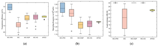
Figure 5.
Optimization results by different methods: (a) transmission efficiency; (b) operating frequency; (c) load resistance.
From Figure 5, it can be seen that the average value of transmission efficiency obtained using the method of MC-IPM is 75.86%, which is improved by 5.8%, 3.76%, 3.65% and 2.87% compared with other methods. Moreover, there are no outliers in the experiment, which indicates that the proposed method has higher robustness.
4. Experiments Analysis
In order to verify the effectiveness of the theory, the experimental platform was realized, which was composed of a signal generator, a homemade power amplifier, a homemade high-frequency inverter, a transmitting coil and a receiving coil with the same diameter and a electronic load meter, which are shown in Figure 6.
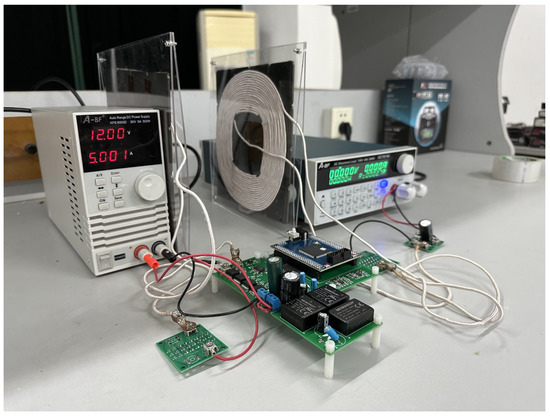
Figure 6.
Experimental platform.
Table 3 shows the device parameters used in the experimental platform. Based on the PSIM simulation results and the analysis above, RL = 2.4 Ω is chosen to calculate the critical mutual inductance . The range of values of the variables to be optimized were set as ω (2Π*15,000~2Π*25,000 rad/s), M (0.01~103 μH), RL (0.28~2.77 Ω), respectively.
Table 3.
Experimental parameters of the MCR-WPT system.
Table 4 shows the results of the optimal parameter selection based on MC-IPM and the parameters set for the practical experiment. The system resonance frequency of the experimental platform is 20 kHZ, and the actual input operating frequency is also set to 20 kHZ. The output is connected to the electronic load, and RL is set to 2.77 Ω due to the limitation of the instrument accuracy. The mutual inductance coefficient varies with the distance between the two coils, and this effect is very sensitive. The practical experiment may require complex adjustment to make the mutual inductance close to the theoretical value, but it is difficult to be identical, making the transmission efficiency slightly reduced. The test results of the experimental platform show that the actual transmission efficiency decreases by about 4%, which is due to the inherent device switching losses.
Table 4.
Simulation and practical experimental parameters.
The experimental results above prove the validity of the theoretical analysis, and the control variable method is used next to verify the superiority of the proposed method. Three sets of different resonant frequencies and load resistances are set, and the variation of η with k is tested under the three sets of experiment parameters, respectively. The actual experimental data are shown in Table 5. The critical coupling coefficients for the three sets are: (a) kcri = 0.172, (b) kcri = 0.123, (c) kcri = 0.086. Figure 7 shows the comparison curves of the three sets of experimental parameters. The reason that the independent variables of each curve do not take the same range of values is that the critical coupling coefficients are different for different parameter conditions. When the coupling coefficient of the system exceeds the critical value, frequency splitting will occur, which does not meet the optimization requirements of this paper. Therefore, only the data and curves that meet the requirements of FSP suppression are retained. The parameter combination of 20 kHZ, 2.77 Ω has an efficiency of more than 70% at k = 0.172, which is better than the highest efficiency under other parameter combinations and can achieve the goal of FSP suppression.
Table 5.
Experimental data by controlled variable method.
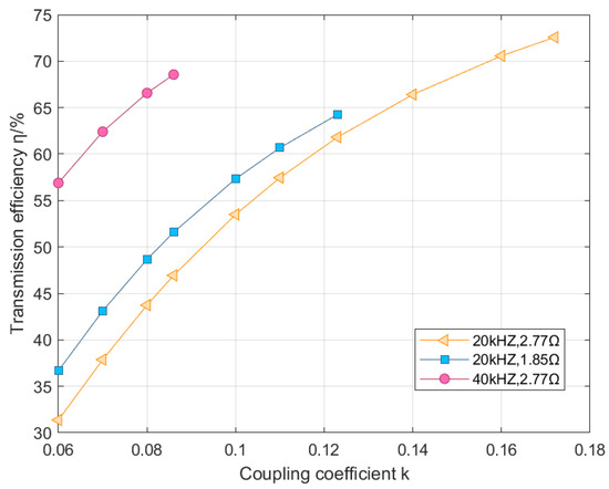
Figure 7.
Comparison of experimental results by controlled variable method.
In addition, the proposed method can also show good adaptability even in the case of FSP. The system in Table 6 undergoes FSP because the mutual inductance coefficient is greater than the critical mutual inductance, and the efficiency of the system decreases at the resonant state. However, the maximum efficiency of the system can still be greater than 70% regardless of whether the actual operating frequency is greater or less than the resonant frequency, which proves the correctness of the parameter selection.
Table 6.
Experimental parameters of the system when FSP occurs.
5. Conclusions
Firstly, the FSP is analyzed from the perspective of input impedance, and the influencing factors are determined as system operating frequency, coil mutual inductance and load resistance. Secondly, the analysis results above are combined with MC-IPM to optimize the system parameters so that the system can suppress the FSP while achieving the maximum transmission efficiency. Finally, the correctness and feasibility of the theoretical analysis are verified through simulation and practical experiments, which is a reference value for improving the transmission efficiency of MCR-WPT system. However, the mutual inductance measurement errors and device losses in the practical experiment result in a slight decrease in transmission efficiency.
Author Contributions
Conceptualization, Z.W. and Y.J.; methodology, Z.W.; software, Z.W.; formal analysis, Z.W.; investigation, G.X.; data curation, Y.W. and G.X.; writing—original draft preparation, Z.W.; writing—review and editing, Y.J.; supervision, Y.J.; and funding acquisition, X.S. All authors have read and agreed to the published version of the manuscript.
Funding
This research was funded by the National Student Innovation and Entrepreneurship Training Program Platform of the People’s Republic of China (Project No. 202210386001).
Data Availability Statement
Not applicable.
Conflicts of Interest
The authors declare no conflict of interest.
References
- Dou, R.; Zhang, X.; Li, Y.; Zhang, P.; Yang, Q. Review of Application Development and Research of Electromagnetic Shielding in Magnetic Coupling Resonant Wireless Power Transmission Syste. Proc. CSEE 2023, 1–22. Available online: http://kns.cnki.net/kcms/detail/11.2107.TM.20220916.1432.006.html (accessed on 1 March 2023).
- Mou, X.; DTGladwin Zhao, R.; Sun, H. Survey on magnetic resonant coupling wireless power transfer technology for electric vehicle charging. IET Power Electron. 2019, 12, 3005–3020. [Google Scholar] [CrossRef]
- Zhen, Z.; Pang, H.; Georgiadis, A.; Cecati, C. Wireless Power Transfer—An Overview. IEEE Trans. Ind. Electron. 2019, 66, 1044–1058. [Google Scholar] [CrossRef]
- Liu, F.; Yang, Y.; Ding, Z.; Chen, X.; Kennel, R.M. A Multifrequency Superposition Methodology to Achieve High Efficiency and Targeted Power Distribution for a Multiload MCR WPT System. IEEE Trans. Power Electron. 2018, 33, 9005–9016. [Google Scholar] [CrossRef]
- Kurs, A.; Karalis, A.; Moffatt, R.; Joannopoulos, J.D.; Fisher, P.; Soljacic, M. Wireless power transfer via strongly coupled magnetic resonances. Science 2007, 317, 83–86. [Google Scholar] [CrossRef] [PubMed]
- Fan, X.; Gao, L.; Mo, X.; Zhao, Q.; Jia, E. Overview of Research Status and Application of Wireless Power Transmission Technology. Trans. China Electrotech. Soc. 2019, 34, 1353–1380. [Google Scholar] [CrossRef]
- Liu, F.; Ding, Z.; Fu, X.; Kennel, R.M. Parametric Optimization of a Three-Phase MCR WPT System With Cylinder-Shaped Coils Oriented by Soft-Switching Range and Stable Output Power. IEEE Trans. Power Electron. 2020, 35, 1036–1044. [Google Scholar] [CrossRef]
- Zhang, X. Research Progress of Frequency Control Technology for Magnetically Coupled Wireless Power Transfer. Sci. Technol. Eng. 2022, 22, 3416–3424. [Google Scholar]
- Li, Y.; Yang, Q.; Yan, Z.; Zhang, C.; Chen, H.; Zhang, X. Analysis and Validation on Characteristic of Orientation in Wireless Power Transfer System via Coupled Magnetic Resonances. Trans. China Electrotech. Soc. 2014, 29, 197–203. [Google Scholar] [CrossRef]
- Lyu, Y.; Meng, F.; Yang, G.; Che, B.; Wu, Q.; Sun, L.; Erni, D.; Li, L.W. A Method of Using Nonidentical Resonant Coils for Frequency Splitting Elimination in Wireless Power Transfer. IEEE Trans. Power Electron. 2015, 30, 6097–6107. [Google Scholar] [CrossRef]
- Tian, Z.; Feng, L.; Gao, P.; He, F.; Lin, Y. Wireless power transmission based on the double two-way spiral coil. AIP Adv. 2019, 9, 015316. [Google Scholar] [CrossRef]
- Lu, K.; Huang, S.; Zhong, L. Frequency splitting suppression method for four-coil wireless power transfer system. IET Power Electron. 2016, 9, 2859–2864. [Google Scholar] [CrossRef]
- Wang, M.; Zhou, C.; Shi, Y.; Shen, M.; Feng, J. Development of a novel spindle-shaped coil-based wireless power transfer system for frequency splitting elimination. Int. J. Circuit Theory Appl. 2020, 48, 356–368. [Google Scholar] [CrossRef]
- Li, Y.; Dong, W.; Yang, Q.; Zhang, C.; Liu, L. Mechanism of Power Decreasing and Improvement Method for Wireless Power Transfer System in Over Coupled Regime. Trans. China Electrotech. Soc. 2018, 33, 8. [Google Scholar] [CrossRef]
- Beh, T.C.; Kato, M.; Imura, T.; Oh, S.; Hori, Y. Automated Impedance Matching System for Robust Wireless Power Transfer via Magnetic Resonance Coupling. IEEE Trans. Ind. Electron. 2013, 60, 3689–3698. [Google Scholar] [CrossRef]
- Li, C. Analysis on the Power and Efficiency of Magnetic Coupling Resonate Based on Wireless Power Transfer. Power Electron. 2014, 48, 28–31. [Google Scholar] [CrossRef]
- Zhao, Y. Research on efficiency optimization of magnetically coupled resonant wireless power transmission system. Transducer Microsystem. Technol. 2021, 40, 29–32. [Google Scholar] [CrossRef]
- Lu, S.; Zuo, C.; Piao, C. The Parameters Optimization of MCR-WPT System Based on the Improved Genetic Simulated Annealing Algorithm. Math. Probl. Eng. 2015, 22, 1–10. [Google Scholar] [CrossRef]
- Yin, H. Research on Transmission Characteristics of MCR-WPT System and Optimization of Transmission Efficiency. Power Electron. 2021, 10, 055. [Google Scholar]
- Woo, S. EMI Reduction Method for Over-Coupled WPT System using Series-None Topology. In Proceedings of the IEEE Wireless Power Transfer Conference (WPTC), San Diego, CA, USA, 1 June 2021; pp. 1–4. [Google Scholar] [CrossRef]
- Yao, Y.; Liu, X.; Wang, Y.; Xu, D. LC/CL compensation topology and efficiency-based optimization method for wireless power transfer. IET Power Electron. 2018, 11, 1029–1037. [Google Scholar] [CrossRef]
- Qi, P.; Xu, J.; Yi, F.; Zhang, Y.; Wang, P. The characteristic analysis of magnetically coupled resonant wireless power transmission based on SS compensation structure. In Proceedings of the 2017 First International Conference on Electronics Instrumentation & Information Systems (EIIS), Harbin, China, 3 June 2017; pp. 1–4. [Google Scholar] [CrossRef]
- Niu, W.; Chu, J.; Gu, W.; Shen, A. Exact Analysis of Frequency Splitting Phenomena of Contactless Power Transfer Systems. IEEE Trans. Circuits Syst. I Regul. Pap 2013, 60, 1670–1677. [Google Scholar] [CrossRef]
- Zhang, Y.; Zhao, Z.; Chen, K. Frequency-Splitting Analysis of Four-Coil Resonant Wireless Power Transfer. IEEE Trans. Ind. Appl. 2014, 50, 2436–2445. [Google Scholar] [CrossRef]
- Liu, X.; Yuan, X.; Xia, C.; Wu, X. Analysis and Utilization of the Frequency Splitting Phenomenon in Wireless Power Transfer Systems. IEEE Trans. Power Electron. 2021, 36, 3840–3851. [Google Scholar] [CrossRef]
- Liu, Y.; Fan, J.; Zuo, T.; Zhang, Y.; Liang, D.; Liu, J. Simulation study on series model of wireless power transfer via magnetic resonance coupling. In Proceedings of the 2017 IEEE 3rd Information Technology and Mechatronics Engineering Conference (ITOEC), Chongqing, China, 3–5 October 2017; pp. 191–195. [Google Scholar] [CrossRef]
- Zhao, H. Research on efficiency analysis and control strategy of inductively coupled wireless power transmission system. Electr. Energy Manag. Technol. 2017, 533, 6–11. [Google Scholar] [CrossRef]
- Wachter, A.; Biegler, L.T. On the implementation of an interior-point filter line-search algorithm for large-scale nonlinear programming. Math. Program. 2006, 1, 106. [Google Scholar] [CrossRef]
- Tang, L.; Zeng, C.; Miao, H.; Xu, W.; Zhang, Y.; Liu, Y. A novel maximum power point tracking scheme for PV systems under partially shaded conditions based on Monte Carlo Algorithm. Trans. China Electrotech. Soc. 2015, 30, 170–176. [Google Scholar] [CrossRef]
Disclaimer/Publisher’s Note: The statements, opinions and data contained in all publications are solely those of the individual author(s) and contributor(s) and not of MDPI and/or the editor(s). MDPI and/or the editor(s) disclaim responsibility for any injury to people or property resulting from any ideas, methods, instructions or products referred to in the content. |
© 2023 by the authors. Licensee MDPI, Basel, Switzerland. This article is an open access article distributed under the terms and conditions of the Creative Commons Attribution (CC BY) license (https://creativecommons.org/licenses/by/4.0/).