Abstract
This paper proposes an active resonant network based on variable resonant capacitances to improve the operating performance of the LCC-S compensated topology in the wireless power transfer (WPT) system for electric vehicles under coil-misaligned conditions. By adjusting the series and parallel compensation capacitances on the transmitting side, the output voltage can be kept constant and the energy transfer efficiency can be improved under different coil offsets. The switch-controlled capacitors (SCCs) are used to change the compensation capacitances continuously. To find the proper compensation capacitances to achieve the excellent performance of the system, the optimization algorithm is applied, and the corresponding digital control strategy is described to regulate the equivalent capacitances of SCCs. Experimental results with a 2.7 kW power scale show that the output voltage is constant, and the operating efficiency is always over 90% in the WPT system with an active resonant network under different misalignment conditions. In addition, the system is delivering an equal amount of energy for all misalignments within the range of 80 mm, which improves the expected value of transferred energy by about 29%.
1. Introduction
With the continuous depletion of global fossil energy and the deterioration of the ecological environment on our planet, it has gradually become a worldwide consensus to vigorously develop renewable energy and promote the electrification of transportation [1]. As a result, various types of electric vehicles (EVs), including automated guided vehicles (AGVs), are being adopted widely in freight and passenger transport applications to reduce global carbon emissions [1,2,3]. Wireless power transfer (WPT) is a novel charging method for EVs. Compared with the conventional wired power transmission, WPT has merits like no mechanical contact, spark-free, weatherproof, clean and tidy, etc. [4,5,6,7,8,9]. It is promising to be the most popular energy transmission mode in the near future.
Different from the traditional wired power transmission, the technical principle of the WPT is to transfer power based on the electromagnetic induction effect between two adjacent coils. Thus, the change of mutual inductance between coils will significantly affect the operational efficiency of the system. Generally, the energy transfer efficiency of the WPT is lower than that of the wired power transmission. Moreover, its efficiency will become even lower when mutual inductance between coils is reduced under misalignment conditions, which will cause energy waste and reduce the economic benefits of the power transmission system [10]. In addition to the efficiency, the output power of the WPT system will also suffer a large reduction under misalignment conditions [11].
To improve the output performance to reduce the energy consumption of the WPT system under misalignment conditions, many methods have been proposed, which can be roughly classified into three categories: (1) variable frequency control [12,13,14,15], (2) optimization on coupling coils [16,17,18,19,20,21,22,23], and (3) regulation on compensation parameters.
In [12,13,14,15], the switching frequency of the converter is adjusted to track the optimal system operating point to improve energy transfer efficiency. However, the variable frequency control puts forward relatively high requirements for the hardware condition and corresponding software design of the digital controller. The existence of the frequency bifurcation phenomenon (frequency splitting phenomenon) also limits the application range of the variable frequency control [14,15].
By optimizing the winding shape and dimension parameter of the coupling coils, or increasing the number of the adopted coils (such as the structure with multiple transmitting coils and only one receiving coil), the reduction of the mutual inductance of coils with the same offset distance can be decreased, so as to improve the system efficiency under misalignment conditions [16,17,18,19,20,21,22,23]. Whereas, the optimal coil design only can reduce the decrement of coil mutual inductance with the same offset, and cannot completely compensate for the negative effect of misalignment conditions on the system efficiency.
The compensation parameters of the resonant tank are quite important for the output performance of the WPT system. Without changing the switching frequency, by adjusting the compensation capacitances of the resonant network, the system impedance characteristics could be regulated to make the WPT system operate more efficiently. Capacitor arrays and relays are used in [24,25] to track the optimal operating point of the WPT system. The combination of serial and parallel capacitors is changing with different offset conditions. As the variation of the equivalent capacitance is discrete, the adjusting range of the capacitor arrays is limited.
To realize the dynamic adjustment on the impedance of the resonant network, switch-controlled capacitors (SCCs) are proposed and applied in WPT systems [26,27,28]. By controlling the digital pulse, the equivalent capacitance of an SCC can be regulated continuously within a certain range to control the system operating at an optimal status. With the adoption of the SCC topology to take the place of the series-connected compensation capacitor on the transmitting side, the stable output and soft-switching operation can be obtained to improve the energy transmission efficiency, when coupling coils are misaligned at different distances [26,27,28]. However, only the series-connected compensation capacitor is replaced by an SCC in the inductor–capacitor–capacitor (LCC) compensation topology adopted in [26,27,28]. There are also few studies on the effect of the variation of the parallel-connected compensation capacitance on the impedance characteristics of the resonant network.
As a result, a novel active resonant network design by replacing the series and parallel compensation capacitors on the transmitting side as two SCC topologies for the LCC-S compensated WPT system is proposed in this paper. By changing the series and parallel compensation capacitances, the system impedance is able to be modified to get system constant voltage (CV) output and optimal operating efficiency to transfer power when coils are misaligned. In the process of the determination of the optimal compensation capacitances, a comprehensive optimization method is used to find the globally optimal solution of the equivalent capacitances of SCCs.
The main contributions of this paper include:
- An active LCC-S-type resonant network design with dual-SCC topology is provided.
- The output performance characteristics of the LCC-S compensated resonant network with variable series and parallel compensation capacitances are analyzed.
- A comprehensive optimization algorithm is applied to optimize the regulation process of SCCs.
- The WPT system with the active compensation network is able to get the CV output and high operating efficiency when coils are misaligned in various directions.
The remainder of this paper is organized as follows. In Section 2, the circuit analysis of the active LCC-S compensated system based on dual-SCC topology has been conducted. Section 3 gives a detailed statement of the optimal parameter selection method based on an optimization algorithm, to improve the output stability and operating efficiency of the system. The experimental platform operating at a 2.7 kW power level is introduced in Section 4, and the following experimental results verify the availability of the proposed active regulating scheme. Section 5 summarizes the whole content.
2. Circuit Analysis of the Active LCC-S Compensated Network
LCC-S topology is widely adopted in stationary WPT systems due to its CV output, high design flexibility, and safety [29,30,31].
The circuit of the proposed active LCC-S compensated WPT system is shown in Figure 1. The converter on the transmitting side is made up of power switches (S1–S4 and D1–D4), and the rectifier is composed of Schottky diodes (D5–D8). Ls1 is the series-connected resonant compensation inductor on the primary side. Cs1 and Cp1 are the active series and parallel resonant compensated capacitors on the transmitting side, whose capacitances can be continuously varied. C2 is the series resonant compensation capacitor on the secondary side. L1 and L2 represent the transmitting coil and the receiving coil, individually. M means the mutual inductance between L1 and L2. Rs1, R1, and R2 are added as equivalent internal resistances to simplify the analysis of system power losses. Ro is the power load.
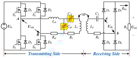
Figure 1.
The LCC-S compensated WPT system with the active resonant network.
2.1. Steady-State Analysis of the Active LCC-S Compensated Network
Due to the band-pass effect of the resonant tank, only the fundamental component of the square wave is considered in the theoretical analysis for simplicity [30]. The theoretical circuit based on the mutual inductance model of the active LCC-S compensated system can be depicted in Figure 2. RL represents the equivalent load resistance composed by the rectifier and Ro.
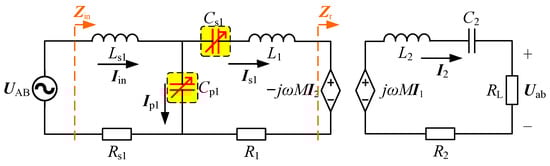
Figure 2.
Mutual inductance model-based circuit of the active LCC-S compensated network.
To help the reader understand, the meanings of some mathematical symbols used below are listed in Table 1.

Table 1.
Interpretations of Some Mathematical Symbols.
The classical resonant conditions of the traditional LCC-S compensated WPT system on the transmitting and receiving sides are expressed as (2) and (3), respectively. Where ω0 = 2πf0 indicates the resonant angular frequency, the subscript of “(o)” is used to refer that the capacitance for the fully tuned compensation condition.
Since the value of ω0 is unchanged in this paper, the secondary side circuit is always fully tuned, and it has [32]
In the active LCC-S topology, capacitances Cs1 and Cp1 will vary around Cs1(o) and Cp1(o), respectively, which can be expressed as
It can be deduced from (2)–(5) that the expressions of system input impedance and voltage gain can be given by
Based on that and KVL, the efficiency of the active LCC-S compensated WPT system can be expressed as
where the multinomials A and B can be expressed as
When α = β = 1.0, it means that the active LCC-S compensated WPT system works in the traditional tuned mode. Ignoring the equivalent resistances of Rs1, R1, and R2, for their fairly small impacts on the voltage gain, the expression of the voltage gain Gv(Tuned) can be simplified as
It is obvious that the voltage gain of the fully tuned LCC-S topology will be influenced by the mutual inductance M. Therefore, when the misalignment happened making M decrease, the output voltage of the conventional LCC-S compensated WPT system cannot be kept constant.
From [32], it is known that by changing the compensation capacitances Cs1 and Cp1 (namely, α and β), the reduced system output voltage gain could be compensated to its rated value Gv(Rated). However, the adoption of capacitor arrays only can change the equivalent capacitances discretely, making the adjustability limited, and it also makes the whole transmitter system bulky. To continuously adjust the values of Cs1 and Cp1, the switch-controlled capacitors (SCCs) are adopted in this paper.
2.2. The SCC Circuit
As Figure 3a shows, two SCC circuits are used to replace the traditional compensation capacitors in the proposed active resonant network, where “x” means “s1” or “p1”. The SCC circuit is composed of a capacitor paralleled with a branch of two anti-series-connected MOSFETs.
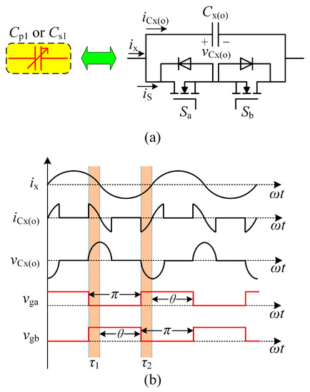
Figure 3.
Topology of SCC: (a) circuit and (b) operation waveforms [26].
Figure 3b shows the operation waveforms of the SCC. According to [26], driving signals vga and vgb for Sa and Sb could be set as complimentary pulses with 50% duty cycle and without dead time. It can be observed that vCx(o) keeps zero at turn-off points, so both Sa and Sb operate at ZVS condition, and their switching losses can be ignored. The equivalent capacitance of the SCC is related to θ, which means the phase-shift angle of the driving signal with respect to the corresponding branch current ix. The corresponding equivalent capacitance Cx(eq) of SCC can be expressed as [27]:
Based on (10) the ratio of Cx(eq)/Cx(o) versus control angle θ is illustrated in Figure 4. From it, we can know that Cx(eq) increases monotonically as θ is enlarged. When θ = π/2, Cx(eq) equals Cx(o), and as θ = π, Cx(eq) will be infinite. Such a wide variation range provides much freedom for the actual capacitance adjustment.
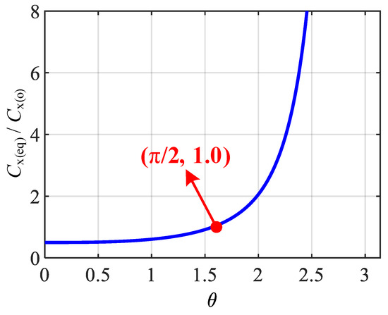
Figure 4.
Capacitance ratio Cx(eq)/Cx(o) versus control angle θ.
3. Control of the Active LCC-S Compensated Network
In [32], authors determine the values of α and β when the coupling situation changes according to two conditions: (1) Gv = Gv(Rated); (2) Soft-switching realizing condition. The experimental results have proved that the changed compensation capacitances can help the WPT system keep CV output and high efficiency when coil offset happens. However, whether the system gets its optimal efficiency or not under specific working conditions is unsure. To solve this problem, a different control strategy is utilized in this section.
3.1. Effects of α and β on System Output Voltage Gain and Efficiency
A simulation model is established in MATLAB to show the influence of α and β on the output characteristics directly. The parameters used in the simulation are listed in Table 2; k = M/(L1L2)−1 is the coupling coefficient. In this model, when coil structures are centrally aligned, the rated value of mutual inductance is M0 = 36 μH and Gv(Rated) = 1.0 simultaneously, and when the coupling condition changes, L1 and L2 are reckoned as unchanged, only M will be influenced.
Table 2.
Parameter Settings for Simulation Model.
Based on the simulation settings and (6)–(8), the different effects of α and β on Gv and η under different misalignment conditions (different M values) are shown in Figure 5, Figure 6, Figure 7 and Figure 8. The situation when M = 20 μH is used to simulate the coil misalignment condition. According to Figure 5 and Figure 6, there are different combinations of α and β that can make Gv get its rated value when M changes. However, the same combination of α and β also may cause a large loss in the system operating efficiency, as shown in Figure 7 and Figure 8. Besides, it can be seen from Figure 7 and Figure 8 that the system efficiency is very sensitive to the variation of α and β under misalignment conditions. A small change of α or β can cause a big drop in the operating efficiency. In order to maximize the efficiency of energy transmission in the practical operating condition, the optimal combination of α and β needs to be positioned precisely in advance, rather than dynamically adjusted by the classical PI control loop.
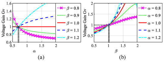
Figure 5.
When M = 36 μH, the voltage gain changes with (a) α and (b) β.
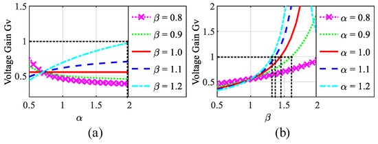
Figure 6.
When M = 20 μH, the voltage gain changes with (a) α and (b) β.
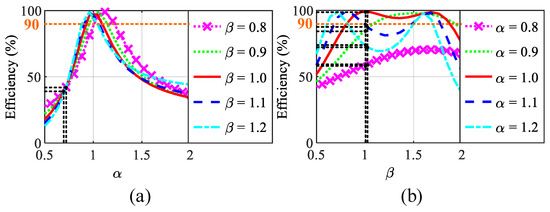
Figure 7.
When M = 36 μH, the efficiency changes with (a) α and (b) β.
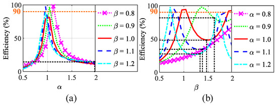
Figure 8.
When M = 20 μH, the efficiency changes with (a) α and (b) β.
It can be observed that both Gv and η are susceptible to the changes of α and β, and their influential relationship is nonlinear and hard to decouple. Thus, the control method adopted in this paper is to solve values of α and β by the optimization algorithm in advance and store them in the DSP program, then to directly invocation-corresponding parameters when the system coupling condition changes.
3.2. The Nondominated Sorting Genetic Algorithm II
Among various comprehensive optimization methods, the nondominated sorting genetic algorithm II (NSGA-II) is a relatively mature and widely used optimization algorithm to deal with multiobjective optimization problems [33,34]. In this paper, NSGA-II is utilized to determine the selection of nonlinear parameters (α and β).
For a typical minimization problem, Pareto dominance states that individual p dominates individual q if their objective functions satisfy the following [33]:
Fi(p) ≤ Fi(q) for all i’s;
Fi(p) < Fi(q) for at least one I;
where Fi represents the value of the ith objective function.
In each iteration, each individual in the population is sorted based on the Pareto dominance to ensure that excellent individuals could be selected.
Based on the aforementioned nondominant sorting principle, the basic procedure of NSGA-II can be illustrated in Figure 9.
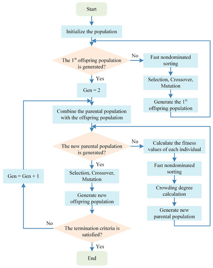
Figure 9.
Flowchart of NSGA-II.
- Step 1: Initialize the population and set the evolution counter Gen = 1.
- Step 2: If the first offspring population is generated, let Gen = 2. Otherwise, conduct nondominated sorting and selection, crossover, and mutation for the initial population to generate the first offspring population and make Gen = 2.
- Step 3: Combine the parental population with the offspring population to form a new population.
- Step 4: If a new parental population has been generated, go to Step 5. If not, the fitness values of the individuals in the new population should be calculated, and the operations such as fast nondominant sorting, calculation of crowding degree, and elite strategy are performed to generate a new parental population.
- Step 5: Conduct selection, crossover, and mutation for the generated parental population to generate the offspring population.
- Step 6: Check whether the termination criteria are satisfied. If not, make Gen = Gen + 1 and go back to Step 3. Otherwise, stop the algorithm loop.
3.3. Adoption of NSGA-II and Analysis for Calculation Results
In this paper, there are two optimization objectives:
- Keep the output voltage gain Gv constant when the coil’s coupling condition changes.
- Let the operating efficiency of the WPT system be as high as possible at the same time.
The two above optimization objectives need to be transformed into two minimization problems to be solved by the NSGA-II method. Define the system output voltage gain under the coil central aligned condition and coil offset condition as Gv(Rated) and Gv(Offset), respectively. Then, the first optimization objective can be changed to minimize δ = ||Gv(Offset)| − |Gv(Rated)|| to as close to zero as possible. In addition, the other optimization objective can be altered so as to minimize the value of |1 − η| to as small as possible.
Based on the transformed optimization objectives, the optimal combination of variables of α and β can be calculated through NSGA-II, by setting the population size and maximum iteration times to 80 and 300, respectively.
Taking the simulation model provided in Section 3.1 as an example, Pareto fronts of η versus δ when M = 20 μH are shown in Figure 10. It is reckoned that M = 20 μH represents that there is a relative displacement between the coils. In the classical WPT system design, α and β are both always equal to 1.
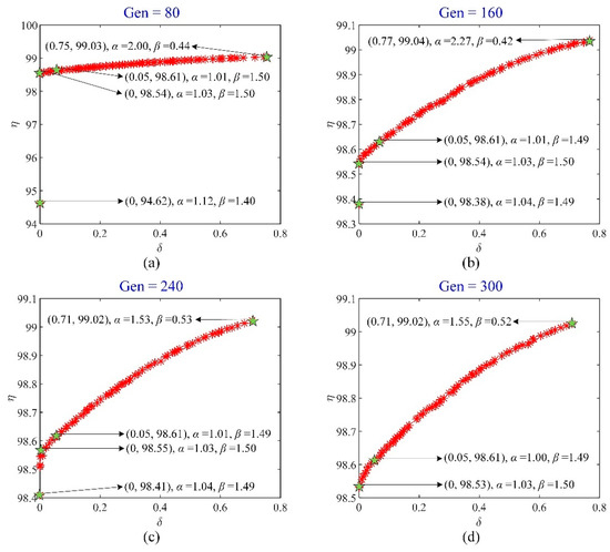
Figure 10.
Pareto fronts of η versus δ when M = 20 μH: (a) Gen = 80, (b) Gen = 160, (c) Gen = 240, (d) Gen = 300.
It can be seen from Figure 10 that the results of the optimization calculation gradually become stable with the increase of the generation of iterations. In the final calculation results, the maximum operating efficiency and the constant voltage gain of the active LCC-S compensated network cannot coexist. However, when |Gv(Rated)| is guaranteed, the reduction of η is within an acceptable range, and if the target value of |Gv| is not strictly equal to |Gv(Rated)| (namely, δ is not required to be zero strictly), the system efficiency can be improved further slightly. Here, the value of η only indicates the efficiency of the LCC-S resonant network, not including the converter and rectifier, and the losses caused by SCC topologies are neglected.
Based on the analysis above, the primary selection principle of the combination of α and β is to let δ be as close to zero as possible. Therefore, the optimal selection area is located on the left side of the Pareto fronts and near the longitudinal axis in Figure 10. Based on the optimal selection of α and β, resonant capacitances Cs1(o) and Cp1(o), and Equations (5) and (10), the corresponding control angles θs1 and θp1 of SCC-Cs1 and SCC-Cp1 could be calculated eventually, to realize the desired |Gv| and η.
Namely, it is possible to maintain the output voltage gain of the active LCC-S compensated network constant with relatively high operating efficiency by adjusting compensation capacitances on the transmitting side.
3.4. Control Strategy
Two processors are used in the control system design. The function of the processor on the transmitting side is to store the control angles of SCCs and generate the pulses to control the operation of the converter and SCC topologies, while the digital controller on the receiving side is used to record actual values of the system output voltage |VDo| and send them through WiFi communication to the primary side to evaluate the coupling condition of coils.
On the basis of the analysis above, the control scheme of the active LCC-S compensated WPT system adopting dual-SCC topology is proposed. The flowchart of the control logic is illustrated in Figure 11. The implementation process can be described as:
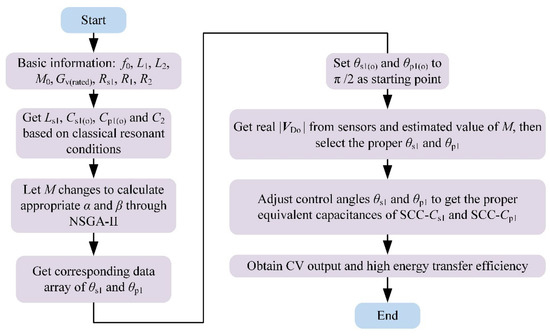
Figure 11.
The flowchart of the control logic.
- First, according to the application and actual working conditions of the WPT system, the design of its basic parameters is determined, including Ls1, L1, L2, Cs1(o), Cp1(o), C2, etc.
- Ls1, L1, L2, and C2 are considered as constant, then let the value of M vary in the range of 50% M0–100% M0 at intervals of 1 μH to calculate the optimal parameters α and β through NSGA-II, and the corresponding equivalent control angles θs1 and θp1 can be determined according to (5) and (10). The data of θs1 and θp1 are recorded as an array varying with M, and they are stored in the controller.
- In the practical operating process, the initial values of equivalent control angles θs1 and θp1 are both set as π/2, to make the equivalent capacitances of SCC-Cs1 and SCC-Cp1 be Cs1(o) and Cp1(o), individually. This means that the active WPT system is operating as the classical tuned system at first.
- When the output of the WPT system with initial parameters becomes stable, the actual output voltage |Uout| will be detected, and the actual voltage gain could be calculated by (11). As a result, the actual M can be estimated.
- 5.
- According to the estimated value of M, the values of θs1 and θp1 will be replaced. Therefore, the equivalent capacitances of SCC-Cs1 and SCC-Cp1 will be regulated to the proper values, to guarantee that the optimized CV output and the high-efficiency performance of the WPT system will be obtained.
Since the control angles of the proposed active resonant network are obtained from the NSGA-II in advance and adjusted by the table look-up scheme, there is no oscillation in the output voltage regulation process, but the system response speed is relatively slow, which is suitable for static WPT applications.
4. Discussion
4.1. Experimental Condition
Experiments with a 2.7 kW power level are conducted to evaluate the performance of the proposed active LCC-S compensated WPT system based on the utilization of two SCC topologies. Figure 12 shows the actual experimental setup, and the experimental settings are given in Table 3. The coupling coils are the symmetrical square-type, and the series compensated inductor Ls1 is wound with a magnetic core. The biggest difference between the proposed system compared with the traditional one is that the compensation capacitors on the transmitting side are replaced by two SCCs.
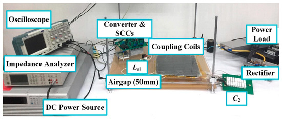
Figure 12.
Experimental setups of the WPT system.
Table 3.
Practical Experimental Conditions.
The side length of coupling coils is 180 mm. When coupling coils are misaligned in different directions, the values of Ls1, L1, and L2 are considered nearly constant, and only the values of M will be changed from 24.5 μH to 39.0 μH. Additionally, the minimum value of M is detected at the maximum misalignment distance in the horizontal direction with 80 mm.
4.2. Experimental Results
Based on the experimental settings, the corresponding output waveforms of the active LCC-S compensated WPT system under different working conditions are measured, and the output performance of the proposed system is compared with the classical one to demonstrate its superiority in Figure 13 and Figure 14.
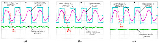
Figure 13.
Waveforms of the LCC-S compensated WPT system when: (a) M = 39.0 μH and without SCCs, (b) M = 24.5 μH and with SCCs, (c) M = 24.5 μH and without SCCs.
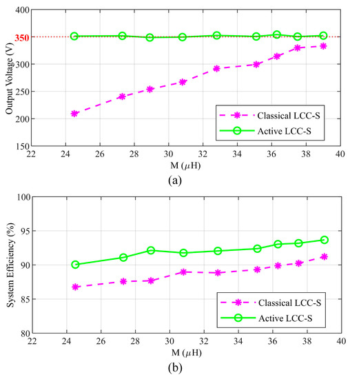
Figure 14.
Comparison between the classical and the active LCC-S compensated WPT system proposed in this paper on (a) output voltage and (b) efficiency.
It can be observed from Figure 13 that when the mutual inductance is reduced, the output energy will be decreased in the classical LCC-S compensated WPT system (without SCCs). However, with the adoption of topologies of SCC, the proposed active WPT system can keep the output stable, even under misalignment conditions, and the converter on the transmitting side is operating at ZVS condition, which can significantly reduce the switching power losses to improve the system efficiency.
The comparison of the output voltage and operating efficiency between the proposed and classical LCC-S compensated WPT systems under 2.7 kW power level (RL = 45 Ω) is shown in Figure 14. From Figure 14, it is obvious that, with the adoption of the dual-SCC topology, the CV output can always be maintained in the proposed active resonant network under various coil-coupling conditions. Besides, the proposed active compensated WPT system also has improved energy transfer efficiency under different misalignment conditions compared with the classical one. Considering the improvement in system efficiency within the whole offset range, the expected value of transferred energy of the WPT system is increased by about 29%.
In conclusion, the experimental results confirm the effectiveness of the proposed active compensation network design to improve the energy transfer efficiency and the CV output performance of the WPT system.
5. Conclusions
An active resonant network design scheme for the LCC-S compensated WPT system is proposed in this paper. By only dynamically changing the compensation capacitances on the primary side of the system, the CV output performance of the WPT system can be kept when the coupling coils are not centrally aligned. NSGA-II is used to obtain the optimal parameters to ensure that the WPT system has CV output and high-efficiency performance simultaneously. The SCC circuits are applied to regulate the corresponding capacitances to the desired values. The wireless communication combined with the table look-up method is used to regulate the performance of the SCC circuits to ensure that the output voltage is stable. Experiments are carried out to prove the validity of the proposed active resonant network design, with the mutual inductance varying from 39.0 μH to 24.5 μH. It is verified that the energy transfer efficiency is improved by 3.28% with the stable CV output under the worst misalignment condition.
Limited by the laboratory conditions, the active resonant network design has only been testified under a 2.7 kW power level, and in the future, the performance of this active resonant network can be studied and optimized in applications with higher power demands.
Author Contributions
Conceptualization, W.L. and L.D.; methodology, W.L., L.D., Z.D. and Z.J.; software, W.L. and Z.D.; validation, W.L., W.M., Z.D. and X.Q.; formal analysis, W.L., L.D., W.M., Z.D., X.Q. and Z.J.; investigation, W.L.; writing—original draft preparation, W.L.; writing—review and editing, L.D., Z.D. and Z.J.; supervision, L.D. All authors have read and agreed to the published version of the manuscript.
Funding
The APC was funded by Lijun Diao.
Data Availability Statement
Not applicable.
Conflicts of Interest
The authors declare no conflict of interest.
References
- Vu, V.-B.; Tran, D.-H.; Choi, W. Implementation of the Constant Current and Constant Voltage Charge of Inductive Power Transfer Systems with the Double-Sided LCC Compensation Topology for Electric Vehicle Battery Charge Applications. IEEE Trans. Power Electron. 2018, 33, 7398–7410. [Google Scholar] [CrossRef]
- Chen, Y.; Zhang, H.; Shin, C.-S.; Jo, C.-H.; Park, S.-J.; Kim, D.-H. An Efficiency Optimization-Based Asymmetric Tuning Method of Double-Sided LCC Compensated WPT System for Electric Vehicles. IEEE Trans. Power Electron. 2020, 35, 11475–11487. [Google Scholar] [CrossRef]
- Mai, R.; Luo, Y.; Yang, B.; Song, Y.; Liu, S.; He, Z. Decoupling Circuit for Automated Guided Vehicles IPT Charging Systems with Dual Receivers. IEEE Trans. Power Electron. 2020, 35, 6652–6657. [Google Scholar] [CrossRef]
- Fereshtian, A.; Ghalibafan, J.; Koohestani, M. A comprehensive design analysis of a cost-effective WPT system with a class-E power amplifier and a T-matching network. AEU Int. J. Electron. Commun. 2021, 137, 153826. [Google Scholar] [CrossRef]
- Atallah, H.A.; Huseein, R.; Abdel-Rahman, A.B. Novel and compact design of capacitively loaded C-shaped DGS resonators for dual band wireless power transfer (DB-WPT) systems. AEU Int. J. Electron. Commun. 2019, 100, 95–105. [Google Scholar] [CrossRef]
- Jeong, I.-S.; Lee, Y.-K.; Choi, H.-S. Characteristics analysis on a superconductor resonance coil WPT system according to cooling vessel materials in different distances. Phys. C Supercond. Its Appl. 2016, 530, 123–132. [Google Scholar] [CrossRef]
- Ji, L.; Wang, L.; Liao, C.; Li, S.; Ma, J. Research and design of automatic alternation between constant-current and constant-voltage modes on the secondary side in wireless charging systems. IET Electr. Power Appl. 2020, 14, 1119–1126. [Google Scholar] [CrossRef]
- Kumar, A.; Bertoluzzo, M.; Jha, R.K.; Sagar, A. Analysis of Losses in Two Different Control Approaches for S-S Wireless Power Transfer Systems for Electric Vehicle. Energies 2023, 16, 1795. [Google Scholar] [CrossRef]
- Jose, J.; Therattil, J.P. WPT compensation topology optimized for PV embedded electric vehicle. Sustain. Energy Technol. Assess. 2022, 53, 102605. [Google Scholar] [CrossRef]
- Ahmad, A.; Alam, M.S.; Rafat, Y.; Shariff, S. Designing and demonstration of misalignment reduction for wireless charging of autonomous electric vehicle. Etransportation 2020, 4, 100052. [Google Scholar] [CrossRef]
- Kalwar, K.A.; Aamir, M.; Mekhilef, S. A design method for developing a high misalignment tolerant wireless charging system for electric vehicles. Measurement 2018, 118, 237–245. [Google Scholar] [CrossRef]
- Martínez, A.; González, C.; Jaramillo, A.; Cárdenas, D.; Von Chong, A. Experimental data validating the optimization of a wireless power transfer prototype employing a novel phase shift measurement system and frequency control. Data Brief 2022, 45, 108675. [Google Scholar] [CrossRef]
- Xu, F.; Huang, H. Frequency selection for underwater wireless power transfer based on the analysis of eddy current loss. AEU Int. J. Electron. Commun. 2023, 163, 154618. [Google Scholar] [CrossRef]
- Schormans, M.; Valente, V.; Demosthenous, A. Frequency Splitting Analysis and Compensation Method for Inductive Wireless Powering of Implantable Biosensors. Sensors 2016, 16, 1229. [Google Scholar] [CrossRef] [PubMed]
- Yan, K.; Chen, Q.; Hou, J.; Ren, X.; Ruan, X. Self-Oscillating Contactless Resonant Converter with Phase Detection Contactless Current Transformer. IEEE Trans. Power Electron. 2014, 29, 4438–4449. [Google Scholar] [CrossRef]
- Zhang, Y.; Pan, W.; Wang, H.; Shen, Z.; Wu, Y.; Mao, X. Interoperability study of wireless charging system with unipolar and bipolar coils based on capacitor–inductor–capacitor–capacitor–series topology. Energy Rep. 2022, 8 (Suppl. S13), 405–411. [Google Scholar] [CrossRef]
- Chen, J.; Xu, J. A new coil structure for implantable wireless charging system. Biomed. Signal Process. Control. 2021, 68, 102693. [Google Scholar] [CrossRef]
- Yildiriz, E.; Kemer, S.B.; Bayraktar, M. IPT design with optimal use of spiral rectangular coils for wireless charging of e-tricycle scooters. Eng. Sci. Technol. Int. J. 2022, 33, 101082. [Google Scholar] [CrossRef]
- Domajnko, J.; Prosen, N. A Control of a z-Axis Rotation-Tolerant Wireless Power Transfer System Using a Double DD Coil. Electronics 2023, 12, 606. [Google Scholar] [CrossRef]
- Wen, H.; Li, J.; Zhang, K.; Ye, J.; Yan, Z.; Song, B.; Tong, X. Enhancing Power Transmission Stability of AUV’s Wireless Power Transfer System with Compact Planar Magnetic Coupler. J. Mar. Sci. Eng. 2023, 11, 566. [Google Scholar] [CrossRef]
- Li, W.; Chen, Y.; Peng, Z.; Wang, X.; Xia, C. Investigation on Induced Energy Extraction from High-Voltage Transmission Lines Based on Three-Coil WPT Systems. Energies 2023, 16, 3079. [Google Scholar] [CrossRef]
- Chen, J.; Li, R.; Yu, S.; Zhang, Z.; Cai, J.; Zhang, W.; Sun, H. Anti-Offset High-Voltage Wireless Power Transfer System Based on Many-to-One Topology. Electronics 2023, 12, 1898. [Google Scholar] [CrossRef]
- Wen, F.; Zhang, D.; Han, C.; Zhang, G.; Li, G.; Zhang, X.; Ma, J.; Yao, Z.; Yu, K. Anti-offset performance optimization of coupling coils in wireless power transfer system based on genetic algorithm. Energy Rep. 2022, 8 (Suppl. S10), 1–9. [Google Scholar] [CrossRef]
- Lim, Y.; Tang, H.; Lim, S.; Park, J. An Adaptive Impedance-Matching Network Based on a Novel Capacitor Matrix for Wireless Power Transfer. IEEE Trans. Power Electron. 2014, 29, 4403–4413. [Google Scholar] [CrossRef]
- Deng, J.; Mao, Q.; Wang, W.; Li, L.; Wang, Z.; Wang, S.; Guidi, G. Frequency and Parameter Combined Tuning Method of LCC–LCC Compensated Resonant Converter with Wide Coupling Variation for EV Wireless Charger. IEEE J. Emerg. Sel. Top. Power Electron. 2022, 10, 956–968. [Google Scholar] [CrossRef]
- Wang, X.; Xu, J.; Ma, H.; He, S. Inductive Power Transfer Systems with Digital Switch-Controlled Capacitor for Maximum Efficiency Point Tracking. IEEE Trans. Ind. Electron. 2021, 68, 9467–9480. [Google Scholar] [CrossRef]
- Wang, X.; Xu, J.; Leng, M.; Ma, H.; He, S. A Hybrid Control Strategy of LCC-S Compensated WPT System for Wide Output Voltage and ZVS Range with Minimized Reactive Current. IEEE Trans. Ind. Electron. 2021, 68, 7908–7920. [Google Scholar] [CrossRef]
- Li, W.; Wei, G.; Cui, C.; Zhang, X.; Zhang, Q. A Double-Side Self-Tuning LCC/S System Using a Variable Switched Capacitor Based on Parameter Recognition. IEEE Trans. Ind. Electron. 2021, 68, 3069–3078. [Google Scholar] [CrossRef]
- Zhang, W.; Mi, C.C. Compensation Topologies of High-Power Wireless Power Transfer Systems. IEEE Trans. Veh. Technol. 2016, 65, 4768–4778. [Google Scholar] [CrossRef]
- Takeda, K.; Koseki, T. Analytical investigation on asymmetric LCC compensation circuit for trade-off between high efficiency and power. In Proceedings of the International Power Electronics Conference (IPEC-Niigata 2018-ECCE Asia), Niigata, Japan, 20–24 May 2018; pp. 2309–2316. [Google Scholar]
- Tavakoli, R.; Pantic, Z. Analysis, Design, and Demonstration of a 25-kW Dynamic Wireless Charging System for Roadway Electric Vehicles. IEEE J. Emerg. Sel. Top. Power Electron. 2017, 6, 1378–1393. [Google Scholar] [CrossRef]
- Li, W.; Mei, W.; Yuan, Q.; Song, Y.; Dongye, Z.; Diao, L. Detuned Resonant Capacitors Selection for Improved Misalignment Tolerance of LCC-S Compensated Wireless Power Transfer System. IEEE Access 2022, 10, 49474–49484. [Google Scholar] [CrossRef]
- Luo, Z.; Wei, X.; Pearce, M.G.S.; Covic, G.A. Multiobjective Optimization of Inductive Power Transfer Double-D Pads for Electric Vehicles. IEEE Trans. Power Electron. 2021, 36, 5135–5146. [Google Scholar] [CrossRef]
- Deb, K.; Pratap, A.; Agarwal, S.; Meyarivan, T. A fast and elitist multiobjective genetic algorithm: NSGA-II. IEEE Trans. Evol. Comput. 2002, 6, 182–197. [Google Scholar] [CrossRef]
Disclaimer/Publisher’s Note: The statements, opinions and data contained in all publications are solely those of the individual author(s) and contributor(s) and not of MDPI and/or the editor(s). MDPI and/or the editor(s) disclaim responsibility for any injury to people or property resulting from any ideas, methods, instructions or products referred to in the content. |
© 2023 by the authors. Licensee MDPI, Basel, Switzerland. This article is an open access article distributed under the terms and conditions of the Creative Commons Attribution (CC BY) license (https://creativecommons.org/licenses/by/4.0/).