Communication

Terahertz Dual-Band Dual-Polarization 3-Bit Coding Metasurface for Multiple Vortex Beams Generation

1
Beijing Key Laboratory of Millimeter Wave and Terahertz Technology, School of Integrated Circuits and Electronics, Beijing Institute of Technology, Beijing 100081, China
2
State Key Laboratory of Precision Spectroscopy, Key Laboratory of Polar Materials and Devices, School of Physics and Electronic Sciences, East China Normal University, Shanghai 200241, China
*
Author to whom correspondence should be addressed.
Electronics 2023, 12(8), 1868; https://doi.org/10.3390/electronics12081868
Submission received: 13 March 2023 / Revised: 11 April 2023 / Accepted: 13 April 2023 / Published: 15 April 2023
(This article belongs to the Special Issue Recent Advances in Microwave and Terahertz Engineering)

Abstract

:
Terahertz technology and vortex beams have demonstrated powerful capabilities in enhancing the channel capacity of communication systems. This work proposes a design strategy of dual-band and dual-function 3-bit coding metasurface based on beam polarization characteristics. The unit cell of the metasurface is composed of two pattern structures, which has the ability to flexibly and independently control the reflection phases of incident plane wave at two frequency bands. The metasurface designed in this work is a combination of two patterns according to the addition operation and the convolution operation. The 3-bit coding metasurface generates two orbital angular momentum (OAM) beams with a deflection of 12.1° with modes l 1 = + 1 and l 2 = 1 under the y-polarized incidence at 0.6 THz. Similarly, the designed metasurface produces two OAM beams with a deflection of 16.5° under the incidence of x-polarized wave at 0.9 THz, and the modes are l 3 = + 1 and l 4 = 2 . The full-wave simulation results agree well with the theoretical predictions, which could prove the correctness and effectiveness of the proposed method. The metasurface designed according to this method has potential applications in multiple-input multiple-output (MIMO) communication systems.

1. Introduction

With the rapid development of modern wireless communication technologies, there is an increasing demand for the communication capacity and speed of the communication system. Terahertz technology, as one of the crucial technologies for 6G mobile communication, has abundant spectrum resources [1]. The advantages of terahertz waves include high transmission rate, high security, low scattering and high penetration, and thus they can be used to effectively improve the communication rate and capacity. With the commercialization of high-power femtosecond lasers and high-sensitivity detectors, the application of terahertz technology has attracted considerable attention, such as security detection [2,3,4], wireless communication [5,6], imaging [7,8,9] and biomedical [10].
As one of the basic properties of electromagnetic waves, orbital angular momentum (OAM) can provide a new degree of freedom for electromagnetic wave modulation and multiplexing, which is independent of amplitude, phase, polarization and other properties. The orientation angle factor of the vortex beam carrying orbital angular momentum is e j l φ , where φ is the azimuthal angle, and l is the modal order or topological charge of the corresponding OAM, which can theoretically be any integer [11]. The concept of Laguerre–Gaussian laser beam carrying OAM was firstly proposed by Allen in 1992 [12]. Since then, the research on OAM beams has received extensive attention, such as the measurement of the rotation of theblack hole [13], particle trapping and manipulating [14], defect detection in nano-structures [15], artificial spin ice systems [16], super-resolution imaging [17] and the ptychographic imaging of highly periodic structures [18], etc. In addition, generating multiple vortex beams with different OAM modes simultaneously in the communication system based on the orthogonality between different modes can effectively improve the channel capacity [19,20,21,22]. Therefore, it is of great interest to generate the vortex beams with multiple different OAM modes. In summary, in order to satisfy the increasing demand for wireless communication and channel capacity, the approach of combining OAM with terahertz technology provides a new idea to tackle the issue.
There are many traditional methods to generate OAM beams, such as spiral phase plates (SPP) [23,24], phased antenna arrays [25,26] and gratings [27,28].Compared with the above-mentioned conventional methods, metasurface offers another possibility because of the obvious advantages such as ultra-thin profile, light weight, easy fabrication and easy integration.Asartificial two-dimensional electromagnetic resonators, metasurfaces have attracted great attention and research because of flexible manipulationcapabilities ofelectromagnetic wavewith amplitude [29], phase [30] and polarization [31].Many fascinating phenomena based on metasurface have been demonstrated, such as anomalous refraction/reflection [32,33], optical focusing [34,35], spin Hall effect [36,37], invisibility [38,39] and holographic imaging [40,41].
Recently, terahertz OAM beam generation based on metasurface hasbeen proposed, including transmissive and reflective types [42,43,44]. The reflective metasurfaces are of interest due to the extremely high reflectance with a simple metal–insulator–metal (MIM) structure. A reflective metasurface is proposed in [45] to generate an OAM vortex wave beam with different topological charges in different terahertz regions. However, this paper only investigates vortex waves with a single deflection angle under circular polarized waves incidence. The silicon-based multi-bit coding metasurface proposed in [46] is limited to one frequency band, although it can generate multiple vortex beams. A dual-band terahertz reflective metasurface generating vortex beams reflected along the normal direction of metasurface carrying different OAM modes at 0.45 and 0.7 THz was proposed in reference [47]. Reference [48] proposed a single-layer metasurface based on Pancharatnam–Berry phase unit cells which can generate two anomalous reflected vortex single-beams with topological charge of +1 and +2 at 5.2 and 10.5 GHz, respectively. In addition, a metasurface multiple vortex beams generator based on vanadium dioxide can achieve flexibly control of transition state with the change of temperature at two different frequencies, while it suffers from low transition efficiency [49]. Recently, reference [50] proposed a reflective metasurface with high efficiency to generate multiple vortex beams at 0.38 and 1.14 THz, while the OAM mode of vortex beam is single at each band. Although several dual-band metasurface-based vortex beam generators have been proposed, very few dual-band multiple vortex beams metasurface generators with high efficiency have been reported in the terahertz band, where the OAM mode and deflection angle of each beam can be designed independently.
In this work, we have proposed a novel structure for designing dual-band metasurface-based vortex beam generators with multiple beam directions and OAM modes in the terahertz band. The unit cell of the metasurface consists of a combination of two separate patterns that respond to different frequency bands without interfering with each other. Two 3-bit coding reflection metasurfaces consisting of 32 × 32 unit cells are proposed, according to addition operation [51] and convolution operation [52]. Dual-band dual-polarization single vortex beam metasurfaces can generate two single vortex beams with different deflection angles under the illumination of orthogonal linear polarizations at 0.6 and 0.9 THz. Furthermore, a dual-band dual-polarization multiple vortex beams metasurface is proposed which can generate multiple vortex beams with different modes and different deflection angles under the illumination of orthogonal linear polarizations at 0.6 and 0.9 THz. The proposed method is verified by the full-wave simulation and theoretical prediction. This work provides an effective means for formation of multiple beams and multi-functional terahertz control device.

2. Design of Metasurface 3-Bit Unit Cell

Figure 1a shows the schematic of the metasurface OAM generator. It can be seen from Figure 1a that the metasurface generates dual vortex beams with different angular deflection at two frequency bands under the orthogonal linearly polarized incidences. Figure 1b illustrates the three-dimensional structure of the unit cell. The unit cell consists of a top patterned metallic layer and a ground plane separated by a polyimide polymer substrate ( ε r = 3.0 and tan δ = 0.03 ) [53] with the thickness h of 35 μm, and the lattice length of unit cell p is 150 μm. The unit cell is a combination of Pattern Iand Pattern IIas shown in Figure 1c,d, respectively. According to the electromagnetic field theory, wavelength is inversely proportional to frequency. The length of Pattern I is generally set longer than that of Pattern II, which means that the working frequency corresponding to Pattern I is lower than that of Pattern II. By adjusting the length carefully, we set working frequencies of Pattern I and Pattern II at 0.6 and 0.9 THz, respectively. Because 0.6 and 0.9 THz are located in the terahertz transmission windows [54], they are suitable for applications such as terahertz communication, detection and radar, etc.
Here, eight different structures are designed for Pattern I and Pattern II, respectively, corresponding to eight different reflection phases at two frequency bands. Here, the eight structures of Pattern I are marked as “*/1”, “*/2”, “*/3”, “*/4”, “*/5”, “*/6”, “*/7”, “*/8”, and the eight structures of Pattern II are marked as “1/*”, “2/*”, “3/*”, “4/*”, “5/*”, “6/*”, “7/*”, “8/*”. The 3-bit unit cells designed with the 2patterns are constructed by a sequence of eight coding elements “000”, “001”, “010”, “011”, “011”, “100”, “101”, “110” and “111”, exhibiting 0°, 45°, 90°, 135°, 180°, 215°, 270° and 315° phase responses, as shown in Table 1 and Table 2, respectively. The unit cell encoded by the two patterns also corresponds to the metasurface coding theory, which could greatly simplify the design and optimization procedures. In addition, the metasurface with the 3-bit coding phase distribution could provide almost the same performance for the wavefront manipulations compared to that with the precise phase distribution. The 64 unit cells can be obtained by arbitrarily combining the above two patterns with different structure parameters.The changeable structural parameters l 1 , l 3 , l 4 and l 6 are also listed in Table 1 and Table 2, while the remaining parameters are fixed as l 2 = 20 μm, l 5 = 20 μm, w = 7 μm, s 1 = 7.5 μm and s 2 = 10 μm. It is worth mentioning that the two patterns would not overlap each other. The simulation of the unit cell structure is performed in the CST Studio Suite 2020 with the boundary conditions set to “unit cell” in the x and y directions, and the incident waves are x-polarized and y-polarized plane waves along the −z direction.
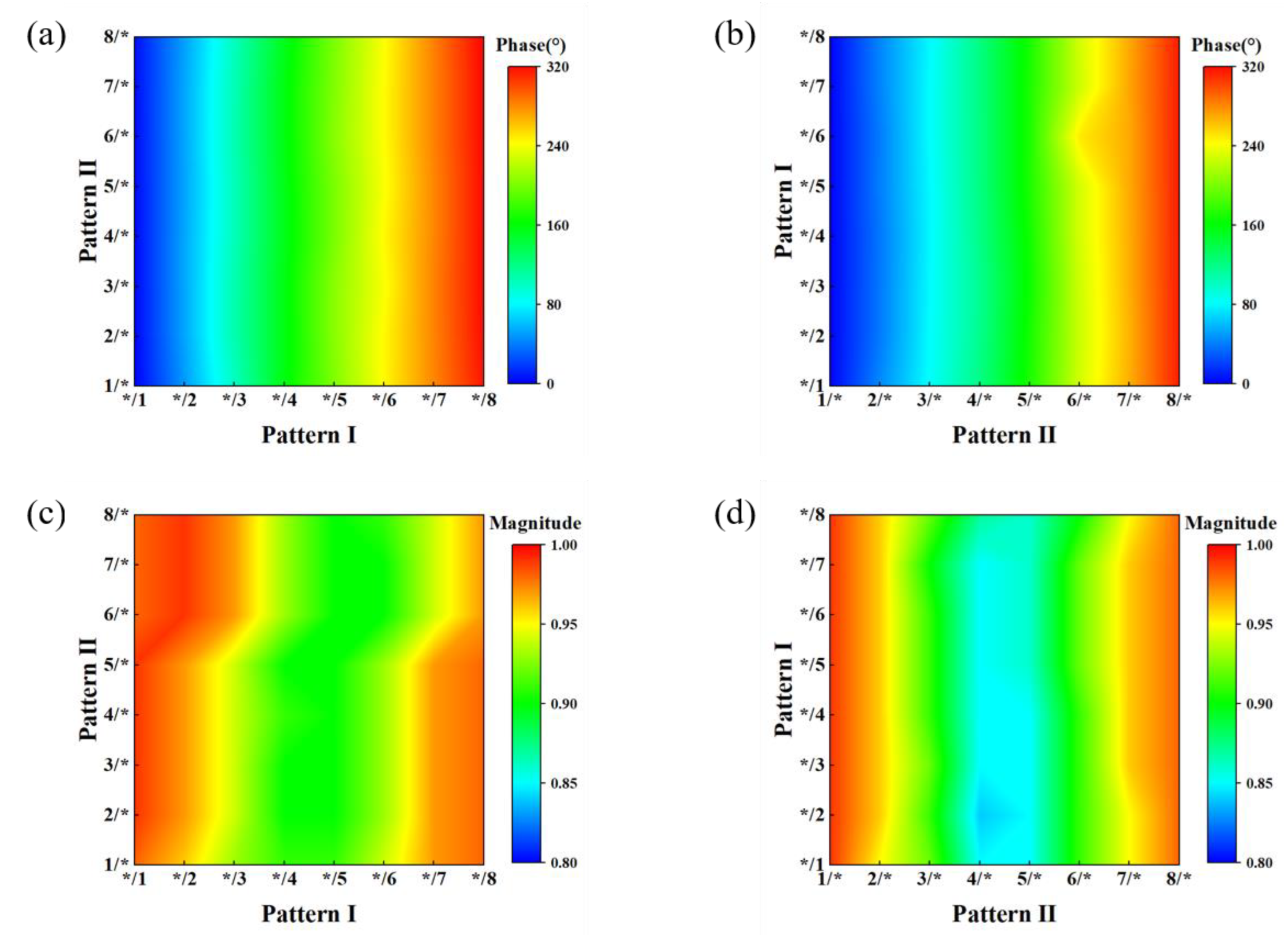
Figure 2 shows the reflection phase and amplitude diagrams of the unit cell. Figure 2a,b displays the phase response curves of 64 unit cells under the y-polarized incidence at 0.6 THz (under the x-polarized incidence at 0.9 THz). The phase responses of all eight structures of Pattern I and Pattern IIcan cover 360°. Moreover, the reflection phase under the y-polarized plane wave incidence at 0.6 THz dominated by Pattern I remains almost unchanged when the structure parameters of Pattern II are changed. Similarly, the reflection phase under x-polarized plane wave incidence at 0.9 THz dominated by Pattern II remains almost unchanged when the structure parameters of Pattern I are changed. In summary, the coupling between the two patterns can be ignored. In addition, Figure 2c,d plot the reflection amplitude distributions under different incidences. As shown in Figure 2c,d, the reflection amplitudes of the proposed metasurface unit cell are higher than 0.9 and 0.85 at 0.6 and 0.9 THz, respectively. The loss of the proposed unit cell mainly includes the dielectric loss and metal loss.

3. Dual-Band Dual-Polarization Single Vortex Beam Metasurface

The scattering far-field of the metasurface with M × N unit cells in the xoy plane under the normal incidence of plane can be expressed as
f ( θ , φ ) = f m , n ( θ , φ ) A F ( θ , φ )
where f m , n ( θ , φ ) is the radiation intensity ofeach metasurface unit cell and A F ( θ , φ ) is the array factor of metasurface.
The array factor of metasurface could be derived according to antenna far-field radiation theory:
A F ( θ , φ ) = m = 1 M n = 1 N exp { j ψ ( m , n ) + k p sin θ × [ ( m 1 / 2 ) cos φ + ( n 1 / 2 ) sin φ ] }
where ψ ( m , n ) is the reflection phase of each metasurface unit cell; k is the wave number ( k = 2 π λ , λ is the working wavelength); p is the lattice length of unit cell; θ is the elevation angle; and φ is the azimuth angle.
According to Equation (2), the regulation of metasurface phase distribution is the key to realize the manipulation of wavefront.
The theoretical phase distribution for producing the vortex beam at each point (x, y) on the metasurface can be calculated as
φ ( x , y ) = l arctan ( y x )
where l is the number of vortex beam mode, which can theoretically be any integer.
The reflected beam upon the gradient-phase metasurface deviating from the direction of specular reflection is referred to as anomalous reflection and satisfies the generalized Snell’s reflection law [55]:
n r sin θ r n i sin θ i = λ 0 2 π d φ d x
where n i , n r , θ i , θ r , λ 0 and d φ / d x represent the refractive index of the incident medium, the refractive index of reflective medium, incidence angle, reflection angle, working wavelength and phase gradient along the interface, respectively.
In this work, the metasurface is put in vacuum (i.e., n t = n i = 1 ), so Equation (4) can be simplified as
sin θ r sin θ i = λ 0 2 π d φ d x
The generalized Snell’s reflection formula can be further simplified if the gradient-phase metasurfaces are arranged in an equiperiodic form. The angle of the reflected beam can be calculated by the following equation:
θ r = arcsin ( λ 0 L )
where L = np is period length with p as the lattice length of unit cell; n is the number of unit cells in a period.
Figure 3 shows the phase distribution of the single vortex beam metasurface consisting of 32 × 32 unit cells. In this part, we designed the gradient phase distribution of M2 and M5 in Figure 3a,b with n = 16 along x-axis and n = 4 along y-axis. θx and θy are calculated as 12.4° and 16.7° according to Equation (6), representing the theoretical deflection angles along the x-axis and y-axis of the reflected wave beams, respectively. M1 and M4 are the phase distribution of the vortex wave with l = + 1 according to Equation (1). The M3 and M6 obtained by the convolution operation (i.e., direct summation of phases) correspond to the phase distribution of Pattern I and Pattern II, respectively.A 3-bit bifunctional single vortex beam metasurfaceis created by combining the structures of Pattern I and Pattern II, which can produce a single vortex beam with l = + 1 deflected by 12.4° along y-axis at 0.6 THz under the y-polarized incidence and another single vortex beam with l = + 1 deflected by 16.7° along x-axis at 0.9 THz under the x-polarized incidence theoretically.
In order to ensure the simulation accuracy, we set 15 mesh cells per wavelength and perform local mesh refinement for the tiny structure. In addition, we take advantage of the GPU hardware acceleration to ensure the efficiency of the simulation with massive meshes.
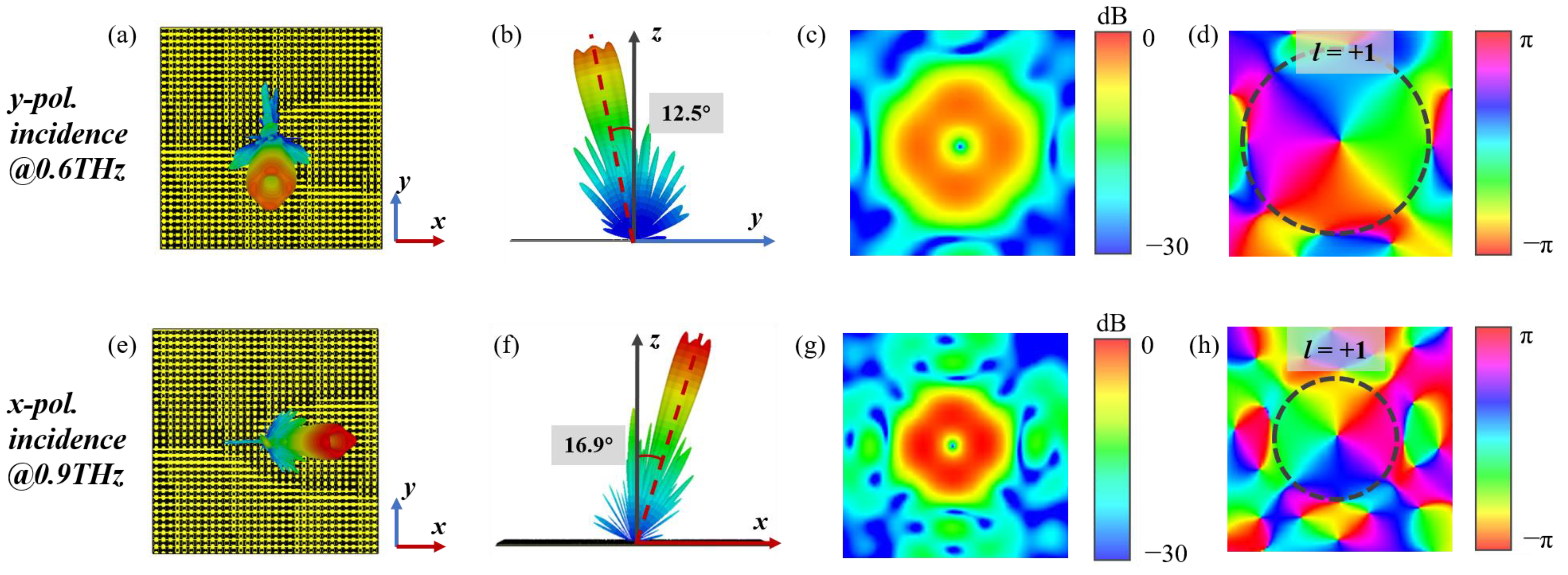
Figure 4 presents full-wave simulated scattering field diagrams of the 3-bit coding single vortex beam metasurface. The top and side views of the 3D far-field scattering diagrams at 0.6 THz under the y-polarized incidence are depicted in Figure 4b, respectively. It can be seen from these two figures that the beam deflection along the y-axis is almost the same as expected. Moreover, the 2D far-field diagrams of the amplitude and phase are shown in Figure 4c,d, respectively. From the ring intensity and spiral phase distribution, it can be seen that the beam is a vortex beam with l 1 = + 1 at 0.6 THz. Figure 4e,f represent the top and side views of the 3D far-field scattering of single vortex beam metasurfaceat 0.9 THz x-polarized wave illumination, respectively, which is consistent with the preset deflection angle θ x = 16.7 ° as well. Figure 4g,h depict the 2D far-field amplitude and phase profile, which demonstrate that the beam is a vortex beam with l 2 = + 1 at 0.9 THz. Therefore, the 3-bit codingdual-function single vortex beam metasurfaceis verified by full-wave simulation to generate a single vortex beam with the deflectionof 12.5° at 0.6 THz under the y-polarized incidence and another single vortex beam with the deflectionof 16.9° at 0.9 THz under the x-polarized incidence.

4. Dual-Band Dual-Polarization Multiple Vortex Beams Metasurface

Another multiple vortex beams generator metasurfaceconsisting of 32 × 32 units is designed in order to achieve multifunction properties. The phase calculation schematics of Pattern I and Pattern II are shown in Figure 5a,b, respectively.The phase distribution of M1, M2, M4 and M5 are the same as the single vortex beam metasurface. The phase distribution of the l 2 = 1 and l 4 = 2 vortex beams are marked as M8 and M13. M9 and M14 are phase arrangement diagrams of beam deflected to 12.4° and 16.7° along the x-axis and y-axis, respectively. The difference is that M7 and M10, obtained after convolution operation, are 2-bit coding phase distribution, and M12 and M15 are also based on the same principle. When twodifferent phase distributions with different functions are added together via the addition theorem in complex form, the metasurface with combined phase distribution will generate such two functions simultaneously without any perturbations [51]. The result of M7 and M10 after the addition operation is the 3-bit coding phasedistributionmarked as M11. M16 is phase schematic diagram after addition operation by M12 and M15.Combining Pattern I corresponding to M11 and Pattern II corresponding to M16 is the 3-bit coding multiple vortex beams metasurface, which can produce two vortex beams ( l 1 = + 1 and l 2 = 1 ) deflected to 12.4° along the x- and y-axis at 0.6 THz under the y-polarized incidence and another two vortex beams ( l 3 = + 1 and l 4 = 2 ) deflected to 16.7° along the x- and y-axis at 0.9 THz under the x-polarized incidence, theoretically.
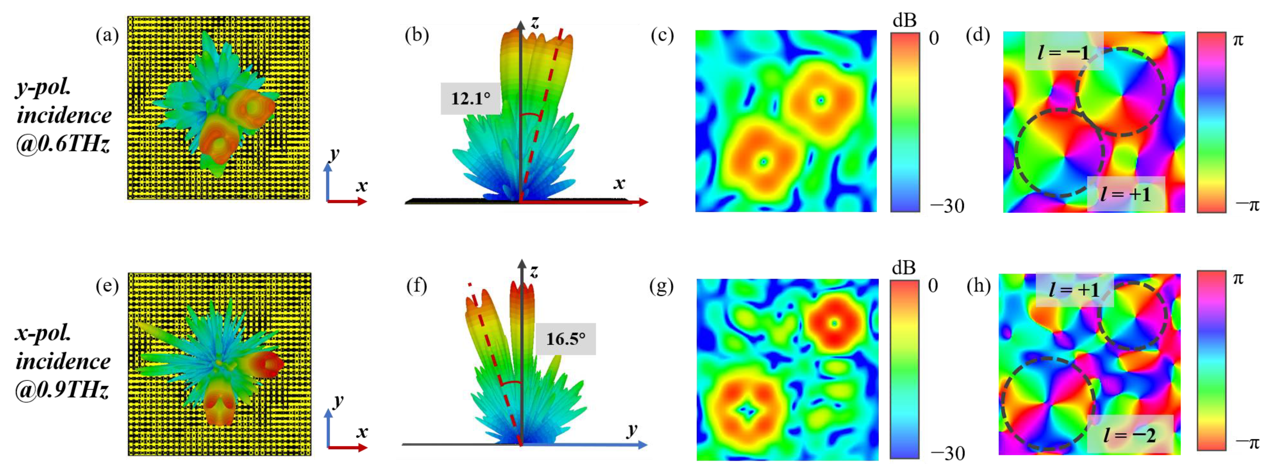
Figure 6 shows the full-wave simulated scattering field diagrams of the 3-bit coding multiple vortex beams metasurface. Figure 6a,b are the top and side views of the 3D far-field simulation diagrams at 0.6 THz under the y-polarized incidence. It should be noted that the far-field schematic of the yoz plane is the same as Figure 6b, which clearly illustrates two vortex beams with 12.1° deflection angle along both the x- and y-axis. Figure 6c,d are the 2D far-field amplitude and phase diagrams, respectively. It can be seen from these two images that the modes of two vortex beams are +1 and −1. Figure 6e,f present the top and side views of the 3D far-field simulation results at 0.9 THz under the x-polarized incidence. The generated vortex beams are deflected to 16.5° with respect to the x- and y-axis, which is almost the same as the preset deflection angle.The 2D far-field simulated amplitude and phase plots of the two vortex beams are then shown in Figure 6g,h, respectively, which are conformed to the characteristics of vortex beams ( l 3 = + 1 and l 4 = 2 ). Therefore, the 3-bit coding dual-function multiple vortex beams metasurfaceis verified by full-wave simulation to generatedualvortex beams with deflection angle of 12.1° along x- and y-axis at 0.6 THz under the y-polarized incidence and another dual vortex beams with deflection angle of 16.5°along x- and y-axis at 0.9 THz under the x-polarized incidence.
To sum up, generation of dual-band, dual-polarization, dual-beam and dual-mode vortex beams can be achieved simultaneously in the single metasurface. Moreover, the vortex beams with different deflection angles carrying different modes are generated in each operation band by applying addition and convolution operations flexibly according to the digital coding theories, which reduce the complexity of the design. In the design of unit cells, the reflection phases of two patterns can both cover 360°and be regulated independently. Furthermore, the reflection amplitudes are greater than 0.9 and 0.85 at 0.6 and 0.9 THz, respectively. The well reflection properties of unit cells provide the basis for 3-bit coding dual-band multiple vortex beams metasurface generator, where the OAM mode and deflection angle of each beam can be regulated independently.
The standard photolithography processes can be used to fabricate terahertz metasurfaces. Although it is not the main scope of this work to fabricate the proposed metasurface, we suggest the following steps for the production process [53]: (1) a gold layer can be deposited on a silicon wafer by electron beam evaporation; (2) the liquid polyimide can be uniformly deposited on the gold by spin-coating process and solidified at high temperature; (3) a polyimide layer with a thickness of 35 nm can be produced by repeating the spin-coating and curing process several times; (4) another gold layer can be deposited by electron beam evaporation; (5) the final metal pattern can be formed by the standard photolithography; (6) the metasurface can be peeled from the silicon substrate.

5. Conclusions

In summary, we propose a novel dual-band dual-polarization 3-bit coding single-layer reflective metasurface based on the beam polarization characteristics. The coding metasurface obtained by the convolution operation and addition operation can realize the combined multi-mode multiple vortex beams and beam deflections under orthogonal linearly polarized incidences at 0.6 and 0.9 THz. The full-wave simulation results are in good agreement with the theoretical calculation results, which verifies that the designed 3-bit coding metasurface is able to modulatecontrol terahertz wave flexibly. The dual-polarized dual-band multiple beam multi-mode orbital angular momentum generator designed in this work has serviceable and broad application prospects in future terahertz multiple-input multiple-output (MIMO) wireless communications.

Author Contributions

Conceptualization, L.S.; methodology, L.S., J.D. and P.T.; theories, P.T, X.Z., L.S. and J.D.; simulation analysis, P.T, X.Z., T.M., G.C., G.W., X.B. and H.S.; validation and data analysis, P.T., X.Z., T.M., G.C., G.W., X.B. and H.S.; writing—original draft preparation, L.S., P.T. and J.D.; writing—review and editing, L.S., P.T. and J.D.; supervision, L.S. and J.D. All authors have read and agreed to the published version of the manuscript.

Funding

This research was funded by the Beijing Natural Science Foundation of China–Haidian Original Innovation Joint Fund (Grant No. L222042), the National Key R&D Program of China (Grant No. 2022YFF0604801), the National Natural Science Foundation of China (Grant Nos. 62271056, 62171186, 62201037, and 61527805), the National Program on Key Basic Research Project (Grant No. 2019-JCJQ-ZD-349), the Beijing Natural Science Foundation (Grant No. 4154085), the Open Research Fund of State Key Laboratory of Space-Ground Integrated Information Technology (Grant No. 6142221200201), the Basic Research Foundation of Beijing Institute of Technology, China (Grant No. BITBLR2020014) and the 111 Project of China (Grant No. B14010).

Data Availability Statement

Data is contained within the article.

Conflicts of Interest

The authors declare no conflict of interest.

References

  1. Siegel, P.H. Terahertz Technology. IEEE Trans. Microw. Theory Tech. 2002, 50, 910–928. [Google Scholar] [CrossRef]
  2. Federici, J.F.; Schulkin, B.; Huang, F.; Gary, D.; Barat, R.; Oliveira, F.; Zimdars, D. THz imaging and sensing for security applications—explosives, weapons and drugs. Semicond. Sci. Technol. 2005, 20, S266–S280. [Google Scholar] [CrossRef]
  3. Appleby, R.; Anderton, R.N. Millimeter-wave and submillimeter-wave imaging for security and surveillance. Proc. IEEE 2007, 95, 1683–1690. [Google Scholar] [CrossRef]
  4. Ma, J.; Shrestha, R.; Adelberg, J.; Yeh, C.-Y.; Hossain, Z.; Knightly, E.; Jornet, J.M.; Mittleman, D.M. Security and Eavesdropping in Terahertz Wireless Links. Nature 2018, 563, 89–93. [Google Scholar] [CrossRef] [PubMed]
  5. Kleine-Ostmann, T.; Nagatsuma, T. A Review on Terahertz Communications Research. J. Infrared Millim. Terahertz Waves 2011, 32, 143–171. [Google Scholar] [CrossRef]
  6. Nagatsuma, T.; Ducournau, G.; Renaud, C.C. Advances in Terahertz Communications Accelerated by Photonics. Nat. Photonics 2016, 10, 371–379. [Google Scholar] [CrossRef]
  7. Woolard, D.L.; Brown, R.; Pepper, M.; Kemp, M. Terahertz frequency sensing and imaging: A time of reckoning future applications? Proc. IEEE 2005, 93, 1722–1743. [Google Scholar] [CrossRef]
  8. Mittleman, D.M. Twenty Years of Terahertz Imaging [Invited]. Opt. Express 2018, 26, 9417–9431. [Google Scholar] [CrossRef]
  9. Hillger, P.; Grzyb, J.; Jain, R.; Pfeiffer, U.R. Terahertz imaging and sensing applications with silicon-based technologies. IEEE Trans. Terahertz Sci. Technol. 2019, 9, 1–19. [Google Scholar] [CrossRef]
  10. Siegel, P.H. Terahertz Technology in Biology and Medicine. IEEE Trans. Microw. Theory Tech. 2004, 52, 2438–2447. [Google Scholar] [CrossRef]
  11. Yao, A.M.; Padgett, M.J. Orbital angular momentum: Origins, behavior and applications. Adv. Opt. Photonics 2011, 3, 161–204. [Google Scholar] [CrossRef] [Green Version]
  12. Allen, L.; Beijersbergen, M.W.; Spreeuw, R.J.C.; Woerdman, J.P. Orbital angular momentum of light and the transformation of Laguerre-Gaussian laser modes. Phys. Rev. A 1992, 45, 8185–8189. [Google Scholar] [CrossRef] [PubMed]
  13. Tamburini, F.; Thidé, B.; Della Valle, M. Measurement of the spin of the M87 black hole from its observed twisted light. Mon. Not. R. Astron. Soc. Lett. 2020, 492, L22–L27. [Google Scholar] [CrossRef] [Green Version]
  14. Cojoc, D.; Garbin, V.; Ferrari, E.; Businaro, L.; Romanato, F.; Fabrizio, E.D. Laser trapping and micro-manipulation using optical vortices. Microelectron. Eng. 2005, 78–79, 125–131. [Google Scholar]
  15. Wang, B.; Tanksalvala, M.; Zhang, Z.; Esashi, Y.; Jenkins, N.W.; Murnane, M.M.; Kapteyn, H.C.; Liao, C.-T. Coherent Fourier scatterometry using orbital angular momentum beams for defect detection. Opt. Express 2021, 29, 3342–3358. [Google Scholar] [CrossRef] [PubMed]
  16. McCarter, M.R.; Saleheen, A.I.U.; Singh, A.; Tumbleson, R.; Woods, J.S.; Tremsin, A.S.; Scholl, A.; DeLong, L.E.; Hastings, J.T.; Morley, S.A.; et al. Antiferromagnetic real-space configuration probed by dichroism in scattered X-ray beams with orbital angular momentum. Phys. Rev. B 2023, 107, L060407. [Google Scholar] [CrossRef]
  17. Wilig, K.I.; Rizzoli, S.O.; Westphal, V.; Jahn, R.; Hell, S.W. STED microscopy reveals that synaptotagmin remains clustered after synaptic vesicle exocytosis. Nature 2006, 440, 935–939. [Google Scholar] [CrossRef]
  18. Wang, B.; Brooks, N.J.; Johnsen, P.C.; Jenkins, N.W.; Esashi, Y.; Tanksalvala, M.; Kapteyn, H.C.; Murnane, M.M. High-fidelity ptychographic imaging of highly periodic structures enabled by vortex high harmonic beams. arXiv 2023, 2301, 05563. [Google Scholar]
  19. Taburini, F.; Mari, E.; Sponselli, A.; Thidé, B.; Bianchini, A.; Romanato, F. Encoding many channels on the same frequency through radio vorticity: First experimental test. New J. Phys. 2012, 14, 033001. [Google Scholar] [CrossRef] [Green Version]
  20. Thidé, B.; Then, H.; Sjöholm, J.; Palmer, K.; Bergman, J.; Carozzi, T.D.; Istomin, Y.N.; Ibragimov, N.H.; Khamitova, R. Utilization of photon orbital angular momentum in the low-frequency radio domain. Phys. Rev. Lett. 2007, 99, 087701. [Google Scholar]
  21. Mahmoli, F.E.; Walker, S.D. 4-Gbps uncompressed video transmission over a 60-GHz orbital angular momentum wireless channel. IEEE Wirel. Commun. Lett. 2013, 2, 223–226. [Google Scholar] [CrossRef]
  22. Nagli, E.; Sciarrino, F.; DeMartini, F.; Marrucci, L.; Piccirillo, B.; Karimi, E.; Santamato, E. Quantum information transfer from spin to orbital angular momentum of photons. Phys. Rev. Lett. 2009, 103, 013601. [Google Scholar] [CrossRef] [PubMed] [Green Version]
  23. Cheng, L.; Hong, W.; Hao, Z.-C. Generation of electromagnetic waves with arbitrary orbital angular momentum modes. Sci. Rep. 2014, 4, 4814. [Google Scholar] [CrossRef] [PubMed] [Green Version]
  24. Khonina, S.N.; Podlipnov, V.V.; Karpeev, S.V.; Ustinov, A.V.; Volotovsky, S.G.; Ganchevskaya, S.V. Spectral control of the orbital angular momentum of a laser beam based on 3D properties of spiral phase plates fabricated for an infrared wavelength. Opt. Express 2020, 28, 18407–18417. [Google Scholar] [CrossRef]
  25. Guo, Z.-G.; Yang, G.-M. Radial uniform circular antenna array for dual-mode OAM communication. Antennas Wirel. Propag. Lett. 2017, 16, 404–407. [Google Scholar] [CrossRef]
  26. Liu, Q.; Chen, Z.N.; Liu, Y.; Li, F.; Chen, Y.; Mo, Z. Circular polarization and mode reconfigurable wideband orbital angular momentum patch array antenna. IEEE Trans. Antennas Propag. 2018, 66, 1796–1804. [Google Scholar] [CrossRef]
  27. Xie, Z.; Wang, X.; Ye, J.; Feng, S.; Sun, W.; Akalin, T.; Zhang, Y. Spatial Terahertz Modulator. Sci. Rep. 2013, 3, 3347. [Google Scholar] [CrossRef] [Green Version]
  28. Knyazev, B.A.; Choporova, Y.Y.; Mitkov, M.S.; Pavelyev, V.S.; Volodkin, B.O. Generation of terahertz surface plasmon polaritons using nondiffractive Bessel beams with orbital angular momentum. Phys. Rev. Lett. 2015, 115, 163901. [Google Scholar] [CrossRef]
  29. Zhang, H.; Si, L.; Ma, T.; Dong, L.; Niu, R.; Bao, X.; Sun, H.; Ding, J. Triple-Band Terahertz Chiral Metasurface for Spin-Selective Absorption and Reflection Phase Manipulation. Electronics 2022, 11, 4195. [Google Scholar] [CrossRef]
  30. Zhang, K.; Yuan, Y.; Zhang, D.; Ding, X.; Ratni, B.; Burokur, S.N.; Lu, M.; Tang, K.; Wu, Q. Phase-engineered metalenses to generate converging and non-diffractive vortex beam carrying orbital angular momentum in microwave region. Opt. Express 2018, 26, 1351–1360. [Google Scholar] [CrossRef]
  31. Cheng, G.; Si, L.; Tang, P.; Zhuang, Y.; Sun, H.; Ding, J. Topology optimization of the azimuth-rotation-independent polarization conversion metasurface for bandwidth enhancement. Opt. Express 2022, 30, 41340–41349. [Google Scholar] [CrossRef]
  32. Wong, A.M.H.; Eleftheriades, G.V. Perfect anomalous reflection with a bipartite Huygens’ metasurface. Phys. Rev. X 2018, 8, 011036. [Google Scholar] [CrossRef] [Green Version]
  33. Zhao, H.; Li, B.; Zhou, J.; Kang, L.; Zhao, Q.; Li, W. Abnormal refraction of microwave in ferrite/wire metamaterials. Opt. Express 2011, 19, 15679–15689. [Google Scholar] [CrossRef] [PubMed]
  34. Khorasaninejad, M.; Chen, W.T.; Devlin, R.C.; Oh, J.; Zhu, A.Y.; Capasso, F. Metalenses at visible wavelengths: Diffraction-limited focusing and subwavelength resolution imaging. Science 2016, 352, 1190–1194. [Google Scholar] [CrossRef] [PubMed] [Green Version]
  35. Ni, X.; Ishii, S.; Kildishev, A.V.; Shalaev, V.M. Ultra-thin, planar, Babinet-inverted plasmonic metalenses. Light. Sci. Appl. 2013, 2, e72. [Google Scholar] [CrossRef] [Green Version]
  36. Yin, X.; Ye, Z.; Rho, J.; Wang, Y.; Zhang, X. Photonic Spin Hall Effect at Metasurfaces. Science 2013, 339, 1405–1407. [Google Scholar] [CrossRef] [Green Version]
  37. Li, Z.; Liu, W.; Cheng, H.; Chen, S.; Tian, J. Manipulation of the Photonic Spin Hall Effect with High Efficiency in Gold-Nanorod-Based Metasurfaces. Adv. Opt. Mater. 2017, 5, 1700413. [Google Scholar] [CrossRef]
  38. Ni, X.; Wong, Z.J.; Mrejen, M.; Wang, Y.; Zhang, X. An ultrathin invisibility skin cloak for visible light. Science 2015, 349, 1310–1314. [Google Scholar] [CrossRef]
  39. Yang, Y.; Jing, L.; Zheng, B.; Hao, R.; Yin, W.; Li, E.; Soukoulis, C.M.; Chen, H. Full-polarization 3D metasurface cloak with preserved amplitude and phase. Adv. Mater. 2016, 28, 6866–6871. [Google Scholar] [CrossRef]
  40. Ni, X.; Kildishev, A.V.; Shalaev, V.M. Metasurface Holograms for Visible Light. Nat. Commun. 2013, 4, 2807. [Google Scholar] [CrossRef] [Green Version]
  41. Li, L.; JunCui, T.; Ji, W.; Liu, S.; Ding, J.; Wan, X.; BoLi, Y.; Jiang, M.; Qiu, C.-W.; Zhang, S. Electromagnetic reprogrammable coding-metasurface holograms. Nat. Commun. 2017, 8, 197. [Google Scholar] [CrossRef] [Green Version]
  42. Lei, Z.; Jiu-sheng, L. Transmission type Dual-frequency Vortex Beams Generator for Multiple OAM Modes. Opt. Quant. Electron. 2022, 54, 209. [Google Scholar] [CrossRef]
  43. Xie, R.; Fang, X.; Zhang, D.; Wang, X.; Chen, K.; An, S.; Zheng, B.; Zhang, H.; Feng, Y.; Ding, J. Four-Channel Kaleidoscopic Metasurfaces Enabled by a Single-Layered Single-Cell Quad-Band Meta-Atom. Adv. Theory Sims. 2022, 5, 2100301. [Google Scholar] [CrossRef]
  44. Tang, Z.; Li, L.; Zhang, H.; Yang, J.; Hu, J.; Lu, X.; Hu, Y.; Qi, S.; Liu, K.; Tian, M.; et al. Multifunctional Janus metasurfaces achieving arbitrary wavefront manipulation at dual frequency. Mater. Des. 2022, 223, 111264. [Google Scholar] [CrossRef]
  45. Li, J.-S.; Zhang, L.-N. Simple terahertz vortex beam generator based on reflective metasurfaces. Opt. Express 2020, 28, 36403–36412. [Google Scholar] [CrossRef] [PubMed]
  46. Li, J.-S.; Pan, W.-M. Combination regulation of terahertz OAM vortex beams on multi-bit metasurface. J. Phys. D Appl. Phys. 2022, 55, 235103. [Google Scholar] [CrossRef]
  47. Wang, T.; Xie, R.; Zhu, S.; Gao, J.; Xin, M.; An, S.; Zheng, B.; Li, H.; Lin, Y.; Zhang, H.; et al. Dual-band high efficiency terahertz meta-devices based on reflective geometric metasurfaces. IEEE Access 2019, 7, 58131–58138. [Google Scholar] [CrossRef]
  48. Ji, C.; Song, J.; Huang, C.; Wu, X.; Luo, X. Dual-band vortex beam generation with different OAM modes using single-layer metasurface. Opt. Express 2019, 27, 34–44. [Google Scholar] [CrossRef]
  49. Li, J.; Guo, F.; Zhang, S.; Liu, C. Bidirectional Terahertz Vortex Beam Regulator. Materials 2022, 15, 8639. [Google Scholar] [CrossRef]
  50. Jie, C.; Jiu-sheng, L. Reflective type metasurface for generating and regulating vortex beam at two frequencies. Opt. Commun. 2022, 524, 128758. [Google Scholar] [CrossRef]
  51. Wu, R.Y.; Shi, C.B.; Liu, S.; Wu, W.; Cui, T.J. Addition theorem for digital coding metamaterials. Adv. Opt. Mater. 2018, 6, 1701236. [Google Scholar] [CrossRef]
  52. Liu, S.; Cui, T.J.; Zhang, L.; Xu, Q.; Wang, Q.; Wan, X.; Gu, J.Q.; Tang, W.X.; QingQi, M.; Han, J.G.; et al. Convolution operations on coding metasurface to reach flexible and continuous controls of terahertz beams. Adv. Sci. 2016, 3, 1600156. [Google Scholar] [CrossRef]
  53. Liu, S.; Cui, T.J.; Xu, Q.; Bao, D.; Du, L.; Wan, X.; Tang, W.X.; Ouyang, C.; Zhou, X.Y.; Yuan, H.; et al. Anisotropic coding metamaterials and their powerful manipulation of differently polarized terahertz waves. Light. Sci. Appl. 2016, 5, e16076. [Google Scholar] [CrossRef] [Green Version]
  54. Lin, C.; Li, G.Y.L. Terahertz Communications:An Array-of-Subarrays Solution. IEEE Commun. Mag. 2016, 54, 124–131. [Google Scholar] [CrossRef]
  55. Nanfang, Y.; Genevet, P.; Kats, M.A.; Aieta, F.; Tetienne, J.-P.; Capasso, F.; Gaburro, Z. Light propagation with phase discontinuities: Generalized laws of reflection and refraction. Science 2011, 334, 333–337. [Google Scholar]
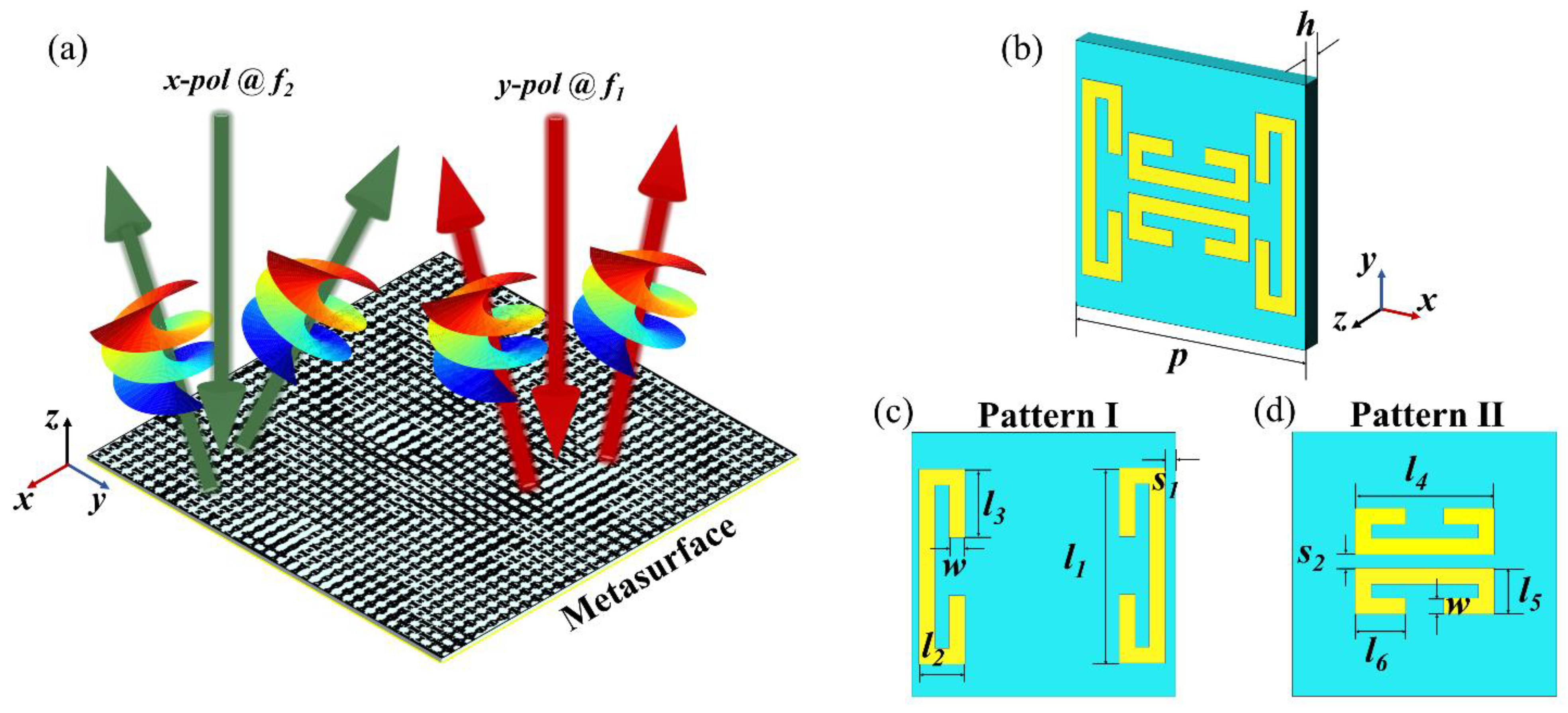
Figure 1. (a) Schematic illustration of the vortex beam generator based on the 3-bit coding reflective metasurface. (b) Three-dimensional view of the metasurface unit cell; the unit cell is a combination of (c) Pattern I and (d) Pattern II.
Electronics 12 01868 g001
Figure 2. Reflection amplitude and phase of the proposed 64 metasurface unit cells. (‘*’ represents any integer from 1 to 8.) (a,c) are reflection phase and amplitude distribution with y-polarized plane wave incidence at 0.6 THz. (b,d) are reflection phase and amplitude distribution with x-polarized plane wave incidence at 0.9 THz.
Electronics 12 01868 g002
Figure 3. Phase distribution of the single beam dual-function OAM generator based on 3-bit coding unit cells. (Here, ‘*’ means the convolution operation.) (a) Phase distribution of the l 1 = + 1 deflected vortex beam at 0.6 THz under the y-polarized incidence. (b) Phase distribution of the l 2 = + 1 deflected vortex beam at 0.9 THz under the x-polarized incidence.
Electronics 12 01868 g003
Figure 4. Full-wave simulated scattering field diagrams of the single vortex beam metasurface. (a) Top view and (b) side view of the 3D far-field simulation scattering diagrams; (c) magnitude and (d) phase of the 2D far-field partial diagrams of the l 1 = + 1 deflected vortex beam at 0.6 THz under the y-polarized incidence. (e) Top view and (f) side view of the 3D far-field simulation scattering diagrams; (g) magnitude and (h) phase of the 2D far-field partial diagrams of the l 2 = + 1 deflected vortex beam at 0.9 THz under the x-polarized incidence.
Electronics 12 01868 g004
Figure 5. Phase distribution of the multiple beams dual-function OAM generator based on 3-bit coding unit cells. (Here, ‘*’ means the convolution operation). (a) Phase distribution of the l 1 = + 1 and l 2 = 1 deflected vortex beams at 0.6 THz under the y-polarized incidence. (b) Phase distribution of the l 3 = + 1 and l 4 = 2 deflected vortex beams at 0.9 THz under the x-polarized incidence.
Electronics 12 01868 g005
Figure 6. Full-wave simulated scattering field diagrams of the multiple vortex beams metasurface. (a) Top view and (b) side view of the 3D far-field simulation scattering diagrams; (c) magnitude and (d) phase of the 2D far-field partial diagrams of the l 1 = + 1 and l 2 = 1 deflected vortex beams at 0.6 THz under the y-polarized incidence. (e) Top view and (f) side view of the 3D far-field simulation scattering diagrams; (g) magnitude and (h) phase of the 2D far-field partial diagrams of the l 3 = + 1 and l 4 = 2 deflected vortex beams at 0.9 THz under the x-polarized incidence.
Electronics 12 01868 g006
Table 1. Parameters of the eight structures of Pattern I.
Pattern I*/1*/2*/3*/4*/5*/6*/7*/8
l 1 ( μ m ) 7095103102105115120130
l 3 ( μ m ) 101512202111.51537
Phase (°)04590135180215270315
Code000001010011100101110111
Table 2. Parameters of the eight structures of Pattern II.
Pattern II1/*2/*3/*4/*5/*6/*7/*8/*
l 4 ( μ m ) 4057626569748080
l 6 ( μ m ) 101010.511.210.5101533
Phase (°)04590135180215270315
Code000001010011100101110111
Disclaimer/Publisher’s Note: The statements, opinions and data contained in all publications are solely those of the individual author(s) and contributor(s) and not of MDPI and/or the editor(s). MDPI and/or the editor(s) disclaim responsibility for any injury to people or property resulting from any ideas, methods, instructions or products referred to in the content.