Abstract
Electric distribution grids are seeing an increased penetration of photovoltaic (PV) generation. High PV generation exceeding the grid load demand results in a reverse active power flow in the grid, which raises the voltage level. This paper presents a reactive power controller to overcome the overvoltage problem in the distribution system. A sequentially coordinated and cooperative volt/var control technique is presented. The proposed controller aims to use as low reactive power as possible while mitigating the voltage issues. Accordingly, it reduces the active power loss associated with reactive power flow and reduces the probability for active power curtailment of the PV system. The controller is developed for each lateral and is replicated for all laterals. The lateral controller coordinates the operation of the smart PV inverters in a sequential manner. Cooperative control is proposed between the laterals’ controllers as well and is engaged when the individual laterals’ controllers are unable to solve their overvoltage issues. The performance of the proposed controller is evaluated by comparing it to two other volt/var controllers, and it demonstrates better performance in terms of reactive power requirement. To conduct the simulation study, a modified version of the unbalanced IEEE 13-bus system is utilized, which includes an additional 44 low-voltage bus. The study involves simulating 720 operating points across daily time series. The results indicate that the proposed controller effectively addresses overvoltage problems that occur during periods of high PV generation.
1. Introduction
The world is becoming more dependent on clean and renewable energy sources as a result of actions to counteract climate change and other environmental factors [1,2]. As shown in Figure 1 [3], solar power had the highest share among the various renewable energy source installations in the world in 2021. The operation and management of the electric grids are challenged in several ways by photovoltaic (PV) systems, despite their financial, technical, and environmental benefits [4,5,6]. In a conventional radial distribution system, active power flows from the main substation to the loads. However, with a high level of PV penetration into the distribution grid, this assumption is not always satisfied where active power may flow upstream from the load points to the main substation, which is referred to as the reverse power flow problem [7]. Reverse power flow occurs when the net PV generation exceeds the load demand and may lead to voltage rise at the load points, violating the acceptable operational upper voltage limit [8,9]. PV systems are derived by smart inverters to regulate and maximize generated power. This paper extends the work firstly reported in [10] and focuses on approaches that use PV smart inverters to address the overvoltage issue instead of relying on more traditional devices such as voltage regulators.
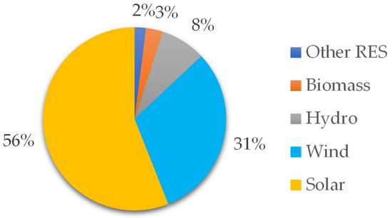
Figure 1.
Installed renewable power generation relative capacity in 2021 [3].
International standards currently consider the participation of the smart inverters in voltage control, e.g., IEEE standard 1547 [11]. Voltage control could be accomplished through reactive power (volt/var) control and/or active power (volt/watt) control [11,12]. Due to high R/X ratio for the distribution grids, the voltage sensitivity to change in active power is higher than its sensitivity to change in reactive power [13]. Nevertheless, the volt/watt depends on active power curtailment, which negatively affects the financial return from the PV system. Therefore, the volt/var control is more acceptable. The PV inverter changes its reactive power based on the voltage magnitude. In case of undervoltage, the PV inverter injects reactive power to the system to increase the voltage level. On the other hand, the inverter absorbs reactive power from the system if the voltage exceeds the upper voltage setting. The characteristics of the standard volt/var controller will be presented later in the paper. The default configuration for the volt/var controller specified in IEEE standard 1547 has been tested against a number of operational scenarios in [14] and has proven to be effective for regulating the voltage. The increased thermal overloading of the network cables and transformers is one of the downsides and restrictions of the volt/var droop control system [15].
Instead of using the default volt/var droop setting as specified in [11] for all inverters in the system, an optimized setting was proposed in [16] where a different setting was allocated to different inverters. The PV inverters were coordinated based on their droop setting, which was deduced from solving a multi-objective optimization problem. The optimization problem was formulated at a critical operating point where the droop settings were the control variables. Using different settings for different inverters resulted in better performance in terms of reactive power requirements. In [17], the reactive power setting was related to the output active power from the PV system. Specifically, the PV system was designed to absorb reactive power when the active power surpassed a certain threshold level. To determine the appropriate threshold level and droop setting for different PV systems, an optimization problem was solved to minimize the associated power loss. However, the estimated settings in [16,17] may not be optimum at different operating conditions. A combined voltage control method was proposed in [18] where a new characteristic was developed from combing reactive power control based on voltage Q(V) and power factor control based on active power PF(P). The reactive power reference value was calculated as the weighted sum of the reference values resulting from the Q(V) and PF(P) controllers. With the aid of communication between various PV systems, two reactive power control methods were proposed in [19]. These two methods relied on either low or high bandwidth communication means. The first method used information about reactive power from all inverters to set the controller slope, with the goal of equalizing the reactive power sharing between the inverters. Meanwhile, the second method used measured active power from all inverters to solve an optimization problem and set the droop slope. The second approach aimed to regulate voltage and minimize power loss. Despite the superior performance of the second method, it is more expensive. Voltage control at the lateral level was developed in [20]. A controller was suggested for each lateral using voltage measurement at the lateral’s end node and the measured active power generation from all PV systems. The controller depended on the system voltage sensitivity matrix, which was calculated offline. Another option to mitigate the voltage violation is the installation of energy storage systems. Charging an energy storage system when there is an extra PV generation was suggested in [21] to avoid the overvoltage issue in the system and discharging this energy during the system’s peak loading periods as needed. As previously mentioned, the voltage can be controlled through the active power [17]. The effectiveness of active power and reactive power control methods to solve the voltage rise problem due to high PV generation in a Malaysian distribution grid was studied in [12]. Coordination between different voltage control devices such as capacitor banks, on-load tap changers, and PV inverters is also a potential application for the PV inverters that facilitates the PV penetration into the distribution grids [22]. In [23], a central controller was proposed that used an optimization technique to determine the reactive power setpoints for the central dispatch of reactive power. The aim was to minimize the system active power loss while also estimating the droop settings for the local controllers to respond to changes in real-time PV output power. Implementing a central controller requires a sophisticated and expensive communication infrastructure, as well as a thorough understanding of system information, and adds a substantial computational burden [24].
The literature review demonstrates the need for additional study regarding the integration of PV systems into the distribution network and the resulting voltage issues. This paper extends the work presented in [10]. A sequential coordinated and cooperative controller at the lateral level is proposed to mitigate the overvoltage problem. The sequential coordinated control ensures the coordination between different inverters to utilize as low reactive power as possible. The cooperative control is activated if the individual controllers are unable to solve their overvoltage problem. In comparison to other lateral level controllers and local controllers, the suggested controller offers the following advantages:
- It does not require measuring/communicating the active power data. Therefore, a low bandwidth communication channel would suffice;
- It uses as little reactive power as possible, therefore reducing the chances for active power curtailment due to reactive power requirement, which increases the profitability of the PV system. Active power curtailment occurs if the inverter-rated apparent power does not allow both active power and reactive power flow;
- There is no need for droop settings, unlike the local droop controllers;
- The coordination between the inverters is satisfied at different load and PV operating conditions.
The rest of the paper is organized as follows. Section 2 presents the principles of the standard volt/var droop control method as described in IEEE standard 1547-2018. The proposed sequential control method is presented in Section 3. The proposed controller is compared to two other controllers in Section 4. Section 5 presents the simulation results and discussion on a modified version of the IEEE 13-bus feeder. Finally, the conclusions are presented in Section 6.
2. State of the Art Volt/Var Droop Control
The volt/var droop control is briefly explained before moving on to the suggested controller because it will serve as the foundation for a comparison study in a later section. According to IEEE standard 1547-2018, distributed resources must take part in voltage regulation utilizing a variety of control strategies [11]. The commonly used control strategy is the volt/var droop control method, which employs the characteristics shown in Figure 2. [14,25]. Based on the voltage magnitude, the inverter changes its reactive power (over-excited, under-excited, or unity power factor). The droop controller requires setting the voltage and reactive power values indicated by the four points in Figure 2. If the system exhibits an overvoltage, the inverter absorbs reactive power, following its setting, to reduce the system voltage and does the opposite if there is an undervoltage situation. Setting the droop controller and coordinating different controllers is a tricky point if the accompanied active power loss is considered [10,16].
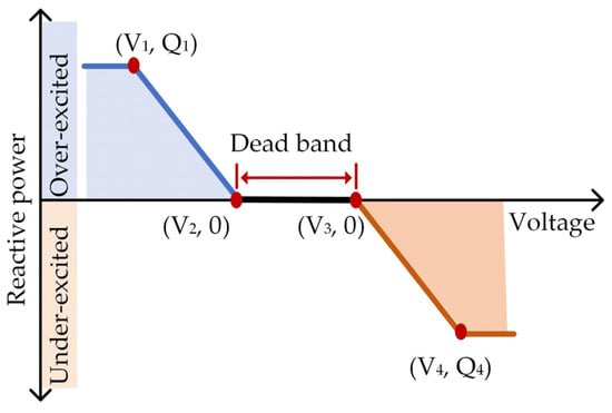
Figure 2.
IEEE standard 1547-2018 volt/var control characteristics [11].
3. Proposed Controller
A controller is used for each lateral governing the lateral voltage through utilization of the reactive power capabilities of the smart PV inverters installed along the lateral as shown in Figure 3. Once an overvoltage is detected, the lateral controller adjusts the reactive power setpoint (reference) for the inverter control algorithm. The inverter control algorithm itself can be a PI controller, and its design is outside of this paper’s scope. The proposed controller can be a separate unit. However, it can be integrated as a function within one of the smart PV inverters and is referred to as the “Lateral Leader”. The lateral leader is selected as the most downstream inverter along the lateral as it will see the maximum voltage value in case of overvoltage [16]. The lateral leader monitors its local voltage and acts if the voltage exceeds the permitted limit. During an overvoltage situation, the inverter is required to absorb reactive power to reduce the voltage (under-excited mode [11]). This reactive power flow results in active power loss on the distribution cables/lines. Therefore, it is not only necessary to solve the overvoltage problem but to minimize the associated active power loss as well.
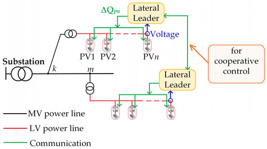
Figure 3.
Proposed lateral based controller.
To solve the voltage violation issue in the system under various operating conditions, the proposed control approach tries to use as little reactive power as possible. The overvoltage issue can be resolved by using the arbitrary/default droop setting from IEEE standard 1547 [14,15], although doing so may result in consuming more reactive power than is necessary, increasing active power loss. The power loss caused by reactive power flow can be decreased by optimizing the droop setting between various PV systems [16]. However, the coordination of the functioning of the PV systems is often done at a single operating point (ideally a critical point). Therefore, not all operational conditions may result in the minimum reactive power use being met.
In Figure 3, a lateral leader dispatches reactive power to one of the inverters along the lateral at a time. The sensitivity of a bus/node voltage to a change in reactive power increases while moving downstream along the lateral [26]. Therefore, the lateral leader, at the most downstream inverter, controls firstly the reactive power of its inverter. The inverter reactive power setpoint (Qset) is recursively changed by an amount of (∆Qpu) until any of the following conditions is met:
- The voltage violation case is solved;
- The inverter is absorbing its maximum reactive power (Qmax).
If the second condition is satisfied while the first is not, the controller moves to controlling the reactive power setpoint of the next inverter and so on as shown in Figure 4. The change in the reactive power ∆Qpu can be a fixed value or varies during the control iterations according to the voltage deviation level. A fixed value of 0.05 pu is used in this study. According to IEEE standard 1547 [11], the maximum reactive power of a PV inverter is 0.44 pu in the under-excited mode.
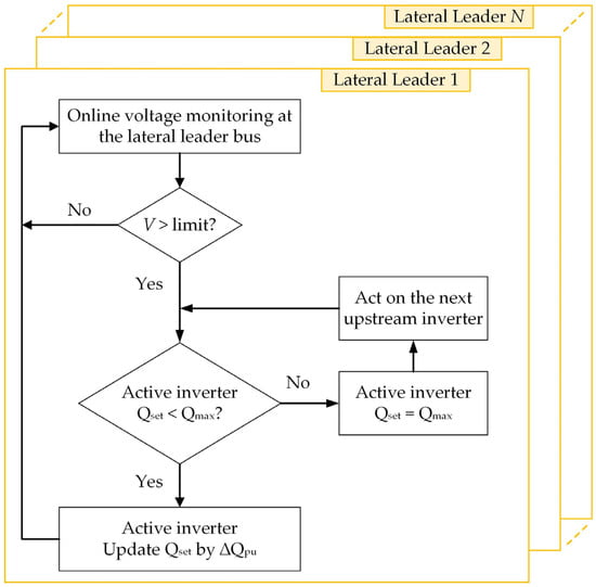
Figure 4.
Sequential operation of the lateral leader.
Different leaders operate independently following the procedure in Figure 4. However, it might happen that all the PV inverters along a lateral absorb their maximum reactive power without solving the overvoltage problem. Under these circumstances, cooperation between different leaders can help solve the problem. This is referred to as “cooperative control” and is activated when necessary. A lateral leader that cannot individually solve its lateral voltage problem seeks help from another leader. The online cooperative control follows the procedure in Figure 5.
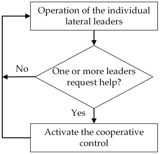
Figure 5.
Combining individual and cooperative controls.
For a certain leader, what is the best order of other leaders to support it? This question is answered through carrying out a voltage sensitivity analysis for the system [26]. The analysis can be done by activating only one leader at a time and checking the corresponding effect on the voltage of the other leaders. In the results section, a numerical example for this sensitivity study is provided on a modified version of the IEEE 13-bus system.
Unlike the sequence used to control the PV inverters along a lateral during the lateral leader individual operation, which starts by the lateral leader bus then moves upstream to the other inverters as needed, the cooperative control starts by the most upstream inverter on the lateral. To help illustrate this point, assume the lateral leader “m” in Figure 3 requires help from the lateral leader “k” to solve the overvoltage problem on lateral “m”. The voltage variation at bus “m” due to a change in the reactive power of a PV system “j” along the lateral “k” is constant for different “j” (i.e., ∂Vm/∂Qjk = constant, for different “j”). Therefore, when the lateral leader “k” is called by the cooperative control, it starts acting on the first PV system near the lateral head because it results in lower active power loss compared to the rest of the inverters along the lateral (lower distance is lower loss). In other words, a lateral leader “k” starts by “PVn” during its individual operation in case of an overvoltage on the lateral “k” and starts by “PV1” during the cooperative control.
In comparison to other lateral level controllers [20] and local droop controllers [16], the suggested controller offers the following advantages:
- Unlike [20], the proposed controller does not require measuring/communicating power data. Therefore, a low bandwidth communication channel would suffice;
- It uses as little reactive power as possible, therefore reducing the chances for active power curtailment due to reactive power requirement, which increases the profitability of the PV system. Active power curtailment occurs if the inverter-rated apparent power does not allow both active power and reactive power flow;
- There is no need for droop settings, unlike the local droop controllers;
- The coordination between the inverters is satisfied at different operating conditions.
4. Comparative Study
The proposed controller is compared to two other volt/var controllers [11,16]. The control methods in [11,16] depend on the droop control concept shown in Figure 2. The comparison was performed on the system used in [16], which is depicted in Figure 6. Parameters of the low voltage system are given in Table 1. The IEEE standard 1547-2018 provides a potential range for each of the droop control parameters with a default setting indicated [11]. It has been shown in [20] that the arbitrary droop setting achieves a similar performance to the voltage sensitivity-based droop setting. The study in [14] emphasized the ability of the default settings to overcome the voltage problem. Accordingly, the default droop setting was applied when testing the method in [11].
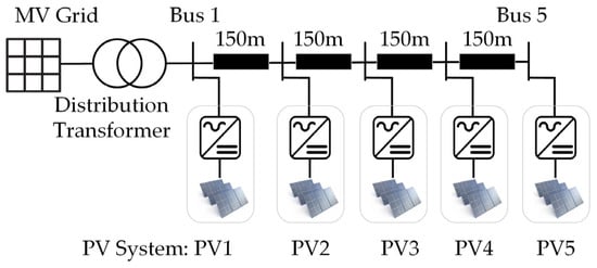
Figure 6.
Simulated distribution system used in [16].

Table 1.
Parameters of the low voltage lateral.
On the other hand, an optimized setting was employed in [16]. The setting was derived from solving an optimization problem at a critical operating point as detailed in [16]. The derived setting for the under-excited operating zone is shown in Table 2. The reactive power values in Table 2 are based on the kW rating of the PV system, not the kVA rating [16]. The Open Distribution System Simulator (OpenDSS) program was used to model the system including the PV systems [27]. OpenDSS allows other programs such as MATLAB/Python to run and control the simulation via the program’s COM interface. The proposed controller was modelled using MATLAB and was applied to the distribution system modelled on OpenDSS via the COM interface. In order to match the simulation conditions in [16], the following points were considered:

Table 2.
Optimized droop setting according to [16].
- The system was unloaded such that the generated PV active power flows to the main substation, which results in an increase in the system voltage;
- An upper voltage limit of 1.1 pu, following EN 50160 [28], was used;
- The total generated power was increased up to 150 kW.
Figure 7 shows the voltage profile along the system at total PV generation of 75 kW, 100 kW, and 150 kW. Reverse power flow resulted in an increase in the voltage, while moving downstream, that may exceed the upper voltage limit depending on the generated power. The standard volt/var control (standard) [11], the optimized-setting volt/var control (optimized) [16], and the proposed volt/var control (proposed) methods were applied individually to the system at different generation levels Figure 8 shows the voltage at the last bus (bus 5) before and after applying the control for generation level from 100 kW to 150 kW. The three control methods successfully solved the overvoltage problem. The three controllers show a difference in the point at which the control started its action. The proposed controller only reacted at 127 kW, while the optimized-setting controller [16] started around 115 kW, and the IEEE standard controller was acting over the entire generation range presented. The PV systems absorb reactive power from the system to bring the voltage down. Therefore, excessive reaction of the controller results in absorbing more reactive power, which increases the system power loss. The absorbed reactive power as a percentage of the PV systems reactive power capability is shown in Figure 9.
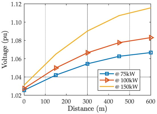
Figure 7.
Voltage profile at different generated power levels before applying any control.
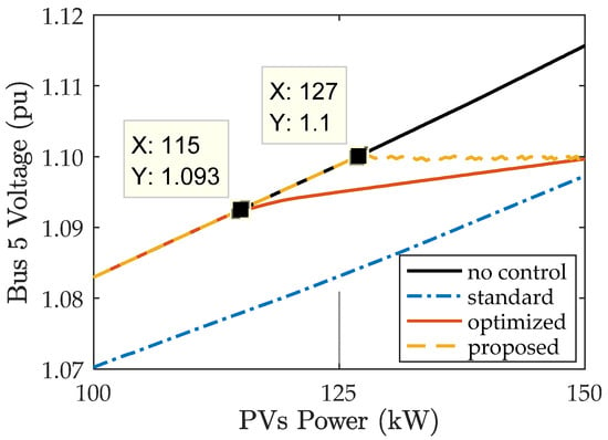
Figure 8.
Voltage at bus 5 at different generated active power levels.
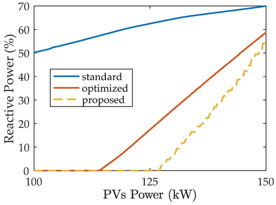
Figure 9.
Percentage absorbed reactive power at different active power levels.
As is clear, the standard IEEE controller resulted in absorbing at least 50% of the total reactive power capability. The optimized-setting controller provides an improved performance. The proposed controller has the lowest reactive power requirement. It is worth noting that if the PV smart inverter kVA rating is equal to the PV system kW, absorbing reactive power may require reducing the generated active power, which is known as active power curtailment [20]. Therefore, it is better to absorb as little reactive power as possible to:
- Reduce the active power loss associated to the reactive power flow;
- Avoid the need for large active power curtailment if the inverter cannot provide both active power and reactive power, which increases the profitability of the PV system.
The comparison shows that the proposed controller dominates the other two controllers in terms of reactive power requirement.
5. Results and Discussion
In this section, the proposed controller was applied to a modified version of the IEEE 13-bus feeder. Firstly, voltage sensitivity analysis to reactive power change was performed as a part of the cooperative control. Then, time series simulation was used to evaluate the performance of individual and cooperative controllers under different load and PV generation profiles.
5.1. System Description
The unbalanced IEEE 13-bus medium voltage system was used in this study [29]. The system was modified by:
- Fixing the regulator tap position at the main substation;
- Disconnecting the capacitor banks at buses 675 and 611;
- Adding eleven low voltage laterals.
The modified system is shown in Figure 10 with five three-phase laterals connected at buses 633, 675, 680, and 671 and six single-phase laterals connected at buses 692, 652, 611, 645, and 646. Description and data for the IEEE-13 bus feeder is available in [29], while the data for the added laterals is given in Appendix A. The distribution system was simulated using the OpenDSS program [27]. Figure 11 shows the voltage profile when all loads and PV systems were operating at the rated power, along the feeder where the main substation lies at the zero distance. The unbalanced nature of the system is clear from Figure 11 noting that the PV systems were operating at unity power factor.
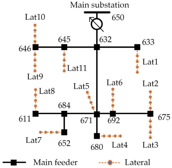
Figure 10.
Simulated modified IEEE 13-bus distribution system.
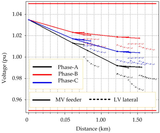
Figure 11.
Voltage profile for the simulated system at rated conditions.
5.2. Voltage Sensitivity Analysis for Cooperative Control
When a lateral leader “m” is not able to solve the overvoltage problem depending on its lateral PV systems, it activates the cooperative control and seeks other leaders’ support (one at a time). The effect of different leaders on the voltage of the lateral “m” determines the order by which they are called to support the lateral leader “m”. This section studies the voltage sensitivity to change in reactive power by different leaders to define the leaders’ order for each leader seeking support. To do so, the modified IEEE 13-bus system shown in Figure 10 was used with PV systems rated to the loads level. In this subsection, loads were operating at unity power factor to avoid reactive power flow due to loading. The following procedure was followed:
- For once, all the PV systems were running at unity power factor;
- A single PV system on lateral 1 has been modified to absorb reactive power (under-excited mode), while the rest of the PV systems were operating at unity power factor;
- The previous step for different laterals instead of lateral 1 is repeated;
- Voltage at different leaders was recorded for the previous steps.
Because the system has single-phase and three-phase PV systems, the absorbed Q was assumed the same value per phase. The percentage change in voltage at different leaders when absorbing reactive power by each lateral individually is calculated by (1):
where %∆Vij, Vi1, and Vij are the percentage change in voltage at leader “i” due to reactive power absorption on lateral “j”, the measured voltage at leader “i” when all PV systems operated at unity power factor, and the measured voltage at leader “i” due to reactive power absorption on lateral “j”, respectively.
The three-phase laterals have seen different voltage values for different phases because the system is unbalanced. Both minimum and maximum voltages for the three-phase laterals were used in the calculation. The calculated percentage change in voltage is given in Table 3 and Table 4. From the two tables, the following points can be derived:

Table 3.
Voltage sensitivity to change in reactive power (maximum change for three-phase laterals).

Table 4.
Voltage sensitivity to change in reactive power (minimum change for three-phase laterals).
- As expected, a lateral self-effect is the maximum. This emphasizes the role of the individual lateral-based control part;
- From Table 4, absorbing Q by single-phase laterals (6 to 11) may have a negative impact on the three-phase laterals due to the unbalance caused by this single-phase reactive power flow. Therefore, using single-phase leaders to support three-phase leaders will be avoided;
- Different leaders may have the same impact on another leader. Looking at the row corresponding to lateral 4 in Table 3, the effect of laterals 2, 3, and 5 is the same on lateral 4. In this case, the leaders are ordered according to their electrical distance from the main substation (i.e., lower loss first);
- Single-phase leaders of the same phase (e.g., 6 and 7) have a larger impact on each other but may have a negative impact on the other phases due to system unbalance.
From the previous points and the results provided in the tables, the first four supporting leaders can be sorted as given in Table 5 for different leaders that need help. When a certain leader requires help through the cooperative control, it calls its supporters according to the order in Table 5. For instance, if leader 1 requires support, it calls leader 5 first. In case leader 5 is not able to help leader 1, due to Q limitation, then the request goes to the next leader, which is leader 2 in this occasion.

Table 5.
Supporting leaders for every leader that needs help during the cooperative control.
5.3. Time Series Daily Simulation
The daily time series solution mode within the OpenDSS was used to simulate one day of operation with two minute’s step resulting in 720 test points. Different irradiance profiles [30] and load demand profiles [29] were used. The total load power and PV generated power are shown in Figure 12. As it can be seen, there are intervals where the PV generation exceeds the load, which resulted in an overvoltage at certain buses due to reverse power flow in the system.
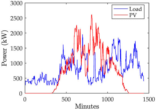
Figure 12.
Total load power and PV generated power.
The proposed controller has been applied to the system, and examples for three-phase and single-phase laterals exhibiting overvoltage are provided without and with the control applied in Figure 13, Figure 14, Figure 15 and Figure 16. The upper voltage limit used in this part of the study is 1.05 pu following ANSI C84.1 [8]. The maximum voltage before applying the control for phase-A, phase-B, and phase-C is 1.0854 pu, 1.0733 pu, and 1.0833 pu, respectively.
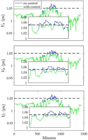
Figure 13.
Voltage on lateral 1 without and with control.
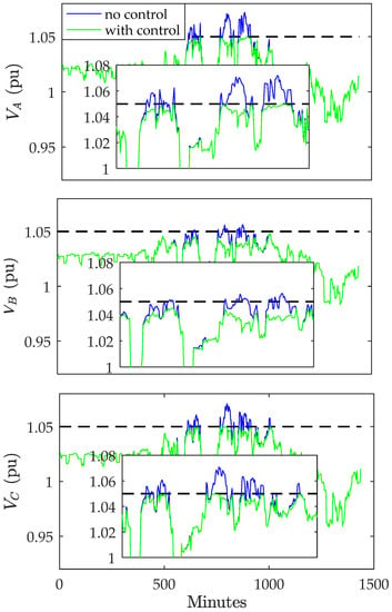
Figure 14.
Voltage on lateral 5 without and with control.
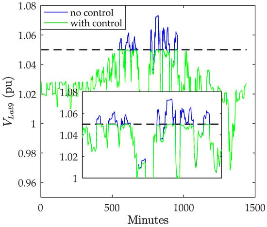
Figure 15.
Voltage on lateral 9 without and with control.
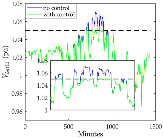
Figure 16.
Voltage on lateral 11 without and with control.
For a few test points, the individual controllers were not able to totally solve the overvoltage problem. Therefore, the cooperative control was activated. The performance of the individual and cooperative controllers is shown in Figure 17, Figure 18 and Figure 19. The voltage was slightly greater than the upper limit when operating the individual controllers, and the cooperative control allowed the voltage to satisfy the limit. The simulation results ensure the ability of the proposed control to mitigate the overvoltage problem at different operating conditions.
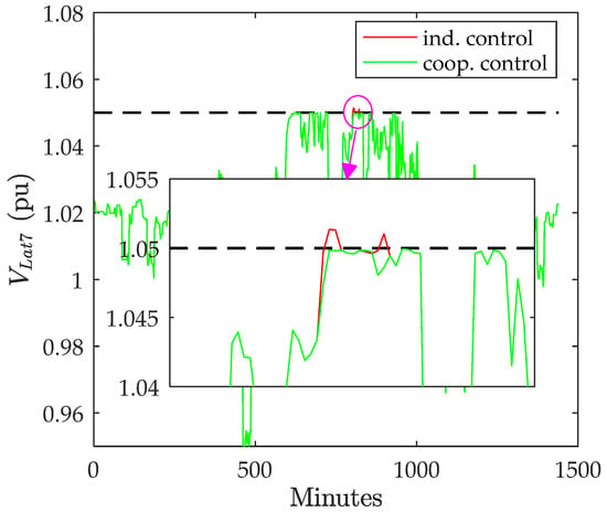
Figure 17.
Voltage on lateral 7 with individual control and cooperative control.
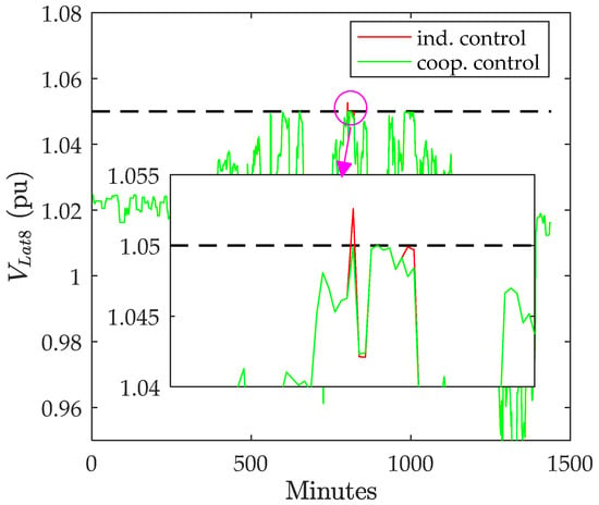
Figure 18.
Voltage on lateral 8 with individual control and cooperative control.
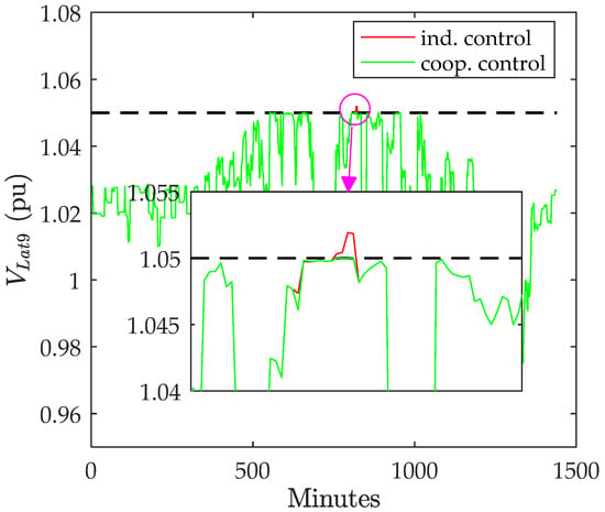
Figure 19.
Voltage on lateral 9 with individual control and cooperative control.
6. Conclusions
A volt/var controller has been presented in this paper to address voltage rise in the distribution grid caused by excess PV generation. The developed controller is proposed to operate at the lateral level coordinating the operation of different smart inverters along the lateral under different operating conditions. The controller relied on sequential activation of inverter control to minimize reactive power usage, resulting in lower active power loss due to reactive power flow. A cooperative control mechanism has been proposed to complement the individual laterals’ controllers. It only comes into play when one or more of the individual laterals’ controllers cannot resolve their overvoltage problems. A comparison study between the proposed controller and two other droop-based volt/var controllers emphasized that the proposed controller could solve the overvoltage problem using a lower amount of reactive power at different net PV generation levels. The proposed controller requires a simple low bandwidth communication platform between the lateral leading controller and the other inverters to dispatch the reactive power sequentially. However, it does not require defining a droop setting. On the other hand, the droop-based controllers operate locally without any communication but cannot ensure low reactive power requirement even if the droop setting was optimized as declared from the comparison study.
The IEEE 13-bus feeder was modified by adding 44 low-voltage buses and was simulated using the OpenDSS program to allow evaluation on an unbalanced system. Time series simulation solution mode was used to evaluate the controller performance at 720 operating points. The test points covered different loading and PV generation combinations. The individual laterals’ controllers succeeded to solve the overvoltage problem for most of the test points. When the individual control alone was unable to accomplish so, the cooperative control action made sure the overvoltage problem was solved. The evaluation at different load and PV generation levels ensures the successful coordination between the inverters at different operating conditions. The future work will target evaluation on other networks and the inclusion of other voltage control devices such as voltage regulators and FACTs. In addition, the design of the communication network is to be considered.
Author Contributions
Conceptualization, F.A. and I.P.; methodology, F.A. and O.C.; software, F.A.; validation, F.A.; formal analysis, F.A., I.P., O.C. and A.O.; investigation, F.A., A.F.Z. and G.T.; resources, G.T. I.P. and O.C.; writing—original draft preparation, F.A.; writing—review and editing, F.A., I.P. and O.C.; supervision, I.P., A.O. and A.F.Z.; project administration, I.P., G.T. and A.F.Z.; funding acquisition, I.P., O.C., A.F.Z. and G.T. All authors have read and agreed to the published version of the manuscript.
Funding
This research was funded by a Newton Fund Institutional Links grant number 623801791, under the Newton-Katip Çelebi Fund partnership. The grant was funded by the UK Department for Business, Energy and Industrial Strategy and TUBITAK grant number 120N996 and delivered by the British Council.
Data Availability Statement
The data presented in this study are available on request from the corresponding author. The data are not publicly available due to the project being ongoing.
Conflicts of Interest
The authors declare no conflict of interest.
Appendix A
The IEEE 13-bus feeder was modified by adding three- and single-phase laterals. The laterals’ data are provided in this appendix. Each lateral has one step-down transformer, four cable sections, four loads, and four PV systems. Table A1 provides the transformer and cable data. All three-phase PV systems are rated at 100 kW with inverter rating of 111 kVA. All single-phase laterals are rated at 30 kW with inverter rating of 33.5 kVA. The loads were assumed to operate at 0.9 lagging power factor and are rated as follows:
- All single-phase loads are rated at 30 kW;
- Laterals number 1, 2, and 3 have unbalanced loads for each loading point and are rated at (phase-A is 40 kW, phase-B is 30 kW, and phase-C is 30 kW);
- Laterals 4 and 5 are balanced and rated at 100 kW at each loading point.

Table A1.
Transformer and cable parameters.
Table A1.
Transformer and cable parameters.
| Element | Parameters |
|---|---|
| Single-phase transformer | 2.4/0.277 kV, 150 kVA, X = 2%, R = 1.1% |
| Three-phase transformer | 4.16/0.48 kV, 500 kVA, X = 2%, R = 1.1% |
| Single-phase cable section | 50 m, Z = 0.14 + j0.0357 Ω/km |
| Three-phase cable section | 50 m, Zs = 0.114 + j0.0359 Ω/km, Zm = 0.0228 + j0.0072 Ω/km |
References
- HM Government. Climate change Act 2008 (2050 Target Amendment) (No. SI 2019 No. 1056), UK Public General Acts. 2019. Available online: https://www.legislation.gov.uk/ukpga/2008/27/contents (accessed on 15 February 2023).
- Sambhi, S.; Sharma, H.; Bhadoria, V.; Kumar, P.; Chaurasia, R.; Fotis, G.; Vita, V. Technical and economic analysis of solar PV/diesel generator smart hybrid power plant using different battery storage technologies for SRM IST, Delhi-NCR Campus. Sustainability 2023, 15, 3666. [Google Scholar] [CrossRef]
- SolarPower Europe. Global Market Outlook for Solar Power 2022–2026. Available online: https://www.solarpowereurope.org/insights/market-outlooks/global-market-outlook-for-solar-power-2022 (accessed on 15 December 2022).
- Ismael, S.M.; Abdel Aleem, S.H.E.; Abdelaziz, A.Y.; Zobaa, A.F. State-of-the-art of hosting capacity in modern power systems with distributed generation. Renew. Energy 2019, 130, 1002–1020. [Google Scholar] [CrossRef]
- Uzum, B.; Onen, A.; Hasanien, H.M.; Muyeen, S.M. Rooftop solar PV penetration impacts on distribution network and further growth factors—A comprehensive review. Electronics 2021, 10, 55. [Google Scholar] [CrossRef]
- Vita, V.; Alimardan, T.; Ekonomou, L. The impact of distributed generation in the distribution networks’ voltage profile and energy losses. In Proceedings of the 2015 IEEE European Modelling Symposium (EMS), Madrid, Spain, 6–8 October 2015; pp. 260–265. [Google Scholar]
- Shayani, R.A.; de Oliveira, M.A.G. Photovoltaic generation penetration limits in radial distribution systems. IEEE Trans. Power Syst. 2011, 26, 1625–1631. [Google Scholar] [CrossRef]
- ANSI C84.1-2020; American National Standard for Electric Power Systems and Equipment Voltage Ratings (60 Hz). American National Standards Institute (ANSI): Washington, DC, USA, 2016.
- Sun, H.; Guo, Q.; Qi, J.; Ajjarapu, V.; Bravo, R.; Chow, J.; Li, Z.; Moghe, R.; Nasr-Azadani, E.; Tamrakar, U.; et al. Review of challenges and research opportunities for voltage control in smart grids. IEEE Trans. Power Syst. 2019, 34, 2790–2801. [Google Scholar] [CrossRef]
- Aboshady, F.M.; Pisica, I.; Ceylan, O.; Taylor, G.A.; Zobaa, A.F.; Ozdemir, A. Sequential volt/var controller for PV smart inverters in distribution systems. In Proceedings of the 2022 57th International Universities Power Engineering Conference (UPEC), Istanbul, Turkey, 30 August–2 September 2022; pp. 1–6. [Google Scholar]
- IEEE Std 1547-2018 (Revision of IEEE Std 1547-2003); IEEE Standards Coordinating Committee 21. IEEE Standard for Interconnection and Interoperability of Distributed Energy Resources with Associated Electric Power Systems Interfaces. IEEE: Piscataway, NZ, USA, 2018; pp. 1–138. [CrossRef]
- Almeida, D.; Pasupuleti, J.; Raveendran, S.K.; Basir Khan, M.R. Performance evaluation of solar PV inverter controls for overvoltage mitigation in MV distribution networks. Electronics 2021, 10, 1456. [Google Scholar] [CrossRef]
- Ghosh, S.; Rahman, S.; Pipattanasomporn, M. Distribution voltage regulation through active power curtailment with PV inverters and solar generation forecasts. IEEE Trans. Sustain. Energy 2017, 8, 13–22. [Google Scholar] [CrossRef]
- Rylander, M.; Li, H.; Smith, J.; Sunderman, W. Default volt-var inverter settings to improve distribution system performance. In Proceedings of the 2016 IEEE Power and Energy Society General Meeting (PESGM), Boston, MA, USA, 17–21 July 2016. [Google Scholar]
- Procopiou, A.T.; Ochoa, L.F. On the limitations of volt-var control in PV-rich residential LV networks: A UK case study. In Proceedings of the 2019 IEEE Milan PowerTech, Milan, Italy, 23–27 June 2019; pp. 1–6. [Google Scholar]
- Samadi, A.; Shayesteh, E.; Eriksson, R.; Rawn, B.; Söder, L. Multi-objective coordinated droop-based voltage regulation in distribution grids with PV systems. Renew. Energy 2014, 71, 315–323. [Google Scholar] [CrossRef]
- Samadi, A.; Eriksson, R.; Söder, L.; Rawn, B.G.; Boemer, J.C. Coordinated active power-dependent voltage regulation in distribution grids with PV systems. IEEE Trans. Power Deliv. 2014, 29, 1454–1464. [Google Scholar] [CrossRef]
- Kim, S.-B.; Song, S.-H. A hybrid reactive power control method of distributed generation to mitigate voltage rise in low-voltage grid. Energies 2020, 13, 2078. [Google Scholar] [CrossRef]
- Momeneh, A.; Castilla, M.; Miret, J.; Martí, P.; Velasco, M. Comparative study of reactive power control methods for photovoltaic inverters in low-voltage grids. IET Renew. Power Gener. 2016, 10, 310–318. [Google Scholar] [CrossRef]
- Ceylan, O.; Paudyal, S.; Pisica, I. Nodal sensitivity-based smart inverter control for voltage regulation in distribution feeder. IEEE J. Photovolt. 2021, 11, 1105–1113. [Google Scholar] [CrossRef]
- Wang, Y.; Tan, K.T.; Peng, X.Y.; So, P.L. Coordinated control of distributed energy-storage systems for voltage regulation in distribution networks. IEEE Trans. Power Deliv. 2016, 31, 1132–1141. [Google Scholar] [CrossRef]
- Mahdavi, S.; Panamtash, H.; Dimitrovski, A.; Zhou, Q. Predictive coordinated and cooperative voltage control for systems with high penetration of PV. IEEE Trans. Ind. Appl. 2021, 57, 2212–2222. [Google Scholar] [CrossRef]
- Zhang, C.; Xu, Y. Hierarchically-coordinated voltage/VAR control of distribution networks using PV inverters. IEEE Trans. Smart Grid 2020, 11, 2942–2953. [Google Scholar] [CrossRef]
- Xu, S.; Xue, Y.; Chang, L. Review of power system support functions for inverter-based distributed energy resources- standards, control algorithms, and trends. IEEE Open J. Power Electron. 2021, 2, 88–105. [Google Scholar] [CrossRef]
- Smith, J.W.; Sunderman, W.; Dugan, R.; Seal, B. Smart inverter volt/var control functions for high penetration of PV on distribution systems. In Proceedings of the 2011 IEEE/PES Power Systems Conference and Exposition, Phoenix, AZ, USA, 20–23 March 2011; pp. 1–6. [Google Scholar]
- Conti, S.; Gerco, A.M.; Raiti, S. Voltage sensitivity analysis in MV distribution networks. In Proceedings of the 6th WSEAS/IASME International Conference on Electric Power Systems, High Voltages, Electric Machines, Tenerife, Spain, 16–18 December 2006. [Google Scholar]
- EPRI. Open Distribution System Simulator, Sourceforge.Net. Available online: http://sourceforge.net/projects/electricdss/files/ (accessed on 1 December 2022).
- European Standard No. EN 50160; Power Quality Application Guide, Voltage Disturbances. European Committee for Electrotechnical Standardization (CENELEC): Brussels, Belgium, 2004.
- Test Feeder Working Group of the Distribution System Analysis Subcommittee. IEEE PES Test Feeder. Available online: https://cmte.ieee.org/pes-testfeeders/resources/ (accessed on 1 December 2022).
- Richardson, I.; Thomson, M. Integrated Domestic Electricity Demand and PV Micro-Generation Model, Loughborough University. Available online: https://hdl.handle.net/2134/7773 (accessed on 1 December 2022).
Disclaimer/Publisher’s Note: The statements, opinions and data contained in all publications are solely those of the individual author(s) and contributor(s) and not of MDPI and/or the editor(s). MDPI and/or the editor(s) disclaim responsibility for any injury to people or property resulting from any ideas, methods, instructions or products referred to in the content. |
© 2023 by the authors. Licensee MDPI, Basel, Switzerland. This article is an open access article distributed under the terms and conditions of the Creative Commons Attribution (CC BY) license (https://creativecommons.org/licenses/by/4.0/).