Article

An Experimental and Simulation Study for Comparison of the Sensitivity of Different Non-Destructive Capacitive Sensors in a Stratified Two-Phase Flow Regime

by
Mohammad Hossein Shahsavari
1,
Aryan Veisi
1,
Gholam Hossein Roshani
1,
Ehsan Eftekhari-Zadeh
2 and
Ehsan Nazemi
3,*
1
Electrical Engineering Department, Kermanshah University of Technology, Kermanshah 6715685420, Iran
2
Institute of Optics and Quantum Electronics, Abbe Center of Photonics, Friedrich Schiller University of Jena, 07743 Jena, Germany
3
Imec-Vision Laboratory, Department of Physics, University of Antwerp, 2610 Antwerp, Belgium
*
Author to whom correspondence should be addressed.
Electronics 2023, 12(6), 1284; https://doi.org/10.3390/electronics12061284
Submission received: 3 February 2023 / Revised: 1 March 2023 / Accepted: 3 March 2023 / Published: 8 March 2023
(This article belongs to the Special Issue Application of Artificial Neural Network in Non-destructive Testing)

Abstract

:
Measuring the volume fraction of each phase in multi-phase flows is an essential problem in petrochemical industries. One of the standard flow regimes is stratified two-phase flow, which occurs when two immiscible fluids are present in a pipeline. In this paper, we performed several experiments on vertical concave, horizontal concave, and double-ring sensors to benchmark obtained simulation results from modeling these sensors in stratified two-phase flow using COMSOL Multiphysics software. The simulation data was confirmed by experimental data. Due to the low number of data in the experimental method in order to extract more data, the mentioned software was used to extract more data and then compare the sensitivity of different directions of concave and double ring sensors. The simulation results show that the overall sensitivity of the concave is higher than the double-ring and the momentary sensitivity of the horizontal concave is higher in higher void fractions, and the vertical one has higher sensitivity in lower void fractions.

1. Introduction

Horizontal two-phase flow has been widely used in the petroleum industry. Flow measurement plays an important role in the oil industry; one of its most important applications can be mentioned in helping to manage reservoirs and designing piping systems [1,2]. Meanwhile, measuring a two-phase flow mixture is highly challenging because of the intrinsic complexity of how two phases are combined together. Over the years, different methods have been introduced, including acoustic emission, capacitance impedance, direct volume measurement, and radiation attenuation techniques. There are some benefits of using capacitance-based sensors for evaluating void fractions. They are relatively simple to design and to implement, non-intrusive to the flow, affordable, robust, and capable of directly detecting the flow rate of each component and void percentage without the need for separation [3]. In addition to measuring void fraction, capacitance-based sensors provide other facilities such as tomography hold-up detection and fluid velocity measurement [4,5,6,7,8,9,10]. A void fraction is defined as the volume of gas divided by the total volume of the pip [11]. To measure the void fraction, the capacitance-based sensor measures the capacitance that consists of the pipe, the materials inside it, and the electrodes. And obviously, capacitance is highly related to the material’s relative permittivity inside the pipe. Hence, when the amount of oil inside the pipe changes, relative permittivity varies accordingly, affecting the capacitance. Relative permittivity, is a measure of how well a material can store electrical energy when an electrical field is applied to it. It is calculated by comparing the energy stored in the dielectric material to the energy stored in a vacuum. Materials with higher relative permittivity have a greater capacity for storing electrical energy.
One of the critical parameters in capacitance-based sensors is the shape and configuration of electrodes [1]. Sami and his colleagues were among the first to evaluate different types of electrode shapes [12]. They divided capacitance sensors into six types of sensor configurations: parallel plates, concave plates, staggered concave plates, double helix, multiple helixes, and four concave plates, and evaluated them. They conducted experimental tests for two of the most important flow patterns: slug and stratified. The results showed that the four-concave plate has the highest sensitivity when the flow regime is known. Jaworek and Krupa [13] used an RF resonance circuit with a frequency of 80 MHz to calculate the void fraction. They used five different types of sensor architectures with the circuit and discovered that two half-cylinders (concave) have the highest sensitivity. In [7] Zhai Lusheng and his coworkers designed a 180-degree helix capacitance-based sensor using the finite element method in horizontal oil-water two-phase flow. Reis and Cunha [14] focused on stratified air/water two-phase flow. They tested concave ring and helical electrode shapes experimentally and the results showed that concave had the highest sensitivity and double-ring the lowest. In [15] Jiamin Ye and his coworkers presented a helical capacitive sensor to measure the void fraction in a small tube with gas-liquid two-phase flow. They used the finite element method to simulate and optimize the geometrical configuration of the electrodes. Tollefsen and Hammer [16] tried to optimize the accuracy of the sensitivity and flow regime independence of helical capacitance-based sensors. They modeled the sensor with the Finite Element Method (FEM). Their simulation was verified with different sensors and flow regime measurements and the maximum difference between simulated and measured results was 5%. As a result, the best overall accuracy they achieved was within ± 5%. Graets et al. [17] carried out extensive research on the helical electrode shape of capacitive sensing and emphasized the importance of shielding electrodes. They noticed how the thickness of the tube also affected the measurement results. Elkow and his coworkers [18] used helix and concave vertical flow sensors in a pipe to measure void fraction. The results showed that the shape of electrodes undeniably impacts the linearity of sensor response Zhao An et al. [6] used the finite element method to analyze and optimize a concave capacitance sensor in terms of sensitivity and holdup measurement characteristics in horizontal oil-water for different flow patterns. In [11], Salehi and colleagues introduced a new capacitance sensor design named TRFLC and the sensor with concave, and the results showed that TRFLC had better overall sensitivity than concave. In [19] Pal and Vasuki used a concave sensor for measuring void fraction from 0 to 100 percent in an experimental stratified two-phase flow setup. He used an LCR meter to measure the capacitance value of the sensor. In [20], Andreussi and his coworkers used capacitance-based sensors to measure void fraction in liquid slugs for air-water two-phase flow in a horizontal pipe. In [21], a new capacitance method for measuring film thickness was presented and found to be reliable and accurate through experimental testing. The method is capable of measuring local, time-varying, or steady-state film thickness and is described in detail in their paper. In [22], Huang and his coworkers carried out an experimental study on implementing a tomographic flow imaging system using capacitance-based sensors. They used an eight-blade concave sensor to construct the image of a pipe cross-section. In [23], Gammio and his coworkers used a capacitance-based sensor for tomographic imaging in a horizontal gas-oil two-phase flow. They made several flow patterns in a test loop and compared the produced images from tomography with observed results from a transparent section of the loop. In [24], a study on the measurement and analysis of water/oil multiphase flow using an Electrical Capacitance Tomography (ECT) sensor was conducted and its accuracy in terms of detecting the flow pattern of the water/oil multiphase flow was analyzed. A comparison of the results with existing methods was also presented. In [25], a capacitance-based sensor was used to measure the void fraction. They used five different electrode shapes and tried to optimize the sensitivity by changing the space between the ends of the electrodes. In [26], a capacitance signal analysis of two-phase flow in a small diameter tube was conducted by Caniere and his coworkers. An experimental setup was created to measure the capacitance signals and characterize the two-phase flow. It was found that the capacitance signals are a useful tool for analyzing two-phase flow in small diameter tubes. In our previous study [10], experiments have been conducted to validate simulations of air-water two-phase flow with an annular flow pattern. simulations were carried out using the finite element method in COMSOL Multiphysics. To measure void functions in various fluids, a concave capacitance-based sensor was designed and implemented. An Artificial Neural Network (ANN) was developed in MATLAB software. To provide sufficient data for Artificial Neural Networks (ANN) several modeling and analyzes were accomplished with different fluids (crude oil, diesel fuel, gasoline, and water).
In this paper, we compared the results of the experiment and simulation between concave and double-ring sensors. This study focuses on stratified air-water two-phase flow. The parameter that has been studied in this paper is the void fraction and the influence of electrode shape on the overall and momentary sensitivity of these two sensors. Meanwhile, the effect of orientation in concave has been also studied. To measure the capacitance an LCR meter has been used. This work’s main novelty lies in its investigation and comparison of the momentary sensitivity of a concave sensor in different orientations with a double-ring. To guarantee the precision of the simulations, comprehensive experimental tests have been conducted. The benchmarked simulations presented in this paper can serve as a reference for evaluating simulations performed with COMSOL Multiphysics in this particular field.

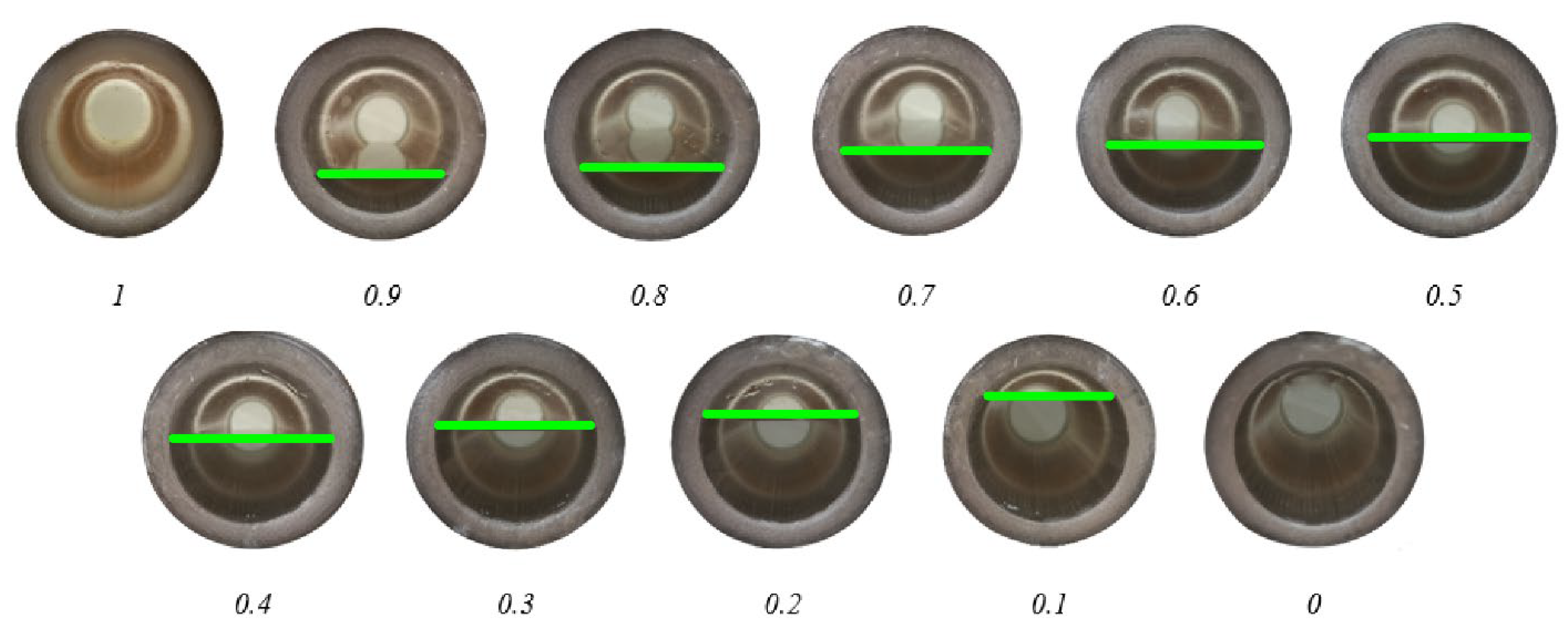
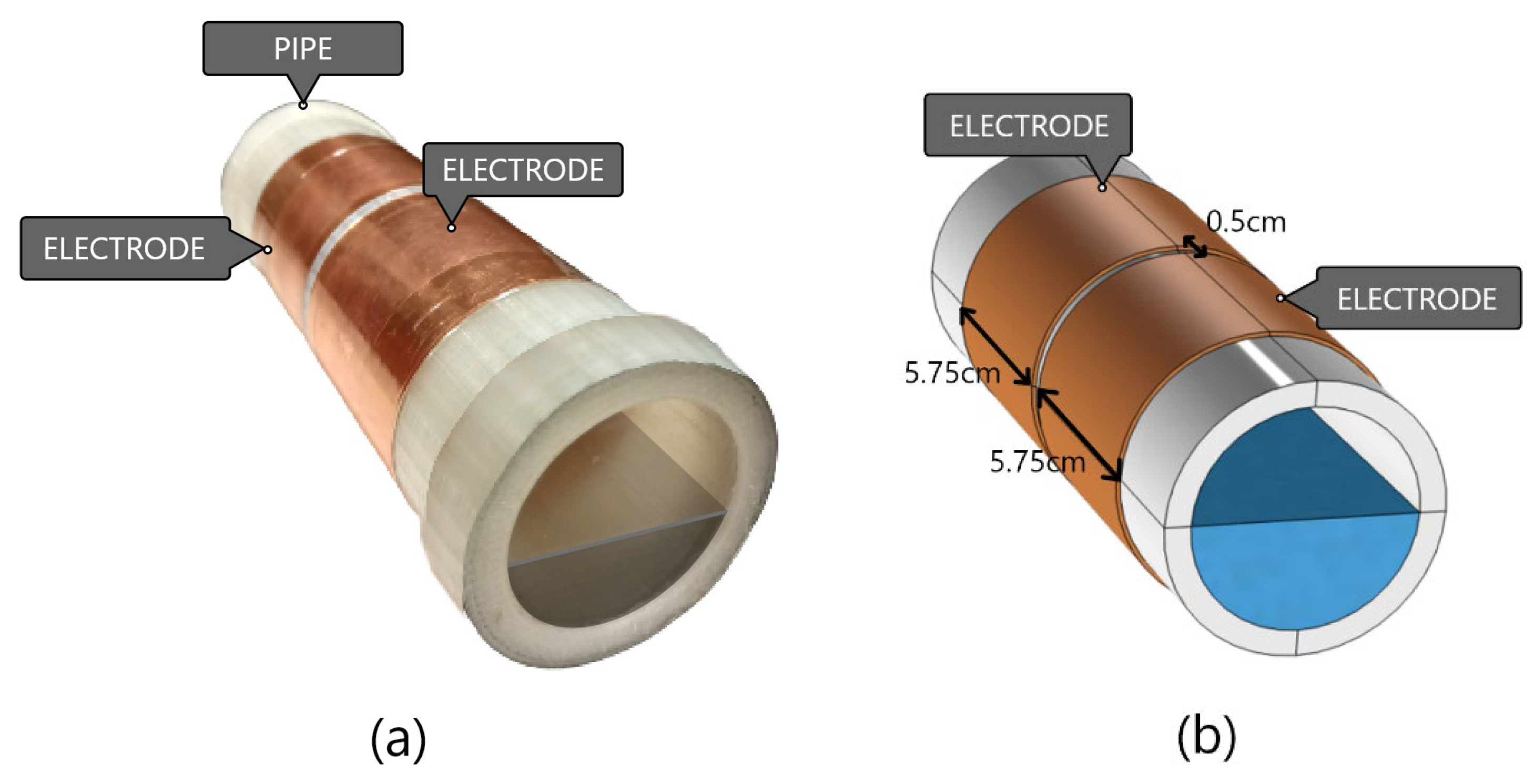
2. Experimental Setup

One of the important flow patterns that are common in industries is the stratified regime. In two-phase flow systems, when one fluid is heavier than another, it stays below, and this flow pattern is called stratified. This flow pattern happens in different fluid mixtures, such as liquid-gas or liquid-liquid.
We did experimental tests for concave and double-ring to verify simulations. Considering that this study focuses on comparing different sensors, we need to use a static setup to perform tests on different sensors. A pipe and copper electrodes were needed for the experimental implementation of sensors. To perform the test with sufficient accuracy, a PLA pipe with a specified Relative Permittivity of 3.3 was made using a 3D printer and transparent filament. The length, inner diameter, and the outer diameter of the printed pipe are 18 cm, 5.2 cm, and 6.4 cm, respectively. A thin sheet of copper is used for building electrodes. The electrodes are made by cutting this thin sheet into different shapes (concave and ring).
We tested and measured the capacitance of different void fractions (1, 0.9, 0.8, 0.7, 0.6, 0.5, 0.4, 0.3, 0.2, 0.1, 0) to evaluate the overall and momentary sensitivity of ring and concave sensors for each one of these sensors. Figure 1 shows different void fractions. To make different void fractions water was added to the amount of 10% of the pipe’s inner volume then capacity was measured. By repeating this process, different void fractions are made.

2.1. Double-Ring Configuration

Two ring electrodes with a length of 57.5 mm length are used for double-ring sensors made from 1 mm thin copper. The overall sensitivity of double ring increases as the distance decreases and for the sake of reproducibility and ease of production, 0.5 cm was chosen for the distance between electrodes [1]. The shape of the electrodes and pipe is presented in Figure 2.
As mentioned before the goal of this study is to evaluate overall and momentary sensitivities. We need C g which is the capacitance value when pipe is empty and C w which is capacitance value when pipe is filled with water for overall sensitivity and also capacity in different void fraction for momentary sensitivity. An LCR meter is used to evaluate the value of capacitance in different void fractions. The experimental setup is shown in Figure 3. Measured capacitance values for different void fractions are shown in Table 1.

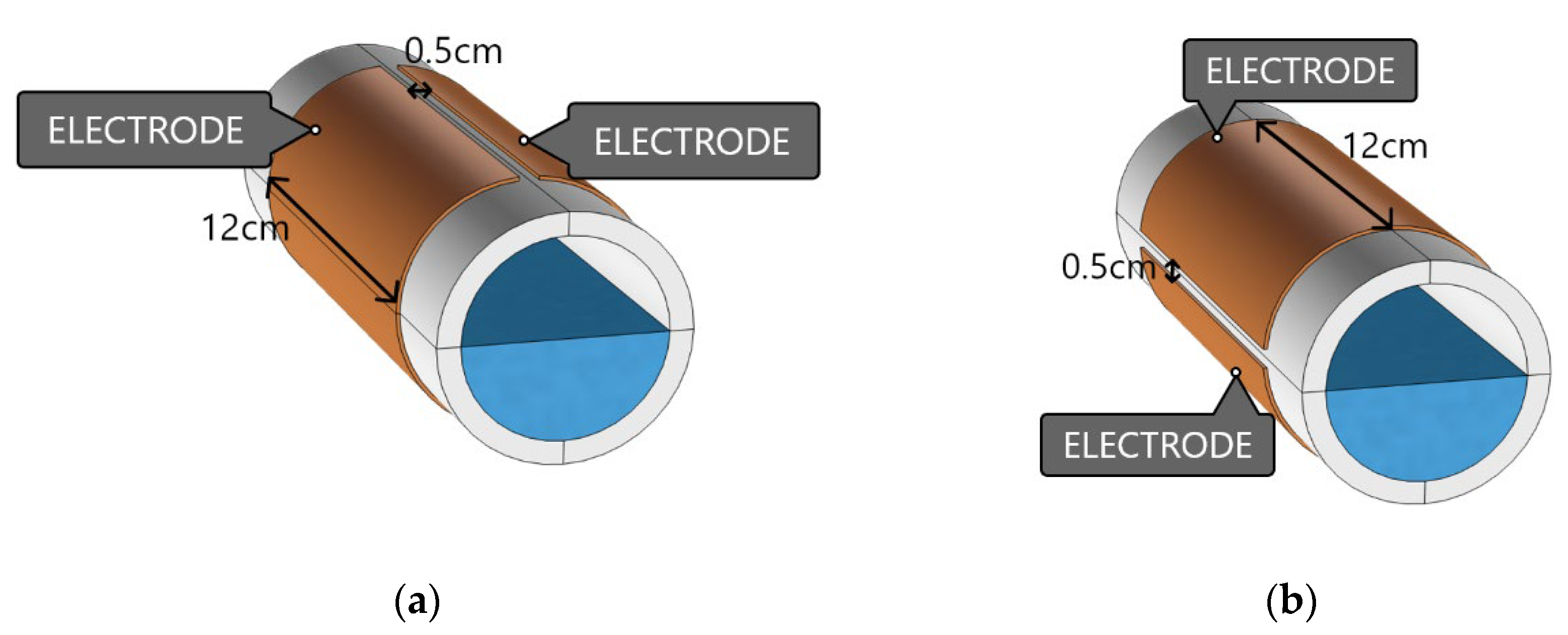
2.2. Concave Configuration

In order to implement the concave sensor configuration for electrodes, two rectangles with dimensions of 20 cm × 12 cm are made by cutting a thin sheet of copper. The electrodes are then mounted to the sides of the pipe as shown in Figure 4. An LCR meter was used to measure capacitances with this sensor in 11 void fractions. Measured values are presented in Table 2.

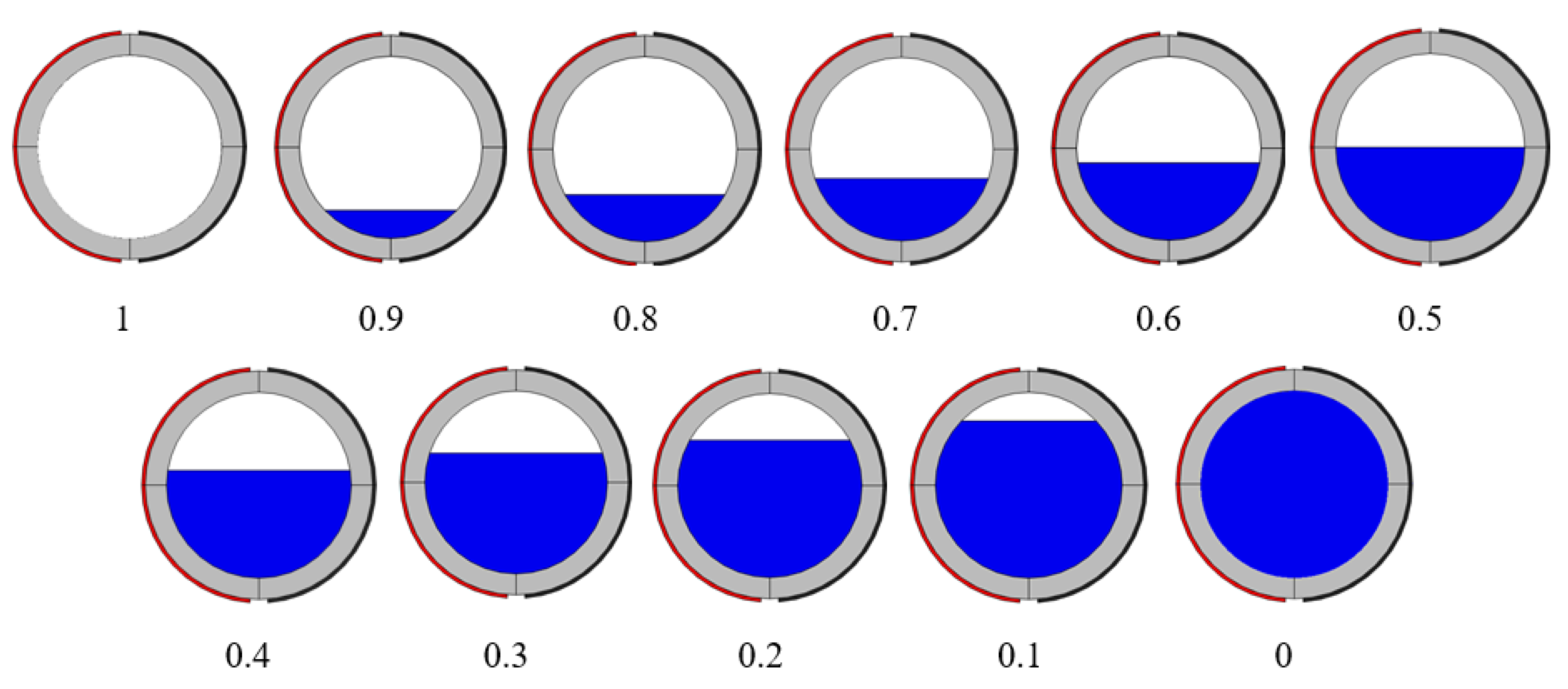
3. Numerical Simulations

In order to model experimental measurements, we have performed numerical simulations using COMSOL Multiphysics software 5.6. COMSOL is a globally used software that utilizes the finite element method for analysis and simulation. COMSOL provides an environment for designers and scientists to simulate and analysis in electrical, mechanical, fluid, acoustics, and chemical applications. Since strong fringe electric fields are observed around the capacitor plates, an air region was created in the simulation. This means the surrounding electrical fields can grow indefinitely, but they decrease as the distance from electrodes increases. That’s because the electrical field depends on the inverse of distance cubically so as distance increases, the electrical field will be negligible. As variables that effects the electrical field are constant over time the stationary study was used. For simulations, we have designed different void fractions with horizontal and vertical concaves, and also double-ring sensors. The geometry configurations in the simulation and other environmental parameters (Relative permittivity, inner diameter of pipe outer diameter of pipe, and size of electrodes) have been configured similarly to experimental measurements. Figure 5 shows different void fractions that are studied in simulations. As COMSOL employs the finite element method for reaching the most accurate results in all simulations, the mesh size has been set to finer and for the simulation, The mesh is defined as a network of elements that is used by COMSOL to simulate physical phenomena and solve it with the finite element method. By reducing the size of the element, the accuracy of the simulation increases. The mesh size of this simulation is set to finer, which for the maximum element size (limits how big each mesh element can be) is 0.7 cm, the minimum element size (limits how small each mesh element can be) is 0.03 cm, the maximum element growth rate (limits the size difference of two adjacent mesh elements) is 1.35, the curvature factor (Limits how big a mesh element can be along a curved boundary) is set to 0.3 and the resolution of narrow areas (controls the number of layers of mesh elements in narrow regions) is 0.85. A computer with an intel core-i5 2430 M CPU and 4 GB RAM was used.

3.1. Double-Ring Configuration

Figure 6 and Figure 7 show the design of the simulation that has been modeled and analyzed via COMSOL. The electric potential of the double-ring configuration was illustrated in Figure 6a,b shows the meshed model of the double-ring and Figure 7 shows the geometrical dimensions of the double-ring sensor. Maxwell capacitance was studied to evaluate the capacitance of this configuration. The results of the simulations have been shown in Table 3.

3.2. Concave Configuration

The COMSOL software has been also used to model the vertical and horizontal concaves, following the simulation of double-ring configuration. The simulated geometry of the concave sensor is shown in Figure 8. Also, Figure 9a,b represents the electric potential of these sensors, respectively. Figure 9c illustrates a meshed model of a concave sensor. The results of the finite element method are shown in Table 4.
To compare the results of experimental and simulation tests for each sensor, both results were normalized to unity and then were plotted and shown in Figure 10. Our findings show that simulations are following the same trends as experimental measurements and COMSOL Simulations are verified by testing the results against experimental data. This process ensures that the simulation is providing accurate and reliable results. The reproducibility of the experiment was checked by repeating the experiment multiple times.

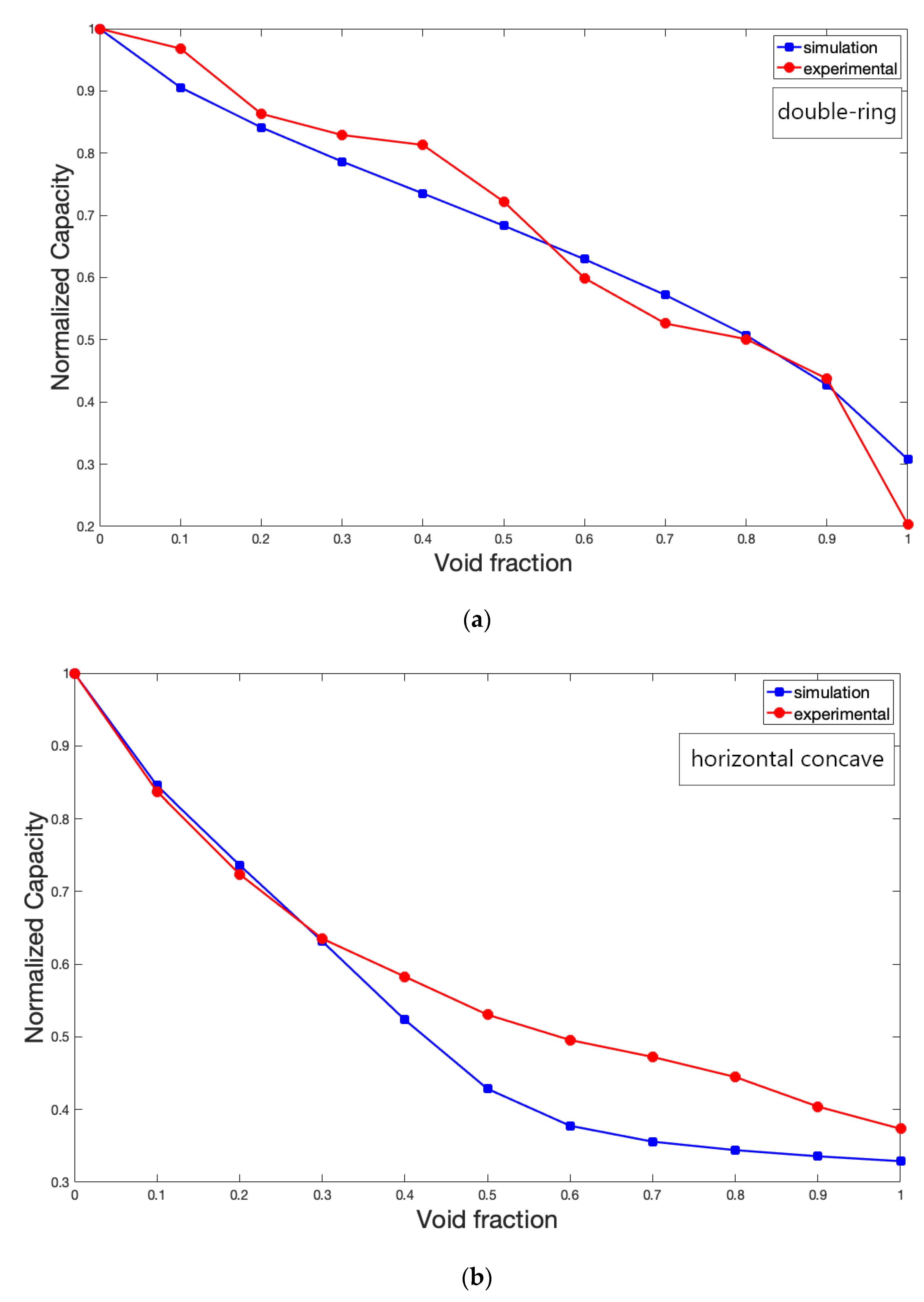
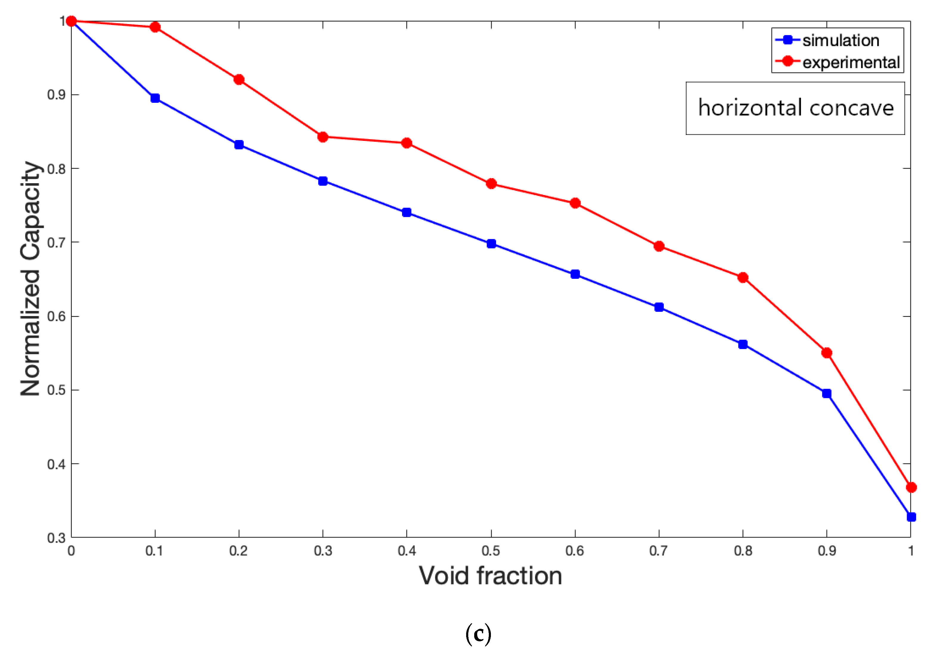
4. Results and Discussions

To compare double-ring with concave sensors, the overall sensitivity of these sensors has been evaluated by obtained simulation results.
The overall sensitivity is shown in Equation (1) [27]:
Overall   sensitivity = C W C G
The overall sensitivity of different sensors was 19.0, 19.0, and 13.3 for horizontal concave, vertical concave, and double ring sensor, respectively. In fact, overall sensitivity of concave sensor is higher than double-ring sensor. The more important parameter is the sensitivity of the sensor in different void fractions. In order to compare horizontal and vertical orientations, corresponding simulations have been accomplished for different void fractions (1, 0.95, 0.9, 0.85, 0.8, 0.75, 0.7, 0.65, 0.6, 0.55, 0.5, 0.45, 0.4, 0.35, 0.3, 0.25, 0.2, 0.15, 0.1, 0.05, 0). Momentary sensitivity is shown in Equation (2):
Momentary   sensitivity =   maximum   in   range minimum   in   range
The momentary sensitivity of different orientations of concave is shown in Figure 11. As shown in this figure, in higher void fractions (1–0.55) horizontal concave has higher sensitivity and vertical concave has higher sensitivity in lower void fractions.
The results show that the use of a horizontal concave sensor in industries where the void fraction of pipes is generally high is a good option and also the use of a vertical concave sensor in industries where the void fraction of pipes is generally low is recommended.
In different industries, the flow pattern is not constant and it is different in various conditions but in some applications, a stratified regime often happens. In chemical, petrochemical, and oil transportation industries stratified two-phase flow often occurs. In this paper, the application of double-ring and different orientations of concave was evaluated and it was found that in higher void fractions, the horizontal concave is a better choice and vertical concave is better for lower void fractions. Also, it should be noted that the simulated structure in this study was validated with several experiments. The experiments and consequently the simulations were performed in the static condition. The real working condition is dynamic but the reference points for training the flowmeter are fixed and it could be considered a static condition. These fixed points were used for training the flowmeter in order to determine void fractions with different orientations of concave and double-ring sensors. Generally, every flow meter in real condition needs several calibration points. These calibration points were obtained from a study like this. The inherent complexity of two-phase flows makes the selection of a suitable measurement system for void fraction calculation a difficult task. Many parameters such as cost and flow pattern influence the final choice. For this reason, there are various articles that have compared different sensors in different conditions, including flow patterns and different pipe orientations in order to get the best sensor for each of these conditions. In [11] Salehi and his coworkers proposed a new electrode geometry and compared it with others in stratified and annular two-phase flow. They found out the presented sensor was a better choice in terms of overall sensitivity. In [27], Roshani and his coworkers compared the gamma-ray attenuation sensor with capacitance-based sensors in terms of overall and momentary sensitivity. They found out the gamma-ray sensor had higher sensitivity in lower void fractions and capacitance-based sensors are more sensitive in lower void fractions. In this paper, the application of double-ring and different orientations of concave was evaluated. It was found that in higher void fractions, horizontal concave has higher sensitivity and vertical concave has higher sensitivity in lower void fractions. However, the sensitivity of these sensors could be improved by combining measurement systems with different types of radiation sources or different soft computing methods which were suggested for future works. Artificial Intelligence (AI) as well as Digital Signal Processing (DSP) is becoming increasingly common in the industrial sector. As it can be used to optimize products and reduce costs. A large and growing body of literature has investigated the use of AI in several industries [28,29,30,31]. Therefore, the use of AI can be a good alternative to be used for gaining more information from capacitance-based sensors [32].

5. Conclusions

In this paper, different orientations of concave and double-ring capacitance-based sensors were studied in stratified two-phase flow. This flow pattern is one of the most frequent patterns that happen in presence of two immiscible fluids in a pipeline. In order to benchmark simulation studies experimental setup and an LCR meter have been used to measure the capacity of different orientations of concave and double-ring sensors. Electrodes are made from a thin sheet of copper and pipe is produced using a 3D printer with an inner radius of 2.6 cm, an outer radius of 3.2 cm, a length of 18 cm, and relative permittivity of 3.3. The different orientations of the concave and double-ring sensors are modeled and analyzed by COMSOL Multiphasic software using the finite element method to compare their overall and momentary sensitivities. Simulations proved the higher overall sensitivity of the concave sensor compared to the double-ring sensor. Also, the simulations showed the different orientations of the concave sensors result in varied momentary sensitivity. According to our findings, sensors are more sensitive in lower void fractions with vertical concave configuration, and in higher void fractions with horizontal concave configuration.

Author Contributions

Conceptualization, M.H.S., A.V., G.H.R., E.E.-Z. and E.N.; methodology, M.H.S., A.V. and G.H.R.; software, M.H.S. and A.V.; data curation, A.V. and M.H.S.; writing—original draft preparation, M.H.S., A.V., E.E.-Z., G.H.R. and E.N.; writing—review and editing, M.H.S., A.V., E.E.-Z., G.H.R. and E.N.; investigation, M.H.S. and A.V.; visualization, M.H.S. and A.V.; supervision, G.H.R., E.N. and E.E.-Z.; resource, G.H.R.; validation, M.H.S. and A.V.; funding acquisition, G.H.R. and E.E.-Z.; All authors have read and agreed to the published version of the manuscript.

Funding

This research received no external funding.

Data Availability Statement

Not acceptable.

Conflicts of Interest

The authors declare no conflict of interest.

References

  1. Ahmed, H. Capacitance sensors for void-fraction measurements and flow-pattern identification in air–oil two-phase flow. IEEE Sens. J. 2006, 6, 1153–1163. [Google Scholar] [CrossRef]
  2. Steven, R.N. Wet gas metering with a horizontally mounted Venturi meter. Flow Meas. Instrum. 2002, 12, 361–372. [Google Scholar] [CrossRef]
  3. Yang, H.C.; Kim, D.K.; Kim, M.H. Void fraction measurement using impedance method. Flow Meas. Instrum. 2003, 14, 151–160. [Google Scholar] [CrossRef]
  4. Demori, M.; Ferrari, V.; Strazza, D.; Poesio, P. A capacitive sensor system for the analysis of two-phase flows of oil and conductive water. Sens. Actuators A Phys. 2010, 163, 172–179. [Google Scholar] [CrossRef]
  5. Strazza, D.; Demori, M.; Ferrari, V.; Poesio, P. Capacitance sensor for hold-up measurement in high-viscous-oil/conductive-water core-annular flows. Flow Meas. Instrum. 2011, 22, 360–369. [Google Scholar] [CrossRef]
  6. An, Z.; Ningde, J.; Lusheng, Z.; Zhongke, G. Liquid holdup measurement in horizontal oil–water two-phase flow by using concave capacitance sensor. Measurement 2014, 49, 153–163. [Google Scholar] [CrossRef]
  7. Ortiz, J.; Masek, V. Cyclonic capacitive sensor for multiphase composition measurement. Sens. Transducers 2015, 191, 1. [Google Scholar]
  8. Zhai, L.S.; Jin, N.D.; Gao, Z.K.; Zhao, A.; Zhu, L. Cross-correlation velocity measurement of horizontal oil–water two-phase flow by using parallel–wire capacitance probe. Exp. Therm. Fluid Sci. 2014, 53, 277–289. [Google Scholar] [CrossRef]
  9. Zhai, L.; Jin, N.; Gao, Z.; Wang, Z. Liquid holdup measurement with double helix capacitance sensor in horizontal oil–water two-phase flow pipes. Chin. J. Chem. Eng. 2015, 23, 268–275. [Google Scholar] [CrossRef]
  10. Veisi, A.; Shahsavari, M.H.; Roshani, G.H.; Eftekhari-Zadeh, E.; Nazemi, E. Experimental Study of Void Fraction Measurement Using a Capacitance-Based Sensor and ANN in Two-Phase Annular Regimes for Different Fluids. Axioms 2023, 12, 66. [Google Scholar] [CrossRef]
  11. Salehi, S.M.; Karimi, H.; Moosavi, R.; Dastranj, A.A. Different configurations of capacitance sensor for gas/oil two phase flow measurement: An experimental and numerical study. Exp. Therm. Fluid Sci. 2017, 82, 349–358. [Google Scholar] [CrossRef]
  12. Abouelwafa, M.S.; Kendall, E.J. The use of capacitance sensors for phase percentage determination in multiphase pipelines. IEEE Trans. Instrum. Meas. 1980, 29, 24–27. [Google Scholar] [CrossRef]
  13. Jaworek, A.; Krupa, A. Gas/liquid ratio measurements by rf resonance capacitance sensor. Sens. Actuators A: Phys. 2004, 113, 133–139. [Google Scholar] [CrossRef]
  14. Dos Reis, E.; da Silva Cunha, D. Experimental study on different configurations of capacitive sensors for measuring the volumetric concentration in two-phase flows. Flow Meas. Instrum. 2014, 37, 127–134. [Google Scholar] [CrossRef]
  15. Ye, J.; Peng, L.; Wang, W.; Zhou, W. Optimization of helical capacitance sensor for void fraction measurement of gas-liquidtwo-phase flow in a small diameter tube. IEEE Sens. J. 2011, 11, 2189–2196. [Google Scholar] [CrossRef]
  16. Tollefsen, J.; Hammer, E.A. Capacitance sensor design for reducing errors in phase concentration measurements. Flow Meas. Instrum. 1998, 9, 25–32. [Google Scholar] [CrossRef]
  17. Geraets, J.J.M.; Borst, J.C. A capacitance sensor for two-phase void fraction measurement and flow pattern identification. Int. J. Multip. Flow 1988, 14, 305–320. [Google Scholar] [CrossRef]
  18. Elkow, K.J.; Rezkallah, K.S. Void fraction measurements in gas-liquid flows using capacitance sensors. Meas. Sci. Technol. 1996, 7, 1153. [Google Scholar] [CrossRef]
  19. Pal, A.; Vasuki, B. Void fraction measurement using concave capacitor based sensor–Analytical and experimental evaluation. Measurement 2018, 124, 81–90. [Google Scholar] [CrossRef]
  20. Andreussi, P.; Bendiksen, K. An investigation of void fraction in liquid slugs for horizontal and inclined gas—Liquid pipe flow. Int. J. Multiph. Flow 1989, 15, 937–946. [Google Scholar] [CrossRef]
  21. Özgü, M.R.; Chen, J.C.; Eberhardt, N. A capacitance method for measurement of film thickness in two-phase flow. Rev. Sci. Instrum. 1973, 44, 1714–1716. [Google Scholar] [CrossRef]
  22. Huang, S.M.; Plaskowski, A.B.; Xie, C.G.; Beck, M.S. Tomographic imaging of two-component flow using capacitance sensors. J. Phys. E Sci. Instrum. 1989, 22, 173. [Google Scholar] [CrossRef]
  23. Gamio, J.C.; Castro, J.; Rivera, L.; Alamilla, J.; Garcia-Nocetti, F.; Aguilar, L. Visualisation of gas–oil two-phase flows in pressurised pipes using electrical capacitance tomography. Flow Meas. Instrum. 2005, 16, 129–134. [Google Scholar] [CrossRef]
  24. Kendoush, A.A.; Sarkis, Z.A. Improving the accuracy of the capacitance method for void fraction measurement. Exp. Therm. Fluid Sci. 1995, 11, 321–326. [Google Scholar] [CrossRef]
  25. Mohamad, E.J.; Rahim, R.A.; Rahiman, M.H.; Ameran, H.L.; Muji, S.Z.; Marwah, O.M. Measurement and analysis of water/oil multiphase flow using Electrical Capacitance Tomography sensor. Flow Meas. Instrum. 2016, 47, 62–70. [Google Scholar] [CrossRef]
  26. Canière, H.; T’Joen, C.; Willockx, A.; De Paepe, M. Capacitance signal analysis of horizontal two-phase flow in a small diameter tube. Exp. Therm. Fluid Sci. 2008, 32, 892–904. [Google Scholar] [CrossRef]
  27. Roshani, M.; Phan, G.T.; Nazemi, E.; Eftekhari-Zadeh, E.; Phan, N.H.; Corniani, E.; Tran, H.N.; Duong, V.H.; Roshani, G.H. Performance comparison of capacitance-based flowmeter with gamma-ray attenuation-based two-phase flowmeter for determining volume fractions in an annular flow regime’s components. Eur. Phys. J. Plus 2021, 136, 1–2. [Google Scholar] [CrossRef]
  28. Hosseini, S.; Taylan, O.; Abusurrah, M.; Akilan, T.; Nazemi, E.; Eftekhari-Zadeh, E.; Bano, F.; Roshani, G.H. Application of Wavelet Feature Extraction and Artificial Neural Networks for Improving the Performance of Gas–Liquid Two-Phase Flow Meters Used in Oil and Petrochemical Industries. Polymers 2021, 13, 3647. [Google Scholar] [CrossRef]
  29. Taylan, O.; Abusurrah, M.; Amiri, S.; Nazemi, E.; Eftekhari-Zadeh, E.; Roshani, G.H. Proposing an Intelligent Dual-Energy Radiation-Based System for Metering Scale Layer Thickness in Oil Pipelines Containing an Annular Regime of Three-Phase Flow. Mathematics 2021, 9, 2391. [Google Scholar] [CrossRef]
  30. Simorangkir, R.B.; Bayat-Makou, N.; Kishk, A.A.; Esselle, K.P. Advancements and artificial intelligence approaches in antennas for environmental sensing. In Artificial Intelligence and Data Science in Environmental Sensing; Academic Press: Cambridge, MA, USA, 2022; pp. 19–38. [Google Scholar]
  31. Afzal, M.U.; Hayat, T.; Esselle, K.P.; Mandal, K. All-metal wideband metasurface for near-field transformation of medium-to-high gain electromagnetic sources. Sci. Rep. 2021, 11, 9421. [Google Scholar]
  32. Iliyasu, A.M.; Fouladinia, F.; SSalama, A.; Roshani, G.H.; Hirota, K. Intelligent Measurement of Void Fractions in Homogeneous Regime of Two Phase Flows Independent of the Liquid Phase Density Changes. Fractal Fract. 2023, 7, 179. [Google Scholar] [CrossRef]
Figure 1. Different water levels in the cross-section of the pipe to create different void fractions in the experimental experiment where the water level is highlighted with a green line on each image of different void fractions.
Electronics 12 01284 g001
Figure 2. Double-ring sensor, (a) Experimental, (b) Simulation where the blue color represents the water level, the gray color represents the pipe, and the red color represents the electrodes.
Electronics 12 01284 g002
Figure 3. Measuring the capacitance value of pipe with a horizontal concave sensor using an LCR meter.
Electronics 12 01284 g003
Figure 4. Diagram of a concave sensor for two-phase stratified flow, (a) Horizontal orientation, (b) Vertical orientation.
Electronics 12 01284 g004
Figure 5. Different water levels in the cross-section of the pipe for a different void fraction in COMSOL, where the blue color represents the water level, the gray color represents the pipe, and the red and black colors represent the electrodes.
Electronics 12 01284 g005
Figure 6. Double-ring sensor in stratified two-phase flow simulation (a) schematic of electric potential where red color represents high potential and blue color represents low potential, (b) meshed model.
Electronics 12 01284 g006
Figure 7. Dimensions of the double-ring designed by COMSOL simulation where the blue color represents the water level, the gray color represents the pipe, and the red and black colors represent the electrodes.
Electronics 12 01284 g007
Figure 8. Simulated concave sensor along with its dimensions with the stratified two-phase flow where the blue color represents water level, the gray color represents the of the pipe, and the red and black colors represent the electrodes.
Electronics 12 01284 g008
Figure 9. Electrical potential of the concave sensor in (a) Horizontal orientation, (b) Vertical orientation and (c) Meshed model of the horizontal concave sensor.
Electronics 12 01284 g009
Figure 10. (a) Comparing the results of simulation and experiments for double-ring configuration, (b) Comparing the results of simulation and experiments for vertical concave configuration, (c) Comparing the results of simulation and experiments for horizontal concave configuration.
Electronics 12 01284 g010aElectronics 12 01284 g010b
Figure 11. Comparing horizontal concave, vertical concave, and double-ring sensors in different ranges.
Electronics 12 01284 g011
Table 1. Measured capacity values in different void fractions for double ring sensor.
Experimental Results
Void FractionDouble-Ring (pF)
18.91
0.919.23
0.822.04
0.723.15
0.626.35
0.531.76
0.435.74
0.336.41
0.237.97
0.142.55
043.93
Table 2. Measured capacitance values at different void fractions for the concave sensor.
Experimental Results
Void FractionHorizontal Concave (pF)Vertical Concave (pF)
125.3225.72
0.937.9127.84
0.844.9230.66
0.747.8532.54
0.651.8734.12
0.553.6536.54
0.457.4340.11
0.358.0243.73
0.263.3149.81
0.168.2757.62
068.8468.84
Table 3. Measured capacitance values in different void fractions for double-ring sensor using COMSOL.
Simulation Results
Void FractionDouble Ring (pF)
15.94
0.98.25
0.89.79
0.711.04
0.612.15
0.513.19
0.414.19
0.315.18
0.216.24
0.117.48
019.30
Table 4. Measured capacitance values in different void fractions for concave sensor in simulations.
Simulation Results
Void FractionHorizontal Concave (pF)Vertical Concave (pF)
19.309.31
0.914.059.50
0.815.939.74
0.717.3410.07
0.618.6010.69
0.519.7812.14
0.420.9714.83
0.322.2017.86
0.223.5820.85
0.125.3623.95
028.3428.34
Disclaimer/Publisher’s Note: The statements, opinions and data contained in all publications are solely those of the individual author(s) and contributor(s) and not of MDPI and/or the editor(s). MDPI and/or the editor(s) disclaim responsibility for any injury to people or property resulting from any ideas, methods, instructions or products referred to in the content.

