Article

Localization of Wireless Capsule Endoscopes Using the Receiver Selection Algorithm and a Modified Capsule Antenna

by
Paweł Oleksy
* and
Łukasz Januszkiewicz
Institute of Electronics, Lodz University of Technology, Politechniki 10 Street, 93-590 Lodz, Poland
*
Author to whom correspondence should be addressed.
Electronics 2023, 12(4), 784; https://doi.org/10.3390/electronics12040784
Submission received: 30 November 2022 / Revised: 31 January 2023 / Accepted: 2 February 2023 / Published: 4 February 2023

Abstract

:
Wireless capsule endoscopes capture and transmit images of the human gastrointestinal tract for use in medical diagnosis. The localization of the capsule makes it possible to precisely identify areas with lesions detected during the examination. The antenna is an important element of the endoscopic capsule that is used for the transmission of the signal containing the recorded image of the inside of the digestive system. Antenna parameters influence also the performance of algorithms that are locating capsule endoscopes based on the analysis of the received signal. The zig-zag conformal antenna for the endoscope capsule is presented in this paper. It was examined both in simulation and tissue simulant liquid. It is then applied to an improved localization system that is based on phase difference analysis of received signals. In this new approach, the algorithm selects five external receivers from the predefined set and uses an adaptive estimation of human body model permittivity. The localization algorithm was verified with computer simulations. Remcom XFdtd software and both simplified and heterogeneous human body models were applied in simulations. The technique which uses automatic selection of the external receiver together with proposed antenna enhanced localization accuracy by about 15% compared with the previous version of this algorithm.

1. Introduction

Gastroscopy and colonoscopy are the two basic and most commonly performed endoscopic examinations of the digestive tract. Gastroscopy is used to evaluate the oesophagus, stomach, and duodenum. It is a basic examination in the diagnosis of cancers of these organs or ulcer diseases. A colonoscopy is an endoscopic examination of the large intestine, just like gastroscopy, used in the diagnosis of cancer and other intestinal diseases. These diagnostics can also be performed with the use of wireless endoscopes fabricated in the form of a small capsule equipped with a camera and a transmitter used to transmit the recorded image. This type of device helps to detect pathological changes along the entire length of the digestive system in a comfortable and non-invasive way for the patient. The duration of such an examination is approximately 8 hours. Very often, the use of this type of device in medical diagnostics requires that the image recorded by the camera be supplemented with information about its exact location. This is very important, especially when further treatment of the patient requires surgery or precise application of pharmacological agents. It is important not only to know where the capsule is along the digestive tract, but also where is located in three dimensions to corelate the images captured by camera with results of other medical diagnostics techniques (e.g., magnetic resonance imaging (MRI)) [1].
Many methods of locating capsule endoscopes have been developed so far. We can distinguish methods based on the analysis of the electromagnetic field [2,3,4,5], image processing [6], or tracking methods based on information from inertial sensors [7].
The localization methods of capsule endoscopes can be also classified according to the position of the object in relation to the body. There are methods that allow to determine the position of the endoscope along the digestive tract and those that identify the position in a three-dimensional coordinate system. The first group of methods is based on tracking displacements and orientation of the capsule. In the case of the second group, methods based on the analysis of the electromagnetic field are most often used. For example, solutions using information on the distribution of magnetic field strength provide results with an error not exceeding 20 mm [2,4], which is comparable to the size of an endoscope. Other methods (including the one described in this article) use algorithms based on parameters of the received signal, such as received power level, signal propagation time, or received signal phase difference. Due to the complexity of wireless propagation channel inside the human body, it is necessary to use a model that takes into account the electrical parameters of individual tissues.
All these methods have certain limitations that significantly affect the accuracy of the positioning. In the case of algorithms based on the analysis of the electromagnetic field, the parameters of the received signal are affected by multipath propagation inside the human body. As a result, it is not possible to unambiguously map the measured values of received power or phase shift to the distance of the transmitter from the individual receiving nodes located on the patient’s body. The use of accurate body models made, for example, with the use of an Nuclear Magnetic Resonance (NMR) scanner allows to significantly improve the accuracy of localization; however, it is a costly and time-consuming solution. In the case of methods based on image analysis or movement tracking with the use of inertial sensors, the obtained results may be subject to error resulting from the patient’s movement or the variable velocity of the capsule’s displacement in individual sections of the digestive system.
Methods that are based on the analysis of the signal phase shift are sensitive to the location of the receivers on the patient’s body. The algorithm proposed by the authors in the previous paper can use information about the signal phase from any number of external receivers [8]. However, as the research has shown, a large number of receivers (in practice more than 5) causes an increase in the positioning error and extends the estimation time of a single capsule position. Therefore, a method was developed in which the algorithm automatically selects only five receivers from a set of nine receivers placed on the patient’s body based on the received power level.
Many methods of capsule endoscope localization proposed so far use information on the parameters of the wireless signal emitted the by endoscope by its antenna [3,5,8]. Moreover, wireless capsules have limited power budget which is mainly determined by limited space which can be used by capsule battery. For this reason, there is a need to reduce transmitter power as much as possible. Data transmission performance may be improved by introducing optimal channel coding [9] as well as improving antenna parameters. The latter can be obtained by minimizing return loss which may be caused by antenna detuning effect in different body tissues. For this reason, next to the camera and algorithms for the automatic detection of lesions, the capsule antenna is a key element of endoscopic capsules. There are two basic limitations that must be considered when designing a capsule antenna. The first is the size of the capsule which varies depending on the manufacturer. The shape is similar to a cylinder with a height varying from 24.5 to 31 mm and a diameter from 10.8 to 11.4 mm [10]. The second limitation is the frequency of the signal that can be used in implantable medical devices. In the case of endoscope capsules, it is Medical Implant Communication System (MICS) band with a frequency range from 401 MHz to 406 MHz [11]. A human body is a heterogenous environment that affects antenna impedance matching and received power level in the wireless link. During the medical examination, the capsule goes through entire digestive tract and is exposed to the environment with variable electrical properties. Therefore, the antenna should have wide bandwidth so that the detuning effect in tissues with different electric properties does not deteriorate the transmission at the particular frequency.
Due to the limited size, relatively low operating frequency (the wavelength is greater than the capsule size) and dynamic electrical environment, designing small antenna that can be built into the capsules is a challenging task. Designing antenna for lower band (MICS) is more complex as it must match to relatively long wave. The wavelength λd in dielectric of relative permittivity εr is shorter than in the wavelength in free space λc, according to Equation (1).
λ d = λ c ε r
The values of relative permittivity εr within the body differ in the range from 40 to 60 [12]. For frequency of 405 MHz and the average permittivity of human tissues that equals 50, the wavelength λd is approximately 105 mm. Assuming that the largest dimension of capsule is 26 mm, the entire antenna cannot be larger than ¼ of wavelength. Many types of endoscopic antennas have been presented in the literature [13,14,15,16,17,18,19,20,21,22,23]. From the construction point of view and possible location of the antenna in the capsule, they can be divided into those that have a spatial structure that occupies significant volume of the capsule [13,14,15], and those that can be placed on the surface of the capsule [16,17,18,19,20,21,22,23]. The first type has a limited applicability due to the fact that they take up space needed for other electronic capsule components such as camera battery, processor, transceiver parts, or LED. The second type is more popular due to its conformal structure. In such antennas, a conductive element is usually fabricated of copper placed on a flexible dielectric substrate, due to which it can be adapted to the size and shape of the capsule.
Capsule antennas can be also classified by their operation frequency band. Typical endoscopes antennas operate in one MICS band [13]. There are also some antennas designed for industrial, scientific, and medical bands ((ISM) 433 MHz, 915 MHz, and 2.45 MHz, respectively) [18,20] or medical telemetry service (608–614 MHz) [23]. Such an approach is usually determined by the evolution of endoscopes which must perform many tasks simultaneously providing a high data rate which requires higher bands. Even if the capsule antenna supports higher bands, in many cases it should be compatible with MICS.
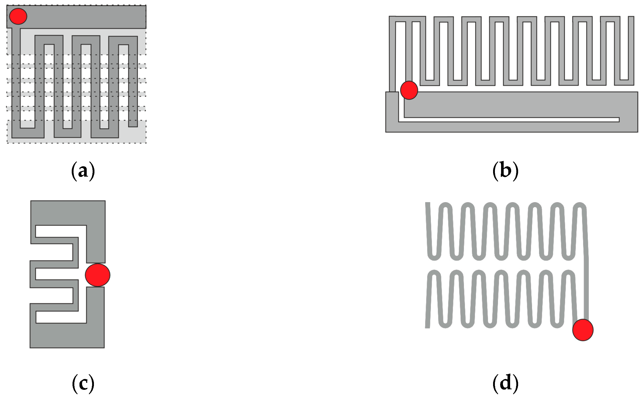
Among many modifications of the helical geometry of an antenna radiator, meander shape was often adapted for the antennas that operate inside human body. 
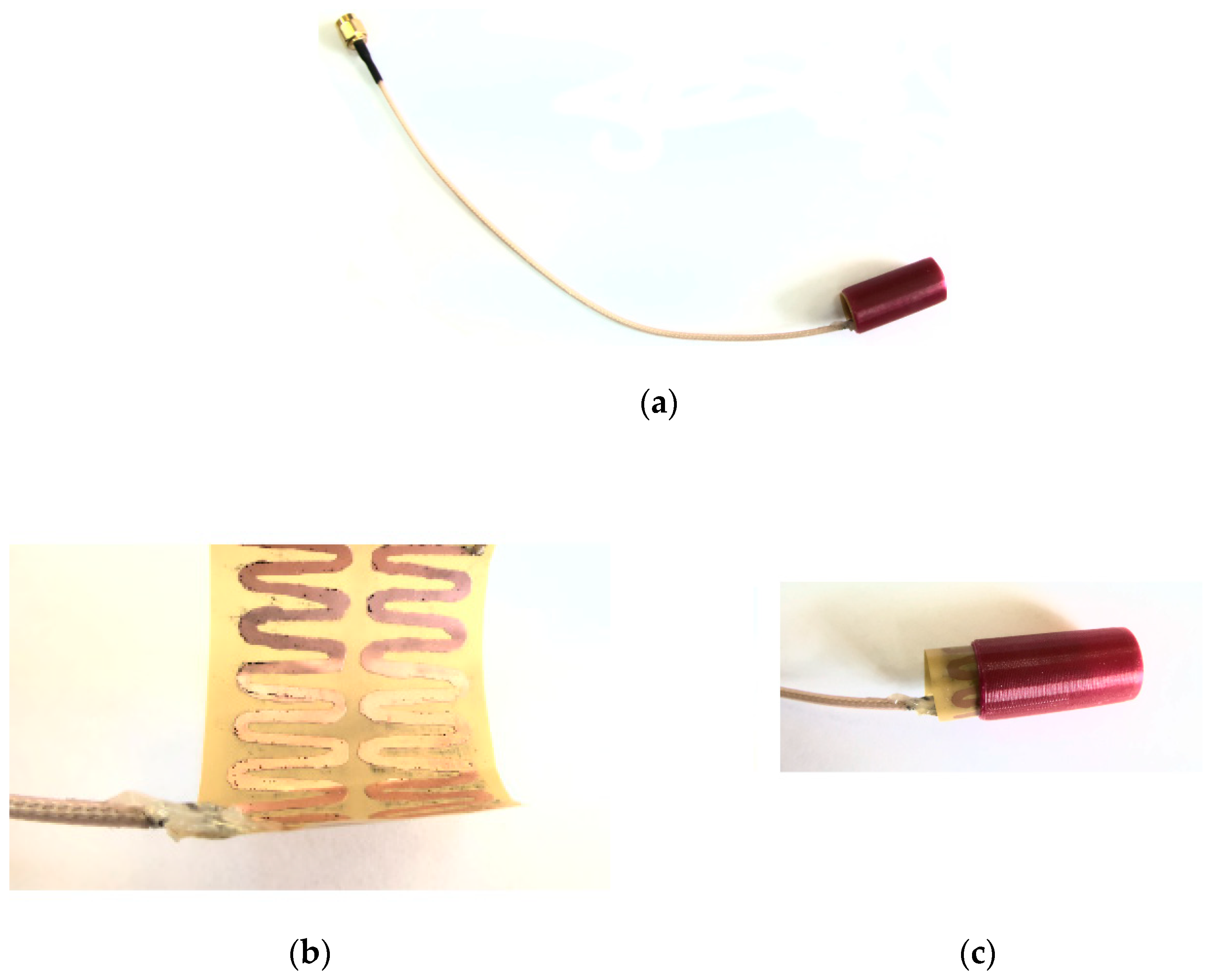
Figure 1 presents examples of capsule antenna radiators (metallic parts). The first one (Figure 1a) [14] was designed for much shorter waves as it operates in 2.40 GHz band. It has a spatial structure (2 layers separated by dielectric) and was fabricated on Rogers 3010 non-flexible substrate that makes this design difficult to fit into endoscopic capsule. The feeding point is attached between radiators that are on opposite sides of the dielectric substrate. Compared with other antennas presented in Figure 1 it is not matched to MICS band in which the wireless capsule operates. The next two antennas (Figure 1b [19] and Figure 1c [21]) have conformal structures and were fabricated on a flexible laminate. The antenna presented in Figure 1b consists of meander in the form of “F” structure and slotted L-shaped ground plane. The feeding point is attached between “F” structure and ground plane. Due to the high sensitivity of the antenna bandwidth to open slots, antenna detuning may be caused by both manufacturing flaws and variations in the tissues surrounding the antenna. The antenna shown in Figure 1c was designed in the form of a closed-loop meander that is a loop dipole with reduced size thanks to the meander section. It is however sensitive to the surrounding material since it changes significant impedance matching for different implantation depths [21].
Since the meander structure was successfully used to form different radiators of endoscopic capsule antenna, the radiator of the antenna utilized this shape. Figure 1d presents the antenna proposed in this study which was optimized to reduce attenuation between capsule end receivers located on the patient body. This antenna consists of two meanders and has open-loop structure. The shape of meanders were optimized and were designed to be manufactured on flexible laminate.
In this article, the research on a folded zig-zag antenna for a wireless capsule is presented which allows to reduce attenuation of signal between the endoscope and external antennas by 9 dB. The proposed antenna utilizes to meander shape, can be fabricated on flexible laminate and then wrapped around the capsule under its shell. The impedance matching of the antenna prototype was measured in a simplified cylindrical human body model filled with tissue simulant liquid. The designed antenna was verified with computer simulations together with the model of the endoscopic capsule. The model of the capsule contains different elements such as a battery or camera. The design of the improved endoscopic antenna is presented together with impedance matching and an analysis of transmitted power efficiency. Simulations were carried out in different tissues which may surround the capsule during movement inside the digestive tract. The antenna together with the capsule model were applied to the improved version of the localization algorithm.
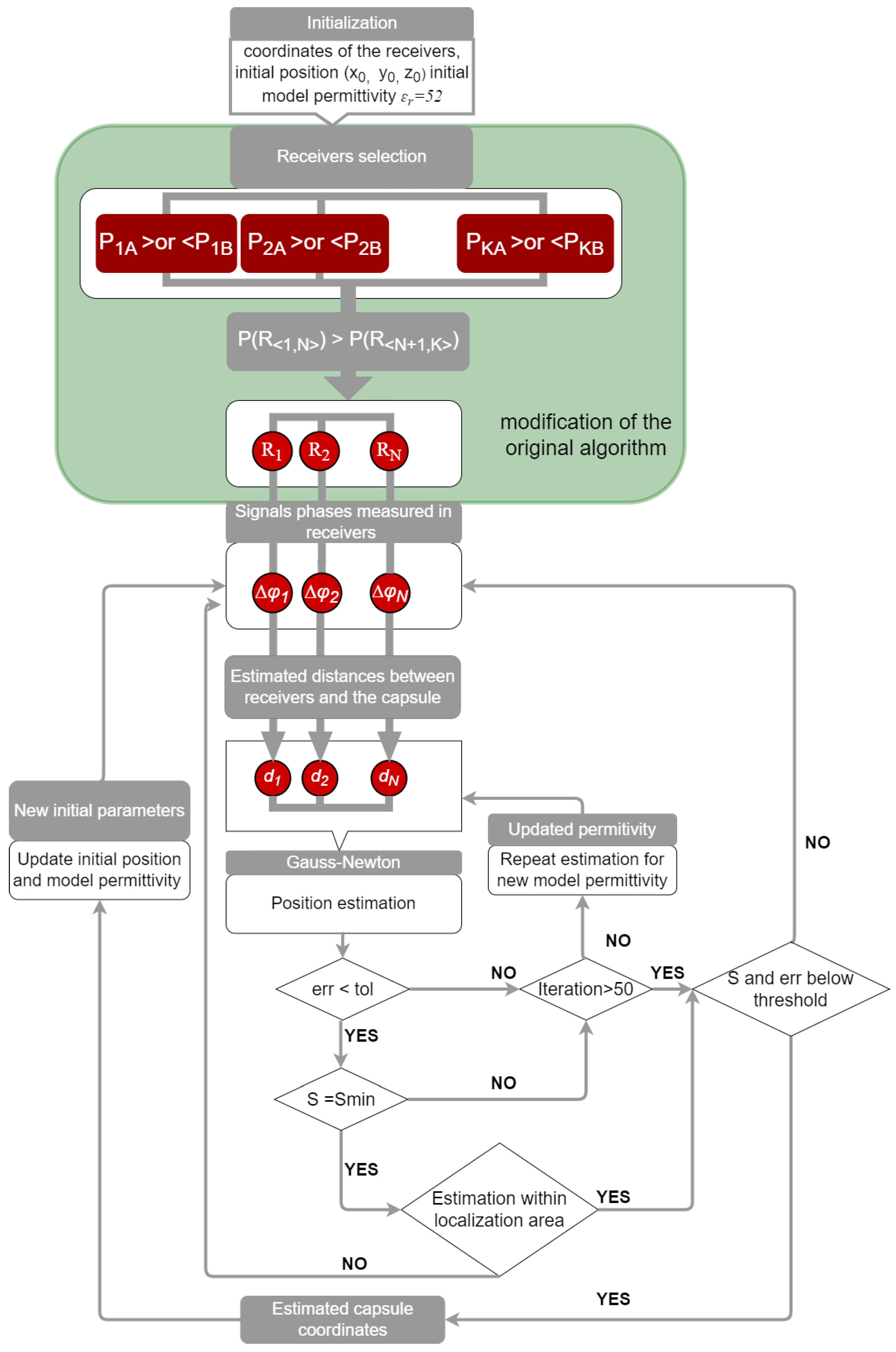
In this paper we present also the novel version of localization algorithm that automatically selects receivers from a redundant set. In our previous study, it was observed that the number of external receivers as well as their position on the patient’s body has a significant impact on the accuracy of endoscope localization. For better localization accuracy this algorithm has now the possibility to select the receivers that provide data. Below, the impact of the proposed antenna with capsule model and the improved localization algorithm on localization error are investigated.

2. Materials and Methods

2.1. Endoscopic Antenna Design

The human body consists of many tissues which have different electrical properties. This is a big challenge for the designer of an implantable antenna, especially when it changes position inside the body as is the case of a capsule endoscope. The design of wireless networks which are used in the human body (Wireless Body Area Networks (WBANs)) is usually carried out with the use of a dedicated software that allows for simulation of electromagnetic wave propagation in such a complex environment. In the case of the human body, it is possible to use accurate models that represent its shape and dimensions, as well as its internal structure and the electric properties of tissues [24]. Another approach is to use simplified models which represent only a small region of body and allow to shorten the calculation time. Since they represent the averaged properties of tissues, they are less susceptible to the variations in the anatomy of the individual human subject.
The main component of the endoscope capsule is a camera equipped with an optical dome. It is connected to an electronic circuit which is responsible for image acquisition and transmission. The transmitter is directly connected to the antenna to optimize the size of the capsule. The antenna can be fabricated on the internal surface of the capsule shell using the physical vapor deposition (PVD) process. It can also be etched on flexible laminate which can be then rolled up and placed around internal capsule elements. Due to its thin structure, such antennas allow to save space inside the capsule which can be utilized for the battery needed to power the electronic component.
To design the antenna for the capsule endoscope, the Remcom XFdtd program that implements finite difference time domain was used [25]. In the primary research we used a simplified model of tissues in the form of homogeneous cylinder of permittivity εr = 57 and conductivity of σ = 0.76. Such a reduced model could be used here because the antenna input impedance mainly depends on the antenna structure and the materials that are located in its proximity. The height of the tissue simulant model is V = 250 mm and its radius is R = 100 mm. The antenna model in tissue simulant material is presented in Figure 2.
The proposed antenna consists of two conducting meanders that are shaped in the form of a “crown”. It was designed for the best impedance marching to 50 Ω in the MICS band. We assumed that the impedance bandwidth of the antenna is the frequency range where S11 ≤ −10 dB, which is a commonly used approach [14,16,17]. The antenna radiator is fabricated of copper of 45 μm thickness, which makes it possible to etch it into a flexible laminate. Thanks to this, it can be easily adapted to the shape of the endoscope capsule and save the volume of the capsule. Antenna layout and its spatial view is presented in Figure 3. It was designed to not excide the typical size of an endoscope capsule which is similar to a cylinder with a height of 26 mm and a diameter of 11 mm. Therefore, the total height of the antenna is H = 20 mm and the diameter is d = 10 mm.
The capsule shell and its internal components can affect antenna performance, especially its impedance matching. To analyze their impact on antenna performance, the capsule model presented in Figure 4 was prepared. It consists of a thin shell and electronic components fabricated of alumina, an optical dome fabricated of glass, a battery fabricated of perfect conductor, a camera fabricated of silicon, and a printed circuit board fabricated of FR4 laminate. The electrical properties of the used materials are presented in Table 1. The whole capsule was enclosed in an alumina shell of 0.3 mm thickness, length equal to 26 mm, and radius equal to 11 mm diameter.
All the simulations in this paper were performed for the endoscopic antenna together with the capsule model presented on Figure 4. Figure 5 presents antenna impedance matching for the case in which it is located inside tissue simulant material. In Figure 6 the antenna radiation pattern for the frequency of 403.MHz is presented. Since the antenna remains inside a cylinder fabricated of conducting material (tissue simulant) the maximum gain is −32.2 dBi.

2.2. Localization Algorithm with Receiver Antenna Selection

The localization algorithm uses the principle of detecting the phase differences of the signal transmitted from endoscope to the receiving antennas located on the surface of the body. To minimize the effect of wave reflections (that disturb signal phase shift), particularly at the interface between the body and the air, the receiving antennas were placed directly on the surface of the body model. The dipoles were used as receiving antennas. They were matched to 403 MHz for on-body position by changing their length. In the initial study presented in our former paper [26], the localization algorithm used values of signal phase shift obtained from four receivers. Their positions were adjusted to minimize the distance estimation error obtained with the algorithm. This was accomplished using computer simulations and the NMR Hershey model of the entire body that is available in XFdtd Remcom program. The transmitting antenna (endoscope) was placed inside the heterogeneous model of the human body, while the receiving antennas were placed in different places on the body surface. The distances between the transmitter and the individual receiving antennas were determined, assuming the average permittivity of the medium εr = 20. This value was assigned experimentally to minimize the error of the estimated distance for the antenna located in the position that was closest to the capsule. The best accuracy was obtained for receiving antennas placed on the torso, near the front of the body. Further research showed that the position estimation is burdened with a significant error when the capsule is outside the area limited by external receivers. This is mainly the reason for the two following factors: The first of them is the attenuation introduced by the human body and the second is the influence of many tissues through which the wave propagates, slowing down, reflecting, or deflecting the signal. It was also noticed that the addition of one more external receiver (as presented in Figure 7a) allows to reduce the location error by a few millimeters. Additionally, the effect of the number of receivers on the localization accuracy was investigated. The number of external receivers arranged in matrix were changed from five to nine. It was noticed that having a larger number of receivers does not improve the accuracy of the location and even in some cases provides worse results. It was additionally observed that if the value of the received signal power in individual receivers is lower, worse location accuracy is achieved by the phase difference obtained with those receivers. To improve the localization precision, the algorithm with adaptive receiver selection based on the received signal power level was proposed. The antenna configuration is presented in Figure 7b. There are K = 9 receivers available; however, taking into account the fact that the endoscopic capsule changes its orientation while moving in the digestive tract, it was decided to introduce additional receivers using horizontal dipoles, as also presented in Figure 7.
The capsule endoscope localization algorithm developed in previous research enables automatic adjustment of the electric permittivity for a given location [8]. In the proposed approach, the geometrical coordinates of the capsule in three-dimensional space are determined using the Phase Difference of Arrival (PdoA) method. Therefore, the information on the phase difference of signals with frequencies f1 and f2 available in individual receivers coordinates with external receivers and the initial value of the permittivity of the model is required. In a previous study it was observed that the number of external receivers as well as its localization in relation to patient body has significant impact on localization accuracy. Moreover, when the received signal is significantly attenuated due to properties of body tissues and distance between capsule and external antenna, the signal phase is affected by significant error. Therefore, in the algorithm based on the measurement of the phase difference of the received signal, it is also important to ensure the appropriate level of the received signal power. Due to the limited power budget of the wireless endoscope and the fact that the human body absorbs the energy of electromagnetic waves, a new approach was proposed. External receivers are automatically selected from the predefined set based on the power level of the received signal. This technique included in the localization algorithm presented in Figure 8 is marked in the green frame.
In the first stage, the algorithm compares power for vertical (PkA) and horizontal (PkB) receivers and chooses the one for which the received power is greater. Then from the obtained set of K = 9 receivers, N = 5 is selected for which the received power is the highest according to Formula (2) (R1 denotes receiver with the highest received power, RK denotes receiver with the lowest received power). Thus, when the capsule position is estimated, those receivers are selected for which the received power level is the highest, and the signal phase information cannot be used simultaneously from Ak and Bk antennas in one step of the algorithm.
P R 1 , N > P R N + 1 , K
In the next step, the distances dn from the endoscopic capsule are determined based on the phase difference according to Formula (3) [8].
d n = c 2 * π * ε r * Δ φ n Δ f
where dn is the distance of the capsule from the N-th antenna placed on the human body;
c is the velocity of an electromagnetic wave in a vacuum;
εr is the model permittivity;
Δφn is the phase difference of the received signals sent on two frequencies f1 and f2;
Δf is the difference between frequency f1 and f2.
Permittivity is the main feature which describes the adopted body model. It has the same permittivity value towards each receiving antenna, but this value may be different for successive positions of the capsule. In a real environment, the average permeability values differ, therefore the distances determined in this step are only approximated.
Then, the Gauss–Newton algorithm is used to determine the geometrical coordinates of the capsule. The goal of the algorithm is to find such coordinates that minimize the function S provided by Formula (4) [8].
S = n = 1 N r n 2
where N is the number of receiving antennas placed on the body,
r n = d n x u n 2 + y v n 2 + z w n 2
where x, y, z are the estimated capsule coordinates;
un, vn, wn are the coordinates of antennas placed on the body.
For each estimated capsule position, an error function provided by Formula (5) [8], is evaluated. It is the difference in the distance between the last two iterations of the Gauss–Newton algorithm. It was assumed that in case of the proposed conformal antenna for the algorithm to converge, the value of erri function should met condition expressed by Formula (7) [8]. For the initial value of permittivity εr = 52, this condition is very often not met; therefore, in the next step of the algorithm the permittivity value is sought that allows it to be achieved. The next step aimed at improving the accuracy of the algorithm is the minimization of the S function according to Formula (6) [8], by changing the permeability value in the range for which the convergence of the method was achieved in the previous step. Permittivity of a model εr can have a value in the range from 1 to 60.
e r r i = x i x i 1 2 + y i y i 1 2 + z i z i 1 2
where erri is the error of the i-th iteration of the least squares method;
xi, yi, zi are the capsule coordinates estimated in the i-th iteration, where 0 < i < 50.
S m i n = m i n ε r   ϵ   1 , 60 | S ( ε r ) |
The last step of the algorithm is the classification of the obtained results. At the first stage it is checked if the achieved estimation is in the localization area defined by the dimensions and shape of the adopted body model, then it is evaluated if values of the S and erri functions are in accordance with Formulas (7) and (8) [8]. This is directly connected with the convergence of the Gauss–Newton method. If the measured phase is significantly affected due to signal attenuation, its deflection and reflection or other propagation phenomena the convergence condition cannot be met.
S ε r ,   , Δ φ N * r n 2
e r r i ε r , Δ φ < 0.04 * H  
where H is the high of the conformal antenna presented on Figure 3.
When the algorithm has access to new values of received signal phases, the capsule position can be updated. The initial position and permittivity are updated using the information obtained for the last successful estimation. Moreover, initial model permittivity is updated with the value used for the last successful position estimation. This allows to decrease the number of algorithm iterations and shorten computation time.

3. Results

The proposed antenna at the first stage was verified using computer simulations. It was designed assuming that it will be sourounded by a tissue simulant material. The parameters of tissues which directly surround the capsule in the digestive tract were choosen for simplified models to validate antenna performance and to check its impedance matching in the digestive tract. To investigate its performance in the proximity of different tissues a series of simulations were performed for tissue simulant material of diferent electric properties. They were selected to correspond to the parameters of the tissues that build the organs through which the endoscopic capsule moves. Parameters of selected materials are presented in Table 2. At the first stage of the research the average model for human body with permittivity εr = 57 and conductivity S = 0.76 S/m was applied. This is a commonly used approach in the design of wireless systems operating in the area of the human body [24]. During simulation in Remcom XFdtd software the antenna was implanted in the middle of the cylindrical model as presented in Figure 2. In the simulation the Gaussian-shaped signal was used as an excitation.
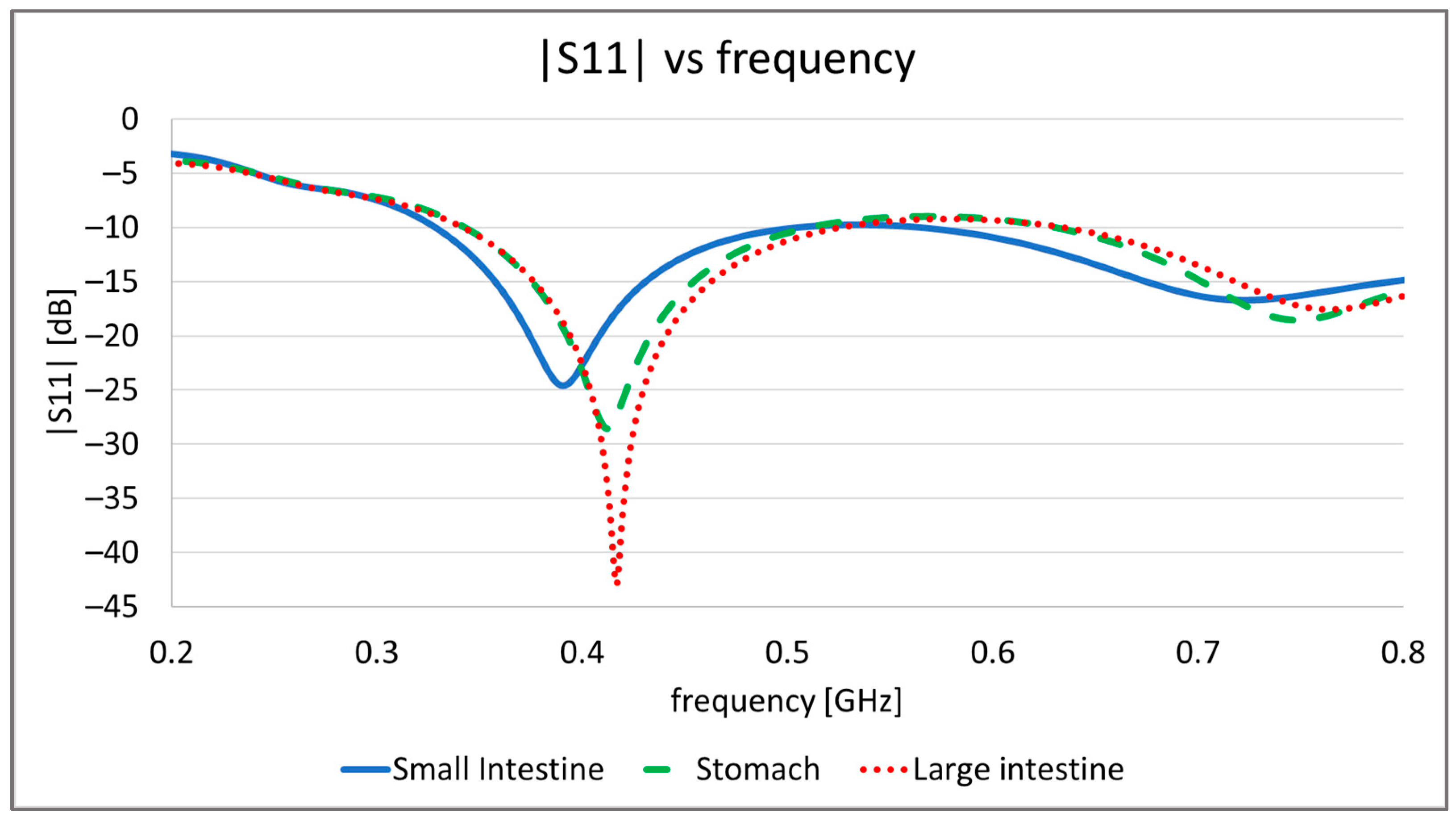
In Figure 9 the simulation results of antenna impedance matching to 50 Ω are presented. Simulations with an average body model show that in such an environment, the proposed antenna has a wide bandwidth from 200 MHz to 1.1 GHz. In the case of antennas that are implanted and can move inside body it can suffer from impedance detuning. Simulations performed with models that had properties of different tissues confirm this. This can be seen especially for the small intestine. Taking into account results for all examined tissues, the effective bandwidth for the proposed antenna remains in the range from 380 MHz to 480 MHz. This means that it can be applied for the MICS band.
Depending on the position of the capsule, the human body can significantly attenuate the wave transmitted from the endoscope. The appropriate power level is also important for the proper phase detection in the individual external receivers located on the patient’s body. Therefore, the value of power received in external receivers for the helical antenna and the proposed conformal antenna was compared. For this purpose, simulations were carried out for four simplified models of the human body with different electrical properties. The models were selected to correspond with the tissues in which the endoscopic capsule can be found: stomach, large intestine, and small intestine. Moreover, the averaged model was used due to the fact that the power of the received signal is affected by all tissues of the human body through which the radio wave propagates. Parameters of individual models are presented in the 
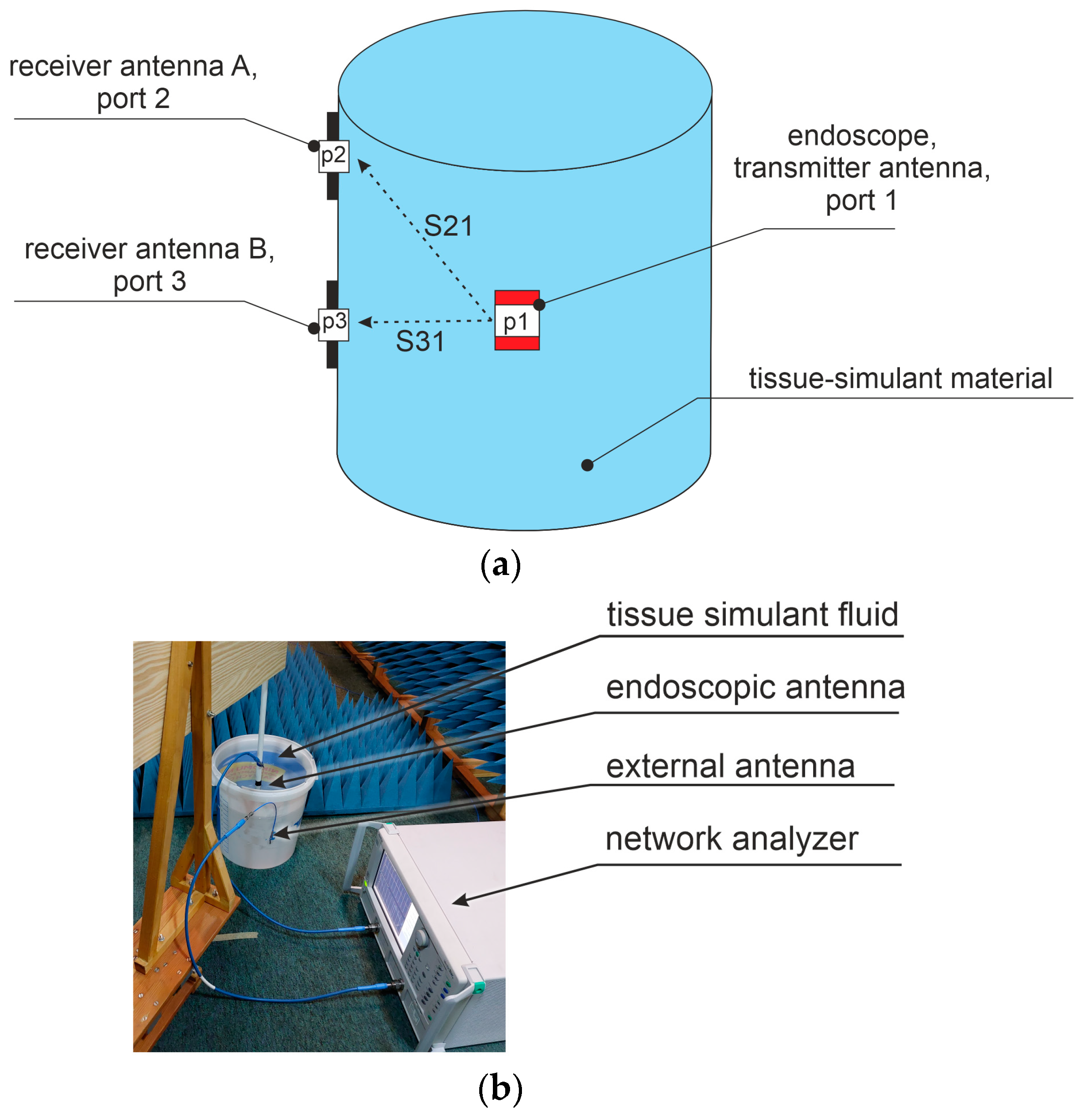
Table 2. The antenna verification setup is presented in Figure 10. External antennas A and B were placed next to the model fabricated in the form of a cylinder. The capsule was placed in the middle of the model. The attenuation of signal between antennas was simulated as the system loss, using scattering matrix parameters that represent coupling between antenna ports. Table 3 presents the values of S21 and S31 achieved respectively for receiver A with port 2 and receiver B with port 3. The proposed conformal antenna provides significant improvement compared with the helical antenna. The difference varies from around 9 dB to 7dB. This improvement is very important for the adaptive receiver selection algorithm as the received power level is used to decide which receivers should be chosen.
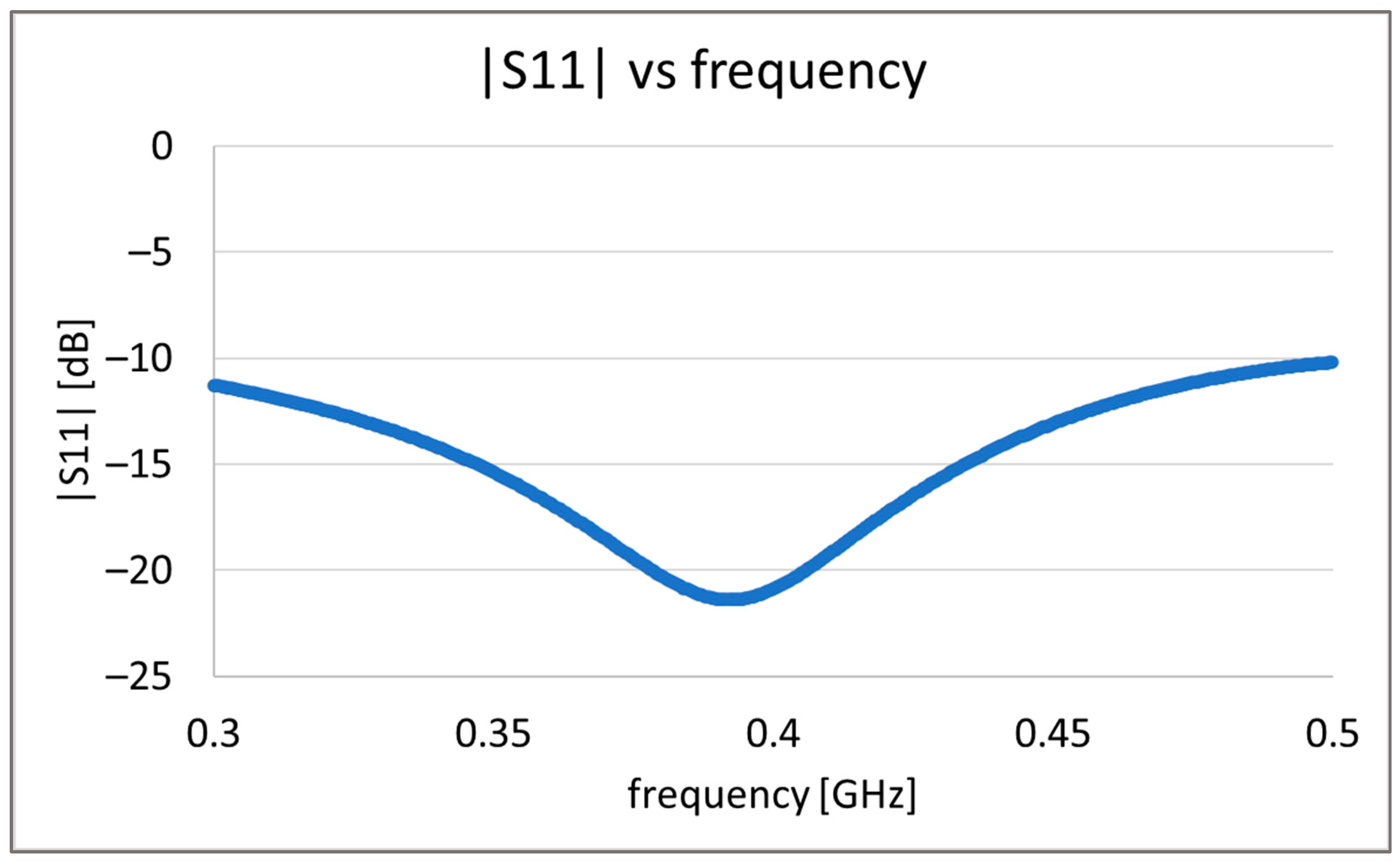
Due to technological limitation we decided to fabricate the antenna prototype replacing capsule materials with PLA material. For this reason simulation with PLA material was performed. The results obtained from simulations show that material of capsule shell mainly impacts antenna impedance matching. Slightly increasing the antenna height by 3 mm, it is possible to achieve impedance matching for 400 MHz frequency as presented in Figure 11. The antenna adopted to be placed in PLA capsule shell is within the dimensions typical for commonly used capsules. The antenna radiator is fabricated of Pyralux 25-micron thick Polymide laminate covered with 45 um copper. Its structure presented in Figure 12b was printed on laminate and then etched using sodium persulfate and soldered to coaxial cable. The antenna radiator was rolled up and inserted between two 3D-printed elements as presented on Figure 12c.
At the next stage, the proposed antenna was validated by measurements in the simplified human body phantom. The body model was fabricated of a thin-walled plastic vessel filled with tissue simulant liquid. It had the same dimensions as the one shown in the Figure 2 used in the simulations. In the proposed experiment it was assumed that the fluid should have parameters similar to average values of the human body. For this a solution of water, sugar, and salt was prepared. The proportions of this solution were defined experimentally in previous research [8] and has the following values: 1 L of water, 350 g of sugar, and 15 g of salt. Depending on the source of the water used for the solution its electrical parameters may change the properties of the achieved liquid. For this reason, the values of permittivity and conductivity were measured with the DiLine measurement setup procedure by Index Sar Company [27] presented on Figure 13. This uses a vector network analyzer connected to the TEM line filled with prepared liquid to measure the electric length and loss of line. At the temperature of 23 °C and at 400 MHz permittivity was equal to εr = 57, and the conductivity was σ = 0.75 S/m. In our research we used the Anritsu MS 4647B Vector Network Analyzer for measuring the liquid properties as well as for antenna characterization and signal attenuation measurement.
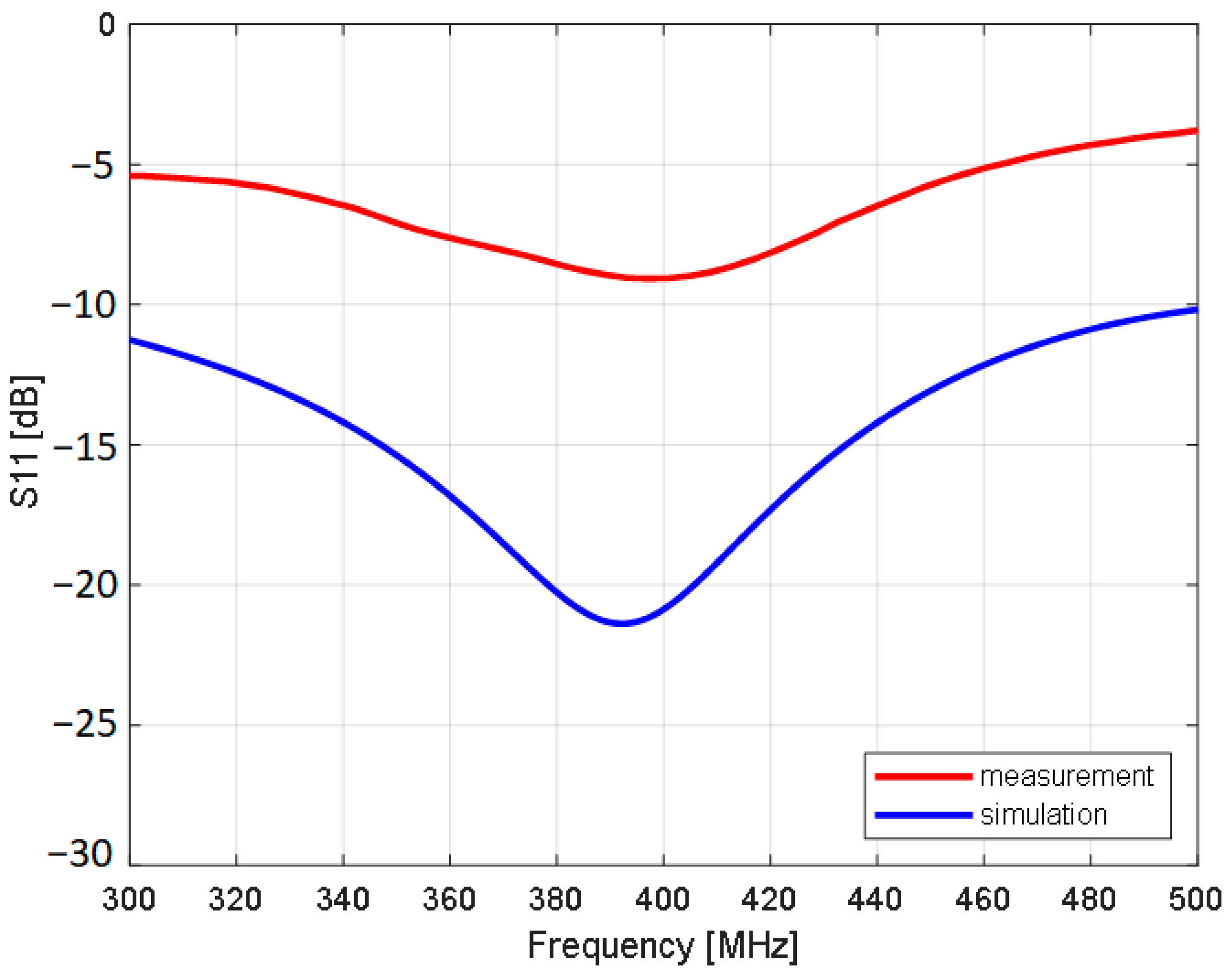
In Figure 14 the measurements results of antenna impedance matching to 50 Ω are presented. 
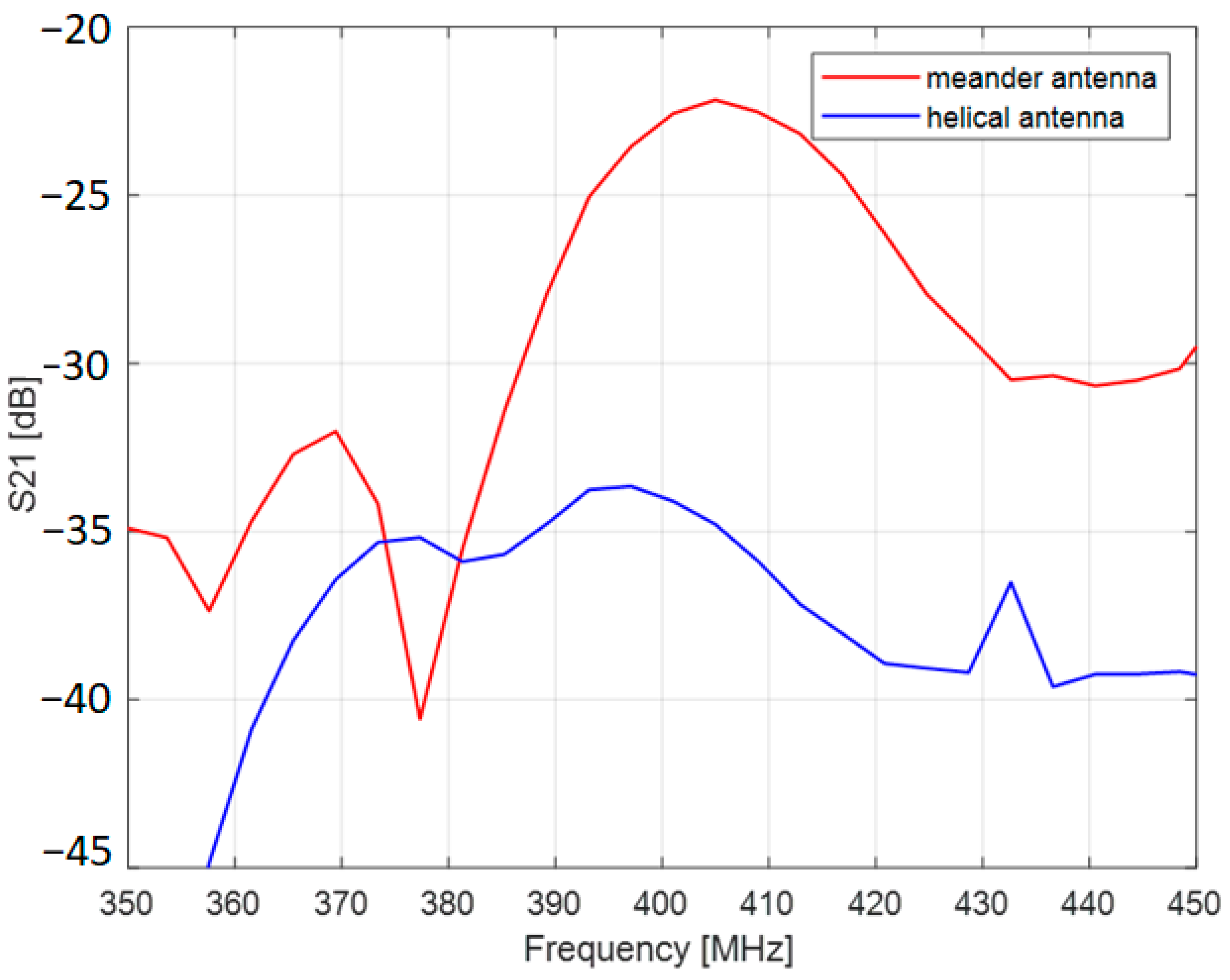
Figure 15 shows the result of S21 measurements between endoscopic antenna and external helical antenna. The endoscopic antenna was placed in the middle of the body phantom.
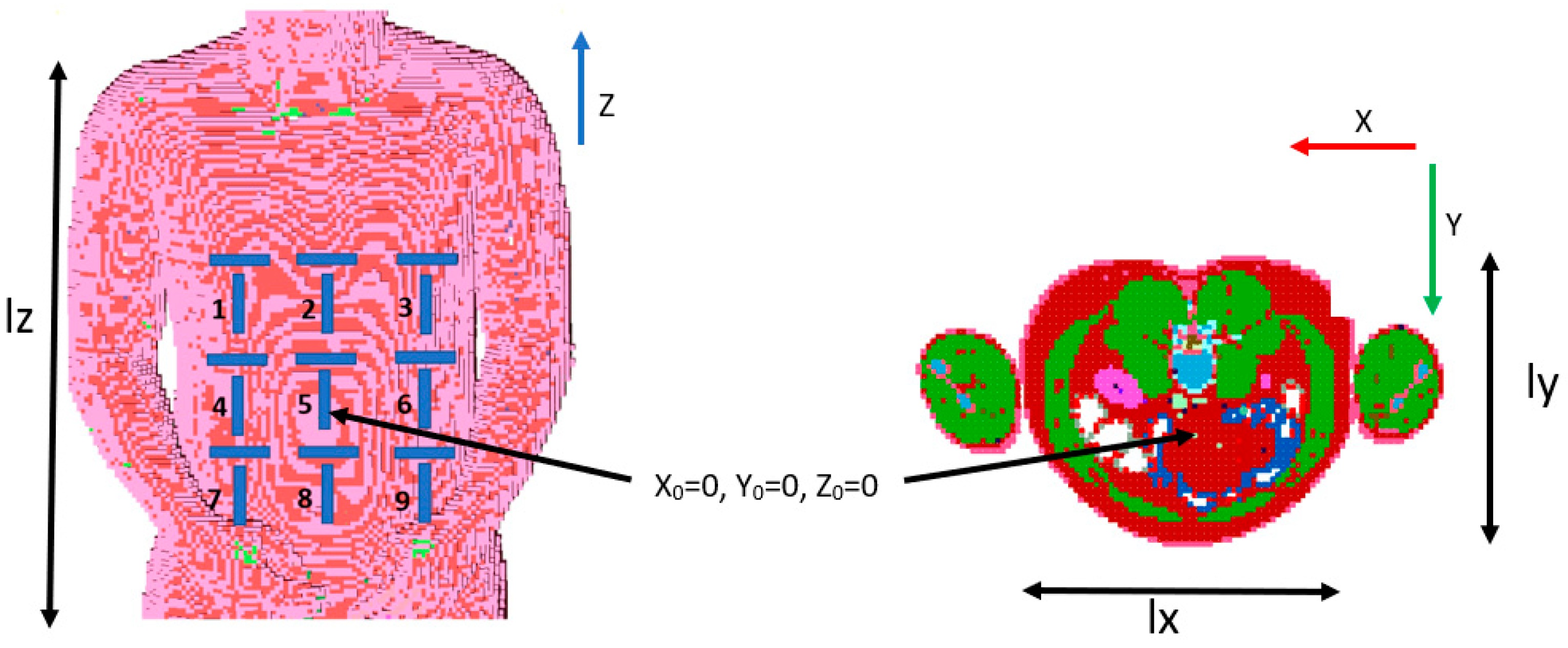
The antenna performance was then validated with the algorithm for capsule localization. Input data were obtained with computer simulations. Remcom XFdtd software version 7.8.1 and its NMR heterogenous human body model with a 5 mm voxel size were used for this purpose. The adopted heterogenous model represents the exact structure of the human body defined by 39 different materials [25]. Each organ consists of cuboids with which electrical parameters correspond to parameters of human tissues. The cross section of the adopted body model is presented in Figure 16, different tissues are represented with different materials colors. In the simulated scenario, a set of 160 predefined capsule positions in the area of the digestive system was examined. Taking into account dimensions of the model and coordinate system presented in Figure 16, capsule positions were changed in the following range: x = ±70 mm, y = ±30 mm, and z = ±150 mm. As the endoscope operates mainly in MICS band, simulations were carried out for frequencies 401 MHz and 406 MHz.
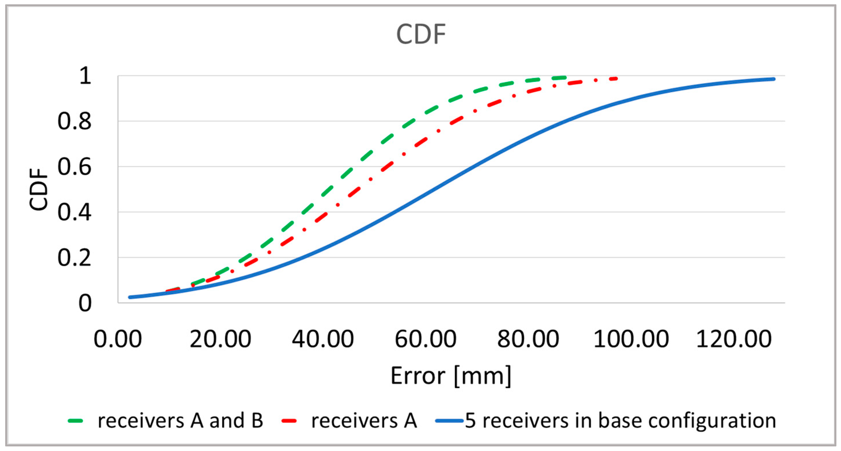
Figure 17 shows the results of the analysis of the localization error with the adaptive body model and the algorithm for the automatic external receivers selection. Taking into account the fact that the orientation of the endoscopic capsule affects the location error, two versions of the receiver arrangement were compared: receivers arranged vertically (Ak) and receivers arranged vertically and horizontally (Ak and Bk). The presented location error described by Formula (9) [8] was defined as the distance between the actual position of the capsule and the estimated position.
L e = x t x e s t 2 + y t y e s t 2 + z t z e s t 2
where xt, yt, zt is the actual position;
xest, yest, zest is the estimated position.
The dynamic recivers selection together with the proposed conformal zig-zag antenna improves localization accuracy by about 35%. 
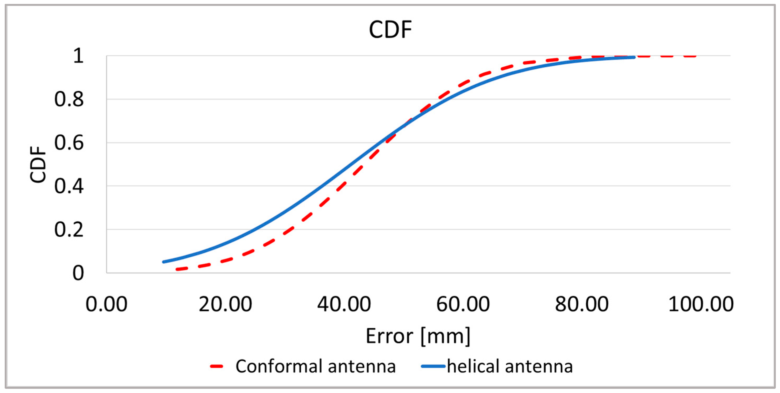
Figure 18 presents the localization error collectively for around 160 investigated capsule positions in different parts of the digestive tract. Results shows that the proposed antenna allows to reduce maximum localization error while the average error is similar to the helical antenna.
In the localization process capsule that travels along the digestive tract is surrounded by different tissues and the localization error may be dependent on attenuation introduced by different tissues. Figure 19 shows localization error for the capsule that was palced in different parts of digestive tract obtained with the heterogenus human body model. The worst localization accuray is observed in the large intestine despite the fact that according to Table 3 the attenuation here is the smallest. In the heterogenous model, different parts of digestive system (tissues in Figure 16) are loceted at different distances to the receiving antennas which also affect received signal strength, delay, and overall performance of the localization system.
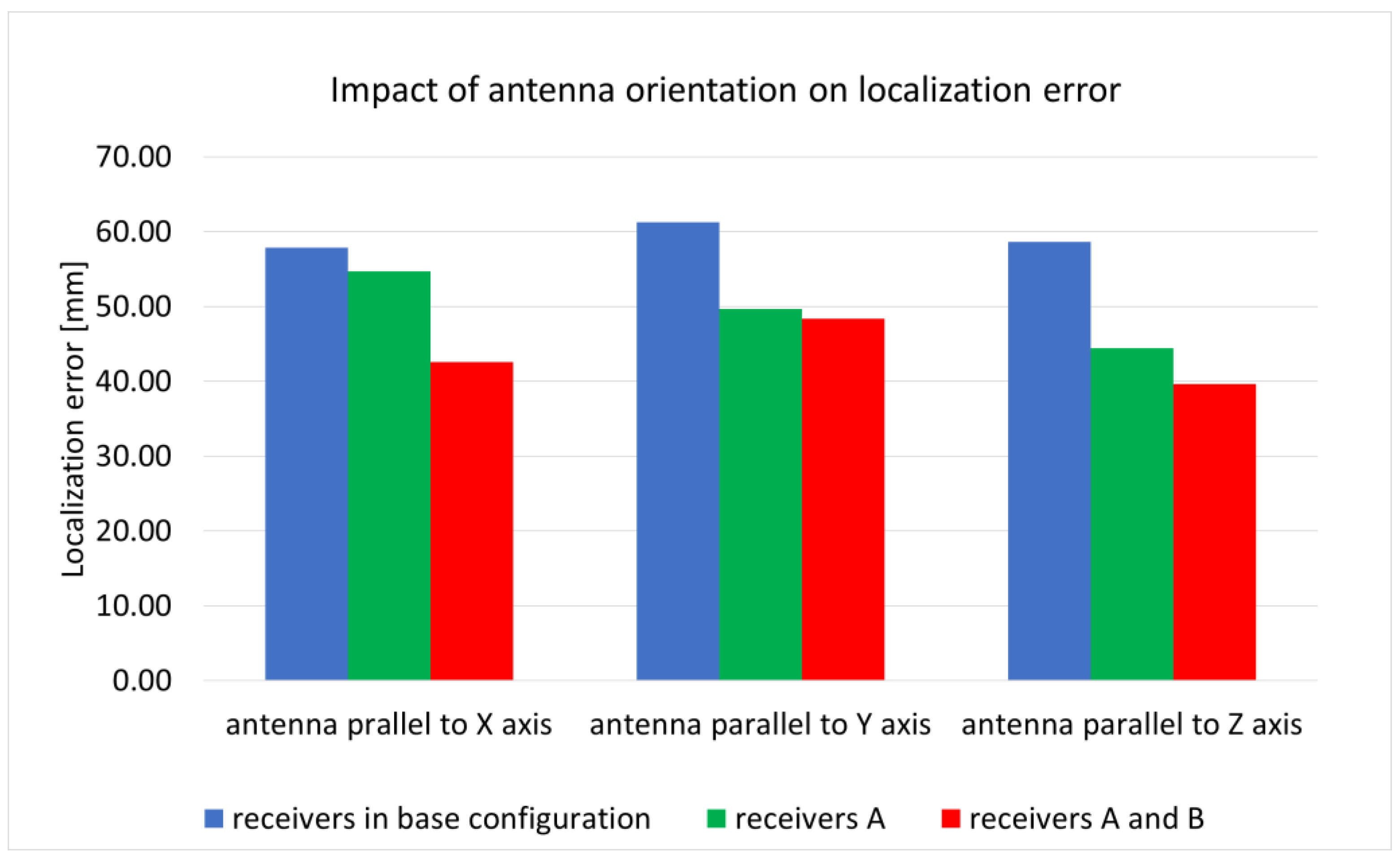
The endoscopic capsule, moving along the digestive tract, changes its orientation in relation to external receivers. The orientation of the capsule has an impact on the signal as well as the human body. The research carried out so far showed that in the case of a helical antenna, a change in orientation can increase the average location error by up to 10 mm. For this reason, additional B receivers arranged horizontally as presented on Figure 7b were introduced to minimize the influence of the capsule antenna orientation on the localization accuracy. To check antenna orientation, the impact of localization accuracy simulations were carried out in which the capsule antenna was rotated by 90° around the X and Y axis. Results presented in the 
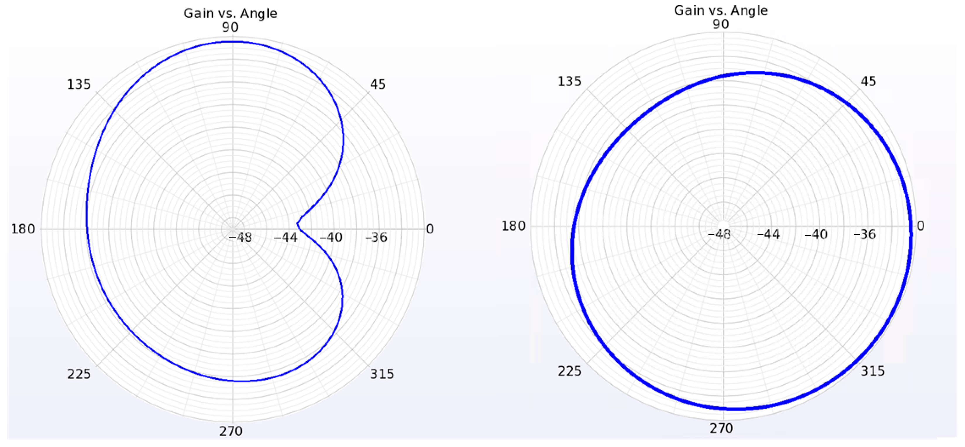
Figure 20 show that additional receivers improved localization accuracy. This is the most visible when the antenna is parallel to the X axis. The lowest improvement is visible when the antenna is parallel to the Y axis. This is because according to radiation pattern presented on Figure 6 the radiation efficiency for the proposed conformal antenna is the lowest in the direction of the Y axis.

4. Discussion

The results of antenna impedance matching simulations show that the conformal zig-zag antenna has a bandwidth within the 400 MHz band that is dedicated to endoscopic capsules. As it was presented in Figure 9 the antenna preserves good impedance matching being exposed to different tissue materials. As presented in Figure 14 the results of antenna impedance matching differ between measurement and simulation. Even if the frequency for which the minimum of S11 is the same (400 MHz), the value in the case of measurement is greater than 12 dB. This is the result of differences between the numerical model and fabricated prototype. As presented in Figure 12, the antenna radiator is fabricated on a thin film substrate. During prototype antenna assembly the air gap had to be applied to insert the radiator between the inner and outer piece of cover. This can result in radiator displacement towards the cover. Moreover, the soldering pads and coaxial connection was not included in the simulation. The antenna was etched in sodium persulfate. The etching process requires applying a mask to the flexible laminate. In our case, a laser printer was used, but due to the poor adhesion of the toner to the laminate, the mask had imperfections. For this reason, the shape of the antenna used in the simulation slightly differs from the prototype. This can also be the cause of discrepancies between the simulation and measurement results.
The results of antenna radiation pattern simulations (Figure 6) show that the maximum gain of the antenna that is surrounded by lossy tissues is low (−32.2 dBi). It has omnidirectional distribution of the power gain in the plane that is perpendicular to the antenna axis. This is a desirable feature for antennas intended for use in wireless location systems, since changing the orientation of the antenna has less impact on the level of received power. As a result, the phase shift estimation error is smaller.
The attenuation of the signal between the receiving antenna and capsule was simulated as the system loss, using scattering matrix parameters. It was used to compare the proposed antenna with the helical one used in a previous study. For assumed simulation environment, an improvement of up to 9 dB was obtained. Moreover, the proposed conformal antenna is suitable to be used in endoscope capsules because it can be fabricated in the side of the capsule, preserving the internal volume for other electronic components.
The algorithm with automatic selection of external receivers significantly improves location accuracy. Using only receivers placed vertically, the location error was reduced by about 20% compared with the original algorithm. Adding additional horizontal receivers, the error was lower by about 35%. The average location error was 42 mm. The improvement in localization accuracy was observed in about 85% of cases.
An advantage of the proposed method Is that it can be used for patients with different body proportions and may by implemented in wearable systems. This increases usability of the localization system.
Research on localization the algorithm presented in this paper is limited to computer simulations. This is because in the case of transmitters that are operating inside human body experimental verification with measurements is extremely difficult to be performed and requires the agreement of bio-ethical commission. Only measurements with physical simplified phantoms are possible at this stage of research. Therefore, we performed the antenna measurements in the body phantom. Moreover, the influence of body motion on the localization algorithm was not covered here since we had access to a numerical model of a human body in one pose (lying person). Even small movements of the chest and diaphragm caused by breathing can affect the accuracy of the location, especially from the external receivers placed on the front of the torso. The impact of anatomical differences among different human subjects was not investigated at this stage due to lack of other numerical body models available in our simulation setup.
The results of the simulation clearly show that both the position of external receivers and the transmitting antenna type has an effect on the algorithm’s accuracy. The localization error was reduced by about 20 mm for a zig-zag conformal antenna when the dynamic receiver selections were employed.

5. Conclusions

In this paper the meander zig-zag conformal antenna was presented. Its performance was examined based on computer simulations. The proposed antenna provides better transmitting power efficiency providing similar localization accuracy as previously used in the helical model.
The method of wireless endoscope capsules localization with the use of the phase detection algorithm and simplified human body model was improved by the dynamic receiver selection algorithm. The proposed method chooses receivers with the highest level of received signal. This allows to significantly improve localization accuracy. Simulations show that using an adaptive model permittivity and dynamic receiver selection in the localization algorithm not only increases localization accuracy but also enables algorithm convergence for a larger number of analyzed capsule positions.
The main advantage of the proposed method is that it can be adapted to patients of different body structure without information of internal structure and electrical parameters of individual tissues. Due to this, it is not necessary to prepare expensive and time-consuming body models for each patient. The lack of knowledge about the exact structure of a patient’s body makes the localization error higher than in the case of techniques that use information about the distribution of magnetic field strength or NMR scans made individually for each patient. The proposed approach allows to reduce the localization error that results from the lack of precise knowledge of the propagation environment.
The proposed conformal antenna verification with localization algorithm in physical phantoms of the human body will be the final assessment of this system in the study of the wireless endoscopes localization in digestive systems.

Author Contributions

Conceptualization, P.O. and Ł.J.; Formal analysis, Ł.J.; Investigation, P.O.; Methodology, P.O. and Ł.J.; Software, P.O.; Validation, P.O.; Visualization, P.O.; Writing—original draft, P.O. and Ł.J.; Writing—review and editing, Ł.J. All authors have read and agreed to the published version of the manuscript.

Funding

This research received no external funding.

Institutional Review Board Statement

Not applicable.

Informed Consent Statement

Not applicable.

Data Availability Statement

The simulation results are available upon email request.

Conflicts of Interest

The authors declare no conflict of interest.

References

  1. Wallace, M.B.; Fockens, P.; Sung, J.J. Gastroenterological Endoscopy; Thieme Medical Publishers, Incorporated: New York, NY, USA, 2018. [Google Scholar]
  2. Cavlu, V.; Brennan, P. Determining the Position and Orientation of In-Body Medical Instruments Using Near-Field Magnetic Field Mapping. IEEE J. Electromagn. RF Microw. Med. Biol. 2019, 4, 10–16. [Google Scholar] [CrossRef]
  3. Goh, S.T.; Zekavat, S.A.; Pahlavan, K. DOA-Based Endoscopy Capsule Localization and Orientation Estimation via Unscented Kalman Filter. IEEE Sens. J. 2014, 14, 3819–3829. [Google Scholar]
  4. Kim, M.-C.; Kim, E.-S.; Park, J.-O.; Choi, E.; Kim, C.-S. Robotic Localization Based on Planar Cable Robot and Hall Sensor Array Applied to Magnetic Capsule Endoscope. Sensors 2020, 20, 5728. [Google Scholar] [CrossRef] [PubMed]
  5. Dey, N.; Ashour, A.S.; Shi, F.; Sherratt, R.S. Wireless Capsule Gastrointestinal Endoscopy: Direction-of-Arrival Estimation Based Localization Survey. IEEE Rev. Biomed. Eng. 2017, 10, 2–11. [Google Scholar] [CrossRef] [PubMed]
  6. Khan, W.; Kabir, S.M.L.; Khan, H.A.; Al Helal, A.; Mukit, M.A.; Mostafa, R. A localization algorithm for capsule endoscopy based on feature point tracking. In Proceedings of the 2016 International Conference on Medical Engineering, Health Informatics and Technology (MediTec), Dhaka, Bangladesh, 17–18 December 2016; pp. 1–5. [Google Scholar]
  7. Vedaei, S.S.; Wahid, K.A. A localization method for wireless capsule endoscopy using side wall cameras and IMU sensor. Sci. Rep. 2021, 11, 11204. [Google Scholar] [CrossRef] [PubMed]
  8. Oleksy, P.; Januszkiewicz, L. Wireless Capsule Endoscope Localization with Phase Detection Algorithm and Adaptive Body Model Sensors. Int. J. Electron. Telecommun. 2022, 22, 2200. [Google Scholar]
  9. Mezher, M.A.; Din, S.; Ilyas, M.; Bayat, O.; Abbasi, Q.H.; Ashraf, I. Data Transmission Enhancement Using Optimal Coding Technique Over In Vivo Channel for Interbody Communication. Big Data 2022. [Google Scholar] [CrossRef] [PubMed]
  10. Ionescu, A.G.; Glodeanu, A.D.; Ionescu, M.; Zaharie, S.I.; Ciurea, A.M.; Golli, A.L.; Mavritsakis, N.; Popa, D.L.; Vere, C.C. Clinical impact of wireless capsule endoscopy for small bowel investigation (Review). Exp. Ther. Med. 2022, 23, 262. [Google Scholar] [CrossRef] [PubMed]
  11. Savci, H.S.; Sula, A.; Wang, Z.; Dogan, N.S.; Arvas, E. MICS transceivers: Regulatory standards and applications (medical implant communications service). In Proceedings of the IEEE SoutheastCon, Ft. Lauderdale, FL, USA, 8–10 April 2005; pp. 179–182. [Google Scholar]
  12. Wotherspoon, T.K.; Higgins, M. Implantable wireless body area networks. In Implantable Sensor Systems for Medical Applications; Woodhead Publishing Series in Biomaterials; Woodhead Publishing: Soston, UK, 2013; pp. 437–468. [Google Scholar]
  13. Kwak, S.I.; Chang, K.; Yoon, Y.J. The helical antenna for the capsule endoscope. In Proceedings of the 2005 IEEE Antennas and Propagation Society International Symposium, Washington, DC, USA, 3–8 July 2005; Volume 2B, pp. 804–807. [Google Scholar]
  14. Feng, Y.; Li, Z.; Qi, L. A compact and miniaturized implantable antenna for ISM band in wireless cardiac pacemaker system. Sci. Rep. 2022, 12, 238. [Google Scholar] [CrossRef] [PubMed]
  15. Shah, I.A.; Zada, M.; Yoo, H. Design and analysis of a compact-sized multiband spiral-shaped implantable antenna for scalp implantable and leadless pacemaker systems. IEEE Trans. Antennas Propag. 2019, 67, 4230–4234. [Google Scholar] [CrossRef]
  16. Faisal, F.; Yoo, H. A miniaturized novel-shape dual-band antenna for implantable applications. IEEE Trans. Antennas Propag. 2019, 67, 774–783. [Google Scholar] [CrossRef]
  17. Wang, J.; Leach, M.; Lim, E.G.; Wang, Z.; Pei, R.; Huang, Y. An Implantable and Conformal Antenna for Wireless Capsule Endoscopy. IEEE Antennas Wirel. Propag. Lett. 2018, 17, 1153–1157. [Google Scholar] [CrossRef]
  18. Basir, A.; Zada, M.; Cho, Y.; Yoo, H. A Dual-Circular-Polarized Endoscopic Antenna With Wideband Characteristics and Wireless Biotelemetric Link Characterization. IEEE Trans. Antennas Propag. 2020, 68, 6953–6963. [Google Scholar] [CrossRef]
  19. Shang, J.; Yu, Y. An ultrawideband and conformal antenna for wireless capsule endoscop. Microw. Opt. Technol. Lett. 2020, 62, 860–865. [Google Scholar] [CrossRef]
  20. Suzan Miah, M.; Khan, A.N.; Icheln, C.; Haneda, K.; Takizawa, K.-I. Antenna system design for improved wireless capsule endoscope links at 433 MHz. IEEE Trans. Antennas Propag. 2019, 67, 2687–2699. [Google Scholar] [CrossRef]
  21. Alemaryeen, A. Compact wideband antenna for wireless capsule endoscopy system. Appl. Phys. A 2021, 127, 271. [Google Scholar] [CrossRef]
  22. Luo, Y. A Wide-band Inner-wall Conformal Antenna for Wireless Capsule Endoscopy. In Proceedings of the IEEE International Symposium on Antennas and Propagation and USNC-URSI Radio Science Meeting (APS/URSI), Singapore, 4–10 December 2021; pp. 537–538. [Google Scholar]
  23. Zhang, G.; Song, X.; Yu, Z.; An, X. A Symmetrical Closed-Loop Conformal Antenna With Wideband for Capsule Endoscope. IEEE Antennas Wirel. Propag. Lett. 2021, 20, 1918–1922. [Google Scholar] [CrossRef]
  24. Januszkiewicz, L. Simplified human body models for interference analysis in the cognitive radio for medical body area networks. In Proceedings of the 2014 8th International Symposium on Medical Information and Communication Technology (ISMICT), Firenze, Italy, 2–4 April 2014; pp. 1–5. [Google Scholar]
  25. Remcom Inc. XFdtd 7.5.0.3 Reference Manual; Remcom Inc.: State College, PA, USA, 2012. [Google Scholar]
  26. Oleksy, P.; Januszkiewicz, Ł. Wireless Capsule Endoscope Localization with Phase Detection Algorithm and Simplified Human Body Model. Int. J. Electron. Telecommun. 2020, 66, 45–51. [Google Scholar]
  27. Toropainen, A.; Vainikainen, P.; Drossos, A. Method for accurate measurement of complex permittivity of tissue equivalent liquids. Electron. Lett. 2000, 36, 32–34. [Google Scholar] [CrossRef]
Figure 1. Radiators of antennas that operate inside human body that use meander-shaped radiator (signal source marked with red circle): (a) antenna presented in [14], (b) [19], (c) [21], (d) antenna proposed by the authors in this paper.
Electronics 12 00784 g001
Figure 2. Antenna model in tissue simulant material.
Electronics 12 00784 g002
Figure 3. Proposed conformal zig-zag antenna layout and final shape, H = 20 mm, L = 33 mm, h = 9 mm, and d = 10 mm.
Electronics 12 00784 g003
Figure 4. Capsule model used in simulations.
Electronics 12 00784 g004
Figure 5. Impedance matching of the proposed conformal antenna presented on Figure 3.
Electronics 12 00784 g005
Figure 6. Antenna gain: left for YZ plane and right for X–Y plane (according to Figure 3).
Electronics 12 00784 g006
Figure 7. Arrangement of the external receivers on the human body, (a) base configuration presented in [9], (b) configuration used for adaptive receiver selection (Ak: vertical receivers; Bk: horizontal receivers), (c) receiving dipole Hd = 22 mm.
Electronics 12 00784 g007
Figure 8. Improved localization algorithm with automatic selection of external receivers.
Electronics 12 00784 g008
Figure 9. Impedance matching of the capsule antenna.
Electronics 12 00784 g009
Figure 10. Antenna verification setup (a) simulation setup with S parameters definition, (b) measurement setup.
Electronics 12 00784 g010
Figure 11. Impedance matching of the antenna placed in capsule model fabricated of PLA.
Electronics 12 00784 g011
Figure 12. Prototype of proposed meander antenna: (a) antenna with coaxial cable, (b) antenna radiator fabricated on Pyralux substrate, (c) antenna radiator being inserted into 3D-printed cover.
Electronics 12 00784 g012
Figure 13. DiLine measurement setup used for liquid verification (a) vector network analyzer connected to TEM line, (b) TEM line.
Electronics 12 00784 g013
Figure 14. S11 measured and simulated for meander antenna prototype.
Electronics 12 00784 g014
Figure 15. S21 measured for meander antenna prototype and helical antenna prototype.
Electronics 12 00784 g015
Figure 16. Dimensions of used human body model: lx = 330 mm, ly = 290 mm, lz = 650 mm, and adopted coordination system.
Electronics 12 00784 g016
Figure 17. Cumulative distribution function (CDF) of localization error for algorithm with adaptive receivers selection. Results for 160 capsule positions in the digestive tract.
Electronics 12 00784 g017
Figure 18. Cumulative distribution function (CDF): error comparison for helical and proposed conformal antenna with adaptive A and B receivers selection. Results for 160 capsule positions in the digestive tract.
Electronics 12 00784 g018
Figure 19. Cumulative distribution function (CDF), error comparison for different part of the digestive tract.
Electronics 12 00784 g019
Figure 20. Impact of antenna orientation on localization error.
Electronics 12 00784 g020
Table 1. Electrical properties capsule model materials.
Tissue Permittivity   ε r   Conductivity S [S/m]
Alumina9.80.0001
Glass4.90.002
FR4 laminate4.10.02
Silicon9.60.003
Table 2. Electrical properties of used tissues in antenna design and performance evaluation.
Tissue Permittivity   ε r   Conductivity S [S/m]
Average model570.76
Fat5.970.09
Large intestine53.92.04
Small intestine54.43.17
Stomach622.2
Table 3. The attenuation of signal between antennas (S parameters) for different tissues.
TissueHelical Antenna, |S| [dB]Conformal Antenna, |S| [dB]
Receiver A: S21Receiver B: S31Receiver A: S21Receiver B: S31
Average model−80.8−86.3−72.9−76.7
Fat−82−89.3−83.1−75.8
Large intestine−89−95.6−83.5−86.5
Small intestine−111.8−122.5−110.5−107.5
Stomach−89.4−96.2−83.7−86.4
Disclaimer/Publisher’s Note: The statements, opinions and data contained in all publications are solely those of the individual author(s) and contributor(s) and not of MDPI and/or the editor(s). MDPI and/or the editor(s) disclaim responsibility for any injury to people or property resulting from any ideas, methods, instructions or products referred to in the content.

