Article

Stability Control Strategies for Bidirectional Energy Storage Converters Considering AC Constant Power Loads

School of Electrical and Control Engineering, North China University of Technology, Beijing 100144, China
*
Author to whom correspondence should be addressed.
Electronics 2023, 12(4), 1067; https://doi.org/10.3390/electronics12041067
Submission received: 15 January 2023 / Revised: 16 February 2023 / Accepted: 18 February 2023 / Published: 20 February 2023

Abstract

:
In islanded AC microgrids, negative impedance characteristics of AC constant power loads (AC CPLs) easily introduce large signal instability to the system, while energy storage systems sometimes compensate for the dynamic characteristics of AC CPLs, and increase the system stability. Although energy storage control techniques and characteristics have gained a lot of attention, few studies have derived quantitative design guidelines for energy storage systems from the aspect of stability improvement. In order to fill this gap, this paper proposes stability control strategies for bidirectional energy storage converters considering the characteristics of AC CPLs to guarantee large signal stability of islanded AC microgrids. The presented control techniques create quantitative limits for the DC bus voltage loop control parameters of the energy storage DC/DC converter and the integral control loop control parameter of the energy storage DC/AC converter, and also interpret the positive stability influence of energy storage systems and the negative stability influence of AC CPLs. The structure of the paper is as follows. Firstly, DQ coordinate transformation is adopted, and AC microgrid nonlinear models with the energy storage system in charging and discharging states are constructed. Then, large signal models are constructed depending on mixed potential theory. Stability control strategies for bidirectional energy storage converters are obtained, and AC CPLs power, storage system equivalent resistor, and micro power source power are all taken into account. Finally, based on simulation and experimental results, it is obvious that regulating the control parameters of the energy storage converter significantly increases the large signal stability of islanded AC microgrids without extra equipment. The method is very simple and easy to implement.

1. Introduction

AC microgrids connect micro power sources, variable loads, and energy storage devices to the AC bus and integrate them effectively into the distribution network [1,2,3,4]. A majority of the load is connected to the bus via a converter with a closed-loop control system. These loads are typically categorized as AC constant power loads (AC CPLs) due to their constant active power [5,6,7]. As the bus voltage increases, the current of the AC CPLs will decrease. On the contrary, when the voltage decreases, the current simultaneously increases [8,9]. The changes in RMS voltages and currents are different; in other words, ΔVRMSIRMS < 0. That is, negative impedance characteristics are introduced by AC CPLs [10,11]. The negative impedance characteristic of AC CPLs is equivalent to positive feedback during the interference period and may amplify variations such as load steps, power source switching, etc. [12,13]. It is obvious that AC CPLs could easily cause instability problems. Unfortunately, when AC microgrids operate in islanded mode, the generated power is restricted to the rated value; because of AC CPLs, islanded AC microgrids are more susceptible to disturbances and may even fail to work normally [14,15,16,17].
A lot of research focuses on suppressing the characteristics of CPLs and increasing the stability of microgrids. Reference [18] proposes a new loop cancellation technology for microgrids. Typically, the average system model is employed to compute the adaptive gain of the system, and the unstable impact of DC CPLs is reduced. Reference [19] combines state space implementation and a nonlinear dynamic model of DC CPLs into a dynamic model of AC microgrids. Based on the stability theorem of Lyapunov and Popov, the stability conditions of the system are obtained, but the stability conditions may no longer apply when the system experiences large disturbances. Reference [20] derives a control method based on state feedback linearization to deal with the unstable effect of DC CPLs and ensure the stability of DC bus voltage. In reference [21], a novel closed-loop converter controller is constructed, and a sufficient condition for the large signal stability of the DC microgrid is established. Reference [22] proposes a composite stabilizer composed of a nonlinear disturbance observer and recursive inversion controller in order to stabilize all states of the converter in the sense of a large signal. Reference [23] utilizes Floquet theory to analyze the bifurcation of the system and clearly illustrates the stability influences of system parameters. Unfortunately, the majority of the literature performs stability analysis on DC microgrids, and the characteristics of DC CPLs are typically not taken into account [24]. At present, there are relatively few large signal stability analyses in AC microgrids, and AC CPLs are seldom taken into account.
In order to increase power supply reliability and quality, an energy storage system is extremely necessary for AC microgrids [25,26]. Furthermore, appropriate controls for energy storage systems could compensate dynamic characteristics of AC CPLs and enhance system stability [27,28]. References [29,30] predict power system transient stability by incorporating power system dynamics into the data collection process through machine learning models. Although energy storage control techniques and characteristics have gained a lot of attention, few studies have derived quantitative design guidelines for energy storage systems from the aspect of stability improvement. Consequently, investigating stability control analysis of energy storage converters to suppress influences of AC CPLs becomes very attractive.
In order to fill this gap, this paper proposes stability control strategies for bidirectional energy storage converters considering the characteristics of AC CPLs to guarantee large signal stability of islanded AC microgrids based on mixed potential theory. Firstly, DQ coordinate transformation is used to develop simplified nonlinear models of AC microgrids separately for the charging and discharging states of the energy storage system, as shown in Section 2. Then, based on the mixed potential function, large signal models are established and analyzed in Section 3. In Section 4, stability control strategies for bidirectional energy storage converters are obtained depending on AC CPLs, energy storage systems, and micro power sources. Finally, Section 5 shows simulations and experimental findings to validate the suggested control techniques for the DCDC converter and DC-AC converter used for energy storage. The contribution of this work is summarized as follows.
(1)
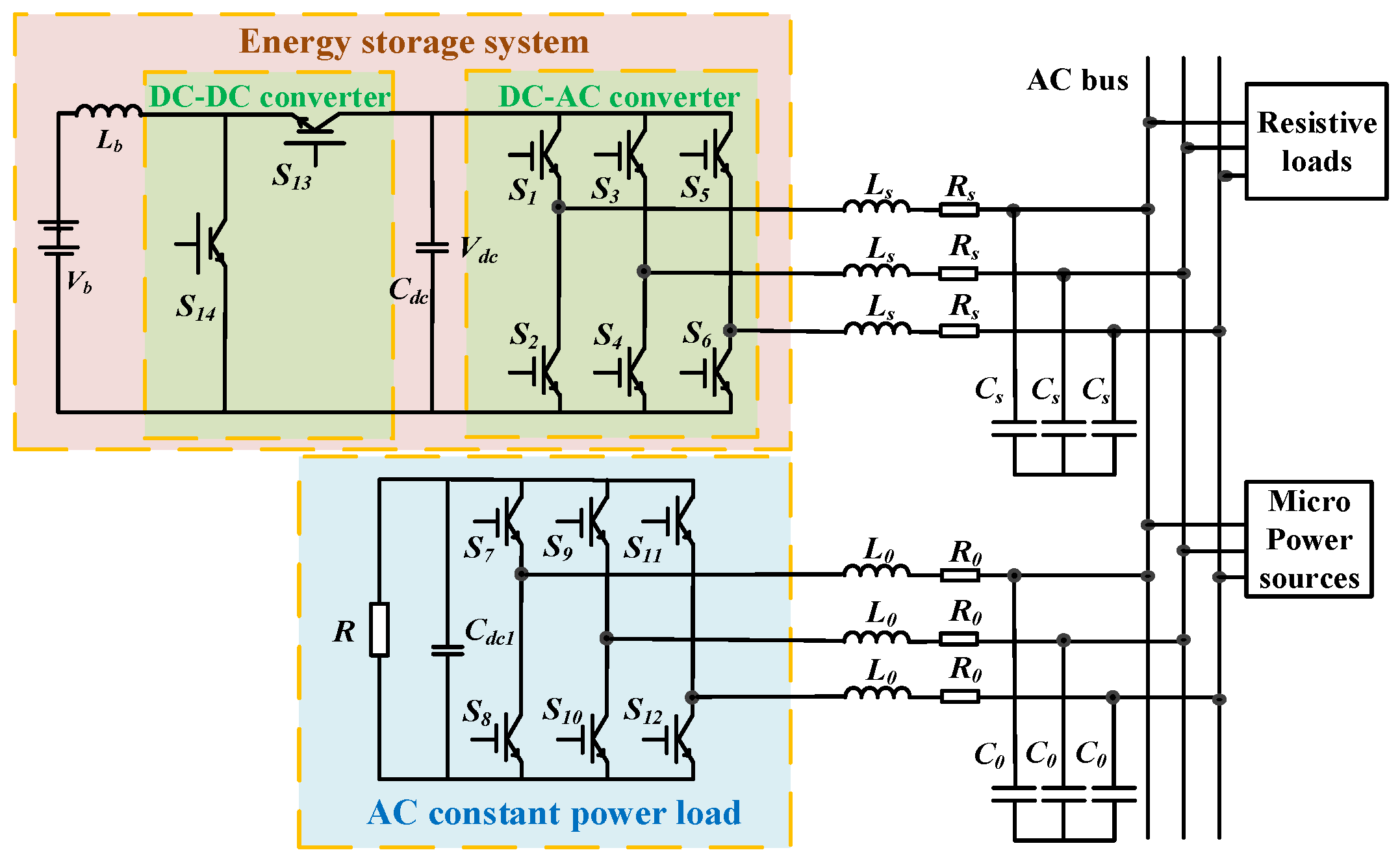
When the energy storage system is in charging and discharging states, nonlinear models of AC microgrids consisting of micro power sources, variable loads, and energy storage devices are constructed in a rotating coordinate frame.
(2)
The presented control techniques provide quantitative limits for the DC bus voltage loop control parameters of the energy storage DC/DC converter and the integral control loop control parameter of the energy storage DC/AC converter, and also interpret the positive stability influence of energy storage systems and micro power source, and the negative stability influence of AC CPLs.
(3)
The stability control strategies offer an important design basis for storage system converter control parameters and are very simple and easily implemented. Regulating outer voltage loop control parameters kp of energy storage DC/DC converter and inner current loop control parameters kip of DC/AC converter significantly increases large signal stability of islanded AC microgrids without extra equipment.

2. Simplified Nonlinear Models of AC Microgrids

2.1. AC Microgrids Characteristics

AC microgrids include AC CPLs, energy storage systems, resistive loads, and distributed micro power sources, as shown in Figure 1. Through a bidirectional DC/AC converter and a DC/DC converter, the AC bus is linked to the energy storage system. The AC CPL is denoted by a rectifier with constant power control and a resistor R.
The rectifier of AC CPL uses a PI control strategy to ensure that the voltage value on both sides of the resistance is constant. Consequently, the active power utilized by AC CPL can be assumed to remain constant. As the bus RMS voltage increases, the current of the AC CPL will decrease. On the contrary, when the voltage decreases, the current simultaneously increases. As can be seen in Figure 2, a negative value is obtained when the RMS voltage changes are divided by the RMS current changes, satisfying ΔVRMSIRMS < 0. The AC CPL exhibits negative impedance characteristics. The negative impedance characteristics of AC CPLs, which are equal to positive feedback when the bus voltage swings, make the system more unstable.
The energy storage system is connected to the AC bus through a bidirectional DC-DC converter and a DC-AC converter. Figure 3 depicts the process that is used to regulate the DC-DC converter. To keep the DC voltage constant, the DC-DC converter has two PI control loops. It consists of voltage outer-loop control and current inner-loop control, respectively. Both the charging and discharging states are selected arbitrarily by the system. If vdc < vdcref, the energy storage system will discharge. On the other hand, if vdc > vdcref, the energy storage system will charge. The values of the (vdcrefvdc) are used as inputs for the PI charging voltage controller and the PI discharging voltage controller. The reference currents ib1ref and ib2ref are the outputs of the controllers, respectively. Then, ib1ref and ib2ref become inputs of the inner PI charging and discharging current controllers. Then, reference currents are compared with actual currents, and finally, PWM signals for charging and discharging are obtained from the current controllers separately.
Figure 3 shows charging current ib1ref and reference discharge current ib2ref.
i b 1 r e f = k p c v d c r e f v d c + k i c 0 t v d c r e f v d c d t
i b 2 e f = k p d v d c r e f v d c + k i d 0 t v d c r e f v d c d t
In (1), kp(c) and ki(c) are proportional and integral parameters of the outer charging voltage controller, respectively. Alternatively, kp(d) and ki(d) represent the proportional and integral parameters of the outer discharging voltage controller, respectively.
The bidirectional DC-AC converter of the energy storage system is shown in Figure 4. According to ABC-DQ coordinate transformation, the DC-AC converter utilizes a droop controller to achieve reference voltages vdcref and vqcref. After that, double PI closed-loop control techniques are implemented. The difference values of reference voltage vdcref and actual voltage vdc are taken as inputs of the outer PI voltage controller and reference active current idref is obtained. Due to the fact that the system operates at unity power factor, the reference reactive current iqref = 0. Practical active current id and reactive current iq are both obtained from practical currents Iabc through ABC/DQ coordinate transformation. The difference values of iqref and id are inputs of the inner PI current controller, and inductively coupled component ωLid is also taken into account. Finally, vd is achieved. Similarly, vq is also obtained. Through DQ/ABC coordinate transformation, PWM signals for the bidirectional DC-AC converter are gained.
The DC-AC converter’s output internal current and DC voltage control loops are depicted as follows:
v d = k i p i d r e f i d + k i i i d r e f i d d t + ω L i q
v q = k i p i q r e f i q + k i i i q r e f i q d t ω L i d
The proportional parameter of the inner loop current controller in (3) and (4) is kip, whereas the integral value is kii.

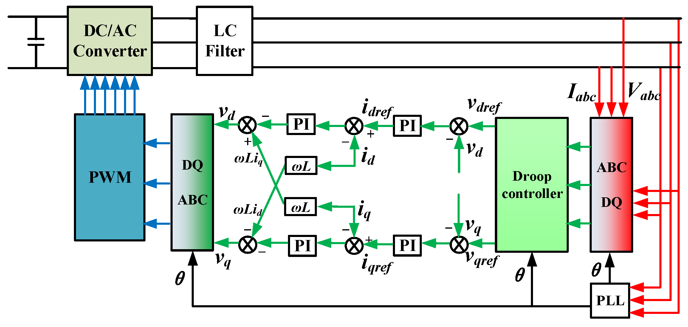
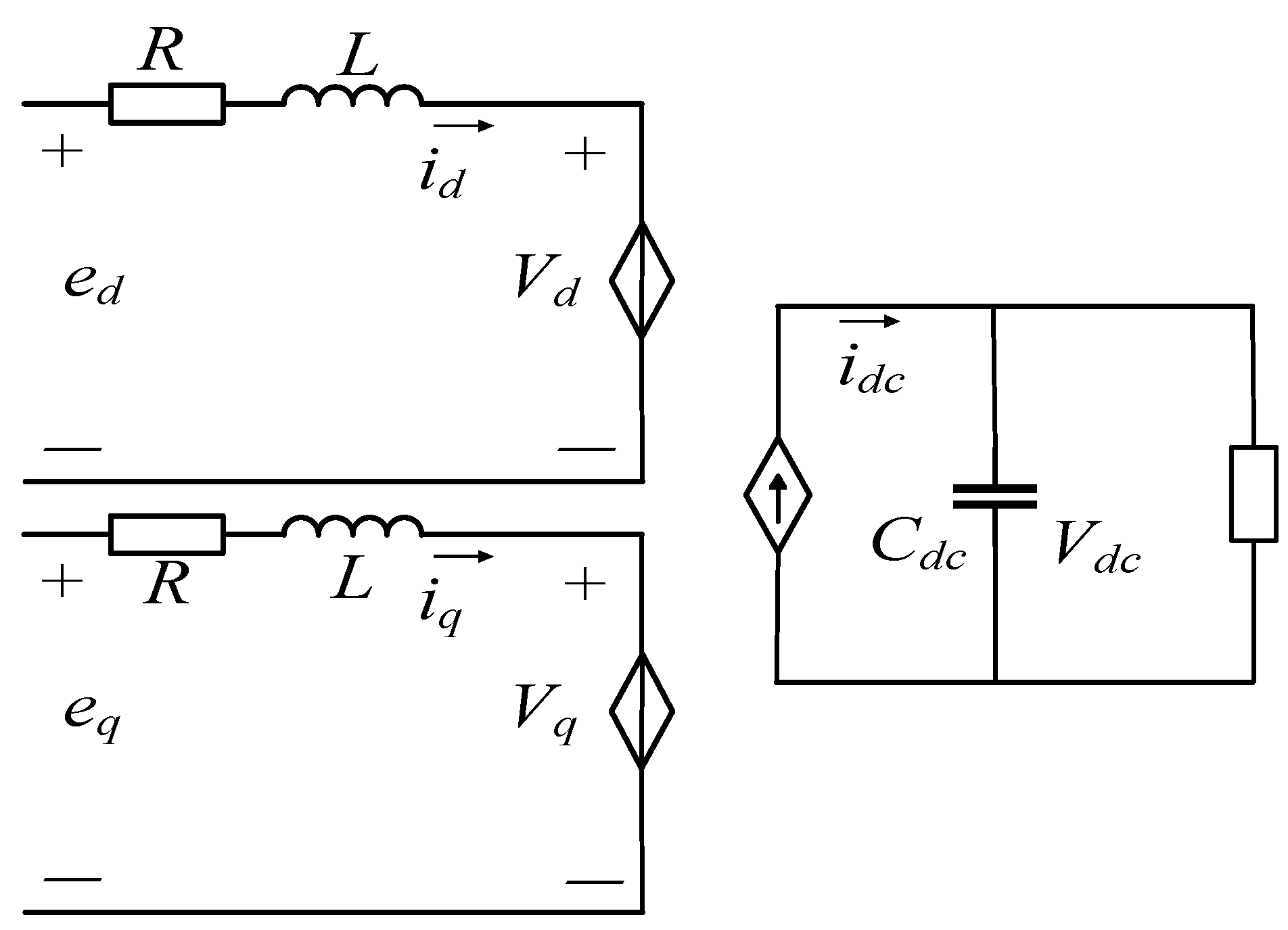
2.2. The Model of a Rotating Coordinate System DC-AC Converter

In order to obtain models of bidirectional DC-AC converters in AC microgrids, DQ coordinate transformation is utilized.
Figure 5 depicts the simplified construction of a DC-AC converter. ed and eq represent the instantaneous value of the electromotive force in the dq axis coordinate after coordinate transformation, and L denotes the inductance of the filter on the AC bus side. RL is the equivalent resistance based on energy loss and switching state, L is the inductance of the AC measurement filter, and C is the DC side filter capacitor. eL is the electromotive force on the DC side, Pb is the constant power load on the DC side, and vdc is the DC voltage.
L d i d d t ω L i d + R L i d = e d v d L d i q d t + ω L i d + R L i q = e q v q d v d c d t = i d c i L C
In (5), iL represents the current through resistor RL, ed is the vector of the grid electromotive force E projected on the d-axis, and idc is DC side current.
References [29,30] predict power system transient stability by incorporating power system dynamics into the data collection process through machine learning models. Active power may be transported between the rectifier station and the inverter station; however, reactive power does not go through the converter [31,32]. Consequently, only the d-axis component is typically taken into account when examining the DC side’s stability. According to (5), the DC-AC converter can be viewed as a two-port network circuit. As depicted in Figure 5, the D-axis voltage of the converter output is Vd, whereas the Q-axis voltage is Vq.

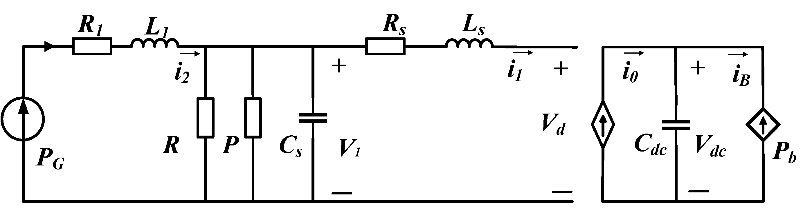
2.3. Nonlinear Models of AC Microgrids

Micro power sources in islanded AC microgrids are modeled as a current source PG, and AC constant power load is represented by P = VRMSIRMS = constant. The battery and DC-DC converter are treated as the Pb-regulated power source as a whole, which is equivalent to the energy storage system during discharge. When the energy storage system is being charged, the entire DC-DC converter is active, and batteries are modeled as a controllable resistor Rb. However, these electronics are more likely to cause destabilizing behaviors at their source interfaces due to the potential for negative impedance instability [33,34].
Based on the discharge state of the energy storage system, the nonlinear construction model of an AC microgrid in a rotating dq coordinate system is created in Figure 6. L1 and R1 are equivalent line inductance and resistance. LS and RS are analogous resistance and filter inductance. P represents the power of AC constant load. R is the resistance of AC resistive load. PG is the power of the micro power source. Pb is the discharging power of the energy storage system. Cdc is the DC side voltage stabilization capacitance. Vdc is the voltage of capacitance Cdc. The controlled current source’s current is denoted by i0. iB represents the DC-DC converter’s high voltage side current. Vd is the vector of the d-axis AC voltage.
Similarly, the nonlinear construction model of the AC microgrid in a dq rotating coordinate system is constructed when the energy storage system is charging, as shown in Figure 7.

3. AC Microgrid Stability Analysis Method for Large Signals

3.1. Large Signal Model When the Energy Storage System Is in a Discharging Condition

In 1964, J.K. Moser and R.K. Brayton proposed the mixed potential theory, which has been widely used in the modeling and analysis of nonlinear systems [35]. As a special form of mixed potential function, the Lyapunov function can obtain quantitative stability criteria and asymptotic stability region [36,37]. For nonlinear circuits of different structures, a unified form is shown as:
L d i ρ d t = P i , v i ρ C d v σ d t = P i , v v σ
In (6), P is called the mixed potential function, and L is the inductance element in the circuit. C is the capacitive element in the circuit, and vσ is the capacitor voltage.
The mixed potential function consists of the voltage potential function and the current potential function. The usual form of the mixed potential function is:
P * i , v = μ 1 μ 2 2 P i , v + 1 2 P i , L 1 P i + 1 2 P v , C 1 P v
Based on the nonlinear model of AC microgrids shown in Figure 6, when the energy storage device is in the discharge state, the mixed potential function model of the AC microgrid is:
P i , v = 0 i 2 P G i 2 d i 1 2 i 2 2 R 1 1 2 i 1 2 R s + 1 2 V 1 2 R + 0 V 1 P V 1 d v V d i 1 0 V d c i 0 d v 0 V d c P b V d c d v i 2 V 1 + i 1 V 1
According to (8), current potential function is:
A i = 1 2 i 1 2 R s + V d i 1 0 0 0 i 2 P G i 2 d i + 1 2 i 2 2 R 1
Voltage potential function is:
B v = 0 V 1 P V 1 d v + 1 2 V 1 2 R 0 0 0 v d c i 0 d v 0 V d c P b v d c d v
The validity of the developed mixed potential function is confirmed by (7). The system structure in Figure 6 and the model in (8) are both considered, and it is obtained:
P i , v i 1 = i 1 R s V d + v 1 = L s d i 1 d t P i , v i 2 = i 2 R 1 v 1 + P G i 2 = L 1 d i 2 d t P i , v v 1 = i 2 + i 1 + v 1 R + P v 1 = C d v 1 d t P i , v v d c = i 0 P b v d c = C d c d v d c d t

3.2. Large Signal Model When the Energy Storage System Is in a Charging Condition

Similarly, based on the nonlinear model of AC microgrids in Figure 7, the hybrid potential function model of an AC microgrid is as follows:
P i , v = 0 i 2 P G i 2 d i 1 2 i 2 2 R 1 1 2 i 1 2 R s + 1 2 V 1 2 R + 0 V 1 P V 1 d v v d i 1 0 V d c i 0 d v + 0 V d c V d c R b d v i 2 V 1 + i 1 V 1
The current potential function is:
A i = 1 2 i 1 2 R s + V d i 1 0 0 0 i 2 P G i 2 d i + 1 2 i 2 2 R 1
Voltage potential function is:
B v = 0 V 1 P V 1 d v + 1 2 V 1 2 R 0 0 0 v d c i 0 d v + 0 V d c V d c R b d v
Formula (6) is also used here to prove the validity of the model in (12). In accordance with the system architecture depicted in Figure 7 and the model in (12), it is obtained:
P i , v i 1 = i 1 R s V d + v 1 = L s d i 1 d t P i , v i 2 = i 2 R 1 v 1 + P G i 2 = L 1 d i 2 d t P i , v v 1 = i 2 + i 1 + v 1 R + P v 1 = C d v 1 d t P i , v v d c = i 0 + V d c R b = C d c d v d c d t
Formula (15) is also coincident with (6), and consequently, the mixed potential function model in (12) is valid.

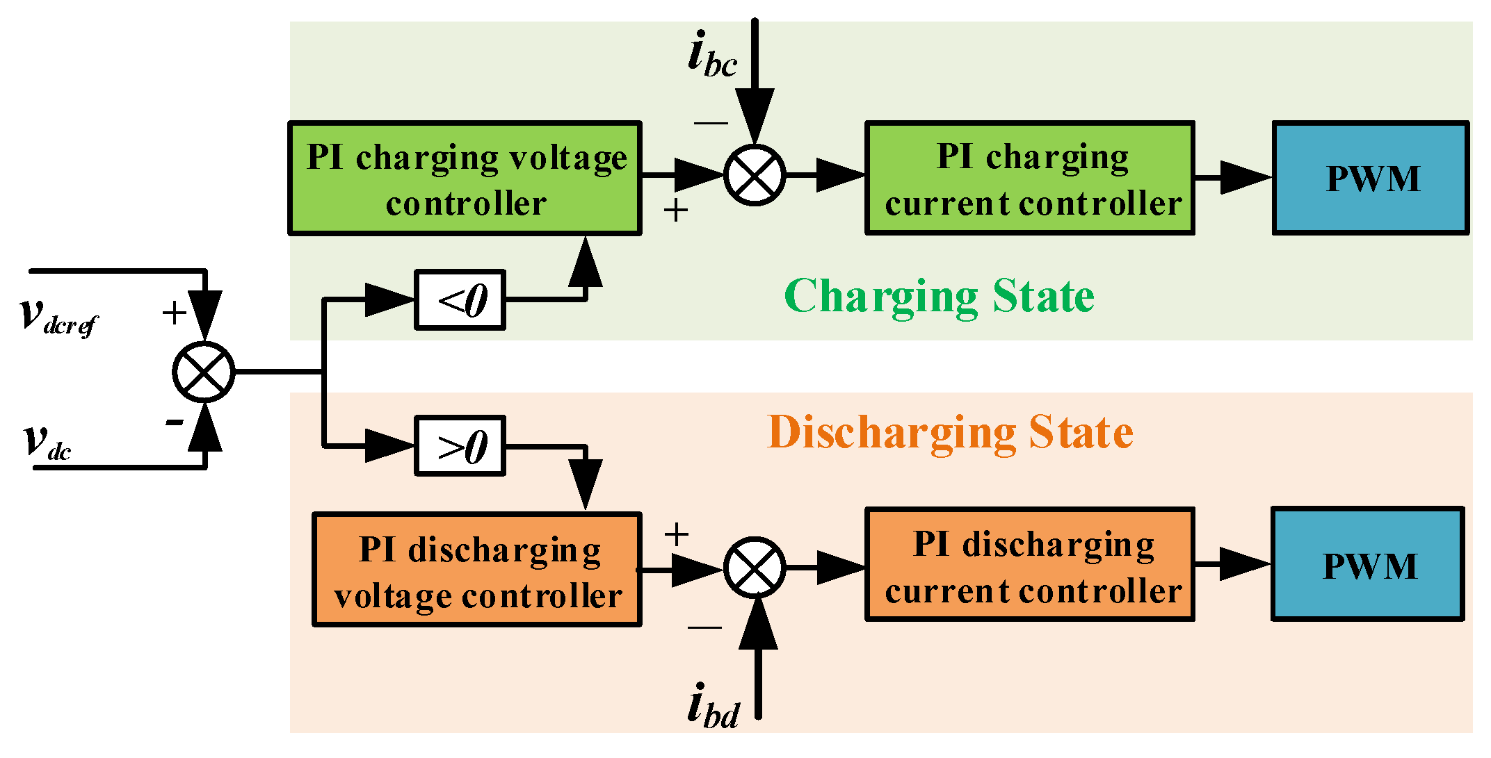
4. Stability Control Strategies for Energy Storage Converters

The large signal model of AC microgrids when the energy storage system is in the discharging state is depicted in Equation (8), and the big signal model of AC microgrids when the energy storage system is in the charging state is depicted in Equation (12). Based on the stability theorem, stability analysis is carried out, and stability control strategies for bidirectional energy storage converters in the discharging and charging state are both obtained.

4.1. Stability Control Strategy When Energy Storage System in Discharging State

According to (9) and (10), Aii(i) and Bvv(v) are derived, respectively, and shown as:
A i i i = R s + v d i 1 0 0 R 1 + P G i 2 2
B v v v = 1 R P V 1 2 0 0 P b v d c 2
Control parameters of the DC-AC converter in discharging state are introduced. Based on the closed-loop control strategy, it is proven that the partial derivative of vd with regard to id can be calculated as follows:
v d i 1 = v d i d = k i p c + k i i c t
Due to the double closed-loop control, the response of the current inner loop is generally considered to be significantly faster than the voltage outer loop. As a result, the integral link of the current inner loop may be thought of as a constant if one operates on the premise that this response difference exists.
Taking (2)–(25) as an example, the selection of stability condition is the first condition of each.
R s + k i ˙ c + k i i t L s + 1 R P V 1 2 C s > 0
Using the block diagram in Figure 6, the coefficients and state variables of the proposed model in (19) are assessed as follows:
k i p c + k i i c t > k i p c > R s L s 1 R P V 1 2 C s
If kip is chosen to meet the conditions of the stability boundary, and because kip + kii is greater than the value of kip, this judgment will lose part of the stability interval, which is conservative. However, kii has unpredictable dynamic characteristics at the dynamic moment due to its own delay characteristics, so the stability region speculated by this method is more accurate. kip is chosen to be substituted into the following calculations for simplicity and shown as:
v d i 1 = v d i d = k i p d
In (21), the proportional link parameter of the DC-AC converter’s internal current control technique is k i p d . According to Figure 6, id equals i1, and consequently, (16) is transformed to:
A i i i = R s k i p d 0 0 R 1 + P G i 2 2
The energy loss of the DC-DC converter while discharging is disregarded and is represented as follows:
i 0 = i d v d / v d c
In (23), vb represents the output voltage of the energy storage module of the DC-DC converter, and id represents its output current.
The partial derivative of i0 with respect to vdc is:
i 0 v d c = i d k i p 2 k p d v d c i d v d v d c 2
Formula (24) is utilized into (24), and Bvv(v) is transformed to:
B v v v = 1 R P V 1 2 0 0 P b i d k i p k p d v d c + i d v d v d c 2
On the basis of (22) and (25), it is derived as follows:
L 1 / 2 A i i L 1 / 2 = R s k i p d L s 0 0 R 1 + P G i 2 2 L 1
C 1 / 2 B v v C 1 / 2 = 1 R P V 1 2 C s 0 0 P b i d k i p k p d v d c + i d v d v d c 2 c d c
The minimum eigenvalue for calculating the current potential function μ1 is L−1/2Aii(i) L−1/2, as well as the minimal eigenvalue for determining the voltage potential function μ2 is C−1/2Bvv(v) C−1/2. Calculating μ1 and μ2 is as follows:
μ 1 = min R s k i p d L s R 1 + P G i 2 2 L 1 μ 2 = min 1 R P V 1 2 C s k p d v d c v b P b v d c 2 c d c
A stability control strategy for bidirectional energy storage converters in the discharging state is obtained and shown as:
min R s k i p d L s R 1 + P G i 2 2 L 1 + min 1 R P V 1 2 C s k p d v d c v b P b v d c 2 c d c > 0
The stability control strategy in (29) indicates the relationships among AC CPLs power P, storage discharging power Pb, micro power source power PG, outer voltage loop control parameters, kp(d) of the outer voltage loop control parameter of the DC/DC converter, and kip(d) of the inner current loop control parameters of the DC/AC converter. To guarantee large signal stability, the derived control strategy provides important constraints on control parameters kp(d) and kip(d) in the discharging state, and AC CPLs are also considered. The discharging power Pb shows a positive stability influence, and the power P of AC CPLs shows a negative stability influence.

4.2. Stability Control Strategy When the Energy Storage System Is in Charging State

Similarly, on the basis of (13) and (14), Aii(i) and Bvv(v) are derived as follows:
A i i i = R s + v d i 1 0 0 R 1 + P G i 2 2
B v v v = 1 R P V 1 2 0 0 1 R b
According to principles (18) to (27), the process is simplified, and the stability criterion μ1 and μ2 of the energy storage system under charging state are expressed as:
μ 1 = min R s k i p c L s R 1 + P G i 2 2 L 1 μ 2 = min 1 R P V 1 2 C s k p c v d c R b v b v d c 2 C d c R b v b
The stability control strategy for bidirectional energy storage converters in a charging state is achieved and shown as:
min R s k i p c L s R 1 + P G i 2 2 L 1 + min 1 R P V 1 2 C s k p c v d c R b v b v d c 2 C d c R b v b > 0
Based on AC CPLs power P, storage system equivalent resistor Rb, and micro power source power PG, the stability control strategy in a discharging state is derived. Quantitative design constraints are placed on the outer voltage loop control parameter kp(c) for the energy storage DC/DC converter and the inner current loop control parameter kp(c) for the DC/AC converter to ensure stability under large perturbations. The storage system charging equivalent resistor Rb and the power P of AC CPLs both show a negative stability influence.

4.3. Comparative Analysis of Proposed Stability Control Strategies for Energy Storage Converters

Comparing (29) and (33), AC CPLs power P and micro power source power PG are both considered in these two stability control strategies. Simultaneously, the outer voltage loop control parameter for the energy storage DC/DC converter and the inner current loop control parameter for the DC/AC converter when the energy storage system is in charging and discharging states are all constrained to guarantee large signal stability.
Based on (29) and (33), the minimum allowable voltage when the energy storage system is in the discharging state is lower than that when the energy storage system is in the charging state when other parameters are the same. This indicates that the stability region when the energy storage system is in the discharging state is larger than that when the energy storage system is in the charging state. In other words, to guarantee large signal stability of AC microgrids, the allowable disturbances when the energy storage system is in the discharging state are also larger than those when the energy storage system is in the charging state. Obviously, AC microgrids, when the energy storage system is in discharging states, are more stable than AC microgrids when the energy storage system is in charging states. The discharging energy storage system could improve the stability of AC microgrids.
Furthermore, because the powers of AC CPLs usually vary sharply, regulating charging control parameters of the energy storage system could support large power of AC CPLs, and the energy storage system from charging to discharging state offers larger AC CPLs power, and moreover, adjusting the discharging control parameters of the energy storage system generally supports maximum powers of AC CPLs. These three regulating methods are proposed to guarantee large signal stability of AC microgrids based on (29) and (33).

5. Simulation Verification

For the purpose of validating the precision of proposed stability control algorithms for energy storage converters in (29) and (33), Simulink software is used to construct an AC microgrid model in islanded mode, based on the principle of Figure 1.

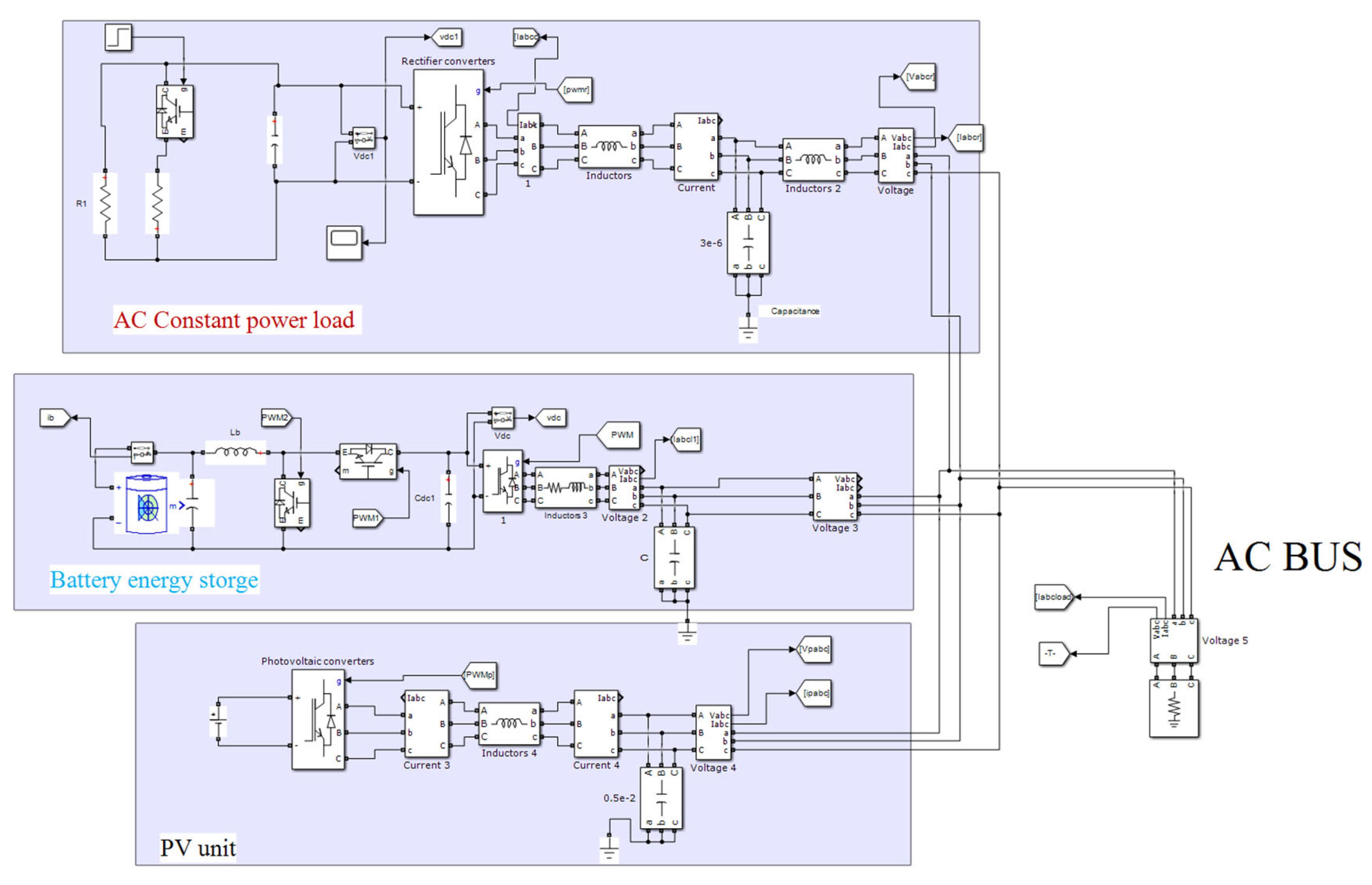
5.1. The Simulation Model of AC Microgrids

Figure 8 is the simulation model of an AC microgrid. The energy storage system is connected to the AC bus through bidirectional DC-DC converters and DC-AC converters. The Buck-Boost converter utilizes continuous current control to maintain a constant battery current, while the AC/DC circuit employs an outside DC voltage control loop and an inner AC current control loop. The charging and discharging states of the battery are determined automatically based on the differences between actual DC voltages and reference value. The rectifier of AC CPL uses a PI control strategy to ensure that the voltage value on both sides of the resistance is constant. Consequently, the active power utilized by AC CPL can be assumed to remain constant. The micro power source is represented by a PV module with a constant output current and closed-loop control. By introducing the step of AC CPL power, large signal interference may be attained. Table 1 displays the AC microgrid simulation model’s parameters.

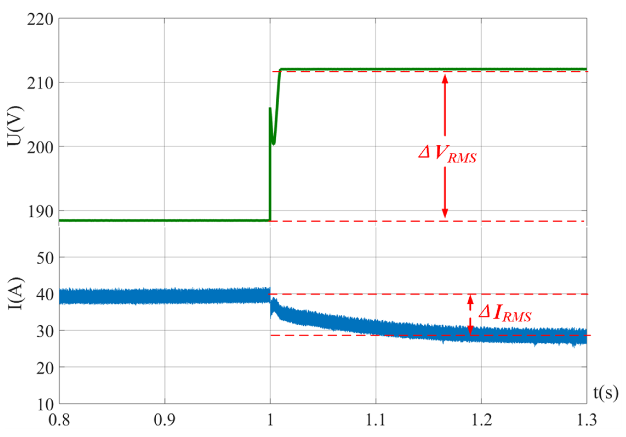
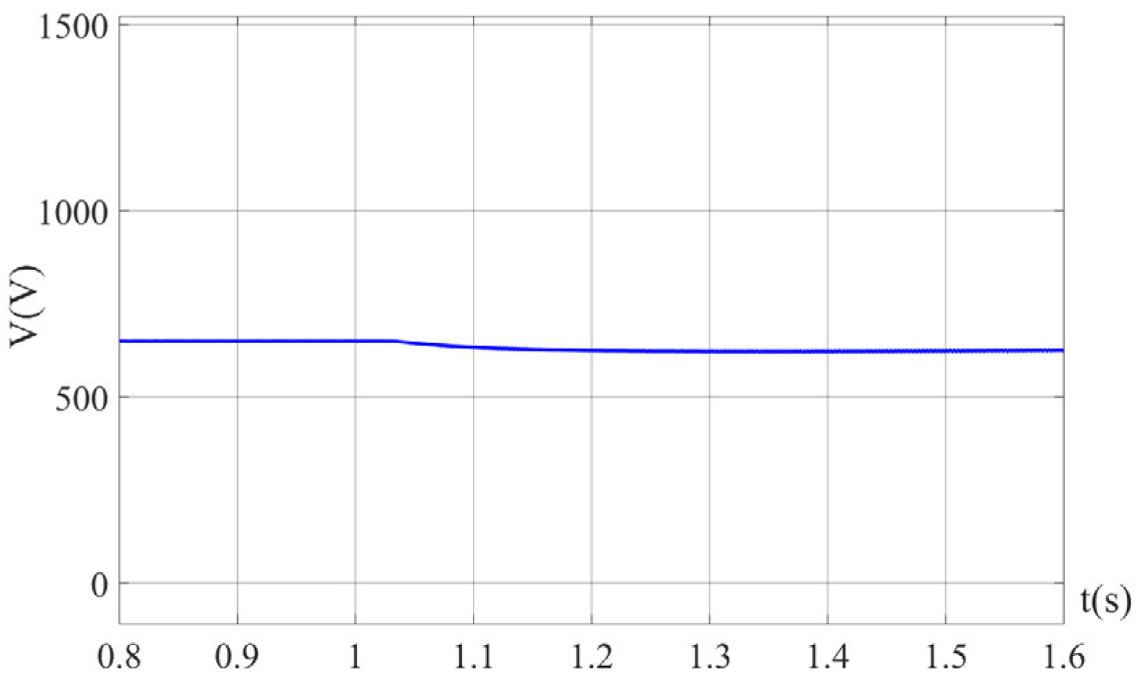
5.2. Stability Control Strategy Verification

According to parameters in Table 1 and stability control strategy in (29), control strategies for energy system stability DC-DC and DC-AC converters in the discharging state are deduced and shown as follows:
R s k i p d L s + P b i d k i p k p d v d c + i d v d v d c 2 c d c > 0 R s k i p d L s < R 1 + P G i 2 2 L 1 P b i d k i p k p d v d c + i d v d v d c 2 c d c < 1 R P V 1 2 C s
The stability control strategy in (34) is simplified as follows:
0.3 < k p d < 1.524
The control strategy in (35) provides the range for the outer voltage loop control parameters kp(d) of the energy storage DC-DC converter and techniques for maintaining system stability in energy systems. In the discharging condition, DC-DC and DC-AC converters are derived and displayed as the following. Similarly, according to parameters in Table 1 and stability control strategy in (33), stability control strategies for energy system DC-DC and DC-AC converters in charging state are deduced and shown as:
R s k i p c L s + k p c v d c R b v b v d c 2 C d c R b v b > 0 R s k i p c L s < R 1 + P G i 2 2 L 1 k p c v d c R b v b v d c 2 C d c R b v b < 1 R P V 1 2 C s
The stability control strategy in (36) is also simplified as follows:
0.3 < k p c < 1.493
The control strategy in (37) determines the range for the outer voltage loop control parameters kp(c) of the energy storage DC-DC converter to ensure a high level of signal stability in the charging stage.
In order to verify the accuracy of obtained (35) and (37), two groups of experiments, A and B, were designed, and the parameters are shown in Table 2. Group A follows the discharging stability control strategy in (35), while Group B does not.
AC CPL power increases from 1 kW to 22.5 kW when t = 1 s. The simulation outcomes for Group A are depicted in Figure 9, Figure 10, Figure 11 and Figure 12. During the large disturbance, the DC bus voltage is still stable at 650 V in Figure 9, the power step of the AC constant power load is shown in Figure 10. And simultaneously, AC bus three-phase voltages and currents could also maintain stability according to Figure 11 and Figure 12. The parameters of Group A conform to the stability criterion proposed in this paper. After experiencing a large disturbance, it will be changed over time to attain the new steady-state equilibrium operating point, as depicted in the figure below:
Group B’s simulation findings are depicted in Figure 13, Figure 14, Figure 15 and Figure 16. Unfortunately, the DC bus voltage oscillates and cannot keep stable during the same power step of AC CPL, as shown in Figure 14. Simultaneously, considerable oscillations appear in the curves of AC bus three-phase voltages and currents based on Figure 15 and Figure 16. It is concluded that the parameter of Group B could not keep AC microgrids stable during large disturbances.
The simulation findings presented in Figure 9, Figure 10, Figure 11, Figure 12, Figure 13, Figure 14, Figure 15 and Figure 16 demonstrate that energy storage converters employing the proposed stability control methodologies could maintain the stability of AC microgrids during major shocks. On the contrary, under the same disturbances, energy storage converters do not follow stability control strategies leading to AC microgrid instability. These results prove the correctness of derived stability control strategies in (29) and (33).

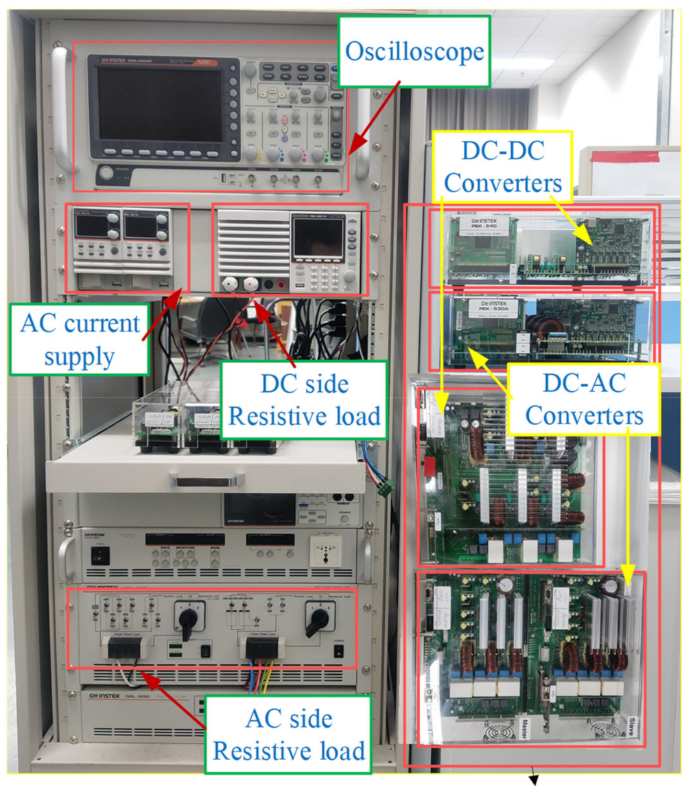
6. Experimental Results

On the basis of the premise depicted in Figure 1, a model of an AC microgrid is developed to validate the stability control strategies derived for energy storage converters in (29) and (33).
The energy storage system is coupled to the AC bus via bidirectional DC-DC and DC-AC converters, with DSP-TMS320F28335 serving as the controller of the converters, as shown in Figure 17. The DC-DC converter uses constant current control technology to maintain constant battery current. The charging and discharging states of a battery are automatically determined by comparing the actual DC voltage to a reference value. According to coordinate transformation, the DC-AC converter utilizes a droop controller to achieve reference voltages and uses outer DC voltage control and inner AC current control methods. The rectifier of AC CPL uses a PI control strategy to ensure that the voltage value on both sides of the resistance is constant. Therefore, it can be approximated that the active power consumed by AC CPL is also constant.
The input micro power supply is an AC power supply. Large signal interference can be achieved by introducing the step of AC CPL power. The AC microgrid’s parameters are listed in Table 3.

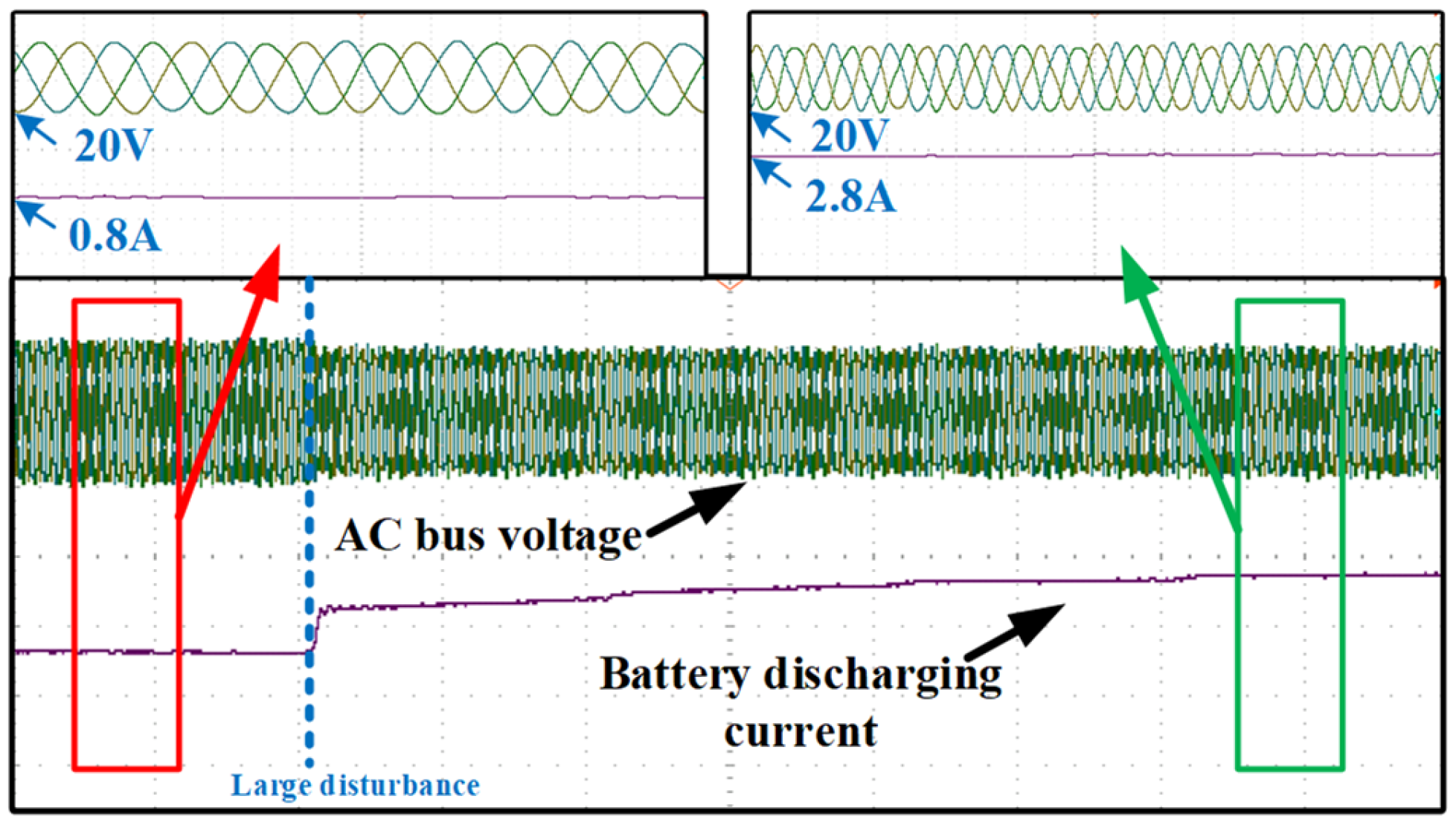
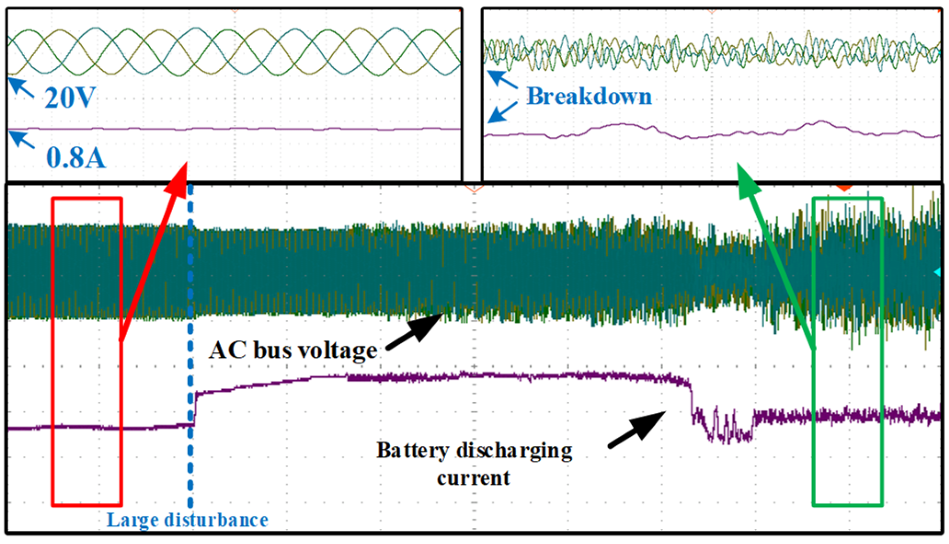
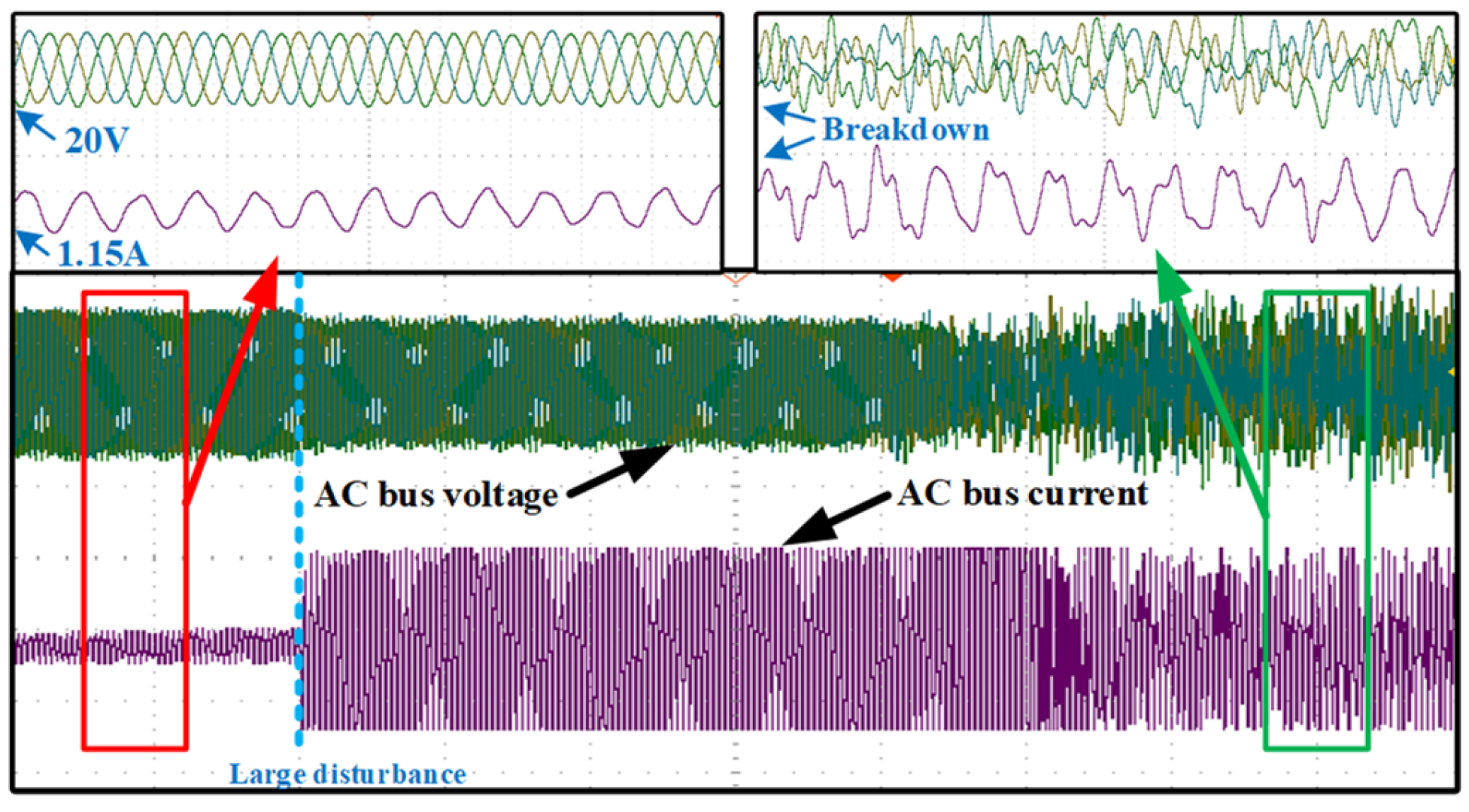
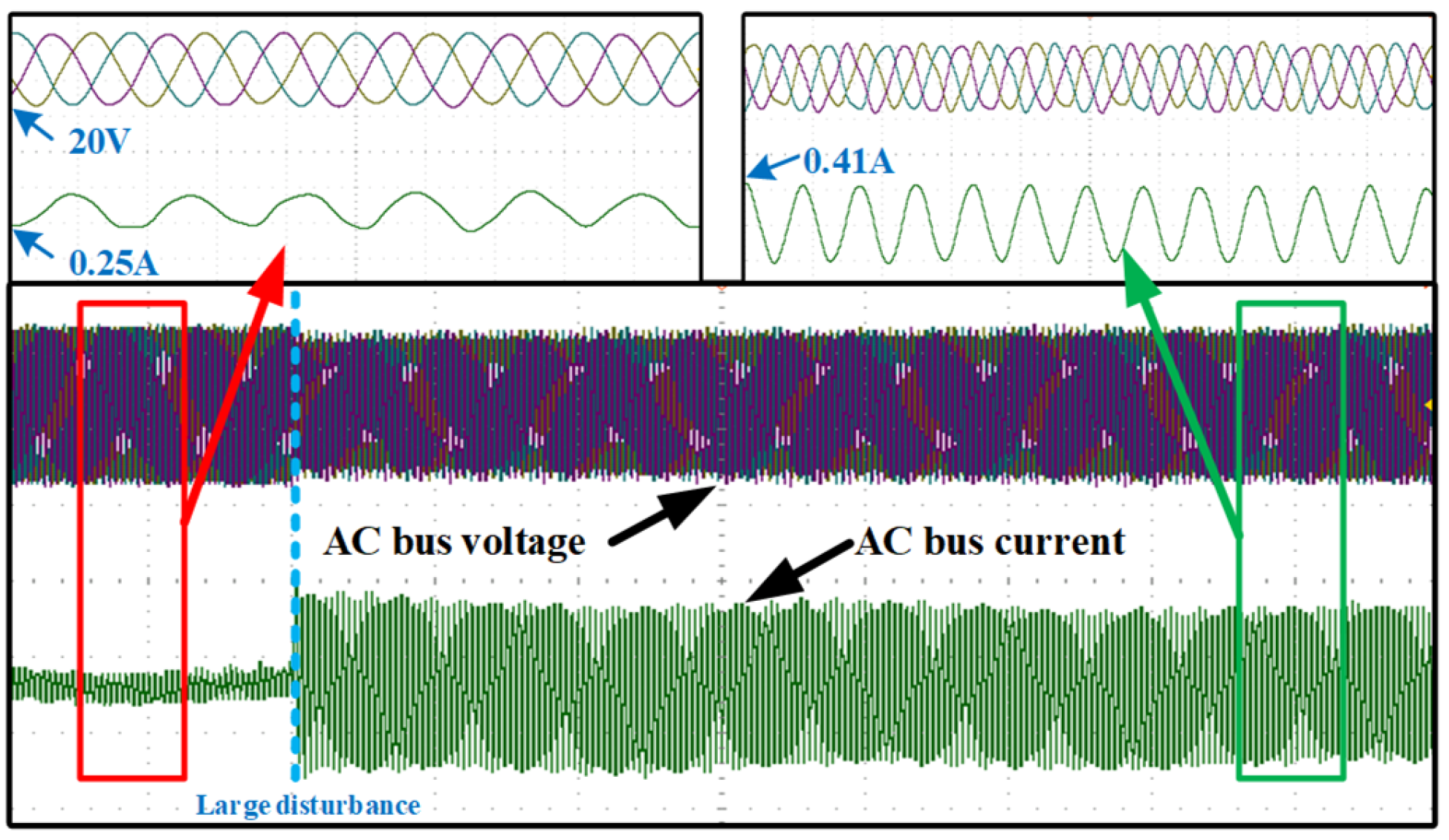
6.1. Discharging Stability Control Strategy Verification of Energy Storage Converters

According to the parameters in Table 3, stability control strategies for energy storage converters in (29) are calculated as follows:
R s k i p d L s + P b i d k i p 2 k p d v d c + i d v d v d c 2 c d c > 0 P b i d k i p 2 k p d v d c + i d v d v d c 2 c d c < 1 R P V 1 2 C s
The inner current loop control parameters kip(d) of the DC/AC converter is determined as 0.06, and (38) is transformed as:
0.078 < k p d < 3.054
The control strategy in (39) provides the range for the outer voltage loop control parameters kp(d) of the energy storage DC-DC converter to guarantee large signal stability in discharging state.
In order to verify the accuracy of the obtained stability control strategy in (39), two groups are designed, as shown in Table 4, and experiments are conducted under the same disturbances. Group A follows the discharging stability control strategy in (39), while Group B does not. The same disruptions are introduced by power steps ranging from 20 W to 120 W for the AC CPL.
The experimental results of Group A are shown in Figure 18 and Figure 19. When AC CPL power steps from 20 W to 120 W, AC bus voltage remains stable at 20 V after a small fluctuation, and the battery discharging current increases with the power step and gradually stabilizes at 2.5 A. Due to the power increase, AC bus effective current grows from 1.15 A to 4.04 A. Experimental results in Figure 18 and Figure 19 indicate parameters of Group A could guarantee AC microgrids’ stability amid significant disturbances.
The experimental outcomes of Group B are depicted in Figure 20 and Figure 21. When AC CPL power steps from 20 W to 120 W, AC bus voltage oscillates greatly and deviates from 20 V. Simultaneously, after power steps, the battery discharging current cannot maintain constant output, and distortion occurs in AC bus current curves. Experimental results in Figure 20 and Figure 21 illustrate the parameters of Group B, and it will be adjusted for a period of time but cannot reach a new steady-state equilibrium operating point.
Figure 18, Figure 19, Figure 20 and Figure 21 indicate that in discharging state, energy storage converters following the proposed stability control strategy in (29) could insure AC microgrid stability during large disturbances. Unfortunately, under these disturbances, energy storage converters that do not follow stability control strategies result in AC microgrid instability. Experimental results certify the correctness of the derived stability control strategy in (29).

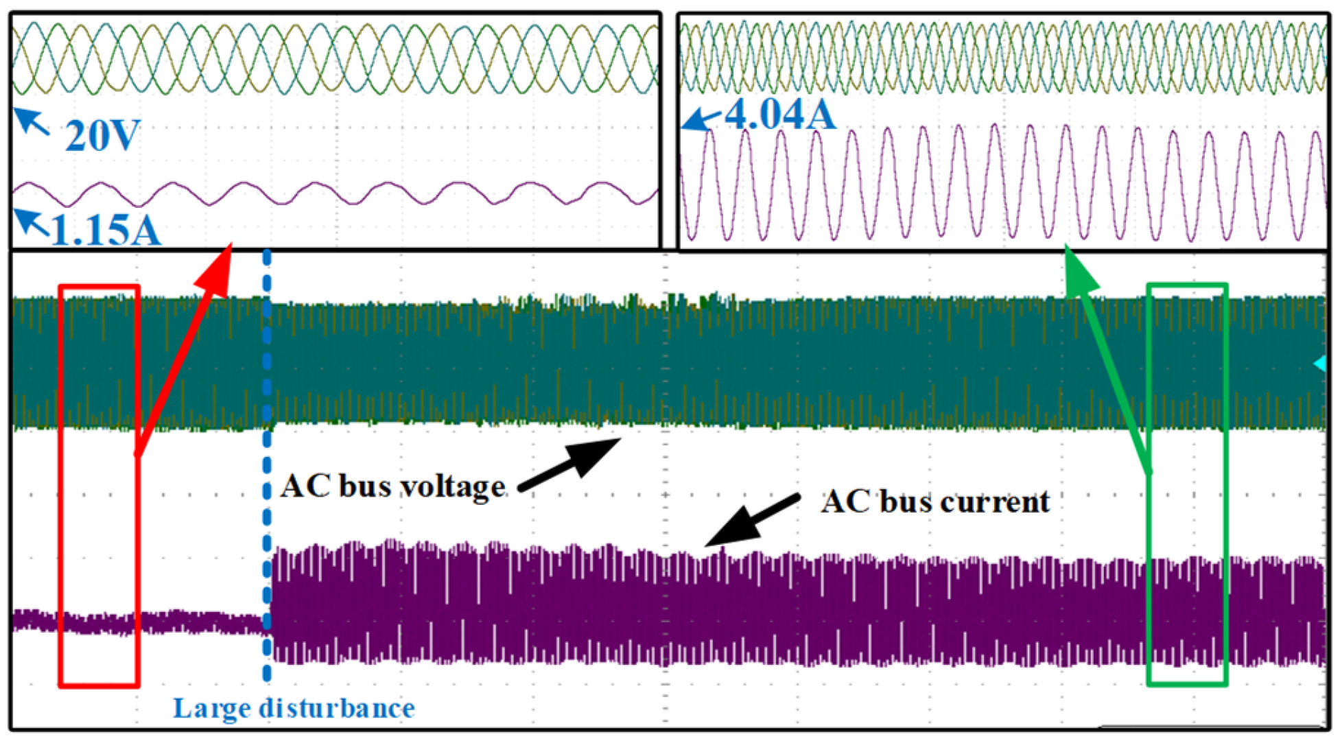
6.2. Charging Stability Control Strategy Verification of Energy Storage Converters

According to the parameters in Table 3, the stability control strategy of (33) in the charging state is adopted, and the constraints of the DC-DC converter charging control parameter are shown as:
R s k i p c L s + k p c v d c R b v b v d c 2 C d c R b v b > 0 1 R P V 1 2 C s > k p c v d c R b v b v d c 2 C d c R b v b
The range for the outer voltage loop control parameter is determined as follows:
0.043 < k p c < 1.197
In order to verify the validity of the obtained stability control strategy in (41), two groups are also designed, as shown in Table 5, and experiments are conducted under the same disturbances. Group C follows discharging stability control strategy in (41), while Group D does not. The AC CPL forms a large disturbance to the system through a power step of 20–87 W.
The experimental findings obtained by Group C are depicted in Figure 22, respectively. The AC bus voltage remains constant at 20 volts after a slight fluctuation, and the AC bus current increases from 0.25 amps to 0.41 amps when the power increases from 20 watts to 87 watts. The parameters shown in Figure 22 belong to Group C and have the potential to keep AC microgrids stable even in the face of significant disturbances.
After increasing the AC CPL power from 20 W to 87 W, the experimental findings of Group D are depicted in Figure 23. AC bus voltage oscillates sharply, and simultaneously, AC bus current distorts seriously. Figure 23 illustrates the parameters of Group D, producing the whole system breakdown during large disturbances.
Comparing Figure 22 with Figure 23, in the charging state, energy storage converters following the proposed stability control strategy in (33) could insure AC microgrid stability after large disturbances. On the contrary, energy storage converters that do not follow stability control strategies result in AC microgrid instability under these disturbances. Experimental findings confirm the validity of the proposed stability control technique in (33).
Based on experimental results from Figure 18, Figure 19, Figure 20, Figure 21, Figure 22 and Figure 23, stability control strategies for energy storage converters in (29) and (33) could guarantee AC microgrid large signal stability under disturbances.

7. Conclusions

This paper derives stability control strategies for bidirectional energy storage converters of islanded AC microgrids, and the characteristics of AC CPLs are taken into account. Through DQ coordinate transformation, the simplified nonlinear models of AC microgrids are established separately when the energy storage system is in charging and discharging states. On the basis of mixed potential theory, large signal models are built, and stability control strategies are proposed. The control strategies also reveal the positive stability influence of energy storage systems and micro power source and the negative stability influence of AC CPLs. According to the control strategies, regulating the outer voltage loop control parameters kp of the energy storage DC/DC converter and the inner current loop control parameters kip of the DC/AC converter significantly increases the large signal stability of islanded AC microgrids without extra equipment. Simulation and experimental results indicate the deduced stability control strategies of energy storage converters could guarantee that AC microgrids are stable when the powers of AC CPLs vary sharply.
In summary, the stability control strategies offer an important design basis for storage system converter control parameters and are very simple and easily implemented. When planning an islanded AC microgrid, increasing the DC side capacitor Cdc and decreasing AC side filter inductor Ls could improve the system’s large signal stability. Simultaneously, when the AC CPLs power of an existing islanded AC microgrid is much larger than the rated power, adjusting the control parameters of the energy storage system mostly guarantees the system’s large signal stability.

Author Contributions

Study design, Literature search, Manuscript writing, X.L.; Graph production, Data analysis, Data processing, S.W.; Supervision; Resources, review and editing, X.S.; Translation, Literature search, J.Z.; All authors have read and agreed to the published version of the manuscript.

Funding

National Key R&D Program of China:KM201910009010; Beijing High-Level Innovation Team Building Plan, Grant/Award Number: IDHT20180502.

Conflicts of Interest

The authors declare no conflict of interest.

References

  1. Sahoo, S.K.; Sinha, A.; Kishore, N. Control Techniques in AC, DC, and Hybrid AC–DC Microgrid: A Review. IEEE J. Emerg. Sel. Top. Power Electron. 2018, 6, 738–759. [Google Scholar] [CrossRef]
  2. Khayat, Y.; Shafiee, Q.; Heydari, R.; Naderi, M.; Dragicevic, T.; Simpson-Porco, J.W.; Dorfler, F.; Fathi, M.; Blaabjerg, F.; Guerrero, J.M. On the Secondary Control Architectures of AC Microgrids: An Overview. IEEE Trans. Power Electron. 2020, 35, 6482–6500. [Google Scholar] [CrossRef]
  3. Kabalan, M.; Singh, P.; Niebur, D. Large Signal Lyapunov-Based Stability Studies in Microgrids: A Review. IEEE Trans. Smart Grid 2017, 8, 2287–2295. [Google Scholar] [CrossRef]
  4. Han, H.; Hou, X.; Yang, J.; Wu, J.; Su, M.; Guerrero, J.M. Review of Power Sharing Control Strategies for Islanding Operation of AC Microgrids. IEEE Trans. Smart Grid 2016, 7, 200–215. [Google Scholar] [CrossRef] [Green Version]
  5. Liu, Z.; Liu, J.; Bao, W.; Zhao, Y. Infinity-Norm of Impedance-Based Stability Criterion for Three-Phase AC Distributed Power Systems with Constant Power Loads. IEEE Trans. Power Electron. 2015, 30, 3030–3043. [Google Scholar] [CrossRef]
  6. Xu, X.; Liu, Q.; Zhang, C.; Zeng, Z. Prescribed Performance Controller Design for DC Converter System with Constant Power Loads in DC Microgrid. IEEE Trans. Syst. Man Cybern. Syst. 2020, 50, 4339–4348. [Google Scholar] [CrossRef]
  7. Herrera, L.; Zhang, W.; Wang, J. Stability Analysis and Controller Design of DC Microgrids with Constant Power Loads. IEEE Trans. Smart Grid 2017, 8, 881–888. [Google Scholar]
  8. Matveev, A.S.; Machado, J.E.; Ortega, R.; Schiffer, J.; Pyrkin, A. A Tool for Analysis of Existence of Equilibria and Voltage Stability in Power Systems with Constant Power Loads. IEEE Trans. Autom. Control 2020, 65, 4726–4740. [Google Scholar] [CrossRef]
  9. Cesar, E.L.; Pagano, D.J.; Pou, J. Bifurcation Analysis of Parallel-Connected Voltage-Source Inverters with Constant Power Loads. IEEE Trans. Smart Grid 2018, 9, 5482–5493. [Google Scholar] [CrossRef]
  10. Xu, Q.; Jiang, W.; Blaabjerg, F.; Zhang, C.; Zhang, X.; Fernando, T. Backstepping Control for Large Signal Stability of High Boost Ratio Interleaved Converter Interfaced DC Microgrids with Constant Power Loads. IEEE Trans. Power Electron. 2020, 35, 5397–5407. [Google Scholar] [CrossRef]
  11. Sadabadi, M.S.; Shafiee, Q. Scalable Robust Voltage Control of DC Microgrids with Uncertain Constant Power Loads. IEEE Trans. Power Syst. 2020, 35, 508–515. [Google Scholar] [CrossRef]
  12. Xu, Q.; Zhang, C.; Wen, C.; Wang, P. A Novel Composite Nonlinear Controller for Stabilization of Constant Power Load in DC Microgrid. IEEE Trans. Smart Grid 2019, 10, 752–761. [Google Scholar] [CrossRef]
  13. Vafamand, N.; Khooban, M.H.; Dragicevic, T.; Blaabjerg, F.; Boudjadar, J. Robust Non-Fragile Fuzzy Control of Uncertain DC Microgrids Feeding Constant Power Loads. IEEE Trans. Power Electron. 2019, 34, 11300–11308. [Google Scholar] [CrossRef]
  14. Chen, J.; Chen, J. Stability Analysis and Parameters Optimization of Islanded Microgrid with Both Ideal and Dynamic Constant Power Loads. IEEE Trans. Ind. Electron. 2018, 65, 3263–3274. [Google Scholar] [CrossRef]
  15. Hossain, E.; Perez, R.; Nasiri, A.; Padmanaban, S. A Comprehensive Review on Constant Power Loads Compensation Techniques. IEEE Access 2018, 6, 33285–33305. [Google Scholar] [CrossRef]
  16. Liu, Q.; Caldognetto, T.; Buso, S. Review and Comparison of Grid-Tied Inverter Controllers in Microgrids. IEEE Trans. Power Electron. 2020, 35, 7624–7639. [Google Scholar] [CrossRef]
  17. Gupta, A.; Doolla, S.; Chatterjee, K. Hybrid AC–DC Microgrid: Systematic Evaluation of Control Strategies. IEEE Trans. Smart Grid 2018, 9, 3830–3843. [Google Scholar] [CrossRef]
  18. Areerak, K.; Sopapirm, T.; Bozhko, S.; Hill, C.I.; Suyapan, A.; Areerak, K. Adaptive Stabilization of Uncontrolled Rectifier Based AC–DC Power Systems Feeding Constant Power Loads. IEEE Trans. Power Electron. 2018, 33, 8927–8935. [Google Scholar] [CrossRef]
  19. Karimipour, D.; Salmasi, F. Stability Analysis of AC Microgrids with Constant Power Loads Based on Popov’s Absolute Stability Criterion. IEEE Trans. Circuits Syst. II Express Briefs 2015, 62, 696–700. [Google Scholar] [CrossRef]
  20. Sulligoi, G.; Bosich, D.; Giadrossi, G.; Zhu, L.; Cupelli, M.; Monti, A. Multiconverter Medium Voltage DC Power Systems on Ships: Constant-Power Loads Instability Solution Using Linearization via State Feedback Control. IEEE Trans. Smart Grid 2014, 5, 2543–2552. [Google Scholar] [CrossRef]
  21. Chang, F.; Cui, X.; Wang, M.; Su, W.; Huang, A.Q. Large-Signal Stability Criteria in DC Power Grids with Distributed-Controlled Converters and Constant Power Loads. IEEE Trans. Smart Grid 2020, 11, 5273–5287. [Google Scholar] [CrossRef]
  22. Lin, P.; Jiang, W.; Wang, J.; Shi, D.; Zhang, C.; Wang, P. Toward Large-Signal Stabilization of Floating Dual Boost Converter-Powered DC Microgrids Feeding Constant Power Loads. IEEE J. Emerg. Sel. Top. Power Electron. 2021, 9, 580–589. [Google Scholar] [CrossRef]
  23. El Aroudi, A.; Haroun, R.; Al-Numay, M.S.; Calvente, J.; Giral, R. Fast-Scale Stability Analysis of a DC–DC Boost Converter with a Constant Power Load. IEEE J. Emerg. Sel. Top. Power Electron. 2021, 9, 549–558. [Google Scholar] [CrossRef]
  24. Hassan, M.A.; He, Y. Constant Power Load Stabilization in DC Microgrid Systems Using Passivity-Based Control with Nonlinear Disturbance Observer. IEEE Access 2020, 8, 92393–92406. [Google Scholar] [CrossRef]
  25. Valinejad, J.; Marzband, M.; Korkali, M.; Xu, Y.; Al-Sumaiti, A.S. Coalition Formation of Microgrids with Distributed Energy Resources and Energy Storage in Energy Market. J. Mod. Power Syst. Clean Energy 2020, 8, 906–918. [Google Scholar] [CrossRef]
  26. Tian, L.; Cheng, L.; Guo, J.; Wu, K. System Modeling and Optimal Dispatching of Multi-energy Microgrid with Energy Storage. J. Mod. Power Syst. Clean Energy 2020, 8, 809–819. [Google Scholar] [CrossRef]
  27. Weiss, L.; Mathis, W.; Trajkovic, L. A generalization of Brayton-Moser’s mixed potential function. IEEE Trans. Circuits Syst. I Fundam. Theory Appl. 1998, 45, 423–427. [Google Scholar] [CrossRef] [Green Version]
  28. Xu, J.; Hu, Y.; Qian, H.; Xie, S. Delay-Based Phase-Locked Loop Parameters Design Based on Stability Region of Grid-Connected Single-Phase Inverter Under Grid Voltage Sags. IEEE Trans. Ind. Electron. 2022, 69, 11324–11334. [Google Scholar] [CrossRef]
  29. Rao, T.S.M.; Anuradha, T.; Kaur, U.; Rajan, M.S.; Patnala, T.R.; Kumar, V.R. Machine Learning for the Assessment of Transient Stability of Power Systems. In Proceedings of the 2022 6th International Conference on Intelligent Computing and Control Systems (ICICCS), Madurai, India, 25–27 May 2022; pp. 1238–1242. [Google Scholar]
  30. Mourinho, F.A.; Assis, T.M.L. A new approach to retrofit plans for distributed energy resources to mitigate adverse impacts on bulk power systems stability. IEEE Lat. Am. Trans. 2022, 20, 669–676. [Google Scholar] [CrossRef]
  31. Spanias, C.; Aristidou, P.; Michaelides, M. A Passivity-Based Framework for Stability Analysis and Control Including Power Network Dynamics. IEEE Syst. J. 2021, 15, 5000–5010. [Google Scholar] [CrossRef]
  32. Zhou, W.; Wang, Y.; Enrique, T.R.; Zhe, C. Effect of Reactive Power Characteristic of Offshore Wind Power Plant on Low-Frequency Stability. IEEE Trans. Energy Convers. 2020. [Google Scholar] [CrossRef] [Green Version]
  33. Alsakati, A.A.; Vaithilingam, C.A.; Alnasseir, J.; Jagadeeshwaran, A. Transient Stability Improvement of Power System using Power System Stabilizer Integrated with Excitation System. In Proceedings of the 2021 11th IEEE International Conference on Control System, Computing and Engineering (ICCSCE), Penang, Malaysia, 27–28 August 2021; pp. 34–39. [Google Scholar] [CrossRef]
  34. Plesnick, S.; Singh, P. A New Impedance-based Relative Stability Criterion for DC Power Systems. In Proceedings of the 2020 52nd North American Power Symposium (NAPS), Tempe, AZ, USA, 11–13 April 2021; pp. 1–6. [Google Scholar] [CrossRef]
  35. Liang, Y.L.; Li, K.J.; Ma, Z.; Lee, W.J. Typical Fault Cause Recognition of Single-Phase-to-Ground Fault for Overhead Lines in Nonsolidly Earthed Distribution Networks. In IEEE Transactions on Industry Applications; IEEE: Piscataway, NJ, USA, 2020; Volume 56, pp. 6298–6306. [Google Scholar]
  36. Li, Y.; Tang, G.; Ge, J.; He, Z.; Pang, H.; Yang, J.; Wu, Y. Modeling and damping control of modular multilevel converter based DC grid. IEEE Trans. Power Syst. 2018, 33, 723–735. [Google Scholar] [CrossRef]
  37. Amin, M.; Molinas, M.; Lyu, J.; Cai, X. Impact of Power Flow Direction on the Stability of VSC-HVDC Seen From the Impedance Nyquist Plot. IEEE Trans. Power Electron. 2017, 32, 8204–8217. [Google Scholar] [CrossRef]
Figure 1. The schematic of an islanded AC microgrid.
Electronics 12 01067 g001
Figure 2. The RMS voltage and current of an AC CPL.
Electronics 12 01067 g002
Figure 3. Control principles of energy storage Buck-Boost converter.
Electronics 12 01067 g003
Figure 4. Control principles of energy storage DC-AC converter.
Electronics 12 01067 g004
Figure 5. The converter’s model in the dq synchronous rotating coordinate system (the vector E of the grid electromotive force as the reference direction).
Electronics 12 01067 g005
Figure 6. Nonlinear model of AC microgrid in discharge state.
Electronics 12 01067 g006
Figure 7. Nonlinear model of AC microgrid in charging state.
Electronics 12 01067 g007
Figure 8. The simulation mode l of AC microgrids.
Electronics 12 01067 g008
Figure 9. The DC bus side voltage (Group A).
Electronics 12 01067 g009
Figure 10. AC constant power load generates a power step (Group A).
Electronics 12 01067 g010
Figure 11. Three-phase voltages of AC bus (Group A).
Electronics 12 01067 g011
Figure 12. Three-phase currents of AC bus (Group A).
Electronics 12 01067 g012
Figure 13. The DC bus side voltage (Group B).
Electronics 12 01067 g013
Figure 14. AC constant power load generates a power step (Group B).
Electronics 12 01067 g014
Figure 15. Three-phase voltages of AC bus (Group B).
Electronics 12 01067 g015
Figure 16. Three-phase currents of AC bus (Group B).
Electronics 12 01067 g016
Figure 17. The prototype of an AC microgrid.
Electronics 12 01067 g017
Figure 18. The curves of AC bus voltages and battery discharging current (Group A).
Electronics 12 01067 g018
Figure 19. The curves of AC bus voltages and currents in discharging state (Group A).
Electronics 12 01067 g019
Figure 20. The curves of AC bus voltages and battery discharging current (Group B).
Electronics 12 01067 g020
Figure 21. The curves of AC bus voltages and currents in discharging state (Group B).
Electronics 12 01067 g021
Figure 22. The curves of AC bus voltages and currents in the charging state (Group C).
Electronics 12 01067 g022
Figure 23. The curves of AC bus voltages and currents in the charging state (Group D).
Electronics 12 01067 g023
Table 1. Parameters of AC microgrid simulation model.
ParametersValue
AC bus voltage—Vs311 V
DC-DC converter high voltage—vdc650 V
Battery voltage—vb430 V
AC side filter inductor—Ls0.0007 H
AC side filter capacitor—Cs100 μF
DC side capacitor—Cdc800 μF
DC-AC converter voltage outer loop proportional link coefficient—kvp10
DC-AC converter voltage outer loop integral link coefficient—kvi100
DC-AC converter current outer loop proportional link coefficient—kip0.1
DC-AC converter current outer loop integral link coefficient—kii100
Sag coefficient-m,n 1 × 10 5 , 3 × 10 4
Output power of PV unit—PG30 kW
Initial power of AC constant power load—P11–22.5 kW
Resistive load power—Pr20 kW
Table 2. Comparison parameters of experiments in groups A and B.
GroupAB
Outer voltage loop control parameters in discharging state—kp(d)10.5
Outer voltage loop control parameters in charging state—kp(c)1
Power steps of AC CPL1–22.5 kW
Following stability control strategyYESNO
Table 3. Parameters of the AC microgrid prototype.
ParametersValue
AC side filter capacitor—Cs3 × 10−4 F
AC side filter inductor—Ls2.5 × 10−3 H
AC side filter inductor equivalent resistance—Rs0.318 Ω
Micro source output power—PG40 W
Battery current—i22.5 A
DC side capacitor—Cdc2 × 10−4 F
Voltage of DC side capacitor—vdc60 V
Battery voltage—vb50 V
Battery output power—Pb125 W
Table 4. Experimental platform parameters for groups A and B in the discharged condition.
GroupAB
Outer voltage loop control parameters in discharging state—kp(d)0.14
Power steps of AC CPL20–120 W
Following stability control strategyYESNO
Table 5. Experimental platform parameters for groups C and D in the charging condition.
GroupCD
Outer voltage loop control parameters in discharging state kp(c)0.11.35
Power steps of AC CPL20–87 W
Following stability control strategyYESNO
Disclaimer/Publisher’s Note: The statements, opinions and data contained in all publications are solely those of the individual author(s) and contributor(s) and not of MDPI and/or the editor(s). MDPI and/or the editor(s) disclaim responsibility for any injury to people or property resulting from any ideas, methods, instructions or products referred to in the content.

