Abstract
This study presents the use of a vision-based fuzzy-PID lane-keeping control system for the simulation of a single-track bicycle model. The lane-keeping system (LKS) processes images to identify the lateral deviation of the vehicle from the desired reference track and generates a steering control command to correct the deviation. The LKS was compared to other lane-keeping control methods, such as Ziegler–Nichols proportional derivative (PD) and model predictive control (MPC), in terms of response time and settling time. The fuzzy-PID controller had the best performance, with fewer oscillations and a faster response time compared to the other methods. The PD controller was not as robust under various conditions due to changing parameters, while the MPC was not accurate enough due to similar reasons. However, the fuzzy-PID controller showed the best performance, with a maximum lateral deviation of 2 cm, a settling time of 12 s, and Kp and Kd values of 0.01 and 0.06, respectively. Overall, this work demonstrates the potential of using fuzzy-PID control for effective lane recognition and lane-keeping in vehicles.
1. Introduction
Autonomous vehicles are controlled through either of the following means: by the use of sensors, Global Positioning System (GPS) synchronization, and cameras. One of the most common areas of interest in research for autonomous cars is active safety systems, such as the advanced driver assistance system (ADAS). Examples of ADAS systems are lane-keeping assist (LKA) and lane departure warning (LDW) to mention just a few. For the LKA using vision-based techniques in the development stage of an autonomous vehicle’s lane-detecting/keeping algorithm, the approach will only be effective on marked lanes. However, one of the setbacks still under investigation is the process of localizing a vehicle in real-time for unmarked lanes or road boundaries. Some of the available common libraries in either MATLAB or OpenCV do not even have adaptive functions for detecting unmarked lanes or boundaries, or even sharp curves, except for some shapes, such as circles, ellipses, etc., which already have pre-defined functions in the common libraries used for processing [1]. A further review also revealed that the use of color thresholding for lane detection can be a terrible idea because it is not robust enough to detect discontinuity in lanes or noise present on the lanes, such as cast shadows and illumination and disturbances [2].
Typically, the detection of involuntary lane departures in commercial lane-keeping assist systems (LKASs) is based on time to line crossing (TLC) [3]. It works by projecting the trajectory of the vehicle by using time and dynamics to project how and when the vehicle will arrive at the lane markings.
The computation of TLC could be arrived at in certain ways depending on the shape/contour of the road and the conditions surrounding the making of the vehicle model. A major disadvantage of TLC-based LKASs is the false alarms they raise owing to previously set required thresholds [4]. Alternatively, lane departures can be predicted by maneuver recognition algorithms. The benefits of this are dual-pronged; first, no threshold is required; second, with time, they adapt to a specific driver’s style based on data accrued. Therefore, in terms of reliability, lane departure prediction tends to take the lead/perform better [5]. Several lane detection techniques exist and are classified as either vision-based or framework-based. Some framework-based techniques are robust and have a high cost of setup and development, such as LIDAR and magnetic sensors, as seen in [6]. The vision-based technique has a camera mounted on the vehicle, is cheaper, and owes greater advantage to lane recognition in both existent and non-existent lane markings [7].
Among the various advanced driver assistance systems that exist are LKASs, which came into existence a decade ago and are fast gaining popularity even in passenger cars. They function by sensors that are both exteroceptive and proprioceptive to forestall lane departures on highways that occur involuntarily by either actively taking over the control of the vehicle or warning the driver [3]. Ref. [8] believed that, in actively controlling a car, it is crucial to define a safe transition of control from the driver to the controller. The early detection of involuntary lane departures is necessary to ensure less evasive inputs by the controller. Over the years, researchers have proposed many control approaches. Ref. [9] described an efficient lane-change maneuver control system for platoons of vehicles. The problem of the combined longitudinal and lateral control of a platoon of non-identical vehicles on a curved lane of a highway was presented in the design and experimental implementation of an integrated longitudinal and lateral control system for the operation of automated vehicles in platoons.
However, it was gathered from the literature that lane-keeping control is more effective when using lane detection [10,11], since the various studies used predictive measures for unintentional lane departure on the various trajectories. This method is not fully accurate because none of their studies could place or localize the vehicle at a given point in time, hence the lane detection method. Lane detection is a vital task in the development of lane-keeping systems. It involves the positioning of the vehicle coordinates on the road and is the process of locating lane markers on the road and then presenting these locations to an intelligent system. According to [12], intelligent vehicles cooperate with smart infrastructure to achieve a safer environment and better traffic conditions.
Lane detection is a vital task in the development of lane-keeping systems, similar to how thermal management and marine environment interference are important for controlling unmanned surface vessels and fuel cells, respectively. As seen in references [13] and [14], the use of control methods such as the diploid genetic algorithm and fuzzy-PID controller and S-plane adaptive control algorithm can improve the adaptability and robustness of these systems.
Previous studies, such as [15], have emphasized the importance of developing smaller and more efficient algorithms for the task of autonomous driving. This study primarily focused on the areas of lane-keeping control systems and steering angle prediction. Additionally, this study highlighted the importance of developing environmentally friendly algorithms for the task of autonomous driving. This is a crucial aspect to consider in the field of autonomous driving, as it not only allows for more efficient and cost-effective solutions, but also promotes sustainability.
The applications of a lane-detecting system could be as simple as pointing out lane locations to the driver on an external display or more complex tasks, such as predicting a lane change in the instant future to avoid collisions with other vehicles. Some of the interfaces used to detect lanes include cameras, laser range images, LIDAR, and GPS devices.
2. Kinematic Model of Lateral Vehicle Motion
Certain assumptions were made for the development of a vehicle’s lateral motion, which will be mentioned in the course of this study. The equations of motion describe mathematically the vehicular path without paying attention to the forces acting on it. The bicycle model is used to handle the lateral dynamics of four-wheel vehicles, represented by two-wheel vehicles [16]. The formulation simplifies the derivative of the equation by taking out the dynamics of roll and pitch (which may be significant), and it produces equations that are implementable. The model works by linearizing the system in small angle assumptions corresponding to the linear coefficient of the forces generated by the tires. The model is assumed to maintain a constant velocity.
A vehicle’s lateral dynamic Is simplified by treating it as a bicycle that does not experience pitch or roll and travels at a uniform speed. For this purpose, the equations for the front wheels are mathematically merged to form a single wheel and likewise for the rear. By ignoring the vehicle’s roll, bounce, and pitch, a vehicle model with three degrees of freedom, yaw, and planar motion can be produced [17].
Where the vehicle experiences less than 0.3 g’s, earlier works confirm that this model is accurate [18]. The results produced in situations where higher g’s are experienced using the bicycle model yield inaccurate results. Research exposed the dearth of literature outlining the vehicle dynamics of autonomous navigation problems. It is on record that the National Robotics Engineering Center’s CRUSHER made several attempts in the past to use machine learning techniques to aid in terrain traversal but, being a military program, it is highly confidential limiting its availability to the public [19]. BMW and Volkswagen (both German auto manufacturers) have carried out high-performance autonomous driving on learned courses but have not made the results easily accessible [20].
The state equation of the developed model is a linear single input to output system of the single input variable, the steering wheel angle, and two output variables, the lateral deviation and the steering angle. From Figure 1, in applying Newton’s second law of motion, the dynamic model employs the vehicle’s center of gravity as the reference point.
where Equation (1) is also known as the moment Mz.
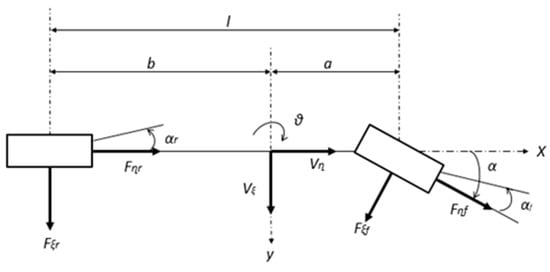
Figure 1.
Illustration of single tracked bicycle model of vehicle handling characteristics as derived by [15].
m = total mass, ψ = yaw rate, r = side slip, u = vehicle velocity, and Fyf + Fyr are both front and rear wheel forces.
Yaw dynamic is described when equilibrium is obtained about the z axis and is considered as follows:
where Iz τ is the vehicle’s inertia, a is the distances from the front axle to the center, and b is the distances from the rear axle to the center of mass.
From Figure 1, resolving the forces to obtain the velocity at the rear, we obtain the following:
where v is the lateral velocity.
Assuming that tan αr = αr, therefore, Equation (3) can now be rewritten as follows:
Moreover, assuming the vehicle is taking a turn and its turning radius is denoted by r.
where is the vehicle slip angle and is the steering angle
By simplifying and rearranging both Equations (5) and (6), we obtain the following:
The steering angle now becomes
where L is the sum of both a and b considering the tire model for this bicycle model given by
where Ca is the tire cornering stiffness.
So, for the front and rear wheels, we have
Caf is the cornering stiffness of the front axle and Car is the cornering stiffness of rear axle. The sum of Equations (10) and (11) will then be given as
Substituting Equations (5) and (6) into Equation (11), we obtain the following:
Moreover, Equation (1) now becomes
Using the state space for both Equations (12) and (13) can be written as
where A is the state matrix and B is the input control matrix.
Equation (15) is the state-space form of the bicycle model used for the simulation studies in determining the response of the vehicle at any dynamic input.
3. Methodology
The vision-based process started with capturing the road ahead of the vehicle by using cameras mounted aboard and then pre-processing techniques on the images were carried out. Pre-processing is a term used to describe various processes carried out on the computer to bring out information by converting image data to digital data. The pre-processing steps taken to develop the lane detection involve video/image conversion, where videos are converted to images and smoothing and where they are converted from the original red–green–blue (RGB) format to grayscale format. The conversion is essential for the detection of discontinuities in the video/image that is sharp.
Algorithms of edge detection are used to define the shape of a region and identify objective regions through image recognition and analysis. Image processing relies on them for outlining the target boundary and development of object background. These techniques were applied to the processed image/video. The extraction process is for the detection of possible edge points. An image with automatic thresholds was produced by a suitable edge detector.
A popular technique known as the Hough transform, as seen in [21], was used to isolate features of shapes within the image and used to detect line roads as lane detection. After sending the edged image/video to the line detector, it produces left and right boundary segments. A scan is performed by detecting the Hough lines to produce a lane boundary with serial points on both the left and right. When the data are processed, lane boundaries are produced in the form of pairs of hyperbolas.
The lane-keeping system architecture is depicted in Figure 2.
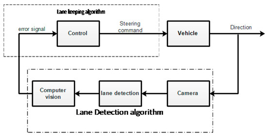
Figure 2.
Block diagram of the lane-keeping system.
For the simulation studies, a lane-keeping system was modeled in Simulink with the following input parameters to the LKS: previewed curvature, vehicle longitudinal velocity, and lateral deviation. The lane-keeping model contains three main segments: lane center estimation, lane detection, and lane-keeping controller.
A subsystem in lane detection sends out an alarm when the vehicle is detected to be too close to the lane, while the function of the estimate lane center is to process the data from lane sensors and transfer them to the lane-keeping controller. The lane-keeping controller controls the steering wheel to ensure the vehicle remains in its lane.
This was made possible by setting the lateral deviation to zero. The lateral deviation error signal is the distance between the vehicle position and the desired reference track at a given point, which is sent to the controller, which then adjusts the steering angle of the control wheel such that the vehicle follows the reference track. The controller constantly works to minimize the distance between the vehicle position and the reference track at every given time. The scenario reader block in Simulink was used to create ideal left and right lane boundaries with respect to the vehicle position for the studies.
4. Control Strategy
The path-tracking control of an autonomous vehicle is one of the most difficult automation challenges because of constraints on mobility, speed of motion, high-speed operation, complex interaction with the environment, and typically a lack of prior information [22]. However, researchers have proposed many control approaches. Ref. [10] described an efficient lane-change maneuver control system for platoons of vehicles. The problem of the combined longitudinal and lateral control of a platoon of non-identical vehicles on a curved lane of a highway was presented in the design and experimental implementation of an integrated longitudinal and lateral control system for the operation of automated vehicles in platoons. Moreover, a review of previous studies showed that various theories and methods have highlighted the use of certain forms of control, which include the PID control method, [23], the predictive control method [24], the fuzzy control method, and the model reference adaptive method [25]. Therefore, the findings from the literature could be summarized as that though controllers such as PID, MPC, and fuzzy logic were used for either the lateral or longitudinal control of the autonomous vehicle, their results still showed some lateral steering control issues, as a result of the changing parameters of the vehicle. A more adaptive system would be able to take care of these changing parameter issues. Since others studies, such as [26], have shown that a fuzzy gain scheduling scheme of PID controllers for process control can give a better performance where fuzzy rules and reasoning are utilized online to determine the controller parameters based on the error signal and its first difference, then this method could be applied for autonomous lane-keeping as a means of solving the changing parameters issues. Fuzzy gain scheduling has been used in other applications and has been found suitable. Thus, the use of this control structure would demonstrate that better control performance can be achieved in comparison with other controls, such as PID and MPC.
5. Discussion of Results
Figure 3 shows the first difference determined by controller-based parameters from fuzzy rules and reasoning demonstrating a better performance in control. The approach was generating controller parameters from fuzzy rules and reasoning.
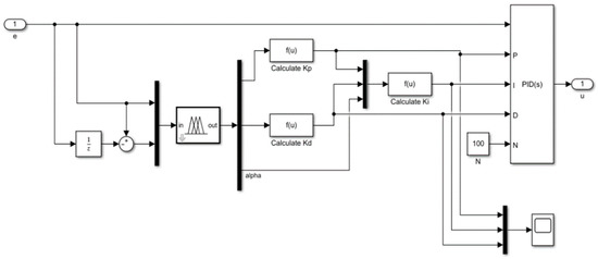
Figure 3.
Simulink Diagram of Fuzzy-PID Control.
A fuzzy controller was used for the computation of the steering control. A fuzzy controller consists of a rule base containing the experts’ procedural knowledge and a variable base containing the different linguistic values that they consider as seen in [27]. The human driver’s procedural knowledge was represented by a fuzzy rule base. The rule base contains the necessary information on how drivers execute their actions to keep the vehicle in its lane. In this instance, the fuzzy rule base was common to all driving tasks because the main objective is to keep the vehicle in its lane, i.e., to minimize the lateral deviation error. Therefore, three rules were used to help keep the vehicle in the lane. These rules stand for basic human driving reasoning: If the vehicle is moving out of the lane to the left, then turn the steering wheel to the right to offset the lateral deviation error. The same thing applies if the deviation is to the right. The membership functions of the input consist of the longitudinal speed, lateral deviation, and preview curvature with fuzzy sets of the speed of fast speed, medium speed, and slow speed. The membership function of the lateral deviation is divided into five fuzzy sets each, which are high positive deviation, medium positive deviation, small deviation, medium negative deviation, and high negative deviation. Finally, the input membership function for preview curvature is highly positive deviation, medium positive deviation, small deviation, medium negative deviation, and high negative deviation, respectively. Moreover, for the output, the membership function is high positive steering angle, medium positive steering angle, small steering angle, medium negative steering angle, and high negative steering angle, as seen in Figure 4, respectively.
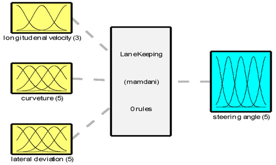
Figure 4.
Fuzzy lane-keeping system architecture.
Based on the fuzzy architecture in Figure 4, fuzzy gain scheduling (FGS) was used for the fuzzy-PID controller. Fuzzy reasoning mechanisms, knowledge-based fuzzy rules, and the conventional PID control system are the main components of this type of Fuzzy-PID controller. The PID controller generates a required steering angle from knowledge-based and fuzzy interference tuned from PID gains online. The simulation was based on the fuzzy rules that were set in the fuzzy algorithm to adjust the steering angle based on the changing parameters, to make the vehicle maintain the desired reference trajectory. This is important because a combination of both Fuzzy and PID would help take care of the changing parameters and would give better performance on dynamic behaviors as seen in other applications with changing parameters.
Performance Analysis of the Fuzzy-PD Controller
Performance analysis was carried out with input constant longitudinal velocities of 10 m/s, 15 m/s, 20 m/s, and 25 m/s for a scaled vehicle. The simulation was conducted and the results are shown in Figure 5.
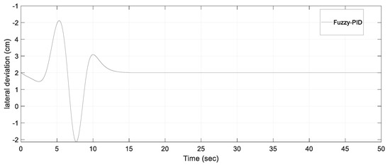
Figure 5.
Performance of the fuzzy-PID controller.
From Figure 5, it can be observed that few over shots are seen. The results showed a remarkable reduction in the overshoot as it guides the vehicle along the trajectory of the reference.
Further analysis of the fuzzy-PID control at different longitudinal velocities was conducted as seen in Figure 6. The results show the performance of fuzzy-PID at different longitudinal velocities. A lateral deviation of −1 cm to 0.5 cm was observed in Figure 6 at a longitudinal velocity of 10 m/s. As the longitudinal velocity was increased from 10 m/s to 15 m/s, it could be observed that the oscillation changed, and a new lateral deviation of −1.2 cm to 0.2 cm was observed with a settling time of 7 s. By further increasing the longitudinal velocity, wider oscillations were seen with shorter settling times.
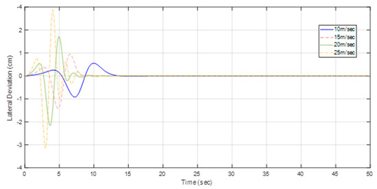
Figure 6.
Performance analysis of the fuzzy-PD controller at various longitudinal velocities.
The performance of fuzzy-PID control was compared with simulated Ziegler–Nichols PD control as seen in Figure 7. From the result, it was observed that although the control strategy for the PD control achieved the objective of steering the vehicle towards the reference trajectory at a much lower longitudinal velocity of 1 m/s and a Kp gain of 0.004 and Kd gain of 0.001, it was not robust enough to maintain its stability under changing parameters, such as speed, weight, etc. However, in the case of the fuzzy-PID controller, the performance was way better than the Ziegler–Nichols controller. For maximum overshoot and settling time, there was a unit step input in terms of the maximum overshoot and the settling time. In other words, fuzzy-PID controls the vehicle along its trajectory of reference better in time and maintains minimum overshoot.
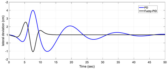
Figure 7.
Comparing the fuzzy-PID and Ziegler–Nichols PD control.
It was observed that, by following the fuzzy rules and with a PID controller with a Kp gain of 0.01, Ki gain of 0, and Kd gain of 0.06, fuzzy-PID was able to steer the vehicle to the desired reference trajectory with fewer oscillations and a settling time of 12 s. Therefore, it can be concluded that fuzzy-PID performed better with fewer oscillations as compared with Ziegler–Nichols PD controllers, with a shorter settling time. Regardless of the different vehicle load and cornering stiffness, it was also observed that fuzzy-PID could easily steer the vehicle towards the reference trajectory, as a result of the fuzzy rule and reasoning. Little lateral deviations of 2 cm were recorded as compared to the Ziegler–Nichols PD control of 4 cm. Moreover, it can be observed that fuzzy-PID was able to stabilize the vehicle when it got to the desired reference trajectory. However, in the case of the Ziegler PD control, mild oscillations were observed all through the vehicle motion. Other simulations were carried out to compare the performance of fuzzy-PID as compared to both Ziegler PD control and MPC control. The result can be seen in Figure 8.
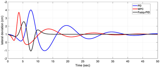
Figure 8.
Comparison of PD, MPC, and fuzzy-PID.
At a steady longitudinal velocity, cornering stiffness, and vehicle mass, the results in Figure 8 shows the performance of PD, MPC, and fuzzy-PID controllers. The simulation results describe/produce/illustrate greater performance on control gains by comparing the fuzzy-PID controller to the PD controller. Moreover, a better performance was achieved based on the fuzzy rule and reasoning setup of a human driving scenario as inputted into the fuzzy rule database. It was also indicative that PID gain scheduling represented human expertise on fuzzy rules. In addition, it was discovered that, although fuzzy-PID does not have an apparent structure of the PID control, the fuzzy logic controller may consider the non-linear PID controller whose parameters can be determined based on error distance.
The main factor that caused the differences in performance observed between the three control methods (fuzzy-PID, Ziegler–Nichols PD, and MPC) in Figure 8 is the utilization of fuzzy logic in the fuzzy-PID controller. The fuzzy-PID controller, through the implementation of fuzzy rules and reasoning, was able to effectively steer the vehicle towards the desired reference trajectory with minimal oscillations and a shorter settling time in comparison to the Ziegler–Nichols PD controller. Furthermore, the Fuzzy-PID controller demonstrated a superior performance in terms of lateral deviation and stabilization under varying vehicle load and cornering stiffness conditions. The simulation results presented in Figure 8 illustrate the improved control gains achieved by the fuzzy-PID controller in comparison to the PD and MPC controllers. This can be attributed to the ability of the fuzzy-PID controller to mimic human driving scenarios through the implementation of fuzzy rules and reasoning, as well as the gain scheduling of the PID controller within the fuzzy-PID controller.
6. Conclusions
The task of steering and keeping a vehicle in its lane is not an easy task. It involves the lateral control of the vehicle by a control algorithm. The objective of this algorithm is to keep the vehicle moving along the desired reference trajectory. The position and orientation of the vehicle can be determined by the use of sensors, such as the camera used in identifying the white middle marker and left and right boundaries on the road. Regardless of the apparent simplicity of discovering white lane marks on the road, it can be extremely hard to find white lane marks on a different kind of road. It is based on these prevailing issues that this study was researched. This study aimed to simulate and analyze a fuzzy-PID lane-keeping control using computer vision image processing with the following objectives: developing a lane detection algorithm used for the simulation of the fuzzy-PID lane-keeping control. The result of this simulation was also compared to other simulated lane-keeping controllers, such as PD and MPC, to compare which performs better. All simulations were conducted using the same parameters
In conclusion, fuzzy-PID controller performance was way better than Ziegler–Nichols PD and MPC in terms of response time and settling time. Fewer overshoots were observed, as fuzzy-PID tried to direct the vehicle along the trajectory of reference. No oscillations were observed, but in the case of PD and MPC control, there exist oscillations as it could be seen in the results that wobbling was observed all through the motion of the vehicle. Moreover, it could be concluded that, regardless of the vehicle parameters in terms of speed, weight, or cornering stiffness, fuzzy-PID had a better performance with a minimal lateral deviation of 2 cm and settling time of 12 s.
Further studies can be recommended on the result of the lane detection algorithm to develop a detection algorithm that uses multiple types of edge detection techniques. The algorithm could be trained to employ any of the detection techniques suitable at any given moment based on the current road condition and weather condition and feed the output processed image to the controller for the suitable steering command.
Author Contributions
Formal analysis, M.S. and K.Y.; Funding acquisition, M.M. and H.A.; Investigation, K.Y.; Methodology, M.S., K.Y. and T.A.B.; Project administration, M.S. and K.Y.; Resources, K.Y.; Software, M.S., K.Y. and T.A.B.; Validation, K.Y., A.A. and T.A.B.; Writing—original draft, M.S., K.Y. and T.A.B.; Writing—review & editing, H.A., A.A. and M.M. All authors have read and agreed to the published version of the manuscript.
Funding
This study received no external funding.
Data Availability Statement
The data presented in this study are available upon request from the corresponding authors.
Conflicts of Interest
The authors declare no conflict of interest.
References
- Rossi, A.; Ahmed, N.; Salehin, S.; Choudhury, T.H.; Sarowar, G. Real-time Lane detection and Motion Planning in Raspberry Pi and Arduino for an Autonomous Vehicle Prototype. arXiv 2009. [Google Scholar] [CrossRef]
- Hoang, T.M.; Baek, N.R.; Cho, S.W.; Kim, K.W.; Park, K.R. Road Lane Detection Robust to Shadows Based on a Fuzzy System Using a Visible Light Camera Sensor. Sensors 2017, 17, 2475. [Google Scholar] [CrossRef] [PubMed]
- Lefèvre, S.; Gao, Y.; Vasquez, D.; Tseng, H.E.; Bajcsy, R.; Borrelli, F. Lane Keeping Assistance with Learning-Based Driver Model and Model Predictive Control. dictive Control. In Proceedings of the 12th International Symposium on Advanced Vehicle Control, Tokyo, Japan, 22–26 September 2014; pp. 1–8. [Google Scholar]
- Romano, R.; Maggi, D.; Hirose, T.; Broadhead, Z.; Carsten, O. Impact of lane keeping assist system camera misalignment on driver behavior. J. Intell. Transp. Syst. 2020, 25, 157–169. [Google Scholar] [CrossRef]
- Li, D.; Lin, S.; Liu, G. Lane departure prediction based on closed-loop vehicle dynamics. Proc. Inst. Mech. Eng. Part I J. Syst. Control. Eng. 2022, 236, 913–926. [Google Scholar] [CrossRef]
- Ershadi, N.Y.; Menéndez, J.M.; Jimenez, D. Robust vehicle detection in different weather conditions: Using MIPM. PLoS ONE 2018, 13, e0191355. [Google Scholar] [CrossRef]
- Waykole, S.; Shiwakoti, N.; Stasinopoulos, P. Review on Lane Detection and Tracking Algorithms of Advanced Driver Assistance System. Sustainability 2021, 13, 11417. [Google Scholar] [CrossRef]
- Lei, Y.; Hu, J.; Fu, Y.; Sun, S.; Li, X.; Chen, W.; Hou, L.; Zhang, Y. Control strategy of automated manual transmission based on active synchronisation of driving motor in electric bus. Adv. Mech. Eng. 2019, 11, 1687814019846734. [Google Scholar] [CrossRef]
- Ploeg, J.; de Haan, R. Cooperative Automated Driving: From Platooning to Maneuvering. In Proceedings of the 5th International Conference on Vehicle Technology and Intelligent Transport Systems (VEHITS 2019), Heraklion, Crete, Greece, 3–5 May 2019; pp. 5–10. [Google Scholar]
- Somasundaram, G.; Kavitha; Ramachandran, K.I. Lane Change Detection and Tracking for a Safe-Lane Approach in Real Time Vision Based Navigation Systems. In Computer Science, Mathematics, Engineering; Institute for Computer Science and Technology: Washington, DC, USA, 2011; pp. 345–361. [Google Scholar] [CrossRef]
- Kuo, C.; Lu, Y.; Yang, S. On the Image Sensor Processing for Lane Detection and Control in Vehicle Lane Keeping Systems. Sensors 2019, 19, 1665. [Google Scholar] [CrossRef] [PubMed]
- Kaur, G.; Kumar, D. Lane Detection Techniques: A Review. Int. J. Comput. Appl. 2015, 112, 975–8887. [Google Scholar]
- Zhao, R.; Qin, D.; Chen, B.; Wang, T.; Wu, H. Thermal Management of Fuel Cells Based on Diploid Genetic Algorithm and Fuzzy PID. Appl. Sci. 2022, 13, 520. [Google Scholar] [CrossRef]
- Wu, G.; Luo, W.; Guo, J.; Zhang, J. A Sigmoid-plane adaptive control algorithm for unmanned surface vessel considering marine environment interference. Trans. Inst. Meas. Control. 2022, 44, 2076–2090. [Google Scholar] [CrossRef]
- Hagler, J.C.; Lamb, D.J.; Tian, Q. Towards Greener Solutions for Steering Angle Prediction. arXiv 2022, arXiv:2211.11133. [Google Scholar]
- Matute, J.A.; Marcano, M.; Diaz, S.; Perez, J. Experimental Validation of a Kinematic Bicycle Model Predictive Control with Lateral Acceleration Consideration. IFAC Pap. OnLine 2019, 52, 289–294. [Google Scholar] [CrossRef]
- Kanchwala, H.; Viana, I.B.; Aouf, N. Cooperative path-planning and tracking controller evaluation using vehicle models of varying complexities. Proc. Inst. Mech. Eng. Part C J. Mech. Eng. Sci. 2020, 235, 2877–2896. [Google Scholar] [CrossRef]
- Pereira, G.C. Lateral Model Predictive Control for Autonomous Heavy-Duty Vehicles: Sensor, Actuator, and Reference Uncertainties. Doctoral Dissertation, KTH Royal Institute of Technology, Stockholm, Sweden, 2020. [Google Scholar]
- Alfred, C.F.R.; Wicks, L.; Chair; John; Ferris, B.; Dennis; Hong, W.; Samuel; Kherat, M. A Method for Modeling and Prediction of Ground Vehicle Dynamics and Stability in Autonomous Systems. Ph.D. Dissertation, Virginia Tech, Blacksburg, VA, USA, 2011. [Google Scholar]
- Betz, J.; Wischnewski, A.; Heilmeier, A.; Nobis, F.; Stahl, T.; Hermansdorfer, L.; Lohmann, B.; Lienkamp, M. What can we learn from autonomous level-5 motorsport? In 9th International Munich Chassis Symposium 2018: Chassis. Tech Plus; Springer: Wiesbaden, Germany, 2018; pp. 123–146. [Google Scholar] [CrossRef]
- Bachiller-Burgos, P.; Manso, L.J.; Bustos, P. A variant of the Hough Transform for the combined detection of corners, segments, and polylines. EURASIP J. Image Video Process. 2017, 2017, 2027. [Google Scholar] [CrossRef]
- Rokonuzzaman, M.; Mohajer, N.; Nahavandi, S.; Mohamed, S. Review and performance evaluation of path tracking controllers of autonomous vehicles. IET Intell. Transp. Syst. 2021, 15, 646–670. [Google Scholar] [CrossRef]
- Cheein, F.A.A.; Cruz, C.; Bastos, T.F.; Carelli, R. SLAM-based Cross-a-Door Solution Approach for a Robotic Wheelchair. Int. J. Adv. Robot. Syst. 2010, 7, 155–164. [Google Scholar] [CrossRef]
- Lenain, R.; Thuilot, B.; Cariou, C.; Martinet, P. Model Predictive Control for vehicle guidance in presence of sliding: Application to farm vehicles’ path tracking. In Proceedings of the 2005 IEEE International Conference on Robotics and Automation, Barcelona, Spain, 18–22 April 2005; pp. 885–890. [Google Scholar]
- Wang, W.; Kenzo, N.; Yuta, O. Model Reference Sliding Mode Control of Small Helicopter, X.R.B based on Vision. Int. J. Adv. Robot. Syst. 2016, 5, 233–242. [Google Scholar] [CrossRef]
- Zhao, Z.-Y.; Tomizuka, M.; Isaka, S. Fuzzy gain scheduling of PID controllers. IEEE Trans. Syst. Man Cybern. 1993, 23, 1392–1398. [Google Scholar] [CrossRef]
- Han, S.-Y.; Dong, J.-F.; Zhou, J.; Chen, Y.-H. Adaptive Fuzzy PID Control Strategy for Vehicle Active Suspension Based on Road Evaluation. Electronics 2022, 11, 921. [Google Scholar] [CrossRef]
Disclaimer/Publisher’s Note: The statements, opinions and data contained in all publications are solely those of the individual author(s) and contributor(s) and not of MDPI and/or the editor(s). MDPI and/or the editor(s) disclaim responsibility for any injury to people or property resulting from any ideas, methods, instructions or products referred to in the content. |
© 2023 by the authors. Licensee MDPI, Basel, Switzerland. This article is an open access article distributed under the terms and conditions of the Creative Commons Attribution (CC BY) license (https://creativecommons.org/licenses/by/4.0/).