Article

Fast FPGA-Based Multipliers by Constant for Digital Signal Processing Systems

Department of Computer Science and Engineering, Saint Petersburg Electrotechnical University “LETI”, Saint Petersburg 197022, Russia
*
Author to whom correspondence should be addressed.
Electronics 2023, 12(3), 605; https://doi.org/10.3390/electronics12030605
Submission received: 28 December 2022 / Revised: 23 January 2023 / Accepted: 24 January 2023 / Published: 26 January 2023
(This article belongs to the Special Issue Efficient Algorithms and Architectures for DSP Applications)

Abstract

:
Traditionally, the usual multipliers are used to multiply signals by a constant, but multiplication by a constant can be considered as a special operation requiring the development of specialized multipliers. Different methods are being developed to accelerate multiplications. A large list of methods implement multiplication on a group of bits. The most known one is Booth’s algorithm, which implements two-digit multiplication. We propose a modification of the algorithm for the multiplication by three digits at the same time. This solution reduces the number of partial products and accelerates the operation of the multiplier. The paper presents the results of a comparative analysis of the characteristics of Booth’s algorithm and the proposed algorithm. Additionally, a comparison with built-in FPGA multipliers is illustrated.

1. Introduction

Traditionally, multimedia applications require high data processing speed due to the need to process the large amounts of data in real time. The performance of digital filters, windowing and Fourier transform blocks, and other arithmetic processors is mainly determined by the speed of the multipliers; so, the development of high-speed multipliers is relevant [1,2,3]. The situation is similar when implementing the convolutional neural networks; the number of multipliers on each layer can be very large [4,5,6,7]. The hardware implementation of signal processing systems for many applications is based on the Field-Programmable Gate Array (FPGA). FPGA architecture allows for the continuous processing of input data due to the maximum parallelization of the calculations. FPGAs have embedded hardware multipliers, but multiplication can also be implemented using the logic cells. In some cases, the use of the logical cells is preferable. This is because the number of multipliers in an FPGA is limited, and their location and digit capacity are fixed. Moreover, the logic cells of modern FPGAs have an improved architecture which increases the performance of the arithmetic circuits [8].
To increase the multiplication speed, various algorithmic methods have been developed. The first group of methods is based on decreasing the number of partial products by processing several digits of a multiplier simultaneously. These methods are based on Booth’s algorithm [9], which performs multiplication by two digits at once, halving the number of partial products. A modified Booth’s algorithm [10] is also used. It reduces the number of partial products by less than half but does not require any preliminary operations to compute the partial products. Subsequent modifications of Booth’s multipliers dealt with improving accuracy [11,12], minimizing the complexity of the design [13], and accelerating the operation [13,14,15]. There are also known extensions of Booth’s algorithm to perform more complex operations, such as the multiplication of three arguments [16,17]. The second group of multiplication optimization methods is related to paralleling the summation of partial products because the classical methods of summation (iterative and linear) are slow. One of the most effective methods of acceleration is based on the Wallace tree [18], which implements the addition of different bits of partial products at the same time. Wallace tree implementations are also constantly being modified to minimize hardware costs [19] and delays [20,21,22]. Pipelining is used to improve the performance of multipliers [23]. Often, all of these methods are used simultaneously [24,25,26].
The improvement of the time characteristics of multipliers can be achieved by using tabular methods [27,28]. The choice of a specific optimization method depends on the hardware implementation technology. For FPGA-based digital design, tabular methods are most often used [29,30,31], as well as the methods focused on paralleling computational operations [32,33,34]. This makes it possible to obtain simple, fast computational blocks.
Constant coefficient multipliers are a special class of multipliers; these units perform multiplication by a fixed constant. These multipliers are often found in many signal processing applications where one of the multiplication arguments is constant. They can be filter coefficients, window function values, Fourier transform coefficients, and weights of a neural network. Traditionally the usual multipliers are used for signal multiplication by a constant, i.e., the multiplication is performed according to the same algorithm as the multiplication of one signal by another with an unknown value. At the same time, the constant coefficient multipliers can be optimized to be simpler and faster than the general purpose multipliers.
The configurable logic blocks of FPGAs designed to implement logic functions consist of a look-up table (LUT) with 4–6 inputs, depending on the FPGA family, the flip-flops, and the multiplexers. Due to this structural feature, when implementing arithmetic on an FPGA it is possible to use table methods based on the different table algorithms. These are, for example, the constant factor multiplier method based on canonical recoding, using the special algorithms to find the optimal chains of adders, subtractors, and shift elements [35]; the constant factor multiplier construction method, using fine-grained FPGA memory resources and the special table search method [36]; and the method using the pre-computation of partial products [37].
In our paper, we have integrated different approaches to building the fast multipliers and evaluated the possibilities and effectiveness of their implementations in FPGA technologies. This paper is structured as follows. In 
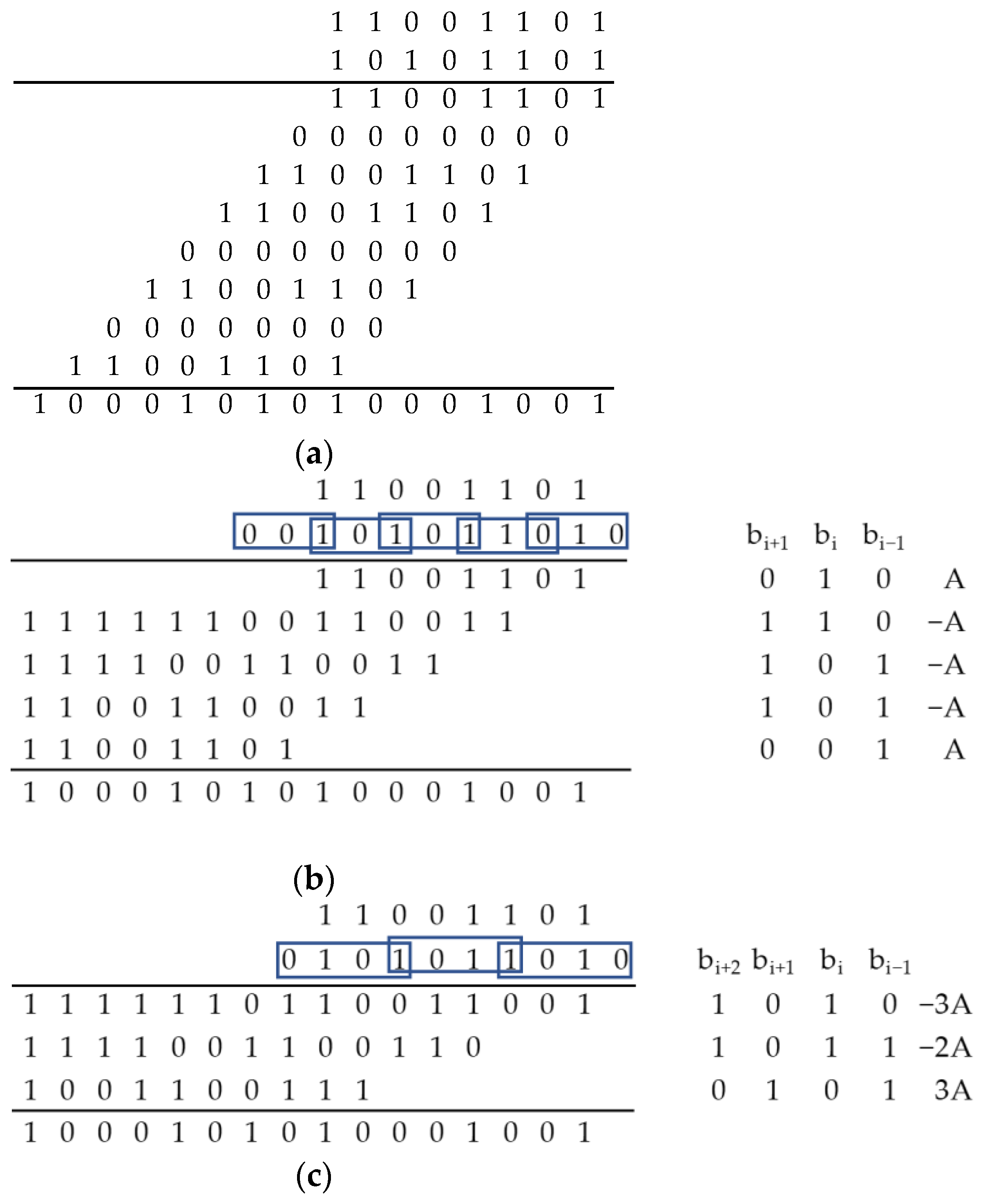
Section 2, we consider the multiplication acceleration method based on Booth’s algorithm (multiplication by two digits at a time) with maximal parallelization of partial product addition. We also propose the modification of this algorithm by the multiplication by three digits at a time. Section 3 describes the implementation of the considered methods of multiplying two input binary codes as well as the input binary code by a constant on the FPGA. The results of the development are discussed in Section 4, and the conclusion is given in Section 5.

2. Materials and Methods

Analysis of the traditional matrix multiplier shows that the largest delay in the calculation is caused by the summation of partial products (PPs). Reducing their number reduces the summation time. Booth’s method of implementing multiplication by groups of bits is widely spread in practice. The hardware implementation of this method is known both on the basis of the FPGA and on the application-specific integrated circuit (ASIC) [13,15,23].

2.1. Mathematical Basis of Booth’s Algorithm

Booth’s algorithm can be constructed based on the following reasoning. Suppose it is necessary to calculate the following product:
P = A B = A ( b n 1 2 n 1 + b n 2 2 n 2 + + b 0 2 0 ) .
The implementation of this expression is related to the generation of PPs of the form A     b i 2 i for i = 0, 1, …, n−1. The number of such products is equal to the digit of the multiplier n. Let us convert b i 2 i as follows:
b i 2 i = b i 2 i ( 2 1 ) = b i 2 i + 1 2 2 b i 2 i = b i 2 i + 1 2 b i 2 i 1 .
This expression shows how one can reduce the number of PPs by decomposing the partial product i into the partial products i + 1 and i − 1. Figure 1 illustrates the decomposition of the even PPs into odd ones.
The considered approach allows the exclusion of the even (or odd) powers. This will change the values of the PPs and reduce their number by about half since each even (odd) bit will be “distributed over the neighboring” bits. This decrease in the PP number will reduce the time required to perform the summation. To correctly process bit 0 (with power 2 0 ), the bit grid should be extended by introducing the summand b 1 2 1 . The remaining partial products have the following form:
R i = A ( 2 b i + 1 + b i + b i 1 ) 2 i ,
and the result of the multiplication is described by the following equation:
P = A ( 2 b 1 + b 0 + b 1 ) 2 0 + A ( 2 b 3 + b 2 + b 1 ) 2 2 + A ( 2 b 5 + b 4 + b 3 ) 2 4 = A i = 0 n 2 1 ( 2 b 2 i + 1 + b 2 i + b 2 i 1 ) 2 2 i
As the number of the PPs has decreased by about a factor of two, we can talk about multiplication by two digits simultaneously. Based on the expression in the parentheses in (1), we can write the table (Table 1) for the partial products for all the combinations ( b i + 1 , b i , b i 1 ) .
The considered algorithm can be implemented in the hardware. On the basis of the multiplicand A, all the possible variants of the partial products that require transformations (−A, 2A, −2A) should be generated beforehand. Furthermore, depending on the triplets of the analyzed digits of multiplier B ( b i + 1 , b i , b i 1 ), the needed variant of the partial product is chosen and summed up, taking into account the shift corresponding to the position of the analyzed triplet.

2.2. Multiplication Algorithm for Three Digits at a Time

We propose to develop the considered Booth’s algorithm by implementing multiplication for three digits at a time.

2.2.1. Mathematical Basis for the Implementation of Three Digit Multiplication

Suppose it is necessary to calculate the following product:
P = A B = A ( b n 1 2 n 1 + b n 2 2 n 2 + b 1 2 1 + b 0 2 0 ) .
To determine the method of reducing the number of PPs, let us perform the following transformations:
P = A ( b n 1 2 n 1 + b n 2 2 n 2 + + ( 2 b 8 2 8 b 8 2 8 ) + b 7 2 7 + b 6 2 6 + ( 2 b 5 2 5 b 5 2 5 ) + b 4 2 4 + b 3 2 3 + ( 2 b 2 2 2      b 2 2 2 ) + b 1 2 1 + b 0 2 0 + b 1 2 1 )
To correctly process bit 0 (with power 2 0 ), the bit grid has to be expanded by introducing the summand b 1 2 1 . The introduction of this summand does not violate the expression because the zero bit is used for expansion, i.e., b 1 = 0 . The brackets in expression (2) do not change the order of operations but illustrate the representation of each bit with numbers from the row {2, 5, 8, 11, …, 3i–1} for 0 ≤ i ≤ n/3–1. Next, let us perform the regrouping of the summands. The regrouping is also shown in the parentheses in the following expression:
P = A ( 4 b n 1 2 n 1 + 2 b n 2 2 n 2 + + ( 4 b 8 2 6 + 2 b 7 2 6 + b 6 2 6 + b 5 2 6 ) + ( 4 b 5 2 3 + 2 b 4 2 3 + b 3 2 3 + b 2 2 3 )      + ( 4 b 2 2 0 + 2 b 1 2 0 + b 0 2 0 + b 1 2 1 ) ) = A ( ( 4 b n 1 + 2 b n 2 + b n 3 + b n 4 ) 2 n 3 + + ( 4 b 8 + 2 b 7 + b 6 + b 5 ) 2 6 + ( 4 b 5 + 2 b 4 + b 3 + b 2 ) 2 3      + ( 4 b 2 + b 1 + b 0 + b 1 ) 2 0 ) = A i = 0 3 n ( 4 b 3 i + 2 + 2 b 3 i + 1 + b 3 i + b 3 i 1 ) 2 3 i
According to expression (3), every third bit of the series {0, 3, 6, 9, 12,…} is counted in two adjacent groups. Figure 2 shows this formation of the power sequence in the sum of the partial products.
Equation (3) is valid for the case when n is divisible by 3 without a remainder. Otherwise, it is necessary to supplement the code B with the necessary number of high zero digits.
The proposed approach reduces the number of partial products by a factor of about three, allowing us to talk about multiplication by three digits simultaneously. This will reduce the time required to perform summation, as compared to the modified Booth’s algorithm. The partial products used to calculate the result have the following form:
R i = A ( 4 b 3 i + 2 + 2 b 3 i + 1 + b 3 i + b 3 i 1 ) 2 3 i ,
Based on the expression in the brackets in formula (4) we compiled the table (Table 2) for the partial products for all the combinations ( b i + 2 , b i + 1 , b i , b i 1 ) .
High performance of the hardware implementation of the algorithm is achieved by generating the PPs simultaneously. Based on the multiplicand A, all possible variants of the PPs that require transformations should be generated beforehand: −4A, −3A, −2A, −A, 2A, 3A, and 4A. Subsequently, depending on the four analyzed bits of the multiplier B, the desired variant of the partial product is selected and summarized, taking into account the shift corresponding to the position of the analyzed four bits, b i + 2 , b i + 1 b i , b i 1 . The operation of multiplying the argument A by 3 may present some difficulty. To implement it, it is proposed to shift the argument A to the left by one position (shifting bits to the left corresponds to multiplying by 2) and to add A. This combination of simple operations corresponds to multiplication by 3. The proposed version of the algorithm is focused on the operations with direct binary codes, i.e., with positive numbers. To multiply the signed numbers, it is possible to generate a sign digit separately using an XOR operation for the sign bits of the arguments. If the arguments come in complementary codes, the considered multiplier can be supplemented by converters from the complementary code to the direct binary code at the argument’s inputs and by the direct-to-complementary code converter at the outputs. It is also possible to adapt the proposed algorithm to work with the complementary codes.
Table 3 shows the work of the algorithm for the multiplication of the two arguments A = (11001101)2 = (205)10 and B = (10101101)2 = (173)10.
P = (1101 1001 1001)2 + (1110 0110 0110) 2 × 8 + (0010 0110 0111) 2 × 64 = (35,465)10 = 205 × 173.
Figure 3 shows a comparison of the proposed algorithm with the traditional multiplication algorithm and Booth’s algorithm for multiplication A × B.
Analysis of the example in Figure 3 shows that the number of PPs when multiplying 8-bit arguments for the traditional algorithm is 8; for Booth’s algorithm, it is 4; and for the proposed algorithm, it is 3. With the increasing of the digit capacity of the arguments, the difference will grow. For example, for the considered algorithms the number of PPs is 16, 8, and 6, respectively, for the multiplication of 16-bit arguments. Reducing the number of partial products decreases the number of adders needed.

2.2.2. Hardware Implementation of the Algorithm

Figure 4 shows the architecture of the unit implementing the proposed algorithm for fast multiplication by three digits at a time.
In this scheme, the multiplicand A arrives at a number of transducers, producing all possible variants of the partial products: 2A, 3A, 4A, −4A, −3A, −2A, and −A, except for A itself and zero, because they do not require circuit implementation. The bits of multiplier B go to the address inputs of the multiplexers to select one or the other variant of the partial product. The final result is obtained by summing the PPs, taking into account their mutual arrangement in the bit grid, which is ensured by shifting the partial product to the left by 3i digits, where 0 ≤ i ≤ n/3–1.

3. Designing a Multiplier on the FPGA Basis

To determine the efficiency of the proposed method, we compared its characteristics with the implementation of the modified Booth’s algorithm, performing multiplication by two digits at a time, as presented in Section 2.1. We also analyzed the characteristics of the multipliers with an embedded FPGA multiplier. All the compared variants of the multiplier per constant were described in the Verilog HDL language; the RTLs were generated for Cyclone 10 LP chips using Intel® Quartus® Prime. Altera’s ModelSim was used to simulate the synthesized multipliers. The frequency response analysis of the developed circuits was performed using the TimeQuest Timing Analyzer (Intel® Quartus® Prime utility). For the correct timing analysis, we used the test setup shown in
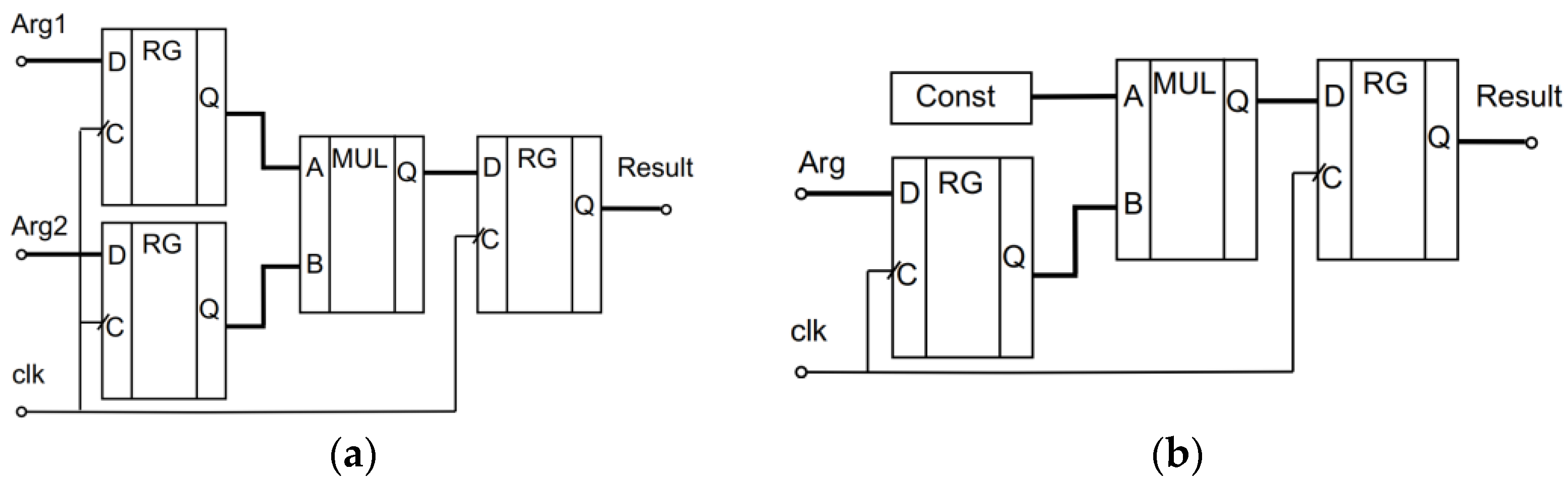
 Figure 5.
The proposed architecture is used to determine the Fmax; this frequency is calculated only for the paths where the source and target registers or ports are controlled by the same clock.

3.1. Hardware Implementation of the Modified Booth’s Algorithm

To perform the research, the modified Booth’s algorithm was implemented in two variants: the multiplication of two arguments and the multiplication of an argument by a constant.

3.1.1. Implementation of Two Binary Code Multiplication

For the investigation, we used a parameterized description of the multiplier, allowing for a rapid change in its digit capacity. 
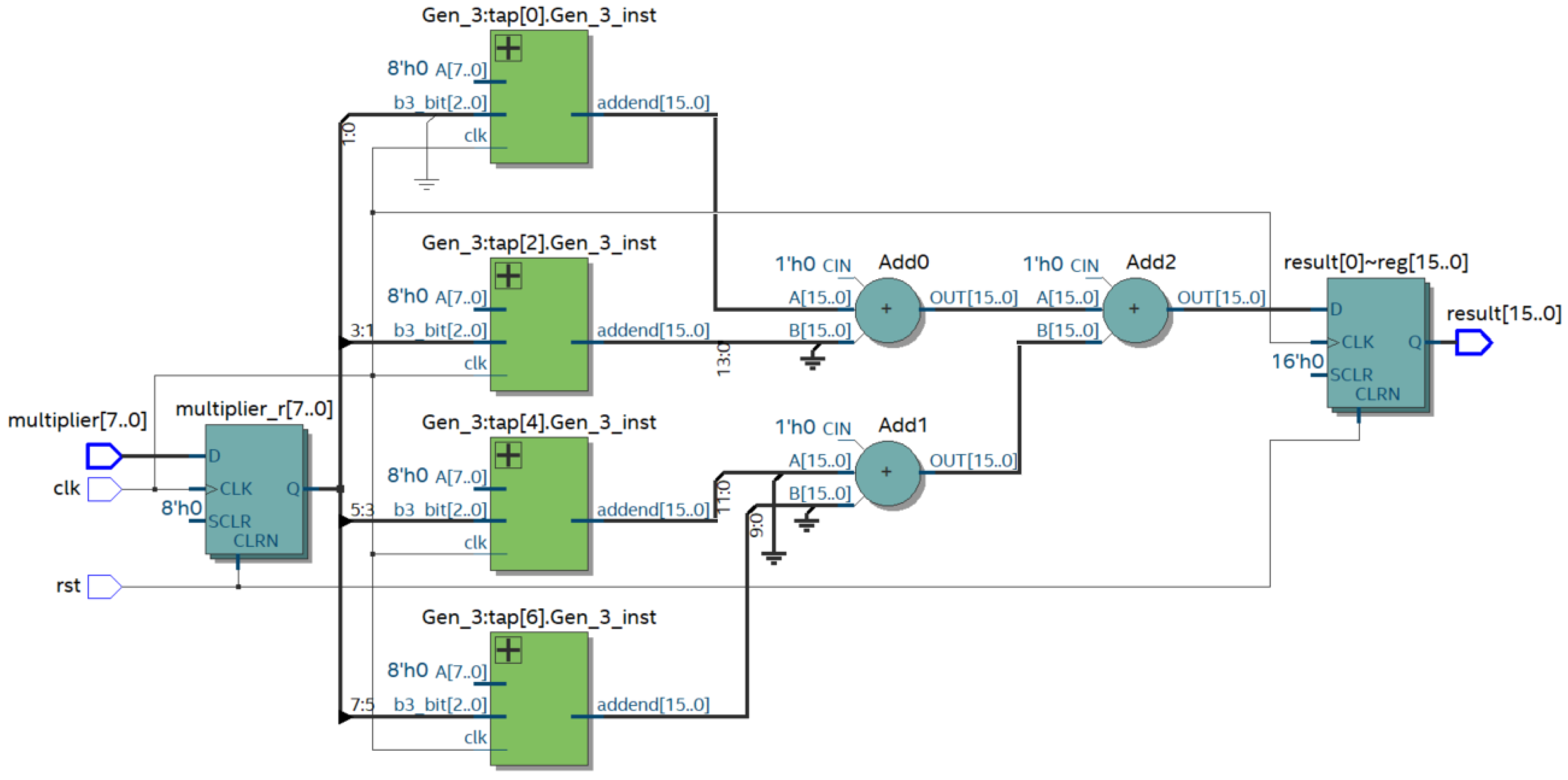
Figure 6 shows the result of compiling the prepared Verilog HDL description with a bit size of n = 8.
The multiplier uses partial product generation modules (modules Gen_3) based on the three bits of the multiplier. These modules generate PPs according to the rules shown in Table 1. The summation of the PPs is performed pairwise; three adders are used for the 8-bit multiplier. In the study, we evaluated the change in the maximum frequency of the module, as well as the required resources of the FPGA Cyclone 10 LP for multiplication as a function of the digit capacity of the codes to be multiplied. The results are presented in Table 4.
The table shows the maximum possible frequencies of the multiplier. These frequencies were calculated using the Slow1 and Slow2 models corresponding to the different operating parameters (voltage and temperature) considered in the static time analysis. The following characteristics are used: Slow1—1200 mV, 100 °C.; Slow 2—1200 mV, −40 °C. The models are based on determining the lowest speed-up for the different paths; the model is built for the chip with the worst speed-up. For both models, there is a decreasing trend in frequency with the minor spikes.

3.1.2. Implementation of the Constant Coefficient Multiplier

Figure 7 shows the RTL of the 8-bit constant coefficient multiplier (CCM). The FPGA distributed memory is used to store the constants. The basis of distributed memory is LUTs; in most FPGA families, they have six inputs and allow for the storage of 64 bits. This type of memory is quite flexible and supports a variety of data widths, unlike block memory, where the bit depth of the stored words and their number can take certain values depending on the type of block memory. The flexibility of distributed memory and its high speed make it ideal for storing partial products.
The partial product generation modules (Gen_3) for the CCM are designed using distributed FPGA memory, which stores the pre-calculated partial products for the constant multiplicand. The modules Gen_3 select the partial product from the memory according to the value of three bits of the multiplier. The maximum frequency Fmax of the multiplier and the required FPGA resources were analyzed during the study of this module. Table 5 shows the dependence of the analyzed parameters on the digit capacity of the arguments.
Analysis of the RTL multiplier presented in Figure 7 shows that it can be easily pipelined. Figure 8 illustrates a pipeline implementation of the Booth’s multiplier. The productivity of the pipeline circuit depends on the number of stages and the ratio of the combinational and the register parts performance. It tends to the value t/m, where t is the working time of the original circuit, and m is the number of pipeline steps.
The increment of the hardware costs to implement the pipeline method of processing depends on the number of registers entered. The maximum effect is given by the pipelining of the summing. Although pipelining leads to additional hardware, it speeds up the multiplication operation by 2–3 times. Table 6 shows the characteristics of the pipelined constant coefficient of the Booth’s multiplier.

3.2. Hardware Implementation of the Proposed Algorithm for Multiplying by Three Bits at a Time

The proposed multiplication algorithm for multiplying by three bits at a time has also been implemented and investigated in two variants: the multiplication of two arguments and the multiplication of an argument by a constant.

3.2.1. Implementation of Two Binary Code Multiplication

The parameterized description was used to investigate the three-bits-at-a-time multiplier (TBTM). The parametrization makes it possible to easily change the digit capacity of the arguments and to analyze the evolution of the maximum frequency Fmax of the unit and to estimate the hardware cost of the multiplier implementation. 
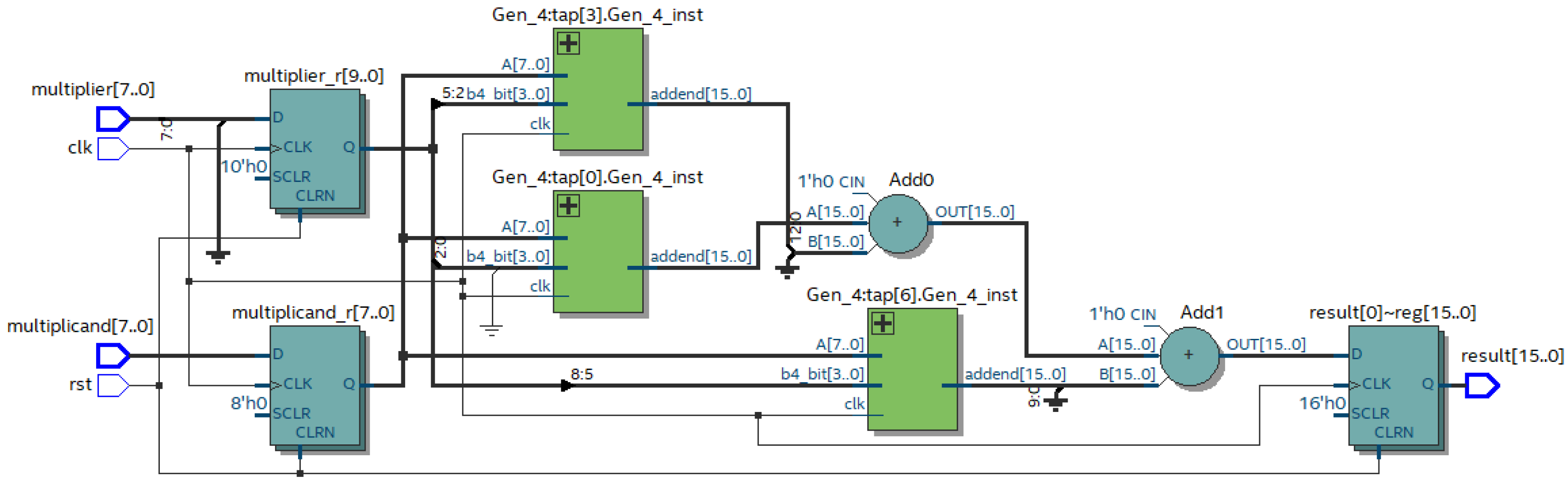
Figure 9 shows the result of the compiling of the prepared Verilog HDL description for the eight-bit implementation.
The multiplier uses partial product generation modules (Gen_4) based on the four analyzed bits of the multiplier. These modules generate PPs for the multiplicand according to the rules presented in the Table 2. The summation of the three PPs is performed using two adders.
A comparison of Figure 6 and Figure 9 shows the reduction in the blocks for the formation of the PPs with some of their complications, as well as the reduction in the number of adders. The multiplication of the eight-digit arguments requires three PPs and consequently needs two adders for their addition. The implementation of Booth’s algorithm forms four PPs and requires three adders. The characteristics of the multiplier realizing the proposed algorithm for the different argument digit capacities are presented in Table 7.

3.2.2. Implementation of the Constant Coefficient Multiplier

Figure 10 shows the RTL of the hardware implementation of the proposed algorithm that performs multiplication by a constant.
The Gen_4 modules of the CCM implement a selection of the partial product stored in the FPGA’s distributed memory. The address for the selection is generated based on the four bits of the multiplier. Table 8 shows the characteristics of the CCM that implement the proposed algorithm for the different digit capacities of the arguments.

4. Discussion

This paper presents an analysis of several variants of the implementation of the input code multipliers by a constant. One is based on Booth’s algorithm, the other implements multiplication by three digits at once. The comparison was made for the variant of multiplication of two codes and a code by a constant because the implementations of these methods on the FPGA basis were different. To ensure a correct comparison, we disabled the optimization when compiling in Quartus Prime. This guaranteed that all of the elements provided in the Verilog HDL description were preserved.
Table 9 integrates the characteristics of the two code multipliers and the constant code multipliers realized by Booth’s algorithm and by the proposed algorithm for the multiplication of three digits at once. The table shows the maximum frequency Fmax for the Slow1 model and the total number of logic elements (LE) used. The results of the Slow2 timing analysis model and the number of combinational functions have the same trends. The number of registers is constant for all the multipliers because, according to Figure 5, the registers are used to fix the arguments and results, and their number does not depend on the realized algorithm.
The analysis of the table shows that the maximum possible frequency Fmax when realizing the multiplication of two arguments in the Booth’s multiplier (in the column Booth’s MUL Fmax) is higher than in the three-bit multiplier (in the column TBTM Fmax). This is due to the fact that for the generation of the PPs in the Booth’s multiplier the elementary operations—shift, inversion, and increment—are sufficient. The proposed algorithm requires more time-consuming calculations, such as when calculating the partial products of 3A and −3A. The situation changes when the input code is multiplied by a constant. As the PPs are pre-calculated, no complex operations are required and the maximum possible frequency Fmax in the Booth’s multiplier (in the Booth’s CCM Fmax column) is lower than the Fmax of the three-bit multiplier (in the TBT CCM Fmax column). In the hardware cost analysis, the situation is the opposite. The generation of the partial products during computation requires a lot of FPGA resources. If the precalculated partial products are stored in the distributed memory, the hardware costs are reduced.
Figure 11 shows the growth of the maximum frequency with the increasing digit capacity. The comparison was made for two timing models (Slow1 and Slow2); as can be seen in the figure, the frequency trends are the same.
Figure 12 shows the dependence of the hardware costs on the multiplier’s digit capacity.
The analysis shows that the hardware costs increase significantly when the multiplication of two arguments is implemented; at the same time, there is a minimal increase when multiplying by a constant. In other words, it is obvious that if multiplication by a constant is required, it is necessary to use an appropriate multiplier and not to replace it with a universal one that multiplies the arguments.
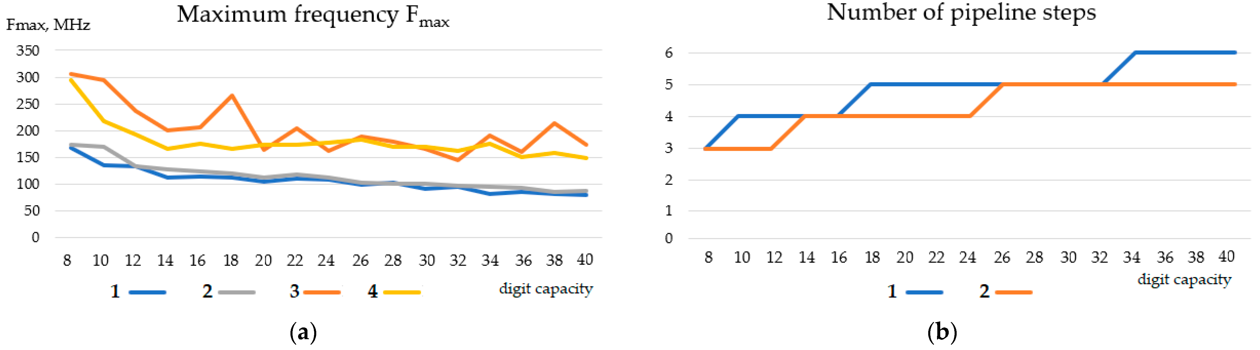
Piping allows the raising of the frequency of the multiplier. Figure 13 illustrates the frequency change when the multiplier is pipelined. The maximum frequency after pipelining in the implementation of Booth’s algorithm for some bits exceeds the frequencies of the device by the proposed algorithm. However, in the proposed algorithm the reducing of the number of partial products and the corresponding reduction in the adder numbers leads to a decreasing of the pipeline stages number, as shown in Figure 13b. In most cases, reducing the number of pipeline steps in the TBT multiplier decreases the time required to obtain a multiplication result.
We also compared the considered solutions with the characteristics of the devices designed using embedded FPGA multipliers with different argument digit capacities. 
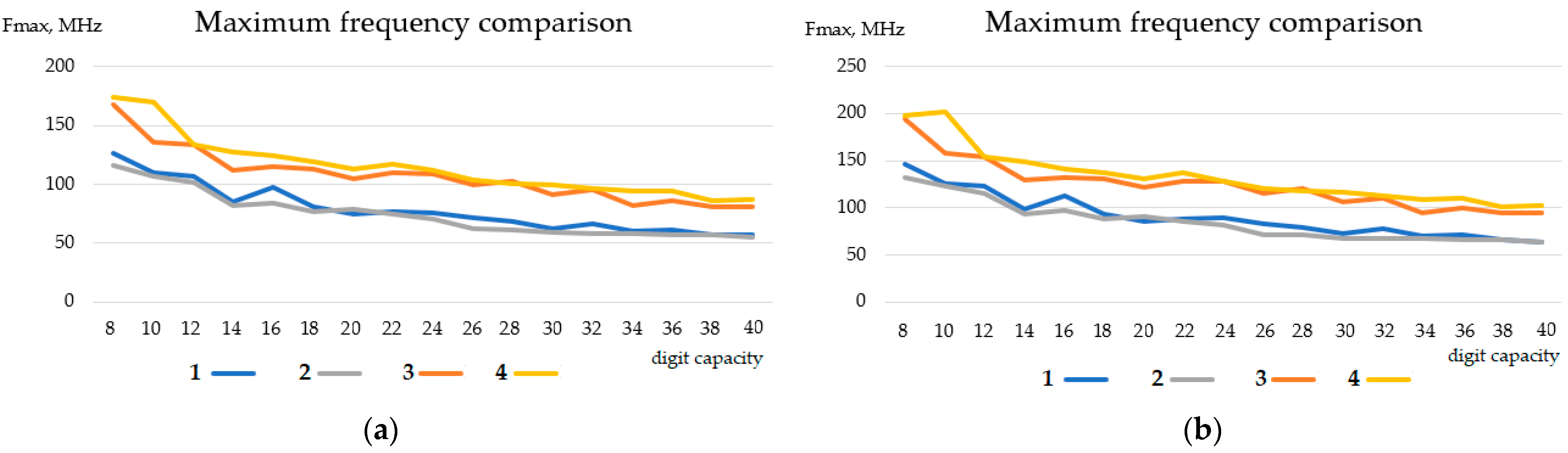
Figure 14 shows a comparison of the TBTM-based and the FPGA embedded multiplier-based constant coefficient multipliers.
The embedded FPGA multipliers are configured as 9 × 9 or 18 × 18 units. This explains the nature of the graphs in Figure 14a. Embedded multipliers are fast, and when multiplying arguments with a digit capacity not greater than 18, they operate at maximum frequency. This frequency exceeds the frequency of the proposed three-bits-at-a-time multiplier by about twice. When the multiplier capacity exceeds 18 digits, the frequency decreases sharply and becomes the same as the frequency of the TBTM. This is due to the need of the cascading multiplier and the corresponding complication of the FPGA internal resources routing. In this case, the number of multipliers required increases dramatically. As Figure 14b shows, seven embedded multipliers are required to multiply two codes with a bit capacity of more than 18 bits. This is why there are sharp drops in the maximum frequency (Figure 14a) at the points corresponding to the digit capacities n = 10 and n = 20. That is, when cascading fast embedded multipliers, the time characteristics of the multiplier device fall sharply. Setting up embedded multipliers for multiplication by a constant does not change the timing characteristics of the resulting unit.
Multiplication operands based on logical cell tables have no limitations in capacity. The number and location of the built-in multipliers are fixed, while LUT-based multipliers can be placed anywhere, and their number is limited only by the size of the reconfigurable matrix.
The effectiveness of the proposed approach of multiplication by a constant using a combination of three-digit multiplication methods with the tabular generation of partial products can be illustrated by the FIR filter design. We compared three implementations of a 32nd order lowpass FIR filter with 20-bit coefficients and 20-bit input codes. In the first version, the filter coefficients were stored in the distributed memory, and the hardware implementation of the multiplication was not specified. In the Verilog HDL program, the multiplication operator was used. In the second version, the multiplication by coefficients was performed using Booth’s CCM. The third version used the developed three-bits-at-a-time multipliers to multiply by the coefficients. Table 10 shows the hardware cost of the filter implementation, and Table 11 presents the frequency characteristics of the three FIR filter variants considered.
Analysis of the data in the tables shows that the filter built using the proposed three-bits-at-a-time multipliers has the best frequency and hardware cost characteristics.

5. Conclusions

In the paper, we proposed an approach to the implementation of multiplication that performs multiplication by three digits. The rate of the multipliers implementing multiplication on a group of bits depends on the number of grouped bits and the depth of the tree realizing the parallel summation of the partial products. Our approach reduces the number of partial products and the depth of the tree, thus increasing the performance of the module. The proposed solution reduces the performance difference between the embedded FPGA multipliers and the multipliers implemented on logical cells. A comparison of the developed multipliers with Altera’s multiplying library of parameterized modules showed the advantage of the proposed multiplication by three digits at a time.
The paper can be used by designers of digital circuits to select an optimal method of multiplier implementation on FPGAs with regard to their design constraints.
Further development of the method of multiplication by a group of digits can be associated with the creation of algorithms and hardware modules multiplying by four, five, and more digits at a time.

Author Contributions

Conceptualization, O.B. and S.M.; methodology, S.M.; software, O.B.; validation, S.M.; formal analysis, S.M.; investigation, O.B.; writing—original draft preparation, O.B.; writing—review and editing, S.M.; visualization, O.B. and S.M.; supervision, S.M. All authors have read and agreed to the published version of the manuscript.

Funding

This work was supported by the Ministry of Science and Higher Education of the Russian Federation by the Agreement № 075-15-2020-933 dated 13.11.2020 on the provision of a grant in the form of subsidies from the federal budget for the implementation of state support for the establishment and development of the world-class scientific center, the «Pavlov center «Integrative physiology for medicine, high-tech healthcare, and stress-resilience technologies».

Conflicts of Interest

The authors declare no conflict of interest.

Abbreviations

The following abbreviations are used in this manuscript:
FPGAField-Programmable Gate Array
LUTLook-up Table
ASICApplication-Specific Integrated Circuit
PPsPartial Products
RTLRegister-Transfer Level
CCMConstant coefficient multiplier
TBTMThree-Bits-at-a-Time Multiplier

References

  1. Mallya, S.N.; Revankar, S. Efficient Implementation of Multiplier for Digital FIR Filters. Int. J. Eng. Res. 2015, V4, 1661–1664. [Google Scholar] [CrossRef]
  2. Shukla, T.; Shukla, P.K.; Prabhakar, H. High speed multiplier for FIR filter design using window. In Proceedings of the International Conference on Signal Processing and Integrated Networks (SPIN), Noida, India, 20–21 February 2014; pp. 486–491. [Google Scholar] [CrossRef]
  3. Umadevi, S.; Vigneswaran, T. Reliability improved, high performance FIR filter design using new computation sharing multiplier: Suitable for signal processing applications. Clust. Comput. 2018, 22, 13669–13681. [Google Scholar] [CrossRef]
  4. Cariow, A.; Cariowa, G.; Paplinski, J.P. An Algorithm for Fast Multiplication of Kaluza Numbers. Appl. Sci. 2021, 11, 8203. [Google Scholar] [CrossRef]
  5. Kim, M.S.; Del Barrio, A.A.; Kim, H.; Bagherzadeh, N. The Effects of Approximate Multiplication on Convolutional Neural Networks. IEEE Trans. Emerg. Top. Comput. 2021, 10, 904–916. [Google Scholar] [CrossRef]
  6. Mironov, S.E.; Bureneva, O.I.; Milakin, A.D. Analysis of Multiplier Architectures for Neural Networks Hardware Implementation. In Proceedings of the III International Conference on Neural Networks and Neurotechnologies (NeuroNT), Saint Petersburg, Russia, 16 June 2022; pp. 32–35. [Google Scholar] [CrossRef]
  7. Aizaz, Z.; Khare, K. State-of-Art Analysis of Multiplier designs for Image processing and Convolutional Neural Network Applications. In Proceedings of the International Conference for Advancement in Technology (ICONAT), Goa, India, 21–22 January 2022; pp. 1–11. [Google Scholar] [CrossRef]
  8. Murray, K.E.; Luu, J.; Walker, M.J.P.; McCullough, C.; Wang, S.; Huda, S.; Yan, B.; Chiasson, C.; Kent, K.B.; Anderson, J.; et al. Optimizing FPGA Logic Block Architectures for Arithmetic. IEEE Trans. Very Large Scale Integr. (VLSI) Syst. 2020, 28, 1378–1391. [Google Scholar] [CrossRef]
  9. Booth, A.D. A signed binary multiplication technique. Q. J. Mech. Appl. Math. 1951, 4, 236–240. [Google Scholar] [CrossRef]
  10. Rubinfield, L. A Proof of the Modified Booth’s Algorithm for Multiplication. IEEE Trans. Comput. 1975, C-24, 1014–1015. [Google Scholar] [CrossRef]
  11. Tang, S.-N.; Liao, J.-C.; Chiu, C.-K.; Ku, P.-T.; Chen, Y.-S. An Accuracy-Improved Fixed-Width Booth Multiplier Enabling Bit-Width Adaptive Truncation Error Compensation. Electronics 2021, 10, 2511. [Google Scholar] [CrossRef]
  12. Chen, Y.-H. Improvement of Accuracy of Fixed-Width Booth Multipliers Using Data Scaling Technology. IEEE Trans. Circuits Syst. II Exp. Briefs 2021, 68, 1018–1022. [Google Scholar] [CrossRef]
  13. Kuang, S.-R.; Wang, J.-P.; Guo, C.-Y. Modified Booth Multipliers With a Regular Partial Product Array. IEEE Trans. Circuits Syst. II Express Briefs 2009, 56, 404–408. [Google Scholar] [CrossRef]
  14. Antelo, E.; Montuschi, P.; Nannarelli, A. Improved 64-bit Radix-16 Booth Multiplier Based on Partial Product Array Height Reduction. IEEE Trans. Circuits Syst. I Regul. Pap. 2016, 64, 409–418. [Google Scholar] [CrossRef] [Green Version]
  15. Venkata Dharani, B.; Joseph, S.M.; Kumar, S.; Nandan, D. Booth Multiplier: The Systematic Study. In Lecture Notes in Electrical Engineering; Kumar, A., Mozar, S., Eds.; Springer: Singapore, 2021; Volume 698, pp. 943–956. [Google Scholar] [CrossRef]
  16. Asher, Y.B.; Stein, E. Extending Booth algorithm to multiplications of three numbers on FPGAs. In Proceedings of the 2008 International Conference on Field-Programmable Technology, Taipei, Taiwan, 8–10 December 2008; pp. 333–336. [Google Scholar] [CrossRef]
  17. Ben Asher, Y.; Stein, E. Adaptive Booth Algorithm for Three-integers Multiplication for Reconfigurable Mesh. J. Interconnect. Netw. 2016, 16, 1550009. [Google Scholar] [CrossRef] [Green Version]
  18. Wallace, C.S. A Suggestion for a Fast Multiplier. IEEE Trans. Electron. Comput. 1964, EC-13, 14–17. [Google Scholar] [CrossRef]
  19. Asif, S.; Kong, Y. Low-Area Wallace Multiplier. VLSI Des. 2014, 2014, 1–6. [Google Scholar] [CrossRef] [Green Version]
  20. Fadavi-Ardekani, J. M*N Booth encoded multiplier generator using optimized Wallace trees. IEEE Trans. Very Large Scale Integr. VLSI Syst. 1993, 1, 120–125. [Google Scholar] [CrossRef]
  21. Ykuntam, Y.D.; Pavani, K.; Saladi, K. Design and analysis of High speed Wallace tree multiplier using parallel prefix adders for VLSI circuit designs. In Proceedings of the 11th International Conference on Computing, Communication and Networking Technologies (ICCCNT), Kharagpur, India, 15 October 2020; pp. 1–6. [Google Scholar] [CrossRef]
  22. Ram, G.C.; Rani, D.S.; Balasaikesava, R.; Sindhuri, K.B. Design of delay efficient modified 16 bit Wallace multiplier. In Proceedings of the 2016 IEEE International Conference on Recent Trends in Electronics, Information & Communication Technology (RTEICT), Bangalore, India, 9 January 2017; pp. 1887–1891. [Google Scholar] [CrossRef]
  23. Tawfeek, R.M.; Elmenyawi, M.A. VHDL implementation of 16x16 multiplier using pipelined 16x8 modified Radix-4 booth multiplier. Int. J. Electron. 2022, 1–15. [Google Scholar] [CrossRef]
  24. Mukherjee, B.; Ghosal, A. Design and Analysis of a Low Power High-Performance GDI based Radix 4 Multiplier Using Modified Booth Wallace Algorithm. In Proceedings of the 2018 IEEE Electron Devices Kolkata Conference (EDKCON), Kolkata, India, 24–25 November 2018; pp. 247–251. [Google Scholar] [CrossRef]
  25. Yao, A.; Li, L.; Sun, M. Design of Pipeline Multiplier Based on Modified Booth’s Algorithm and Wallace Tree. In Advanced Research on Electronic Commerce, Web Application, and Communication. ECWAC 2011. Communications in Computer and Information Science; Shen, G., Huang, X., Eds.; Springer: Berlin/Heidelberg, Germany, 2011; Volume 143, pp. 67–73. [Google Scholar] [CrossRef]
  26. Farrukh, F.U.D.; Zhang, C.; Jiang, Y.; Zhang, Z.; Wang, Z.; Wang, Z.; Jiang, H. Power Efficient Tiny Yolo CNN Using Reduced Hardware Resources Based on Booth Multiplier and WALLACE Tree Adders. IEEE Open J. Circuits Syst. 2020, 1, 76–87. [Google Scholar] [CrossRef]
  27. Meher, P.K. Memory-based hardware for resource-constraint digital signal processing system. In Proceedings of the 6th International Conference on Information, Communications & Signal Processing, Singapore, 10–13 December 2007; pp. 1–4. [Google Scholar] [CrossRef]
  28. Vinitha, C.S.; Sharma, R.K. An Efficient LUT Design on FPGA for Memory-Based Multiplication. IJEEE 2019, 15, 462–476. [Google Scholar]
  29. Dinechin, F.; Filip, S.-I.; Kumm, M.; Forget, L. Table-Based versus Shift-And-Add Constant Multipliers for FPGAs. In Proceedings of the IEEE 26th Symposium on Computer Arithmetic (ARITH), Kyoto, Japan, 21 October 2019; pp. 151–158. [Google Scholar] [CrossRef] [Green Version]
  30. Martha, P.; Kajal, N.; Kumari, P.; Rahul, R. An efficient way of implementing high speed 4-Bit advanced multipliers in FPGA. In Proceedings of the 2nd International Conference on Electronics, Materials Engineering & Nano-Technology (IEMENTech), Kolkata, India, 4–5 May 2018; pp. 1–5. [Google Scholar] [CrossRef]
  31. Walters, E.G. Array Multipliers for High Throughput in Xilinx FPGAs with 6-Input LUTs. Computers 2016, 5, 20. [Google Scholar] [CrossRef] [Green Version]
  32. Ashour, M.; Saleh, H. An FPGA implementation guide for some different types of serial–parallel multiplier structures. Microelectron. J. 2000, 31, 161–168. [Google Scholar] [CrossRef]
  33. Khurshid, B. Technology-Optimized Fixed-Point Bit-Parallel Multipliers for FPGAs. J. Signal Process. Syst. 2016, 89, 293–317. [Google Scholar] [CrossRef]
  34. Perri, S.; Spagnolo, F.; Frustaci, F.; Corsonello, P. Parallel architecture of power-of-two multipliers for FPGAs. IET Circuits Devices Syst. 2020, 14, 381–389. [Google Scholar] [CrossRef]
  35. De Dinechin, F.; Lefèvre, V. Constant Multipliers for FPGAs. In Proceedings of the International Conference on Parallel and Distributed Processing Techniques and Applications (PDPTA), Las Vegas, NV, USA, 24–29 June 2000. [Google Scholar]
  36. Wirthlin, M.J. Constant Coefficient Multiplication Using Look-Up Tables. J. Signal Process. Syst. 2004, 36, 7–15. [Google Scholar] [CrossRef]
  37. Walters, E. Reduced-Area Constant-Coefficient and Multiple-Constant Multipliers for Xilinx FPGAs with 6-Input LUTs. Electronics 2017, 6, 101. [Google Scholar] [CrossRef] [Green Version]
Figure 1. Decomposition of even bits into their neighbors when calculating partial products.
Electronics 12 00605 g001
Figure 2. Integration of bits when calculating partial products for multiplication by three digits at a time.
Electronics 12 00605 g002
Figure 3. Example of multiplication of two numbers A = (11001101)2 and B = (10101101)2 using different algorithms: (a) traditional multiplication algorithm; (b) Booth’s algorithm; (c) proposed algorithm.
Electronics 12 00605 g003
Figure 4. Architecture of the unit implementing the proposed algorithm for fast multiplication by three digits at a time.
Electronics 12 00605 g004
Figure 5. Multiplier test setup: (a) multiplier of two signals, (b) multiplier of signal by constant.
Electronics 12 00605 g005
Figure 6. RTL hardware implementation of the modified Booth’s algorithm synthesized by Quartus Prime for n = 8.
Electronics 12 00605 g006
Figure 7. RTL of a modified Booth’s algorithm implementing multiplication by a constant and synthesized by Quartus Prime for n = 8.
Electronics 12 00605 g007
Figure 8. RTL of a pipeline multiplier implementing multiplication by a constant based on the modified Booth’s algorithm for n = 8.
Electronics 12 00605 g008
Figure 9. RTL of TBTM multiplying the two input codes (multiplier and multiplicand) synthesized by Quartus Prime for n = 8.
Electronics 12 00605 g009
Figure 10. RTL of the 8-bit hardware implementation of the proposed algorithm that realizes multiplication by a constant.
Electronics 12 00605 g010
Figure 11. Maximum frequency of multiplier operation: (a) model Slow1, (b) model Slow2. The presented graphs were obtained for the following conditions: 1—multiplication of two arguments by Booth’s algorithm; 2—multiplication of two arguments by the proposed algorithm; 3—multiplication by a constant by Booth’s algorithm; 4—multiplication by a constant by the proposed algorithm.
Electronics 12 00605 g011
Figure 12. Hardware costs for multipliers: (a) total logic elements, (b) total combinational functions. Figure shows the following graphs: 1—two arguments by Booth’s algorithm; 2—multiplication of two arguments by the proposed algorithm; 3—multiplication by a constant by Booth’s algorithm; 4—multiplication by a constant by the proposed algorithm.
Electronics 12 00605 g012
Figure 13. Comparison of pipeline implementations of multipliers: (a) comparison of the maximum frequency, (b) comparison of the pipeline depth. Figure shows the frequencies for the combinatorial implementation of constant multiplication: 1—by Booth’s algorithm; 2—by the proposed algorithm and the pipelined constant multipliers; 3—by Booth’s algorithm; and 4—by the proposed algorithm.
Electronics 12 00605 g013
Figure 14. Comparison of constant multipliers built with the proposed algorithm and assembled on the basis of built-in FPGA multipliers: (a) comparison of the maximum frequency: 1—multipliers assembled on the basis of embedded FPGA multipliers, 2—multipliers by a constant built with the proposed algorithm; (b) number of the embedded FPGA multipliers.
Electronics 12 00605 g014
Table 1. Table of operations to form PPs for Booth’s algorithm.
b i + 1 , b i , b i 1   Code Value R i / 2 i   Actions   to   Calculate   R i / 2 i  
00000Zero out
0011ACopy A
0101ACopy A
01122ACopy A and shift to the left
100−2−2ACopy A, shift it to the left, and convert to an two’s complement code
101−1−ACopy A and convert to an two’s complement code
110−1−ACopy A and convert to an two’s complement code
11100Zero out
Table 2. Table of operations to form partial products for multiplication by three digits.
b i + 2 , b i + 1 b i , b i 1   Code Value R i / 2 i   Actions   to   Calculate   R i / 2 i  
000000Zero out
00011ACopy A
00101A
001122ACopy A and shift to the left
010022A
010133ACopy A, move it to the left and add A
011033A
011144ACopy A, shift it to the left by two bits
1000−4−4ACopy A, shift it to the left by 2 bits and convert it to an two’s complement code
1001−3−3ACopy A, shift it to the left, add A
1010−3−3Aand convert to an two’s complement code
1011−2−2ACopy A, shift it to the left, and
1100−2−2Aconvert to an two’s complement code
1101−1−ACopy A
1110−1−Aand convert to an two’s complement code
111100Zero out
Table 3. Multiplication of two arguments A = (11001101)2 and B = (10101101)2 according to the proposed algorithm.
Stepi b i + 2 , b i + 1 b i , b i 1 R i / 2 i   R i / 2 i  
101010−3A(1101 1001 1001)2 = −(615)10
231011−2A(1110 0110 0110) 2 = −(410)10
3601013A(0010 0110 0111) 2 = (615)10
Table 4. Characteristics of modified Booth’s multiplier for multiplication of two binary codes.
Digit CapacityFmax, MHz Slow1Fmax, MHz Slow2Total Logic ElementsTotal Combinational FunctionsTotal Registers
8126.01145.6517816232
10109.9125.4426824840
12106.26123.0837234848
1485.0697.8949546756
1697.76113.362959764
1880.8993.7478574972
2074.4885.6195391380
2276.7688.691140109688
2476.0489.091338129096
2671.8582.8215591507104
2868.5779.3417911735112
3062.2372.1120421982120
3266.5877.6323072243128
3460.2469.9425932252136
3660.8871.428912819144
3857.3966.5632063130152
4056.7533.2535333453160
Table 5. Characteristics of a combinational multiplier per constant implementing the modified Booth algorithm.
Digit CapacityFmax, MHz Slow1Fmax, MHz Slow2Total Logic ElementsTotal Combinational FunctionsTotal Registers
8167.22193.76524124
10136158.5695330
12133.4153.75876836
14111.93129.771048042
16114.51131.4912610048
18112.6130.8614411354
20104.5412216212760
22109.84128.6818014166
24109.15128.320115972
2699.42115.4621917278
28102.45120.9224019084
3090.83106.5625820390
3295.35110.2728422796
3481.4394.89303241102
3685.799.67321254108
3881.1294.63339268114
4080.3994.63360286120
Table 6. Characteristics of the pipelined CCM implementing the modified Booth’s algorithm.
Digit CapacityFmax, MHz Slow1Fmax, MHz Slow2Total Logic ElementsTotal Combinational FunctionsTotal RegistersNumber of Pipeline Steps
8306337.956141613
10294.5337.848653864
12236.46267.24106681064
14200.28222.72128821284
16205.47235.571511001514
18266.06296.121851131855
20164.04188.612051272055
22204.58228.522271412275
24162.18188.222501592505
26189.21214.042811722815
28178.95206.363081903085
30165.78191.863232063235
32144.07163.853492273495
34191.17218.964052414056
36159.54181.034292544296
38214.36248.024422684426
40173.73200.64792864796
Table 7. Characteristics of the TBTM of two codes.
Digit CapacityFmax, MHz Slow1Fmax, MHz Slow2Total Logic ElementsTotal Combinational FunctionsTotal Registers
8116.08131.5126725134
10106.95122.9141839842
12101.48115.2346644250
1481.4193.5365562758
1684.3596.7288785566
1877.2388.6894390774
2079.2990.181204116482
2274.2985.181520147690
2470.9581.961586153898
2662.1771.319141862106
2861.6371.0523082252114
3058.8867.4123812321122
3258.4967.528052741130
3458.6567.2932503182138
365766.1933333261146
3856.7365.6838343758154
4054.7664.1343514271162
Table 8. Characteristics of the CCM, implementing the proposed algorithm of multiplication.
Digit CapacityFmax, MHz Slow1Fmax, MHz Slow2Total Logic ElementsTotal Combinational FunctionsTotal Registers
8173.58198.53443324
10169.92201.49614730
12133.67154.58786036
14127.28148.92906742
16124.25141.121078148
18119.53137.891188754
20112.57130.4313810460
22117.12137.3415812166
24111.64128.8517012872
26103.61120.6918914278
28100.73117.4520615684
3099.95116.1321716290
3296.64113.1223717996
3494.11109.46257196102
3693.85109.69269203108
3886.08100.73289219114
4087.41101.77309236120
Table 9. Comparison characteristics of the multipliers.
Digit Capacity Booth’s MUL Fmax, MHzTBTM Fmax, MHzBooth’s CCM Fmax, MHz TBT CCM Fmax, MHz Total LE for Booth’s MULTotal LE for TBTMTotal LE for Booth’s CCMTotal LE for TBT CCM
8126.01116.08167.22173.581782675244
10109.9106.95136169.922684186961
12106.26101.48133.4133.673724668778
1485.0681.41111.93127.2849565510490
1697.7684.35114.51124.25629887126107
1880.8977.23112.6119.53785943144118
2074.4879.29104.54112.579531204162138
2276.7674.29109.84117.1211401520180158
2476.0470.95109.15111.6413381586201170
2671.8562.1799.42103.6115591914219189
2868.5761.63102.45100.7317912308240206
3062.2358.8890.8399.9520422381258217
3266.5858.4995.3596.6423072805284237
3460.2458.6581.4394.1125933250303257
3660.885785.793.8528913333321269
3857.3956.7381.1286.0832063834339289
4056.7554.7680.3987.4135334351360309
Table 10. Comparison of hardware costs of FIR filter implementations.
ResourceFilter Based on the Verilog Multiplication CommandFilter Based on Booth’s CCMFilter Based on TBT CCM
Total logic elements539410,5625055
—Combinational with no register31949168
—Register only26648391699
—Combinational with a register193457143188
Logic element usage by number of LUT inputs
—4 input functions150620
—3 input functions332650452444
—≤2 input functions296676912
—Register only26648391699
Logic elements by mode
—normal mode189418281183
—arithmetic mode323438952173
Total registers220010,5534887
—Dedicated logic registers220010,5534887
—I/O registers000
I/O pins848484
Embedded Multiplier 9-bit elements000
Table 11. Comparison of the frequency characteristics of FIR filter implementations.
ResourceFilter Based on the Verilog Multiplication CommandFilter Based on Booth’s CCMFilter Based on TBT CCM
Slow1 Fmax, MHz 114.35181.62242.9
Slow2 Fmax, MHz 129.6201.34277.55 (250 *)
* Restriction due to the characteristics of the FPGA chip.
Disclaimer/Publisher’s Note: The statements, opinions and data contained in all publications are solely those of the individual author(s) and contributor(s) and not of MDPI and/or the editor(s). MDPI and/or the editor(s) disclaim responsibility for any injury to people or property resulting from any ideas, methods, instructions or products referred to in the content.

